EP1504684A1 - Verfahren und Vorrichtung zur Herstellung eines Filterstabs - Google Patents
Verfahren und Vorrichtung zur Herstellung eines Filterstabs Download PDFInfo
- Publication number
- EP1504684A1 EP1504684A1 EP04016182A EP04016182A EP1504684A1 EP 1504684 A1 EP1504684 A1 EP 1504684A1 EP 04016182 A EP04016182 A EP 04016182A EP 04016182 A EP04016182 A EP 04016182A EP 1504684 A1 EP1504684 A1 EP 1504684A1
- Authority
- EP
- European Patent Office
- Prior art keywords
- filter
- layer
- filter rod
- filter material
- conveyor
- Prior art date
- Legal status (The legal status is an assumption and is not a legal conclusion. Google has not performed a legal analysis and makes no representation as to the accuracy of the status listed.)
- Granted
Links
Images
Classifications
-
- A—HUMAN NECESSITIES
- A24—TOBACCO; CIGARS; CIGARETTES; SIMULATED SMOKING DEVICES; SMOKERS' REQUISITES
- A24D—CIGARS; CIGARETTES; TOBACCO SMOKE FILTERS; MOUTHPIECES OF CIGARS OR CIGARETTES; MANUFACTURE OF TOBACCO SMOKE FILTERS OR MOUTHPIECES
- A24D3/00—Tobacco smoke filters, e.g. filter tips or filtering inserts; Filters specially adapted for simulated smoking devices; Mouthpieces of cigars or cigarettes
- A24D3/02—Manufacture of tobacco smoke filters
- A24D3/0229—Filter rod forming processes
- A24D3/0241—Filter rod forming processes by compacting particulated materials
-
- A—HUMAN NECESSITIES
- A24—TOBACCO; CIGARS; CIGARETTES; SIMULATED SMOKING DEVICES; SMOKERS' REQUISITES
- A24D—CIGARS; CIGARETTES; TOBACCO SMOKE FILTERS; MOUTHPIECES OF CIGARS OR CIGARETTES; MANUFACTURE OF TOBACCO SMOKE FILTERS OR MOUTHPIECES
- A24D3/00—Tobacco smoke filters, e.g. filter tips or filtering inserts; Filters specially adapted for simulated smoking devices; Mouthpieces of cigars or cigarettes
- A24D3/02—Manufacture of tobacco smoke filters
- A24D3/0229—Filter rod forming processes
-
- B—PERFORMING OPERATIONS; TRANSPORTING
- B29—WORKING OF PLASTICS; WORKING OF SUBSTANCES IN A PLASTIC STATE IN GENERAL
- B29C—SHAPING OR JOINING OF PLASTICS; SHAPING OF MATERIAL IN A PLASTIC STATE, NOT OTHERWISE PROVIDED FOR; AFTER-TREATMENT OF THE SHAPED PRODUCTS, e.g. REPAIRING
- B29C43/00—Compression moulding, i.e. applying external pressure to flow the moulding material; Apparatus therefor
- B29C43/02—Compression moulding, i.e. applying external pressure to flow the moulding material; Apparatus therefor of articles of definite length, i.e. discrete articles
- B29C43/04—Compression moulding, i.e. applying external pressure to flow the moulding material; Apparatus therefor of articles of definite length, i.e. discrete articles using movable moulds
- B29C43/06—Compression moulding, i.e. applying external pressure to flow the moulding material; Apparatus therefor of articles of definite length, i.e. discrete articles using movable moulds continuously movable in one direction, e.g. mounted on chains, belts
- B29C43/08—Compression moulding, i.e. applying external pressure to flow the moulding material; Apparatus therefor of articles of definite length, i.e. discrete articles using movable moulds continuously movable in one direction, e.g. mounted on chains, belts with circular movement, e.g. mounted on rolls, turntables
- B29C43/085—Compression moulding, i.e. applying external pressure to flow the moulding material; Apparatus therefor of articles of definite length, i.e. discrete articles using movable moulds continuously movable in one direction, e.g. mounted on chains, belts with circular movement, e.g. mounted on rolls, turntables and material fed in a continuous form, e.g. as a band
-
- B—PERFORMING OPERATIONS; TRANSPORTING
- B29—WORKING OF PLASTICS; WORKING OF SUBSTANCES IN A PLASTIC STATE IN GENERAL
- B29C—SHAPING OR JOINING OF PLASTICS; SHAPING OF MATERIAL IN A PLASTIC STATE, NOT OTHERWISE PROVIDED FOR; AFTER-TREATMENT OF THE SHAPED PRODUCTS, e.g. REPAIRING
- B29C43/00—Compression moulding, i.e. applying external pressure to flow the moulding material; Apparatus therefor
- B29C43/32—Component parts, details or accessories; Auxiliary operations
- B29C43/44—Compression means for making articles of indefinite length
- B29C43/46—Rollers
-
- B—PERFORMING OPERATIONS; TRANSPORTING
- B29—WORKING OF PLASTICS; WORKING OF SUBSTANCES IN A PLASTIC STATE IN GENERAL
- B29C—SHAPING OR JOINING OF PLASTICS; SHAPING OF MATERIAL IN A PLASTIC STATE, NOT OTHERWISE PROVIDED FOR; AFTER-TREATMENT OF THE SHAPED PRODUCTS, e.g. REPAIRING
- B29C43/00—Compression moulding, i.e. applying external pressure to flow the moulding material; Apparatus therefor
- B29C43/32—Component parts, details or accessories; Auxiliary operations
- B29C43/34—Feeding the material to the mould or the compression means
- B29C2043/3405—Feeding the material to the mould or the compression means using carrying means
- B29C2043/3416—Feeding the material to the mould or the compression means using carrying means conveyor belts
-
- B—PERFORMING OPERATIONS; TRANSPORTING
- B29—WORKING OF PLASTICS; WORKING OF SUBSTANCES IN A PLASTIC STATE IN GENERAL
- B29C—SHAPING OR JOINING OF PLASTICS; SHAPING OF MATERIAL IN A PLASTIC STATE, NOT OTHERWISE PROVIDED FOR; AFTER-TREATMENT OF THE SHAPED PRODUCTS, e.g. REPAIRING
- B29C43/00—Compression moulding, i.e. applying external pressure to flow the moulding material; Apparatus therefor
- B29C43/32—Component parts, details or accessories; Auxiliary operations
- B29C43/44—Compression means for making articles of indefinite length
- B29C43/46—Rollers
- B29C2043/461—Rollers the rollers having specific surface features
- B29C2043/463—Rollers the rollers having specific surface features corrugated, patterned or embossed surface
-
- B—PERFORMING OPERATIONS; TRANSPORTING
- B29—WORKING OF PLASTICS; WORKING OF SUBSTANCES IN A PLASTIC STATE IN GENERAL
- B29C—SHAPING OR JOINING OF PLASTICS; SHAPING OF MATERIAL IN A PLASTIC STATE, NOT OTHERWISE PROVIDED FOR; AFTER-TREATMENT OF THE SHAPED PRODUCTS, e.g. REPAIRING
- B29C43/00—Compression moulding, i.e. applying external pressure to flow the moulding material; Apparatus therefor
- B29C43/32—Component parts, details or accessories; Auxiliary operations
- B29C43/44—Compression means for making articles of indefinite length
- B29C43/46—Rollers
- B29C2043/461—Rollers the rollers having specific surface features
- B29C2043/465—Rollers the rollers having specific surface features having one or more cavities, e.g. for forming distinct products
-
- B—PERFORMING OPERATIONS; TRANSPORTING
- B29—WORKING OF PLASTICS; WORKING OF SUBSTANCES IN A PLASTIC STATE IN GENERAL
- B29C—SHAPING OR JOINING OF PLASTICS; SHAPING OF MATERIAL IN A PLASTIC STATE, NOT OTHERWISE PROVIDED FOR; AFTER-TREATMENT OF THE SHAPED PRODUCTS, e.g. REPAIRING
- B29C43/00—Compression moulding, i.e. applying external pressure to flow the moulding material; Apparatus therefor
- B29C43/32—Component parts, details or accessories; Auxiliary operations
- B29C43/44—Compression means for making articles of indefinite length
- B29C43/46—Rollers
- B29C2043/468—Rollers take-off rollers, i.e. arranged adjacent a material feeding device
Definitions
- the invention relates to a method and an apparatus for the production a filter rod of the tobacco processing industry, wherein the generic device a conveyor for conveying a Layer of filter material and a filter rod forming device includes.
- a corresponding device and a corresponding method is known for example from DE 31 30 807 A1.
- a filler for cigarette filter is generated by that a strip or stream of uninterrupted fibers of the filler is directed to a spiked roller, with such a speed
- the fibers are driven through the spikes into pieces irregular length are torn and from the roll in arbitrary Alignment will be issued.
- the torn fibers are being churned on a conveyor belt and an uninterrupted Passed carrier strip, the same or different Filtering materials exists.
- the carrier strip and the filler are then formed into a filter strand.
- the Filter strand is fed to this a strand molding machine, in which laterally compressed the carrier strip and to a continuous strand is formed, with the filter strand in the longitudinal axial transport of the same is produced. Subsequently, after production of the filter strand, the filter strand becomes filter rods cut to length.
- a homogeneous layer can by the inventive method in a simple manner homogeneous filter rods are produced.
- the shaping of the filter rod happens then from the layer or the elongated part of Layer that was taken off.
- the elongated Part a larger volume than the filter bar being made.
- the molding can in the context of the invention, a punching or be an embossing.
- the process can be done with the help of little Space happen because the filter rods are not aligned with the longitudinal axis Direction of delivery are made, as is usual, but across to it. This can save a lot of space.
- the layer is a nonwoven, wherein at least one kind Fibers is provided as a filter material.
- Variation can be a filter rod with very homogeneous properties be produced, whose properties are very variable adjustable are.
- one type of fibers is a multiple-component fiber, in particular Bicomponent fiber.
- Bicomponent fiber With respect to these fibers becomes full With reference to the European patent application with the Registration No .: 03 004 594.2 of the Applicant. The content of said European patent application is intended to be fully in the disclosure be included in the present patent application.
- a component of the filter material is an additive, special good filter properties are achieved.
- additive can in the context of the invention granules, powder, extrudate, gel capsules, Liquids or flavor threads are understood.
- a particularly simple embodiment of the method is then possible if the removal of the elongated part of the layer by means of Merging two wells and at least partially moving the troughs in the conveying direction of the layer happens, wherein the hollows, when merged, form a cavity, which has the shape of the filter rod. It is intended that at least one component of movement of the wells in the conveying direction is designed and this at least for a short time. The hollows are also moved towards each other, especially in Shape of two circular paths.
- the layer then runs into the effective area of the wells, there An elongated part of the layer is removed, preferably cut off or clamped or demolished or stamped or die cut. That in the hollows or the cavity, the hollows form, material is then corresponding to a filter rod formed.
- the volume of elongated part of the layer is greater than the volume of the cavity, which is formed by the two hollows.
- the filter rod is heated during molding. hereby It is possible to produce a very homogeneous filter, with a inexpensive and easy production is possible and where a correspondingly high variability is given.
- the temperature, to which the filter material is heated is preferably larger as the melting temperature of the shell or the outer shell of the Multi-component fibers. This is a case of example Polyethylene at over 127 ° C.
- a core of polyester which is a Melting temperature of 256 ° C, so that the fiber strand preferably is heated to a temperature below 256 ° C.
- the fiber strand in a temperature range between Heated to 127 ° C and 150 ° C.
- the length of the multicomponent fibers is between 0.5 mm and 30 mm. Further, the length of the multicomponent fibers preferably between 2 mm and 8 mm and in particular between 3 mm and 6 mm. The length should be shorter than the filter to be produced from the filter rod, or shorter than the filter rod himself.
- the filter or the mixture of fibers, from the Filter is made, brought to a temperature slightly above the melting point of the shell material lies. In this manner can be a bonding of filter components are made possible.
- a common bicomponent fiber can be obtained from Trevira (65926 Frankfurt, Germany).
- a suitable bicomponent fiber carries the type designation 255, has a titer of 3.0 dtex, a cutting length between 3 and 6 mm, a core made of PES (synthetic fiber of polyester) and a coat or a Cover made of copolyethylene, the coat or the shell increases adhesion is modified, i. is provided with additives that contribute to a lower surface tension.
- Filter components such as granules, powders or extrudates or other fibers at the points of contact with the multicomponent fibers.
- touch point is used also understood the term “crossing point” and "attachment point”.
- the shell Upon heating of the multicomponent fibers, the shell gives way accordingly, so that an adhesive bond or adhesive bond to other components of the filter at points of contact can arise. After cooling down the corresponding filter components So a very dimensionally stable filter rod or filter is generated.
- a particularly homogeneous layer and thus a particularly homogeneous Filter rod is then achievable when the layer of the filter material caused by shuddering of the filter material on a conveyor is, preferably before the churning on the conveyor the filter material is separated.
- the filter material and the shuddering at a promoter becomes complete to the European patent applications with the registration numbers 03 007 672.3 and 03 007 675.6 of the applicant.
- the disclosure of this application is intended in its entirety included in the disclosure of the present patent application be.
- a mixing and / or separating device used in the said patent applications the Designation "separating device" has received and the reference number 115. It may also be a mixing and / or separating device Find use in the European patent application with the registration no. 03 015 325.8 described by the applicant is denoted by the reference numeral 201 and / or 209 is.
- the content of this European patent application is intended in full in the disclosure of the present application be included.
- the object is further achieved by a device for producing a Filter rod of the tobacco processing industry with a conveyor for conveying a layer of filter material and a filter rod forming device solved, wherein the Filterstabformungsvoriques Hollows comprises, whose respective longitudinal axis transverse to the conveying direction the conveyor is formed.
- the invention Device is a very space-saving device for manufacturing realized by filter rods.
- two troughs act together to one To form cavity, which has the shape of a filter rod.
- the wells are semicircular. In this case arise in cross-section circular filter rods. If the edges of the troughs are sharp, is an accurate dosage the filter material, which is supplied to the wells possible.
- the filter rod forming device at least one, preferably two, trough roller and / or at least one, preferably comprises two, trough band. It can also be provided be to provide a trough roller and a trough band, which interact, to corresponding cavities for the filter rods form.
- the filter rod forming device is at least partially heatable
- Particularly preferred filter components can be used such as multiple-component fibers or bicomponent fibers, which have already been described above. It is preferably also provided that the filter rod forming device Partly coolable is to cure the filter materials to accelerate in the filter rod.
- a particularly simple embodiment is then specified if the conveyor is a conveyor belt.
- the conveyor belt or the conveyor preferably has openings on to a vacuum or suction on the on the conveyor Promoted layer of filter material exercise.
- the mixing and / or separating device may be a mixing and / or separating device, which in the European patent applications with the registration numbers 03 007 675.6, 03 007 672.3 and 03 015 325.8 of the applicant are. For this purpose are already above versions been made. It is fully to these statements directed.
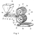
- Fig. 1 shows a three-dimensional representation of a device according to the invention for the production of a filter rod of the tobacco processing industry.
- Filter material is processed in a mixing and / or separating device 10 accordingly.
- the mixing and / or separating device 10 is described in more detail in the applicant's aforementioned European patent applications. It serves to separate filter material in the form of fibers and to mix with each other or to mix with granules such as activated carbon granules. It can be used a variety of ingredients such as Mehrfachkomponentenmaschinen, especially bicomponent fibers, which have already been mentioned above, other fibers, such as cellulose, cotton, hemp or the like., Charcoal or powdered or other additives.
- a preferred mixture of filter materials comprises 80 to 95% by weight of activated carbon granules and 5 to 20% by weight of bicomponent fibers from Trevira, which have already been mentioned above.
- the correspondingly separated and mixed filter material 19 is thrown onto a conveyor belt 11 to form a filter material layer 13 or a fleece or a fiber cake 13.
- a negative pressure 12 acts to compact the filter material a little or to transport the filter material safely on the conveyor belt 11 during the promotion.
- the filter material layer 13 is conveyed in the conveying direction 23 in the direction of a hollow drum pair in the form of two drum bags 14 and 14 '.
- the drum mills are arranged one above the other and rotate in the opposite direction in such a way that the filter material layer 13 reaching between the drum mills is initially conveyed for a short time in the same direction.
- the filter material layer 13 enters the effective region of the drum tubules 14 and 14 ', wherein by the edges 17 and edges 17 the filter drum a filter material strip 22 of the filter material layer 13 is separated and into a forming cavity from troughs 15 of the drum mills 14 and 14 'to be promoted.
- a circular Cross section In the moment in which the two opposite troughs 15 the respective bowl drums 14, 14 'lie exactly above one another, forms a closed cavity, a circular Cross section has. In this cavity, the filter rod is formed 16 off.
- the bowl drums 14 and 14 ' are at least in form-forming Heated area to at least the outer shell of the filter material, that has reached the hollows to melt. preferably, is the hollow drum 14 and the well drum 14 'permeable to air and hot air is passed through the bowl drums 14 and 14 ' and the filter material 19 drumming between the drum is located, directed. This heats the bicomponent fibers, so that the fibers stick together and with the granules can and form a composite.
- the conveyor belts 11 and 18 are deflected by pulleys 21.
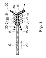
- the filter material layer 13 moves in the conveying direction 23 between two trough belts 20 and 20 ', the itself again troughs 15 and edges 17 have, which in itself the the bowl drums 14 and 14 'correspond.
- Conveyor belts can be the area where the filter material is full from the troughs 15 and the material of the trough belts 20 and 20 '. is wrapped, lengthened or enlarged, so that an influence Heating up can take more time.
- Fig. 2 only a section is shown, so that the endless Trough bands 20, 20 'are only partially shown.
- Fig. 2 also hot air with the reference numeral 25th shown.
- the trough belts 20 and 20 'permeable to air To pass hot air through the filter material to let it, it is expedient, the trough belts 20 and 20 'permeable to air.
- the drum mills 14 and 14 'shown in FIG. 1 are.
- Fig. 1 was hot air with the reference numeral 25 schematically shown.
Landscapes
- Engineering & Computer Science (AREA)
- Mechanical Engineering (AREA)
- Cigarettes, Filters, And Manufacturing Of Filters (AREA)
Abstract
Description
- Fördern wenigstens eines Filtermaterials in Form einer Schicht zu einer Filterstabformungsvorrichtung,
- Abnehmen eines länglichen Teils der Schicht, wobei die Längsachse des länglichen Teils quer zur Förderrichtung der Schicht ausgerichtet ist, und
- Formen des Filterstabs aus der Schicht bzw. dem länglichen Teil der Schicht.
- Fig. 1
- eine dreidimensionale schematische Darstellung einer erfindungsgemäßen Vorrichtung, und
- Fig. 2
- ein wesentlicher Teil einer erfindungsgemäßen Vorrichtung in einer anderen Ausführungsform in schematischer Darstellung.
Das entsprechend vereinzelte und gemischte Filtermaterial 19 wird auf ein Förderband 11 zu einer Filtermaterialschicht 13 bzw. einem Vlies oder einem Faserkuchen 13 aufgeschauert. Auf die Filtermaterialschicht 13 wirkt ein Unterdruck 12, um das Filtermaterial schon ein wenig zu kompaktieren bzw. das Filtermaterial sicher auf dem Förderband 11 bei der Förderung zu transportieren. Die Filtermaterialschicht 13 wird in Förderrichtung 23 in Richtung eines Muldentrommelpaars in Form zweier Muldentrommeln 14 und 14' gefördert. Die Muldentrommeln sind übereinander angeordnet und drehen sich gegensinnig dergestalt, dass die zwischen die Muldentrommeln gelangende Filtermaterialschicht 13 zunächst kurzzeitig in die gleiche Richtung weitergefördert wird.
- 10
- Misch- und/oder Vereinzelungsvorrichtung
- 11
- Förderband
- 12
- Unterdruck
- 13
- Filtermaterialschicht
- 14, 14'
- Muldentrommel
- 15
- Mulde
- 16
- Filterstab
- 17
- Rand
- 18
- Förderband
- 19
- Filtermaterial
- 20, 20'
- Muldenband
- 21
- Umlenkrolle
- 22
- Filtermaterialstreifen
- 23
- Förderrichtung
- 24
- Längsachse
- 25
- warmer Luftstrom
Claims (16)
- Verfahren zur Herstellung eines Filterstabs (16) der tabakverarbeitenden Industrie mit den folgenden Verfahrensschritten:Fördern wenigstens eines Filtermaterials (19) in Form einer Schicht (13) zu einer Filterstabformungsvorrichtung (14, 14', 20, 20'),Abnehmen eines länglichen Teils (22) der Schicht (13), wobei die Längsachse des länglichen Teils (22) quer zur Förderrichtung (23) der Schicht (13) ausgerichtet ist, undFormen des Filterstabs (16) aus der Schicht (13).
- Verfahren nach Anspruch 1, dadurch gekennzeichnet, dass die Schicht (13) ein Vlies ist, wobei wenigstens eine Sorte Fasern als Filtermaterial (19) vorgesehen ist.
- Verfahren nach Anspruch 2, dadurch gekennzeichnet, dass eine Sorte Fasern eine Mehrfachkomponentenfaser, insbesondere Bikomponentenfaser, ist.
- Verfahren nach einem oder mehreren der Ansprüche 1 bis 3, dadurch gekennzeichnet, dass ein Bestandteil des Filtermaterials (19) ein Additiv ist.
- Verfahren nach einem oder mehreren der Ansprüche 1 bis 4, dadurch gekennzeichnet, dass das Abnehmen des länglichen Teils (22) der Schicht (13) mittels Zusammenführen zweier Mulden (15) und wenigstens teilweise Bewegen der Mulden (15) in Förderrichtung (23) der Schicht (13) geschieht, wobei die Mulden (15), wenn sie zusammengeführt sind, einen Hohlraum bilden, der die Form des Filterstabs (16) aufweist.
- Verfahren nach einem oder mehreren der Ansprüche 1 bis 5, dadurch gekennzeichnet, dass der Filterstab (16) beim Formen erwärmt wird.
- Verfahren nach einem oder mehreren der Ansprüche 1 bis 6, dadurch gekennzeichnet, dass die Schicht (13) des Filtermaterials (19) durch Aufschauern des Filtermaterials (19) auf einen Förderer (11) erzeugt wird.
- Verfahren nach Anspruch 7, dadurch gekennzeichnet, dass das Filtermaterial (19) vor dem Aufschauern auf den Förderer (11) vereinzelt wird.
- Vorrichtung zur Herstellung eines Filterstabs (16) der tabakverarbeitenden Industrie mit einem Förderer (11) zum Fördern einer Schicht aus Filtermaterial (19) und einer Filterstabformungsvorrichtung (14, 14', 20, 20'), dadurch gekennzeichnet, dass die Filterstabformungsvorrichtung (14, 14', 20, 20') Mulden (15) umfasst, deren jeweilige Längsachse (24) quer zur Förderrichtung (23) des Förderers (11) ausgebildet ist.
- Vorrichtung nach Anspruch 9, dadurch gekennzeichnet, dass jeweils zwei Mulden (15) zusammenwirken, um einen Hohlraum zu bilden, der die Form eines Filterstabs (16) aufweist.
- Vorrichtung nach Anspruch 10, dadurch gekennzeichnet, dass die Mulden (15) halbkreisförmig sind.
- Vorrichtung nach einem oder mehreren der Ansprüche 9 bis 11, dadurch gekennzeichnet, dass die Ränder (17) der Mulden (15) scharf sind.
- Vorrichtung nach einem oder mehreren der Ansprüche 9 bis 12, dadurch gekennzeichnet, dass die Filterstabformungsvorrichtung (14, 14', 20, 20') wenigsten eine Muldenwalze (14, 14') und/oder wenigstens ein Muldenband (20, 20') umfasst.
- Vorrichtung nach einem oder mehreren der Ansprüche 9 bis 13, dadurch gekennzeichnet, dass die Filterstabformungsvorrichtung (14, 14', 20, 20') wenigstens teilweise erwärmbar ist.
- Vorrichtung nach einem oder mehreren der Ansprüche 9 bis 14, dadurch gekennzeichnet, dass der Förderer (11) ein Transportband ist.
- Vorrichtung nach einem oder mehreren der Ansprüche 9 bis 15, dadurch gekennzeichnet, dass eine Mischund/oder Vereinzelungsvorrichtung (10) vorgesehen ist, mittels der Filtermaterial (19) auf den Förderer (11) aufschauerbar ist.
Priority Applications (2)
| Application Number | Priority Date | Filing Date | Title |
|---|---|---|---|
| EP04016182A EP1504684B1 (de) | 2003-08-08 | 2004-07-09 | Verfahren und Vorrichtung zur Herstellung eines Filterstabs |
| PL04016182T PL1504684T3 (pl) | 2003-08-08 | 2004-07-09 | Sposób i urządzenie do wytwarzania pręcika filtru |
Applications Claiming Priority (3)
| Application Number | Priority Date | Filing Date | Title |
|---|---|---|---|
| EP03018111 | 2003-08-08 | ||
| EP03018111 | 2003-08-08 | ||
| EP04016182A EP1504684B1 (de) | 2003-08-08 | 2004-07-09 | Verfahren und Vorrichtung zur Herstellung eines Filterstabs |
Publications (2)
| Publication Number | Publication Date |
|---|---|
| EP1504684A1 true EP1504684A1 (de) | 2005-02-09 |
| EP1504684B1 EP1504684B1 (de) | 2006-05-24 |
Family
ID=33553821
Family Applications (1)
| Application Number | Title | Priority Date | Filing Date |
|---|---|---|---|
| EP04016182A Expired - Lifetime EP1504684B1 (de) | 2003-08-08 | 2004-07-09 | Verfahren und Vorrichtung zur Herstellung eines Filterstabs |
Country Status (2)
| Country | Link |
|---|---|
| EP (1) | EP1504684B1 (de) |
| PL (1) | PL1504684T3 (de) |
Cited By (1)
| Publication number | Priority date | Publication date | Assignee | Title |
|---|---|---|---|---|
| CN118068028A (zh) * | 2024-04-18 | 2024-05-24 | 昆明固佳自动化设备有限公司 | 一种基于机械臂、agv的成品烟叶在线质量检测装置 |
Citations (3)
| Publication number | Priority date | Publication date | Assignee | Title |
|---|---|---|---|---|
| GB740735A (en) * | 1953-10-14 | 1955-11-16 | Forgrove Mach | Improvements in apparatus for moulding tablets of plastic material |
| GB862884A (en) * | 1958-04-11 | 1961-03-15 | Personal Products Corp | Tampons |
| DE3130827A1 (de) * | 1980-08-04 | 1982-04-15 | Molins Ltd., London | Vorrichtung zur herstellung von fuellmaterial, hauptsaechlich fuer zigarettenfilter |
-
2004
- 2004-07-09 PL PL04016182T patent/PL1504684T3/pl unknown
- 2004-07-09 EP EP04016182A patent/EP1504684B1/de not_active Expired - Lifetime
Patent Citations (3)
| Publication number | Priority date | Publication date | Assignee | Title |
|---|---|---|---|---|
| GB740735A (en) * | 1953-10-14 | 1955-11-16 | Forgrove Mach | Improvements in apparatus for moulding tablets of plastic material |
| GB862884A (en) * | 1958-04-11 | 1961-03-15 | Personal Products Corp | Tampons |
| DE3130827A1 (de) * | 1980-08-04 | 1982-04-15 | Molins Ltd., London | Vorrichtung zur herstellung von fuellmaterial, hauptsaechlich fuer zigarettenfilter |
Cited By (1)
| Publication number | Priority date | Publication date | Assignee | Title |
|---|---|---|---|---|
| CN118068028A (zh) * | 2024-04-18 | 2024-05-24 | 昆明固佳自动化设备有限公司 | 一种基于机械臂、agv的成品烟叶在线质量检测装置 |
Also Published As
| Publication number | Publication date |
|---|---|
| EP1504684B1 (de) | 2006-05-24 |
| PL1504684T3 (pl) | 2006-09-29 |
Similar Documents
| Publication | Publication Date | Title |
|---|---|---|
| EP1464241B1 (de) | Verfahren zur Herstellung eines Vlieses für die Herstellung von Filtern der tabakverarbeitenden Industrie sowie Filterstrangherstelleinrichtung | |
| DE1657244B1 (de) | Verfahren und Vorrichtung zur Herstellung von Faserstaebchen,insbesondere zur Verwendung als Zigarettenfilter | |
| EP2289356A1 (de) | Vorrichtung zur Verarbeitung von Rauchartikelabfällen | |
| DE102010043474A1 (de) | Verfahren und Vorrichtung zum Einlegen von Objekten in einen Filterstrang der Tabak verarbeitenden Industrie | |
| EP1464239B1 (de) | Verfahren und Einrichtung zur Herstellung eines Filterstranges | |
| EP3298909A1 (de) | Herstellung von rauchartikelprodukten | |
| EP1464240B1 (de) | Verfahren und Vorrichtung zur Herstellung eines Vlieses für die Herstellung von Filterstäben | |
| EP2853165A1 (de) | Verfahren zum Herstellen von stabförmigen Artikeln der Tabak verarbeitenden Industrie und Saugfördervorrichtung | |
| CH628783A5 (de) | Maschine zur herstellung von zigarettenfilterstaeben. | |
| EP1464238A1 (de) | Verfahren zur Aufbereitung endlicher Fasern und Aufbereitungseinrichtung für endliche Fasern zur Verwedung bei der Herstellung von Filtern | |
| EP3641572A1 (de) | Verfahren zum herstellen von rauchartikelprodukten | |
| DE102016212095A1 (de) | Vorrichtung und Verfahren zur Ausrichtung von Ausschusszigaretten und Einrichtung zur Separation von Ausschussmaterial der Zigarettenherstellung | |
| EP1504684B1 (de) | Verfahren und Vorrichtung zur Herstellung eines Filterstabs | |
| DE19854662B4 (de) | Tabakschneidverfahren und -vorrichtung | |
| DE69027259T2 (de) | Kontrollierte Öffnung eines faserigen Materials | |
| EP2532257B1 (de) | Fördertrommel der Tabak verarbeitenden Industrie | |
| EP1405573B1 (de) | Egalisator für eine Zigarettenstrangmaschine | |
| EP1504682B1 (de) | Verfahren und Vorrichtung zur Herstellung eines Filterstabs | |
| EP1532881A2 (de) | Verfahren und Vorrichtung zur Herstellung eines umhüllungsmaterialstreifenfreien Filterstrangs der tabakverarbeitenden Industrie | |
| WO2024227683A1 (de) | Maschine der tabak verarbeitenden industrie, zufuhrvorrichtung und verwendung derselben zum zuführen eines heizstreifens, verfahren zum herstellen eines strangs sowie stabförmiger artikel der tabak verarbeitenden industrie | |
| DE102006018102A1 (de) | Faserfilterherstellung | |
| EP1504681B2 (de) | Verfahren und Vorrichtung zur Herstellung eines Filterstrangs | |
| DE102015010563A1 (de) | Maschine zum Herstellen eines stabförmigen Artikels aus pflanzlicher Folie im Strangverfahren | |
| JP2005058232A (ja) | フィルタロッドを製造する方法と装置 | |
| EP3266319A1 (de) | Verfahren und einrichtung zur separation von ausschussmaterial der zigarettenherstellung |
Legal Events
| Date | Code | Title | Description |
|---|---|---|---|
| PUAI | Public reference made under article 153(3) epc to a published international application that has entered the european phase |
Free format text: ORIGINAL CODE: 0009012 |
|
| AK | Designated contracting states |
Kind code of ref document: A1 Designated state(s): AT BE BG CH CY CZ DE DK EE ES FI FR GB GR HU IE IT LI LU MC NL PL PT RO SE SI SK TR |
|
| AX | Request for extension of the european patent |
Extension state: AL HR LT LV MK |
|
| 17P | Request for examination filed |
Effective date: 20050708 |
|
| GRAP | Despatch of communication of intention to grant a patent |
Free format text: ORIGINAL CODE: EPIDOSNIGR1 |
|
| AKX | Designation fees paid |
Designated state(s): AT BE BG CH CY CZ DE DK EE ES FI FR GB GR HU IE IT LI LU MC NL PL PT RO SE SI SK TR |
|
| GRAS | Grant fee paid |
Free format text: ORIGINAL CODE: EPIDOSNIGR3 |
|
| GRAA | (expected) grant |
Free format text: ORIGINAL CODE: 0009210 |
|
| AK | Designated contracting states |
Kind code of ref document: B1 Designated state(s): AT BE BG CH CY CZ DE DK EE ES FI FR GB GR HU IE IT LI LU MC NL PL PT RO SE SI SK TR |
|
| PG25 | Lapsed in a contracting state [announced via postgrant information from national office to epo] |
Ref country code: SI Free format text: LAPSE BECAUSE OF FAILURE TO SUBMIT A TRANSLATION OF THE DESCRIPTION OR TO PAY THE FEE WITHIN THE PRESCRIBED TIME-LIMIT Effective date: 20060524 Ref country code: FI Free format text: LAPSE BECAUSE OF FAILURE TO SUBMIT A TRANSLATION OF THE DESCRIPTION OR TO PAY THE FEE WITHIN THE PRESCRIBED TIME-LIMIT Effective date: 20060524 Ref country code: IE Free format text: LAPSE BECAUSE OF FAILURE TO SUBMIT A TRANSLATION OF THE DESCRIPTION OR TO PAY THE FEE WITHIN THE PRESCRIBED TIME-LIMIT Effective date: 20060524 Ref country code: CZ Free format text: LAPSE BECAUSE OF FAILURE TO SUBMIT A TRANSLATION OF THE DESCRIPTION OR TO PAY THE FEE WITHIN THE PRESCRIBED TIME-LIMIT Effective date: 20060524 Ref country code: SK Free format text: LAPSE BECAUSE OF FAILURE TO SUBMIT A TRANSLATION OF THE DESCRIPTION OR TO PAY THE FEE WITHIN THE PRESCRIBED TIME-LIMIT Effective date: 20060524 Ref country code: GB Free format text: LAPSE BECAUSE OF FAILURE TO SUBMIT A TRANSLATION OF THE DESCRIPTION OR TO PAY THE FEE WITHIN THE PRESCRIBED TIME-LIMIT Effective date: 20060524 Ref country code: RO Free format text: LAPSE BECAUSE OF FAILURE TO SUBMIT A TRANSLATION OF THE DESCRIPTION OR TO PAY THE FEE WITHIN THE PRESCRIBED TIME-LIMIT Effective date: 20060524 |
|
| REG | Reference to a national code |
Ref country code: GB Ref legal event code: FG4D Free format text: NOT ENGLISH |
|
| REG | Reference to a national code |
Ref country code: CH Ref legal event code: EP |
|
| REG | Reference to a national code |
Ref country code: IE Ref legal event code: FG4D Free format text: LANGUAGE OF EP DOCUMENT: GERMAN |
|
| REF | Corresponds to: |
Ref document number: 502004000612 Country of ref document: DE Date of ref document: 20060629 Kind code of ref document: P |
|
| PG25 | Lapsed in a contracting state [announced via postgrant information from national office to epo] |
Ref country code: MC Free format text: LAPSE BECAUSE OF NON-PAYMENT OF DUE FEES Effective date: 20060731 Ref country code: BE Free format text: LAPSE BECAUSE OF NON-PAYMENT OF DUE FEES Effective date: 20060731 |
|
| PG25 | Lapsed in a contracting state [announced via postgrant information from national office to epo] |
Ref country code: SE Free format text: LAPSE BECAUSE OF FAILURE TO SUBMIT A TRANSLATION OF THE DESCRIPTION OR TO PAY THE FEE WITHIN THE PRESCRIBED TIME-LIMIT Effective date: 20060824 Ref country code: DK Free format text: LAPSE BECAUSE OF FAILURE TO SUBMIT A TRANSLATION OF THE DESCRIPTION OR TO PAY THE FEE WITHIN THE PRESCRIBED TIME-LIMIT Effective date: 20060824 |
|
| PG25 | Lapsed in a contracting state [announced via postgrant information from national office to epo] |
Ref country code: ES Free format text: LAPSE BECAUSE OF FAILURE TO SUBMIT A TRANSLATION OF THE DESCRIPTION OR TO PAY THE FEE WITHIN THE PRESCRIBED TIME-LIMIT Effective date: 20060904 |
|
| PG25 | Lapsed in a contracting state [announced via postgrant information from national office to epo] |
Ref country code: PT Free format text: LAPSE BECAUSE OF FAILURE TO SUBMIT A TRANSLATION OF THE DESCRIPTION OR TO PAY THE FEE WITHIN THE PRESCRIBED TIME-LIMIT Effective date: 20061024 |
|
| GBV | Gb: ep patent (uk) treated as always having been void in accordance with gb section 77(7)/1977 [no translation filed] |
Effective date: 20060524 |
|
| REG | Reference to a national code |
Ref country code: IE Ref legal event code: FD4D |
|
| PLBE | No opposition filed within time limit |
Free format text: ORIGINAL CODE: 0009261 |
|
| STAA | Information on the status of an ep patent application or granted ep patent |
Free format text: STATUS: NO OPPOSITION FILED WITHIN TIME LIMIT |
|
| 26N | No opposition filed |
Effective date: 20070227 |
|
| EN | Fr: translation not filed | ||
| PGFP | Annual fee paid to national office [announced via postgrant information from national office to epo] |
Ref country code: PL Payment date: 20070619 Year of fee payment: 4 |
|
| PGFP | Annual fee paid to national office [announced via postgrant information from national office to epo] |
Ref country code: DE Payment date: 20070820 Year of fee payment: 4 |
|
| PG25 | Lapsed in a contracting state [announced via postgrant information from national office to epo] |
Ref country code: AT Free format text: LAPSE BECAUSE OF NON-PAYMENT OF DUE FEES Effective date: 20060709 |
|
| BERE | Be: lapsed |
Owner name: HAUNI MASCHINENBAU A.G. Effective date: 20060731 |
|
| PG25 | Lapsed in a contracting state [announced via postgrant information from national office to epo] |
Ref country code: GR Free format text: LAPSE BECAUSE OF FAILURE TO SUBMIT A TRANSLATION OF THE DESCRIPTION OR TO PAY THE FEE WITHIN THE PRESCRIBED TIME-LIMIT Effective date: 20060825 Ref country code: FR Free format text: LAPSE BECAUSE OF FAILURE TO SUBMIT A TRANSLATION OF THE DESCRIPTION OR TO PAY THE FEE WITHIN THE PRESCRIBED TIME-LIMIT Effective date: 20070309 |
|
| PG25 | Lapsed in a contracting state [announced via postgrant information from national office to epo] |
Ref country code: EE Free format text: LAPSE BECAUSE OF FAILURE TO SUBMIT A TRANSLATION OF THE DESCRIPTION OR TO PAY THE FEE WITHIN THE PRESCRIBED TIME-LIMIT Effective date: 20060524 Ref country code: BG Free format text: LAPSE BECAUSE OF FAILURE TO SUBMIT A TRANSLATION OF THE DESCRIPTION OR TO PAY THE FEE WITHIN THE PRESCRIBED TIME-LIMIT Effective date: 20060824 |
|
| PG25 | Lapsed in a contracting state [announced via postgrant information from national office to epo] |
Ref country code: TR Free format text: LAPSE BECAUSE OF FAILURE TO SUBMIT A TRANSLATION OF THE DESCRIPTION OR TO PAY THE FEE WITHIN THE PRESCRIBED TIME-LIMIT Effective date: 20060524 Ref country code: HU Free format text: LAPSE BECAUSE OF FAILURE TO SUBMIT A TRANSLATION OF THE DESCRIPTION OR TO PAY THE FEE WITHIN THE PRESCRIBED TIME-LIMIT Effective date: 20061125 Ref country code: LU Free format text: LAPSE BECAUSE OF NON-PAYMENT OF DUE FEES Effective date: 20060709 |
|
| PG25 | Lapsed in a contracting state [announced via postgrant information from national office to epo] |
Ref country code: CY Free format text: LAPSE BECAUSE OF FAILURE TO SUBMIT A TRANSLATION OF THE DESCRIPTION OR TO PAY THE FEE WITHIN THE PRESCRIBED TIME-LIMIT Effective date: 20060524 Ref country code: FR Free format text: LAPSE BECAUSE OF FAILURE TO SUBMIT A TRANSLATION OF THE DESCRIPTION OR TO PAY THE FEE WITHIN THE PRESCRIBED TIME-LIMIT Effective date: 20060524 |
|
| REG | Reference to a national code |
Ref country code: CH Ref legal event code: PL |
|
| NLV4 | Nl: lapsed or anulled due to non-payment of the annual fee |
Effective date: 20090201 |
|
| PG25 | Lapsed in a contracting state [announced via postgrant information from national office to epo] |
Ref country code: DE Free format text: LAPSE BECAUSE OF NON-PAYMENT OF DUE FEES Effective date: 20090203 |
|
| PG25 | Lapsed in a contracting state [announced via postgrant information from national office to epo] |
Ref country code: NL Free format text: LAPSE BECAUSE OF NON-PAYMENT OF DUE FEES Effective date: 20090201 |
|
| PG25 | Lapsed in a contracting state [announced via postgrant information from national office to epo] |
Ref country code: CH Free format text: LAPSE BECAUSE OF NON-PAYMENT OF DUE FEES Effective date: 20080731 Ref country code: LI Free format text: LAPSE BECAUSE OF NON-PAYMENT OF DUE FEES Effective date: 20080731 |
|
| PG25 | Lapsed in a contracting state [announced via postgrant information from national office to epo] |
Ref country code: IT Free format text: LAPSE BECAUSE OF NON-PAYMENT OF DUE FEES Effective date: 20080709 |
|
| PGFP | Annual fee paid to national office [announced via postgrant information from national office to epo] |
Ref country code: IT Payment date: 20070731 Year of fee payment: 4 |
|
| REG | Reference to a national code |
Ref country code: PL Ref legal event code: LAPE |
|
| PG25 | Lapsed in a contracting state [announced via postgrant information from national office to epo] |
Ref country code: PL Free format text: LAPSE BECAUSE OF NON-PAYMENT OF DUE FEES Effective date: 20080709 |