EP1504550B1 - End user control of a teleconferencing network through a data network - Google Patents
End user control of a teleconferencing network through a data network Download PDFInfo
- Publication number
- EP1504550B1 EP1504550B1 EP03736618.4A EP03736618A EP1504550B1 EP 1504550 B1 EP1504550 B1 EP 1504550B1 EP 03736618 A EP03736618 A EP 03736618A EP 1504550 B1 EP1504550 B1 EP 1504550B1
- Authority
- EP
- European Patent Office
- Prior art keywords
- data network
- teleconferencing
- teleconference
- computerized method
- data
- Prior art date
- Legal status (The legal status is an assumption and is not a legal conclusion. Google has not performed a legal analysis and makes no representation as to the accuracy of the status listed.)
- Expired - Lifetime
Links
- 238000000034 method Methods 0.000 claims description 98
- 230000009471 action Effects 0.000 claims description 40
- 230000008569 process Effects 0.000 claims description 14
- 230000008859 change Effects 0.000 claims description 7
- 230000000977 initiatory effect Effects 0.000 claims description 6
- 230000004044 response Effects 0.000 claims description 3
- 238000004590 computer program Methods 0.000 claims description 2
- 238000012544 monitoring process Methods 0.000 claims description 2
- 238000012545 processing Methods 0.000 description 7
- 238000004891 communication Methods 0.000 description 5
- 230000006870 function Effects 0.000 description 5
- 238000010586 diagram Methods 0.000 description 4
- 238000007726 management method Methods 0.000 description 4
- 230000008878 coupling Effects 0.000 description 3
- 238000010168 coupling process Methods 0.000 description 3
- 238000005859 coupling reaction Methods 0.000 description 3
- 230000005540 biological transmission Effects 0.000 description 2
- 230000007423 decrease Effects 0.000 description 1
- 230000001419 dependent effect Effects 0.000 description 1
- 238000005516 engineering process Methods 0.000 description 1
- 230000014509 gene expression Effects 0.000 description 1
- 239000004973 liquid crystal related substance Substances 0.000 description 1
- 239000000463 material Substances 0.000 description 1
- 230000003287 optical effect Effects 0.000 description 1
- 230000002093 peripheral effect Effects 0.000 description 1
- 230000003068 static effect Effects 0.000 description 1
- 238000012546 transfer Methods 0.000 description 1
- 238000013519 translation Methods 0.000 description 1
- 238000010200 validation analysis Methods 0.000 description 1
- 230000000007 visual effect Effects 0.000 description 1
Images


Classifications
-
- H—ELECTRICITY
- H04—ELECTRIC COMMUNICATION TECHNIQUE
- H04M—TELEPHONIC COMMUNICATION
- H04M7/00—Arrangements for interconnection between switching centres
- H04M7/0024—Services and arrangements where telephone services are combined with data services
- H04M7/0027—Collaboration services where a computer is used for data transfer and the telephone is used for telephonic communication
-
- H—ELECTRICITY
- H04—ELECTRIC COMMUNICATION TECHNIQUE
- H04M—TELEPHONIC COMMUNICATION
- H04M3/00—Automatic or semi-automatic exchanges
- H04M3/42—Systems providing special services or facilities to subscribers
- H04M3/56—Arrangements for connecting several subscribers to a common circuit, i.e. affording conference facilities
- H04M3/563—User guidance or feature selection
-
- H—ELECTRICITY
- H04—ELECTRIC COMMUNICATION TECHNIQUE
- H04M—TELEPHONIC COMMUNICATION
- H04M3/00—Automatic or semi-automatic exchanges
- H04M3/42—Systems providing special services or facilities to subscribers
- H04M3/56—Arrangements for connecting several subscribers to a common circuit, i.e. affording conference facilities
- H04M3/567—Multimedia conference systems
-
- H—ELECTRICITY
- H04—ELECTRIC COMMUNICATION TECHNIQUE
- H04M—TELEPHONIC COMMUNICATION
- H04M2201/00—Electronic components, circuits, software, systems or apparatus used in telephone systems
- H04M2201/38—Displays
-
- H—ELECTRICITY
- H04—ELECTRIC COMMUNICATION TECHNIQUE
- H04M—TELEPHONIC COMMUNICATION
- H04M2203/00—Aspects of automatic or semi-automatic exchanges
- H04M2203/50—Aspects of automatic or semi-automatic exchanges related to audio conference
- H04M2203/5081—Inform conference party of participants, e.g. of change of participants
-
- H—ELECTRICITY
- H04—ELECTRIC COMMUNICATION TECHNIQUE
- H04M—TELEPHONIC COMMUNICATION
- H04M3/00—Automatic or semi-automatic exchanges
- H04M3/38—Graded-service arrangements, i.e. some subscribers prevented from establishing certain connections
-
- H—ELECTRICITY
- H04—ELECTRIC COMMUNICATION TECHNIQUE
- H04M—TELEPHONIC COMMUNICATION
- H04M3/00—Automatic or semi-automatic exchanges
- H04M3/42—Systems providing special services or facilities to subscribers
- H04M3/42025—Calling or Called party identification service
- H04M3/42034—Calling party identification service
- H04M3/42042—Notifying the called party of information on the calling party
-
- H—ELECTRICITY
- H04—ELECTRIC COMMUNICATION TECHNIQUE
- H04M—TELEPHONIC COMMUNICATION
- H04M3/00—Automatic or semi-automatic exchanges
- H04M3/42—Systems providing special services or facilities to subscribers
- H04M3/42136—Administration or customisation of services
- H04M3/42153—Administration or customisation of services by subscriber
- H04M3/42161—Administration or customisation of services by subscriber via computer interface
-
- H—ELECTRICITY
- H04—ELECTRIC COMMUNICATION TECHNIQUE
- H04M—TELEPHONIC COMMUNICATION
- H04M3/00—Automatic or semi-automatic exchanges
- H04M3/42—Systems providing special services or facilities to subscribers
- H04M3/56—Arrangements for connecting several subscribers to a common circuit, i.e. affording conference facilities
- H04M3/568—Arrangements for connecting several subscribers to a common circuit, i.e. affording conference facilities audio processing specific to telephonic conferencing, e.g. spatial distribution, mixing of participants
- H04M3/569—Arrangements for connecting several subscribers to a common circuit, i.e. affording conference facilities audio processing specific to telephonic conferencing, e.g. spatial distribution, mixing of participants using the instant speaker's algorithm
Definitions
- This invention relates generally to teleconferencing networks, and more particularly to end user control of a teleconferencing network through a data network.
- a participant in a voice teleconferencing session generally may control his/her participation in the session by pressing key combinations on the telephone key pad, which sends DTMF signals to a conference controller.
- a menu of available options for the teleconference may be presented on a workstation connected to a data network.
- a data network server sends signals equivalent to the corresponding DTMF signals to the conference controller.
- an end user is able to affect only his/her own participation in the conference and is unable to assert control over other participants.
- US 4796293 discloses a conferencing system in which a conference coordinator has access to various commands for controlling a conference, including adding a conferee, splitting off a sub-conference, and changing a conferee between "talk" and "listen-only” modes.
- US 6148068 discloses a conferencing system that includes a voice processing server and a web server. Conference participants can participate in a web portion of the conference as well as an audio portion. A conference control panel is provided allowing users to input commands that are relayed to the web server. The control panel can be viewed by each participant.
- a user connected to a data network controls a parallel teleconference network by sending requests through the data network.
- the requests are validated against permissions granted to the user and an action associated with a request is performed at the teleconferencing network if the request is validated.
- a status for a teleconference hosted by the teleconferencing network may be sent when the action is performed or when other changes occur during the teleconference.
- a voice and/or data message also may be sent to the user(s) that are affected by the action.
- the allowed actions are presented to the user through the data network.
- a graphical user interface for controlling the teleconferencing network is presented to the user through the data network.
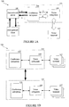
- FIG. 1A illustrates a teleconferencing system 100 consisting of a teleconferencing network server 101 and a data network server 109.
- the teleconferencing network server 101 controls a voice network for a teleconference session and a parallel data-based conference, such as may be conducted over the World Wide Web.
- the data network server 109 and the teleconferencing network server 101 may be connected through directly or through a standard computer network topology, such as a local or wide-area network, operating in accordance any communication protocol, and through any communications medium.
- the data network server 109 is coupled to one or more client systems, illustrated generally as data network client 111, using any standard computer network, protocol and medium.
- a teleconference participant receives and sends information for the parallel data conference through the client 111 using, for example, a graphical user interface.
- the graphical user interface may implemented as web pages sent from the data server 109 for presentation to the user through a web browser executing on the client 111.
- the teleconferencing network server 101 comprises a conference subsystem 103 and a voice subsystem 105.
- the voice subsystem 105 controls the operation of the voice network, illustrated generally as voice terminal 107, during a teleconferencing session.
- the voice subsystem 105 may be a telephone switch for a PBX (private branch exchange) or PSTN (public switched telephone network) voice network.
- the voice terminal 107 may be a standard telephone set or one with voice-over-IP capability that is connected into the voice subsystem 105 through the Internet.
- the conference subsystem 103 receives the user input from the data network server 109 and sends the appropriate control signals to the voice subsystem 105.
- the conference subsystem 103 is also responsible for setting up and monitoring a teleconference session through the voice subsystem 103.
- the control actions available to all users include temporarily muting, and subsequently un-muting, oneself.
- the user may move to a voice breakout room, and optionally a data breakout room.
- Actions affecting other teleconference participants are restricted to certain users, such as muting the person who is currently talking in the teleconference, muting other people in the teleconference, permanently changing the speaking ability of someone in the teleconference, or renaming a participant.
- Additional restricted actions include ejecting someone from the teleconference session and the parallel data session, locking the teleconference session, and optionally the parallel data session, from entry by new users, and setting up the teleconference, such as by calling individual people or by instructing the conference subsystem 104 call a set of people.
- the data network client 111 receives user input and forwards the input in a message to the data network server 109 as illustrated by arrow 1. If the input is a control action that is restricted, the data network server 109 verifies that the particular user has the appropriate level of permission for the action. In one embodiment, the user's permission levels are stored in a user profile created when the user registers for a teleconference session. Assuming the user is permitted to request the action, the data network server 109 sends a request message to the conference subsystem 103 as illustrated by arrow 2. In an alternate embodiment, the user profiles are stored on the conference subsystem 103 and server 109 sends the input to the conference subsystem 103 for validation.
- the conference subsystem 103 evaluates the request message and sends the corresponding control signal to the voice subsystem 105 as illustrated by arrow 3.
- the conference subsystem 103 may also send a message to the voice terminal 107 through the voice subsystem 105 as illustrated by arrows 4 and 5.
- the conference subsystem 103 also receives control information from the voice subsystem 105 through the connection illustrated as arrow 3, which enables the conference subsystem 103 to update the status of the teleconference session at the data network client 111 interface.
- the conference subsystem 103 informs the data network server 109 of the current speaker(s) so that information can be presented to the user.
- Teleconferencing network server 101 controls the voice terminals 107 in one region while teleconferencing network server 121 controls the voice terminals 127 in a different region.
- the teleconference network server in the conference scheduler's region would initiate a call to the other teleconference network server(s) to set up the teleconference.
- Each participant is connected to the teleconferencing network server nearest them.
- the teleconferencing network server 101 is located in New York and the server 121 is located in London, the participants in the United States and those in the United Kingdom can hold a joint teleconference that requires only a single transatlantic connection between the servers 101, 121.
- the data network is a wide-area network, such as the Internet
- a single data network server can control the data network clients in both countries, sending and receiving messages to/from the teleconference network servers 101, 121 as appropriate.
- the methods to be performed by a computer constitute computer programs made up of computer-executable instructions illustrated as blocks (acts). Describing the methods by reference to a flowchart enables one skilled in the art to develop such programs including such instructions to carry out the methods on suitably configured computers (the processing unit of the computer executing the instructions from computer-readable media) acting as clients or servers in accordance with the invention.
- the computer-executable instructions may be written in a computer programming language or may be embodied in firmware logic. If written in a programming language conforming to a recognized standard, such instructions can be executed on a variety of hardware platforms and for interface to a variety of operating systems.
- the method performed by the data network client 111 is illustrated in Figure 2A and the method performed by the data network server 109 is illustrated in Figure 2B .
- Two flowcharts in Figures 2C-D illustrated the methods performed by the teleconference network server 101 and include the functions described above for the conference subsystem 103 and for the voice subsystem 105.
- the methods executed by the data network client and data network server are described in terms of a web-based data conference but are equally applicable to other types of data sessions that parallel teleconference sessions. Furthermore, the methods are described as exchanging data in messages but no particular message protocol is implied or required.
- a data client method 200 is executed by a data client upon receipt of input from the user or a message from the data server (block 201).
- User input is formatted into a message and sent to the data server (block 203) where it is processed as described below in conjunction with Figure 2B .
- the user When the user requests an action be performed on another participant, the user selects the participant, which sends an identifier for the participant to the data server at block 203.
- the data server may return an error message if the user does not have permission to perform any action on another person (block 205), or a list specifying the actions permitted to the user (block 209).
- the method 200 outputs any error message to the user at block 207.
- the permitted actions are output as web page menu or tool bar at block 211 and the user is prompted to for a selection.
- the user is assigned a permission level based on the type of the user. For example, a user who is not profiled (“guest”) is only allowed to mute/unmute himself/herself, while a profiled user is allowed to temporarily mute others as well.
- the ability to mute the participant who is currently speaking enables a user to avoid having to listen to extraneous conversations, "music-on-hold," and noise on the line of the other person.
- allowing a user to control other participants relieves the presenter of the responsibility of moderating the teleconference during the presentation.
- the scheduler of the teleconference is allowed permanently change the speaking ability of participants and to eject a participant from the voice and data sessions when necessary.
- Additional error messages result from the user attempting to enter a locked voice or data conference.
- the method 200 may also subsequently prompt the user at block 211 for other information, such as a telephone number required to call an invitee not currently participating in the teleconference session.
- Messages regarding the status of the teleconference update the portions of the client's web page, such as tool bars, menus, and participant list (block 213).
- Various visual indicators may be used to indicate the current characteristics and status of each participant, such as name, speaking ability (e.g., temporarily or permanently muted), participation (e.g., voice-only conference, data-only conference, voice/data breakout room, ejected), current speaker, etc.
- all invitees to the teleconference are listed and marked as participating or not.
- a data server method 220 shown in Figure 2B executes on a server controlling a data network providing a parallel data conference session, such as the data network server 109 in Figure 1A .
- the method 220 receives messages from the data client method 200 and from methods executing on the teleconference network server 101 that are described in conjunction in Figures 2C-D below.
- the data server method 220 determines if the message is from a data client (block 221). If so, the method 220 determines if the request is permitted (block 223). For example, if the user is attempting to join a locked conference, the request will be denied.
- the processing at block 223 includes checking the user's permissions if the request affects another person, such as when the message contains a participant identifier or a call request to an individual, team, or missing conference invitees.
- the method 220 sends an error message to the data client method at block 225 if the request is not permitted.
- Permitted actions are processed at block 227 to determine if more data is needed, such as, for example, a call request that requires a phone number. Assuming no additional data is needed, a message is sent to the conference server containing the requested action and any required data at block 231, where it is processed as described further below. Additional data is requested through a web page created by the data server method 220 and sent to the data client for presentation to the user at block 229. If the message from the client method 200 specifies a participant identifier, the method 220 formats a web page at block 229 that contains the actions permitted to the user according to the profile and sends the selected action and participant identifier returned by the data client to the teleconference network server at block 231.
- the data server method 220 also locks and unlocks a parallel data conference session as illustrated at blocks 233 until 239.
- the voice conference may be locked/unlocked in conjunction with locking/unlocking the data conference as described below with reference to Figure 2C .
- a web page showing the updated status of the data conference session is sent to all data clients participating in the particular data conference session at block 249.
- the data server method 220 determines if the message is a "now speaking" message containing a list of speakers in the voice conference (block 241). If not, the message is a result message that provides a status of the user's last request and a web page containing the updated status is sent to the data client at block 243. If the user's original request was to move to a voice breakout room and a data breakout room (block 245), the data server method 220 moves the client to the requested data breakout room and informs the affected data client of the change at block 247. The data clients for the other conference participants are sent updated web pages at block 249.
- the functions performed by the conference subsystem and the voice subsystem are illustrated as a single conference method 250 in Figure 2C , which utilizes a supporting voice conference call method 253 in Figure 2D .
- the conference server method 250 consists of two parallel threads of processing. In one thread, illustrated as blocks 251 until 271, the method 250 processes messages from the data server method 220. The other thread, illustrated as block 273 until 291, monitors a voice conference to determine which participants are speaking.
- the method 250 Upon receipt of a message from the data server method 220, the method 250 determines the type of request at blocks 251, 255 and 259. Call requests are processed by the supporting call method 253 (block 253). Locking or unlocking a voice conference is accomplished at blocks 257 and 261, respectively, and maybe performed in concert with the locking of the parallel data conference as previously described in conjunction with Figure 2B . The method 250 evaluates other requests are evaluated at block 263 to determine if the action requested is allowed, i.e. the user may be attempting to join a locked voice conference. An error message is sent to the data server at block 265 if the action is not allowed for subsequent delivery to the user as previously described in Figures 2A and 2B .
- Allowed actions are performed at block 267, and a result message is sent to the data server method 220 at block 271.
- An optional voice message may sent to the voice terminal (block 269, shown in phantom) to audibly inform the user of the change, i.e., muted, unmuted, etc. It will be appreciated that the actions at block 267 that affect the operations of the voice terminals are performed by the components of the teleconferencing network server that controls the voice conference.
- the call method 253 may be incorporated into a prior art process that sets up teleconferences or may be implemented as a separate procedure.
- the embodiment of the call method 253 illustrated in Figure 2D enables one teleconferencing network server to communicate with other teleconferencing network servers to set up a teleconference, as well as providing support for various call commands requested by the user.
- the call method 253 determines if the user is initiating a multiserver meeting (block 293) and, if so, sets up a multiserver meeting as described below in conjunction with block 315. Otherwise, the method 253 dials the primary number for the specified participant(s) at block 295. If the call is a manual call in which the user wants to talk the other person (block 301), the conference server connects the user to the line (block 303). Subsequently, the called person may elect to join the conference at block 311.
- the conference server determines if there is an answer for each of the people called (block 305) and may optionally dial an alternate number if there is no answer (block 307, shown in phantom). If there is an answer, the method 253 plays a voice message for the person that instructs them to press certain buttons on the voice terminal to join or decline to join the conference. If the user elects to join the conference at block 311, the corresponding voice line is connected into the conference (block 313). In an alternate embodiment, the caller may also talk to the people called, if desired, before the voice message is played.
- a call request for a multiserver meeting includes one or more teleconferencing network server identifiers associated with invitees that connect to servers other than the initiating teleconferencing network server, i.e., the server for the user initiating the meeting.
- the method 253 connects the identified teleconferencing network servers to the initiating teleconferencing network server. It will be appreciated that the processing represented by block 315 includes the operations necessary to couple the teleconferencing network servers through a voice connection and one of skill in the art will understand the required operations without additional explanation. It will also be appreciated that Figure 2D implies no particular order in which the servers and the participants are connected into the multiserver teleconference.
- the method 250 measures the voice levels of the participants in the voice conference (block 275) and creates an initial list of current speakers (as opposed to those who have the ability to speak), i.e. participants whose voice levels exceed a threshold value (block 277).
- the list of speakers is sent to the data server method 220 at block 277. In one embodiment, the list may show multiple current speakers, with the number of speakers determined by system options or defaults.
- the conference server continues to measure the voice levels during the conference to update the list of speakers (block 279).
- the method 250 adds the participant's identifier to the list at block 291 and sends the new list to the data server method 220 at block 287, which updates the data clients for the users that are participating in the voice conference as previously described. If a voice signal for a participant that is currently on the list falls below the threshold (block 283), the participant's identifier is removed from the list at block 285 and the new list is sent at block 287.
- Figures 3A-B are intended to provide an overview of computer hardware and other operating components suitable for performing the methods of the invention described above, but is not intended to limit the applicable environments.
- One of skill in the art will immediately appreciate that the invention can be practiced with other computer system configurations, including hand-held devices, multiprocessor systems, microprocessor-based or programmable consumer electronics, network PCs, minicomputers, mainframe computers, and the like.
- the invention can also be practiced in distributed computing environments where tasks are performed by remote processing devices that are linked through a communications network.
- FIG. 3A shows several computer systems that are coupled together through a network 3, such as the Internet.
- the term "Internet” as used herein refers to a network of networks which uses certain protocols, such as the TCP/IP protocol, and possibly other protocols such as the hypertext transfer protocol (HTTP) for hypertext markup language (HTML) documents that make up the World Wide Web (web).
- HTTP hypertext transfer protocol
- HTML hypertext markup language
- the physical connections of the Internet and the protocols and communication procedures of the Internet are well known to those of skill in the art.
- Access to the Internet 3 is typically provided by Internet service providers (ISP), such as the ISPs 5 and 7.
- ISP Internet service providers
- client systems such as client computer systems 21, 25, 35, and 37 obtain access to the Internet through the Internet service providers, such as ISPs 5 and 7.
- Access to the Internet allows users of the client computer systems to exchange information, receive and send e-mails, and view documents, such as documents which have been prepared in the HTML format.
- documents are often provided by web servers, such as web server 9 which is considered to be "on" the Internet.
- web servers such as web server 9 which is considered to be "on” the Internet.
- these web servers are provided by the ISPs, such as ISP 5, although a computer system can be set up and connected to the Internet without that system being also an ISP as is well known in the art.
- the web server 9 is typically at least one computer system which operates as a server computer system and is configured to operate with the protocols of the World Wide Web and is coupled to the Internet.
- the web server 9 can be part of an ISP which provides access to the Internet for client systems.
- the web server 9 is shown coupled to the server computer system 11 which itself is coupled to web content 10, which can be considered a form of a media database. It will be appreciated that while two computer systems 9 and 11 are shown in Figure 3A , the web server system 9 and the server computer system 11 can be one computer system having different software components providing the web server functionality and the server functionality provided by the server computer system 11 which will be described further below.
- Client computer systems 21, 25, 35, and 37 can each, with the appropriate web browsing software, view HTML pages provided by the web server 9.
- the ISP 5 provides Internet connectivity to the client computer system 21 through the modem interface 23 which can be considered part of the client computer system 21.
- the client computer system can be a personal computer system, a network computer, a Web TV system, or other such computer system.
- the ISP 7 provides Internet connectivity for client systems 25, 35, and 37, although as shown in Figure 3A , the connections are not the same for these three computer systems.
- Client computer system 25 is coupled through a modem interface 27 while client computer systems 35 and 37 are part of a LAN.
- FIG. 3A shows the interfaces 23 and 27 as generically as a "modem,” it will be appreciated that each of these interfaces can be an analog modem, ISDN modem, cable modem, satellite transmission interface (e.g. "Direct PC"), or other interfaces for coupling a computer system to other computer systems.
- Client computer systems 35 and 37 are coupled to a LAN 33 through network interfaces 39 and 41, which can be Ethernet network or other network interfaces.
- the LAN 33 is also coupled to a gateway computer system 31 which can provide firewall and other Internet related services for the local area network.
- This gateway computer system 31 is coupled to the ISP 7 to provide Internet connectivity to the client computer systems 35 and 37.
- the gateway computer system 31 can be a conventional server computer system.
- the web server system 9 can be a conventional server computer system.
- a server computer system 43 can be directly coupled to the LAN 33 through a network interface 45 to provide files 47 and other services to the clients 35, 37, without the need to connect to the Internet through the gateway system 31.
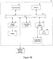
- Figure 3B shows one example of a conventional computer system that can be used as a client computer system or a server computer system or as a web server system. It will also be appreciated that such a computer system can be used to perform many of the functions of an Internet service provider, such as ISP 5.
- the computer system 51 interfaces to external systems through the modem or network interface 53. It will be appreciated that the modem or network interface 53 can be considered to be part of the computer system 51.
- This interface 53 can be an analog modem, ISDN modem, cable modem, token ring interface, satellite transmission interface (e.g. "Direct PC"), or other interfaces for coupling a computer system to other computer systems.
- the computer system 51 includes a processing unit 55, which can be a conventional microprocessor such as an Intel Pentium microprocessor or Motorola Power PC microprocessor.
- Memory 59 is coupled to the processor 55 by a bus 57.
- Memory 59 can be dynamic random access memory (DRAM) and can also include static RAM (SRAM).
- the bus 57 couples the processor 55 to the memory 59 and also to non-volatile storage 65 and to display controller 61 and to the input/output (I/O) controller 67.
- the display controller 61 controls in the conventional manner a display on a display device 63 which can be a cathode ray tube (CRT) or liquid crystal display.
- CTR cathode ray tube
- the input/output devices 69 can include a keyboard, disk drives, printers, a scanner, and other input and output devices, including a mouse or other pointing device.
- the display controller 61 and the I/O controller 67 can be implemented with conventional well known technology.
- a digital image input device 71 can be a digital camera which is coupled to an I/O controller 67 in order to allow images from the digital camera to be input into the computer system 51.
- the non-volatile storage 65 is often a magnetic hard disk, an optical disk, or another form of storage for large amounts of data. Some of this data is often written, by a direct memory access process, into memory 59 during execution of software in the computer system 51.
- computer-readable medium and “machine-readable medium” include any type of storage device that is accessible by the processor 55 and also encompasses a carrier wave that encodes a data signal.
- the computer system 51 is one example of many possible computer systems which have different architectures.
- personal computers based on an Intel microprocessor often have multiple buses, one of which can be an input/output (I/O) bus for the peripherals and one that directly connects the processor 55 and the memory 59 (often referred to as a memory bus).
- the buses are connected together through bridge components that perform any necessary translation due to differing bus protocols.
- Network computers are another type of computer system that can be used as data clients in accordance with the present invention.
- Network computers do not usually include a hard disk or other mass storage, and the executable programs are loaded from a network connection into the memory 59 for execution by the processor 55.
- a Web TV system which is known in the art, is also considered to be a computer system according to the present invention, but it may lack some of the features shown in Figure 3B , such as certain input or output devices.
- a typical computer system will usually include at least a processor, memory, and a bus coupling the memory to the processor.
- the computer system 51 is controlled by operating system software which includes a file management system, such as a disk operating system, which is part of the operating system software.
- a file management system such as a disk operating system
- One example of an operating system software with its associated file management system software is the family of operating systems known as Windows® from Microsoft Corporation of Redmond, Washington, and their associated file management systems.
- the file management system is typically stored in the non-volatile storage 65 and causes the processor 55 to execute the various acts required by the operating system to input and output data and to store data in memory, including storing files on the non-volatile storage 65.
- a teleconferencing system has been described in which a voice conference session can be controlled by a user though a parallel data conference session.
Landscapes
- Engineering & Computer Science (AREA)
- Signal Processing (AREA)
- Multimedia (AREA)
- General Engineering & Computer Science (AREA)
- Computer Vision & Pattern Recognition (AREA)
- Telephonic Communication Services (AREA)
- Data Exchanges In Wide-Area Networks (AREA)
Description
- This invention relates generally to teleconferencing networks, and more particularly to end user control of a teleconferencing network through a data network.
- A portion of the disclosure of this patent document contains material which is subject to copyright protection. The copyright owner has no objection to the facsimile reproduction by anyone of the patent document or the patent disclosure as it appears in the Patent and Trademark Office patent file or records, but otherwise reserves all copyright rights whatsoever. The following notice applies to the software and data as described below and in the drawings hereto: Copyright © 2002, Latitude Communications, Inc., All Rights Reserved.
- A participant in a voice teleconferencing session generally may control his/her participation in the session by pressing key combinations on the telephone key pad, which sends DTMF signals to a conference controller. Alternatively, a menu of available options for the teleconference may be presented on a workstation connected to a data network. When the participant selects one of the options, a data network server sends signals equivalent to the corresponding DTMF signals to the conference controller. However, generally an end user is able to affect only his/her own participation in the conference and is unable to assert control over other participants.
US 4796293 discloses a conferencing system in which a conference coordinator has access to various commands for controlling a conference, including adding a conferee, splitting off a sub-conference, and changing a conferee between "talk" and "listen-only" modes.
US 6148068 discloses a conferencing system that includes a voice processing server and a web server. Conference participants can participate in a web portion of the conference as well as an audio portion. A conference control panel is provided allowing users to input commands that are relayed to the web server. The control panel can be viewed by each participant. - Aspects of the invention are set out in the independent claims. Certain preferred features are set out in the dependent claims.
- In a preferred embodiment, a user connected to a data network controls a parallel teleconference network by sending requests through the data network. The requests are validated against permissions granted to the user and an action associated with a request is performed at the teleconferencing network if the request is validated. A status for a teleconference hosted by the teleconferencing network may be sent when the action is performed or when other changes occur during the teleconference. A voice and/or data message also may be sent to the user(s) that are affected by the action. In one aspect, the allowed actions are presented to the user through the data network. In another aspect, a graphical user interface for controlling the teleconferencing network is presented to the user through the data network.
- The present invention describes systems, clients, servers, methods, and machine-readable media of varying scope. In addition to the aspects of the present invention described in this summary, further aspects of the invention will become apparent by reference to the drawings and by reading the detailed description that follows.
-
-
Figure 1A is a diagram illustrating a system-level overview of an embodiment of the invention; -
Figure 1B is a diagram illustration remote connections for the embodiment ofFigure 1A ; -
Figure 2A is a flowchart of a method to be performed by a data network client according to an embodiment of the invention; -
Figure 2B is a flowchart of a method to be performed by a data network server according to an embodiment of the invention; -
Figures 2C-D are flowcharts of methods to be performed by a teleconferencing network server according to an embodiment of the invention; -
Figure 3A is a diagram of one embodiment of an operating environment suitable for practicing the present invention; and -
Figure 3B is a diagram of one embodiment of a computer system suitable for use in the operating environment ofFigure 3A . - In the following detailed description of embodiments of the invention, reference is made to the accompanying drawings in which like references indicate similar elements, and in which is shown by way of illustration specific embodiments in which the invention may be practiced. These embodiments are described in sufficient detail to enable those skilled in the art to practice the invention, and it is to be understood that other embodiments may be utilized and that logical, mechanical, electrical, functional, and other changes may be made without departing from the scope of the present invention. The following detailed description is, therefore, not to be taken in a limiting sense, and the scope of the present invention is defined only by the appended claims.
- A system level overview of the operation of an exemplary embodiment of the invention is described by reference to
Figure 1A , which illustrates ateleconferencing system 100 consisting of ateleconferencing network server 101 and adata network server 109. Theteleconferencing network server 101 controls a voice network for a teleconference session and a parallel data-based conference, such as may be conducted over the World Wide Web. Thedata network server 109 and theteleconferencing network server 101 may be connected through directly or through a standard computer network topology, such as a local or wide-area network, operating in accordance any communication protocol, and through any communications medium. - The
data network server 109 is coupled to one or more client systems, illustrated generally asdata network client 111, using any standard computer network, protocol and medium. A teleconference participant (user) receives and sends information for the parallel data conference through theclient 111 using, for example, a graphical user interface. When the parallel data conference is web-based, the graphical user interface may implemented as web pages sent from thedata server 109 for presentation to the user through a web browser executing on theclient 111. - In the embodiment illustrated in
Figure 1A , theteleconferencing network server 101 comprises aconference subsystem 103 and avoice subsystem 105. Thevoice subsystem 105 controls the operation of the voice network, illustrated generally asvoice terminal 107, during a teleconferencing session. Thevoice subsystem 105 may be a telephone switch for a PBX (private branch exchange) or PSTN (public switched telephone network) voice network. Thevoice terminal 107 may be a standard telephone set or one with voice-over-IP capability that is connected into thevoice subsystem 105 through the Internet. When a user at thedata network client 111 wishes to control or change the operation of the current teleconferencing session, theconference subsystem 103 receives the user input from thedata network server 109 and sends the appropriate control signals to thevoice subsystem 105. Theconference subsystem 103 is also responsible for setting up and monitoring a teleconference session through thevoice subsystem 103. - The control actions available to all users include temporarily muting, and subsequently un-muting, oneself. When breakout sessions are available, the user may move to a voice breakout room, and optionally a data breakout room. Actions affecting other teleconference participants are restricted to certain users, such as muting the person who is currently talking in the teleconference, muting other people in the teleconference, permanently changing the speaking ability of someone in the teleconference, or renaming a participant. Additional restricted actions include ejecting someone from the teleconference session and the parallel data session, locking the teleconference session, and optionally the parallel data session, from entry by new users, and setting up the teleconference, such as by calling individual people or by instructing the conference subsystem 104 call a set of people.
- An operation, the
data network client 111 receives user input and forwards the input in a message to thedata network server 109 as illustrated byarrow 1. If the input is a control action that is restricted, thedata network server 109 verifies that the particular user has the appropriate level of permission for the action. In one embodiment, the user's permission levels are stored in a user profile created when the user registers for a teleconference session. Assuming the user is permitted to request the action, thedata network server 109 sends a request message to theconference subsystem 103 as illustrated byarrow 2. In an alternate embodiment, the user profiles are stored on theconference subsystem 103 andserver 109 sends the input to theconference subsystem 103 for validation. - The
conference subsystem 103 evaluates the request message and sends the corresponding control signal to thevoice subsystem 105 as illustrated byarrow 3. Theconference subsystem 103 may also send a message to thevoice terminal 107 through thevoice subsystem 105 as illustrated byarrows - The
conference subsystem 103 also receives control information from thevoice subsystem 105 through the connection illustrated asarrow 3, which enables theconference subsystem 103 to update the status of the teleconference session at thedata network client 111 interface. In particular, theconference subsystem 103 informs thedata network server 109 of the current speaker(s) so that information can be presented to the user. - When a teleconference spans great distances, such as multiple countries, two or more teleconferencing network servers may be connected together as illustrated in
Figure 1B .Teleconferencing network server 101 controls thevoice terminals 107 in one region whileteleconferencing network server 121 controls thevoice terminals 127 in a different region. Typically, the teleconference network server in the conference scheduler's region would initiate a call to the other teleconference network server(s) to set up the teleconference. Each participant is connected to the teleconferencing network server nearest them. For example, if theteleconferencing network server 101 is located in New York and theserver 121 is located in London, the participants in the United States and those in the United Kingdom can hold a joint teleconference that requires only a single transatlantic connection between theservers teleconference network servers - While a system level overview of the operation of an exemplary embodiment of the invention has been described, the inventions is not limited to the particular arrangement of components illustrated. For example, the
conference subsystem 103 and thevoice subsystem 105 has been shown and described as separate components for ease in explanation, but one of skill in the art will immediately appreciate that their functions may be embodied in a single component. - Next, the particular methods of the invention are described in terms of computer software with reference to a series of flowcharts. The methods to be performed by a computer constitute computer programs made up of computer-executable instructions illustrated as blocks (acts). Describing the methods by reference to a flowchart enables one skilled in the art to develop such programs including such instructions to carry out the methods on suitably configured computers (the processing unit of the computer executing the instructions from computer-readable media) acting as clients or servers in accordance with the invention. The computer-executable instructions may be written in a computer programming language or may be embodied in firmware logic. If written in a programming language conforming to a recognized standard, such instructions can be executed on a variety of hardware platforms and for interface to a variety of operating systems. In addition, the present invention is not described with reference to any particular programming language. It will be appreciated that a variety of programming languages may be used to implement the teachings of the invention as described herein. Furthermore, it is common in the art to speak of software, in one form or another (e.g., program, procedure, process, application, module, logic...), as taking an action or causing a result. Such expressions are merely a shorthand way of saying that execution of the software by a computer causes the processor of the computer to perform an action or produce a result.
- The method performed by the
data network client 111 is illustrated inFigure 2A and the method performed by thedata network server 109 is illustrated inFigure 2B . Two flowcharts inFigures 2C-D illustrated the methods performed by theteleconference network server 101 and include the functions described above for theconference subsystem 103 and for thevoice subsystem 105. The methods executed by the data network client and data network server are described in terms of a web-based data conference but are equally applicable to other types of data sessions that parallel teleconference sessions. Furthermore, the methods are described as exchanging data in messages but no particular message protocol is implied or required. - Referring first to
Figure 2A , adata client method 200 is executed by a data client upon receipt of input from the user or a message from the data server (block 201). User input is formatted into a message and sent to the data server (block 203) where it is processed as described below in conjunction withFigure 2B . - When the user requests an action be performed on another participant, the user selects the participant, which sends an identifier for the participant to the data server at
block 203. In response, the data server may return an error message if the user does not have permission to perform any action on another person (block 205), or a list specifying the actions permitted to the user (block 209). Themethod 200 outputs any error message to the user atblock 207. The permitted actions are output as web page menu or tool bar atblock 211 and the user is prompted to for a selection. - In one embodiment, the user is assigned a permission level based on the type of the user. For example, a user who is not profiled ("guest") is only allowed to mute/unmute himself/herself, while a profiled user is allowed to temporarily mute others as well. The ability to mute the participant who is currently speaking enables a user to avoid having to listen to extraneous conversations, "music-on-hold," and noise on the line of the other person. Furthermore, allowing a user to control other participants relieves the presenter of the responsibility of moderating the teleconference during the presentation. In addition to changing the speaking ability of other participants, the scheduler of the teleconference is allowed permanently change the speaking ability of participants and to eject a participant from the voice and data sessions when necessary.
- Additional error messages result from the user attempting to enter a locked voice or data conference. The
method 200 may also subsequently prompt the user atblock 211 for other information, such as a telephone number required to call an invitee not currently participating in the teleconference session. Messages regarding the status of the teleconference update the portions of the client's web page, such as tool bars, menus, and participant list (block 213). Various visual indicators may be used to indicate the current characteristics and status of each participant, such as name, speaking ability (e.g., temporarily or permanently muted), participation (e.g., voice-only conference, data-only conference, voice/data breakout room, ejected), current speaker, etc. In another embodiment, all invitees to the teleconference are listed and marked as participating or not. - A
data server method 220 shown inFigure 2B executes on a server controlling a data network providing a parallel data conference session, such as thedata network server 109 inFigure 1A . Themethod 220 receives messages from thedata client method 200 and from methods executing on theteleconference network server 101 that are described in conjunction inFigures 2C-D below. When a message is received, thedata server method 220 determines if the message is from a data client (block 221). If so, themethod 220 determines if the request is permitted (block 223). For example, if the user is attempting to join a locked conference, the request will be denied. The processing atblock 223 includes checking the user's permissions if the request affects another person, such as when the message contains a participant identifier or a call request to an individual, team, or missing conference invitees. Themethod 220 sends an error message to the data client method atblock 225 if the request is not permitted. - Permitted actions are processed at
block 227 to determine if more data is needed, such as, for example, a call request that requires a phone number. Assuming no additional data is needed, a message is sent to the conference server containing the requested action and any required data atblock 231, where it is processed as described further below. Additional data is requested through a web page created by thedata server method 220 and sent to the data client for presentation to the user atblock 229. If the message from theclient method 200 specifies a participant identifier, themethod 220 formats a web page atblock 229 that contains the actions permitted to the user according to the profile and sends the selected action and participant identifier returned by the data client to the teleconference network server atblock 231. - The
data server method 220 also locks and unlocks a parallel data conference session as illustrated atblocks 233 until 239. The voice conference may be locked/unlocked in conjunction with locking/unlocking the data conference as described below with reference toFigure 2C . A web page showing the updated status of the data conference session is sent to all data clients participating in the particular data conference session atblock 249. - If the message received by the
data server method 220 is from the teleconference network server, thedata server method 220 determines if the message is a "now speaking" message containing a list of speakers in the voice conference (block 241). If not, the message is a result message that provides a status of the user's last request and a web page containing the updated status is sent to the data client atblock 243. If the user's original request was to move to a voice breakout room and a data breakout room (block 245), thedata server method 220 moves the client to the requested data breakout room and informs the affected data client of the change atblock 247. The data clients for the other conference participants are sent updated web pages atblock 249. - Returning to block 241, if the message is a "now speaking" message, the list of speakers has changed and the change is reflected in an updated web page sent to the data clients at
block 249. - The functions performed by the conference subsystem and the voice subsystem are illustrated as a
single conference method 250 inFigure 2C , which utilizes a supporting voiceconference call method 253 inFigure 2D . Theconference server method 250 consists of two parallel threads of processing. In one thread, illustrated asblocks 251 until 271, themethod 250 processes messages from thedata server method 220. The other thread, illustrated asblock 273 until 291, monitors a voice conference to determine which participants are speaking. - Upon receipt of a message from the
data server method 220, themethod 250 determines the type of request atblocks blocks Figure 2B . Themethod 250 evaluates other requests are evaluated atblock 263 to determine if the action requested is allowed, i.e. the user may be attempting to join a locked voice conference. An error message is sent to the data server atblock 265 if the action is not allowed for subsequent delivery to the user as previously described inFigures 2A and2B . Allowed actions are performed atblock 267, and a result message is sent to thedata server method 220 atblock 271. An optional voice message may sent to the voice terminal (block 269, shown in phantom) to audibly inform the user of the change, i.e., muted, unmuted, etc. It will be appreciated that the actions atblock 267 that affect the operations of the voice terminals are performed by the components of the teleconferencing network server that controls the voice conference. - Turning now to
Figure 2D , the supportingcall method 253 performed by theconference server method 250 is described. Thecall method 253 may be incorporated into a prior art process that sets up teleconferences or may be implemented as a separate procedure. The embodiment of thecall method 253 illustrated inFigure 2D enables one teleconferencing network server to communicate with other teleconferencing network servers to set up a teleconference, as well as providing support for various call commands requested by the user. - The
call method 253 determines if the user is initiating a multiserver meeting (block 293) and, if so, sets up a multiserver meeting as described below in conjunction withblock 315. Otherwise, themethod 253 dials the primary number for the specified participant(s) atblock 295. If the call is a manual call in which the user wants to talk the other person (block 301), the conference server connects the user to the line (block 303). Subsequently, the called person may elect to join the conference atblock 311. - For an automatic call request, the conference server determines if there is an answer for each of the people called (block 305) and may optionally dial an alternate number if there is no answer (block 307, shown in phantom). If there is an answer, the
method 253 plays a voice message for the person that instructs them to press certain buttons on the voice terminal to join or decline to join the conference. If the user elects to join the conference atblock 311, the corresponding voice line is connected into the conference (block 313). In an alternate embodiment, the caller may also talk to the people called, if desired, before the voice message is played. - Turning now to block 315, a call request for a multiserver meeting includes one or more teleconferencing network server identifiers associated with invitees that connect to servers other than the initiating teleconferencing network server, i.e., the server for the user initiating the meeting. At
block 315, themethod 253 connects the identified teleconferencing network servers to the initiating teleconferencing network server. It will be appreciated that the processing represented byblock 315 includes the operations necessary to couple the teleconferencing network servers through a voice connection and one of skill in the art will understand the required operations without additional explanation. It will also be appreciated thatFigure 2D implies no particular order in which the servers and the participants are connected into the multiserver teleconference. - Returning to
Figure 2C , the processes performed by theconference server method 250 to monitor the voice levels during the voice conference is now described. At conference initialization (block 237), themethod 250 measures the voice levels of the participants in the voice conference (block 275) and creates an initial list of current speakers (as opposed to those who have the ability to speak), i.e. participants whose voice levels exceed a threshold value (block 277). The list of speakers is sent to thedata server method 220 atblock 277. In one embodiment, the list may show multiple current speakers, with the number of speakers determined by system options or defaults. The conference server continues to measure the voice levels during the conference to update the list of speakers (block 279). If a voice signal meets the threshold (block 281) and the corresponding participant is not currently on the list of speakers (block 289), themethod 250 adds the participant's identifier to the list at block 291 and sends the new list to thedata server method 220 atblock 287, which updates the data clients for the users that are participating in the voice conference as previously described. If a voice signal for a participant that is currently on the list falls below the threshold (block 283), the participant's identifier is removed from the list at block 285 and the new list is sent atblock 287. - The particular methods performed by an embodiment of the invention have been described. It will be appreciated that more or fewer processes may be incorporated into the methods illustrated in
Figures 2A-D without departing from the scope of the invention and that no particular order is implied by the arrangement of blocks shown and described herein. Furthermore, it will be appreciated that the functions previously described may be divided among the clients and servers in combinations other than those illustrated and that such alternate combinations are contemplated as within the scope of the invention. - The following description of
Figures 3A-B is intended to provide an overview of computer hardware and other operating components suitable for performing the methods of the invention described above, but is not intended to limit the applicable environments. One of skill in the art will immediately appreciate that the invention can be practiced with other computer system configurations, including hand-held devices, multiprocessor systems, microprocessor-based or programmable consumer electronics, network PCs, minicomputers, mainframe computers, and the like. The invention can also be practiced in distributed computing environments where tasks are performed by remote processing devices that are linked through a communications network. -
Figure 3A shows several computer systems that are coupled together through anetwork 3, such as the Internet. The term "Internet" as used herein refers to a network of networks which uses certain protocols, such as the TCP/IP protocol, and possibly other protocols such as the hypertext transfer protocol (HTTP) for hypertext markup language (HTML) documents that make up the World Wide Web (web). The physical connections of the Internet and the protocols and communication procedures of the Internet are well known to those of skill in the art. Access to theInternet 3 is typically provided by Internet service providers (ISP), such as theISPs client computer systems ISPs web server 9 which is considered to be "on" the Internet. Often these web servers are provided by the ISPs, such asISP 5, although a computer system can be set up and connected to the Internet without that system being also an ISP as is well known in the art. - The
web server 9 is typically at least one computer system which operates as a server computer system and is configured to operate with the protocols of the World Wide Web and is coupled to the Internet. Optionally, theweb server 9 can be part of an ISP which provides access to the Internet for client systems. Theweb server 9 is shown coupled to theserver computer system 11 which itself is coupled toweb content 10, which can be considered a form of a media database. It will be appreciated that while twocomputer systems Figure 3A , theweb server system 9 and theserver computer system 11 can be one computer system having different software components providing the web server functionality and the server functionality provided by theserver computer system 11 which will be described further below. -
Client computer systems web server 9. TheISP 5 provides Internet connectivity to theclient computer system 21 through themodem interface 23 which can be considered part of theclient computer system 21. The client computer system can be a personal computer system, a network computer, a Web TV system, or other such computer system. Similarly, theISP 7 provides Internet connectivity forclient systems Figure 3A , the connections are not the same for these three computer systems.Client computer system 25 is coupled through amodem interface 27 whileclient computer systems Figure 3A shows theinterfaces Client computer systems LAN 33 throughnetwork interfaces LAN 33 is also coupled to agateway computer system 31 which can provide firewall and other Internet related services for the local area network. Thisgateway computer system 31 is coupled to theISP 7 to provide Internet connectivity to theclient computer systems gateway computer system 31 can be a conventional server computer system. Also, theweb server system 9 can be a conventional server computer system. - Alternatively, as well-known, a
server computer system 43 can be directly coupled to theLAN 33 through anetwork interface 45 to providefiles 47 and other services to theclients gateway system 31. -
Figure 3B shows one example of a conventional computer system that can be used as a client computer system or a server computer system or as a web server system. It will also be appreciated that such a computer system can be used to perform many of the functions of an Internet service provider, such asISP 5. Thecomputer system 51 interfaces to external systems through the modem ornetwork interface 53. It will be appreciated that the modem ornetwork interface 53 can be considered to be part of thecomputer system 51. Thisinterface 53 can be an analog modem, ISDN modem, cable modem, token ring interface, satellite transmission interface (e.g. "Direct PC"), or other interfaces for coupling a computer system to other computer systems. Thecomputer system 51 includes aprocessing unit 55, which can be a conventional microprocessor such as an Intel Pentium microprocessor or Motorola Power PC microprocessor.Memory 59 is coupled to theprocessor 55 by abus 57.Memory 59 can be dynamic random access memory (DRAM) and can also include static RAM (SRAM). Thebus 57 couples theprocessor 55 to thememory 59 and also tonon-volatile storage 65 and to displaycontroller 61 and to the input/output (I/O)controller 67. Thedisplay controller 61 controls in the conventional manner a display on adisplay device 63 which can be a cathode ray tube (CRT) or liquid crystal display. The input/output devices 69 can include a keyboard, disk drives, printers, a scanner, and other input and output devices, including a mouse or other pointing device. Thedisplay controller 61 and the I/O controller 67 can be implemented with conventional well known technology. A digitalimage input device 71 can be a digital camera which is coupled to an I/O controller 67 in order to allow images from the digital camera to be input into thecomputer system 51. Thenon-volatile storage 65 is often a magnetic hard disk, an optical disk, or another form of storage for large amounts of data. Some of this data is often written, by a direct memory access process, intomemory 59 during execution of software in thecomputer system 51. One of skill in the art will immediately recognize that the terms "computer-readable medium" and "machine-readable medium" include any type of storage device that is accessible by theprocessor 55 and also encompasses a carrier wave that encodes a data signal. - It will be appreciated that the
computer system 51 is one example of many possible computer systems which have different architectures. For example, personal computers based on an Intel microprocessor often have multiple buses, one of which can be an input/output (I/O) bus for the peripherals and one that directly connects theprocessor 55 and the memory 59 (often referred to as a memory bus). The buses are connected together through bridge components that perform any necessary translation due to differing bus protocols. - Network computers are another type of computer system that can be used as data clients in accordance with the present invention. Network computers do not usually include a hard disk or other mass storage, and the executable programs are loaded from a network connection into the
memory 59 for execution by theprocessor 55. A Web TV system, which is known in the art, is also considered to be a computer system according to the present invention, but it may lack some of the features shown inFigure 3B , such as certain input or output devices. A typical computer system will usually include at least a processor, memory, and a bus coupling the memory to the processor. - It will also be appreciated that the
computer system 51 is controlled by operating system software which includes a file management system, such as a disk operating system, which is part of the operating system software. One example of an operating system software with its associated file management system software is the family of operating systems known as Windows® from Microsoft Corporation of Redmond, Washington, and their associated file management systems. The file management system is typically stored in thenon-volatile storage 65 and causes theprocessor 55 to execute the various acts required by the operating system to input and output data and to store data in memory, including storing files on thenon-volatile storage 65. - A teleconferencing system has been described in which a voice conference session can be controlled by a user though a parallel data conference session.
Claims (31)
- A computerized method for end user control by an end user participating in a teleconference hosted by at least one teleconferencing network server (101) in a teleconferencing network, wherein the teleconferencing network server is connected to a data network server (109) which exchanges messages through a data network with a data network client (111), characterized in that the method comprises, at the data network server (109):receiving, from the data network client, upon selection of another participant of the teleconference, a message including an identifier of the other participant;in response to receiving the message, formatting a web page that contains the actions permitted to the end user according to stored permission level information associated with the end user and sending the web page to the data network client for presenting, to the end user, a choice of actions contained in the web page;receiving, from the data network client, an action which has been selected from the choice of actions; andsending the selected action and the identifier of the other participant to the teleconferencing network server, for changing a characteristic of the other participant in accordance with the selected action.
- The computerized method of claim 1 further comprising:
sending, to the data network client through the data network, an error indicator if no actions are allowed by the permission level information (225). - The computerized method of claim 1, wherein the characteristic is selected from the group consisting of speaking ability, participation, and name.
- The computerized method of claim 1, wherein the identifier is for a current speaker.
- The computerized method of claim 1 further comprising:
sending, to the data network client through the data network, a status for the teleconference. - The computerized method of claim 5, wherein the status is selected from the group consisting of a current speaker, participants, invitees, participant status, a breakout room status, and a conference lock status.
- The computerized method of claim 6, wherein the participant status is selected from the group consisting of speaking, muted, permanently muted, voice only, data only, and voice and data.
- The computerized method of claim 6 further comprising:
monitoring the teleconferencing network to determine the current speaker. - The computerized method of claim 1 further comprising:
sending a message to the participant that is affected by the chosen action. - The computerized method of claim 9, wherein the message is sent through the data network.
- The computerized method of claim 9, wherein the message is sent through the telecommunications network.
- The computerized method of claim 1 further comprising:receiving, from the data network client through the data network, a request to change a characteristic of the end user; andchanging, at the teleconferencing network, the characteristic of the end user in accordance with the request.
- The computerized method of claim 1, wherein the permission level information is based on a type associated with the end user.
- The computerized method of claim 13, wherein the type is selected from the group consisting of guest, profiled user, and conference scheduler.
- The computerized method of claim 1, wherein the data network presents a graphical user interface to the end user to control the teleconferencing network.
- The computerized method of claim 15, wherein the graphical user interface is browser-based.
- The computerized method of claim 1, wherein the data network is a public wide area network.
- The computerized method of claim 1, wherein the data network is virtual private network.
- The computerized method of claim 1, wherein the data network is a local area network.
- The computerized method of claim 1 further comprising:receiving, from the data network client through the data network, an initiation request for the teleconference, the request comprising a plurality of invitees to the teleconference; andconnecting, by the teleconferencing network, the plurality of invitees to the teleconference if allowed by the permission level information of the end user.
- The computerized method of claim 20, wherein at least one of the invitees is connectable through a different teleconferencing network and further comprising:
connecting, by the teleconferencing network, the different teleconferencing network to the teleconference. - The computerized method of claim 1 further comprising:receiving, from data network client through the data network, an identifier for an invitee who is not participating in the teleconference; andconnecting, by the teleconferencing network, the invitee to the teleconference if the invitee elects to join the teleconference.
- A machine-readable medium or a computer program product having executable instructions to cause a machine to perform a method as claimed in any of claims 1 to 22.
- A data network server system (109) arranged to enable end user control by an end user participating in a teleconference hosted by a teleconferencing network server, wherein the teleconferencing network server is connected to the data network server system, the data network server system comprising:a processor connected to a memory through a bus;a network interface connected to the processor through the bus to send and receive messages to and from a data network client (111) through a data network, and to send and receive message to and from the teleconferencing network server (101); and characterized in comprising:a process executed by the processor from the memory to cause the processor to:receive, from the data network client, upon selection of another participant of the teleconference, a message including an identifier of the other participant;in response to receiving the message, format a web page that contains the actions permitted to the end user according to stored permission level information associated with the end user and send the web page to the data network client for presenting, to the end user, a choice of actions contained in the web page;receive, from the data network client, an action which has been selected from the choice of actions; andsend the selected action and the identifier of the other participant to the teleconferencing network server, for changing a characteristic of the other participant in accordance with the selected action.
- The data network server system of claim 24, wherein the process further causes the processor to send an error indicator to the data network client if no actions are allowed by the permission level information.
- The data network server system of claim 24, wherein the process further causes the processor to send a status for the teleconference to the data network client.
- The data network server system of claim 24, wherein the process further causes the processor to send a message to the participant affected by the chosen action.
- The data network server system of claim 24, wherein the process further causes the processor to receive a request to change a characteristics of the end user from data network client, and to send the request to the teleconferencing network server.
- The data network server system of claim 24, wherein the process further causes the processor to present a graphical user interface to the end user to control the teleconferencing network server.
- The data network server system of claim 24, wherein the process further causes the processor to receive an initiation request for the teleconference from the data network client, the request comprising a plurality of invitees to the teleconference, and to send the request to the teleconferencing network server if allowed by the permission level information of the end user.
- The data network server system of claim 24, wherein the process further causes the processor to receive from the data network client an identifier for an invitee who is not participating in the teleconference and to send the identifier to the teleconferencing network server.
Applications Claiming Priority (3)
| Application Number | Priority Date | Filing Date | Title |
|---|---|---|---|
| US150312 | 2002-05-16 | ||
| US10/150,312 US6915331B2 (en) | 2002-05-16 | 2002-05-16 | End user control of a teleconferencing network through a data network |
| PCT/US2003/015285 WO2003098849A2 (en) | 2002-05-16 | 2003-05-16 | End user control of a teleconferencing network through a data network |
Publications (3)
| Publication Number | Publication Date |
|---|---|
| EP1504550A2 EP1504550A2 (en) | 2005-02-09 |
| EP1504550A4 EP1504550A4 (en) | 2006-11-02 |
| EP1504550B1 true EP1504550B1 (en) | 2018-08-22 |
Family
ID=29548329
Family Applications (1)
| Application Number | Title | Priority Date | Filing Date |
|---|---|---|---|
| EP03736618.4A Expired - Lifetime EP1504550B1 (en) | 2002-05-16 | 2003-05-16 | End user control of a teleconferencing network through a data network |
Country Status (6)
| Country | Link |
|---|---|
| US (1) | US6915331B2 (en) |
| EP (1) | EP1504550B1 (en) |
| CN (1) | CN100409208C (en) |
| AU (1) | AU2003237858B2 (en) |
| CA (1) | CA2486357C (en) |
| WO (1) | WO2003098849A2 (en) |
Families Citing this family (36)
| Publication number | Priority date | Publication date | Assignee | Title |
|---|---|---|---|---|
| US7640300B2 (en) * | 2002-06-10 | 2009-12-29 | Microsoft Corporation | Presence and notification system for maintaining and communicating information |
| US20050190706A1 (en) * | 2004-02-26 | 2005-09-01 | Henderson Eric A. | Automatic conferencing service |
| US7113200B2 (en) * | 2004-05-21 | 2006-09-26 | Polycom, Inc. | Method and system for preparing video communication image for wide screen display |
| US7899170B2 (en) | 2005-04-28 | 2011-03-01 | Apple Inc. | Multi-participant conference setup |
| US7949117B2 (en) * | 2005-04-28 | 2011-05-24 | Apple Inc. | Heterogeneous video conferencing |
| US7692682B2 (en) | 2005-04-28 | 2010-04-06 | Apple Inc. | Video encoding in a video conference |
| US7817180B2 (en) * | 2005-04-28 | 2010-10-19 | Apple Inc. | Video processing in a multi-participant video conference |
| US7864209B2 (en) * | 2005-04-28 | 2011-01-04 | Apple Inc. | Audio processing in a multi-participant conference |
| US8861701B2 (en) * | 2005-04-28 | 2014-10-14 | Apple Inc. | Multi-participant conference adjustments |
| US8305939B2 (en) | 2005-10-13 | 2012-11-06 | International Business Machines Corporation | Selective teleconference interruption |
| DK1781054T3 (en) * | 2005-10-28 | 2010-06-21 | Ericsson Telefon Ab L M | Methods and apparatus for push-to-talk service |
| US7746374B2 (en) * | 2006-01-25 | 2010-06-29 | Seiko Epson Corporation | Videoconference data relay server |
| US7716284B2 (en) * | 2006-02-28 | 2010-05-11 | Microsoft Corporation | Subsystem-scoping architecture for breakout rooms in a virtual space |
| US7929679B2 (en) * | 2006-03-21 | 2011-04-19 | Alcatel-Lucent Usa Inc. | Muting conference call hold music |
| JP2007274176A (en) * | 2006-03-30 | 2007-10-18 | Pioneer Electronic Corp | Audio conferencing apparatus, audio confirmation method in audio conference system, and program thereof |
| GB2437785A (en) * | 2006-05-02 | 2007-11-07 | Skype Ltd | Voice over internet protocol (VOIP) group conference communication |
| EP2020813B1 (en) | 2006-05-24 | 2013-04-17 | Huawei Technologies Co., Ltd. | A method, device and system for implementing the session service |
| US8819129B1 (en) | 2006-06-09 | 2014-08-26 | Avaya Inc. | Auto join conference |
| CN101127615B (en) * | 2006-07-06 | 2012-08-08 | 北京艾易信息通信有限责任公司 | A multi-party conference device and multi-party conference system and method based on IMB Lotus Notes |
| CN101127617B (en) * | 2006-07-06 | 2012-08-08 | 北京艾易信息通信有限责任公司 | A multi-party conference device and multi-party conference system and method based on Microsoft Share Point Server |
| CN101127616B (en) * | 2006-07-06 | 2011-02-09 | 北京艾易信息通信有限责任公司 | A multi-party conference device and multi-party conference system and method based on Microsoft Office Communicator |
| US8266535B2 (en) | 2006-09-11 | 2012-09-11 | Broadnet Teleservices, Llc | Teleforum apparatus and method |
| US20080151876A1 (en) * | 2006-12-20 | 2008-06-26 | Wilson Ian A | Serverless peer to peer voice and data over internet protocol communications system |
| CN101325487B (en) * | 2007-06-15 | 2011-11-30 | 中兴通讯股份有限公司 | Method for limiting display of subscriber number in conference business notification message |
| US8167724B2 (en) * | 2007-12-10 | 2012-05-01 | Gary Stephen Shuster | Guest management in an online multi-player virtual reality game |
| US8275108B2 (en) | 2008-02-26 | 2012-09-25 | International Business Machines Corporation | Hierarchal control of teleconferences |
| JP2009239714A (en) * | 2008-03-27 | 2009-10-15 | Fujitsu Ltd | Conference system, conference program, and conference resource allocating method |
| US8369506B2 (en) * | 2009-03-06 | 2013-02-05 | International Business Machines Corporation | Informing a teleconference participant that a person-of-interest has become active within the teleconference |
| JP5282610B2 (en) * | 2009-03-09 | 2013-09-04 | ブラザー工業株式会社 | Video conference device, video conference system, video conference control method, and program for video conference device |
| US8433813B2 (en) | 2010-04-07 | 2013-04-30 | Apple Inc. | Audio processing optimization in a multi-participant conference |
| US8553067B2 (en) | 2010-07-01 | 2013-10-08 | Cisco Technology, Inc. | Capturing and controlling access to muted content from a conference session |
| US8711736B2 (en) | 2010-09-16 | 2014-04-29 | Apple Inc. | Audio processing in a multi-participant conference |
| KR101569863B1 (en) | 2011-05-31 | 2015-11-27 | 구글 인코포레이티드 | Muting participants in a communication session |
| US8743743B1 (en) | 2012-12-18 | 2014-06-03 | Cisco Technology, Inc. | Management of mute and unmute requests during an electronic-conference session |
| US9525848B2 (en) | 2014-05-30 | 2016-12-20 | Highfive Technologies, Inc. | Domain trusted video network |
| CN104618614B (en) * | 2015-01-16 | 2017-12-12 | 四川联友电讯技术有限公司 | The method that simultaneous voice conference system terminates meeting |
Family Cites Families (5)
| Publication number | Priority date | Publication date | Assignee | Title |
|---|---|---|---|---|
| US4796293A (en) * | 1987-12-18 | 1989-01-03 | Communications Network Enhancement Inc. | Enhanced dedicated teleconferencing system |
| US5973724A (en) | 1995-02-24 | 1999-10-26 | Apple Computer, Inc. | Merging multiple teleconferences |
| CA2266921A1 (en) * | 1996-09-25 | 1998-04-02 | Andrew David Mercer | Network-based conference system |
| US6148068A (en) * | 1997-10-20 | 2000-11-14 | Nortel Networks Limited | System for managing an audio conference |
| TW527833B (en) * | 2000-05-19 | 2003-04-11 | Sony Corp | Network conferencing system, participation authorization method and presenting method |
-
2002
- 2002-05-16 US US10/150,312 patent/US6915331B2/en not_active Expired - Lifetime
-
2003
- 2003-05-16 EP EP03736618.4A patent/EP1504550B1/en not_active Expired - Lifetime
- 2003-05-16 CA CA2486357A patent/CA2486357C/en not_active Expired - Fee Related
- 2003-05-16 WO PCT/US2003/015285 patent/WO2003098849A2/en not_active Ceased
- 2003-05-16 CN CNB03811190XA patent/CN100409208C/en not_active Expired - Fee Related
- 2003-05-16 AU AU2003237858A patent/AU2003237858B2/en not_active Ceased
Non-Patent Citations (1)
| Title |
|---|
| None * |
Also Published As
| Publication number | Publication date |
|---|---|
| WO2003098849A2 (en) | 2003-11-27 |
| AU2003237858A1 (en) | 2003-12-02 |
| CN100409208C (en) | 2008-08-06 |
| CN1653433A (en) | 2005-08-10 |
| CA2486357A1 (en) | 2003-11-27 |
| US20030235277A1 (en) | 2003-12-25 |
| EP1504550A4 (en) | 2006-11-02 |
| AU2003237858B2 (en) | 2009-07-23 |
| US6915331B2 (en) | 2005-07-05 |
| CA2486357C (en) | 2014-05-13 |
| WO2003098849A3 (en) | 2004-05-06 |
| EP1504550A2 (en) | 2005-02-09 |
Similar Documents
| Publication | Publication Date | Title |
|---|---|---|
| US6915331B2 (en) | End user control of a teleconferencing network through a data network | |
| US6418214B1 (en) | Network-based conference system | |
| US6501740B1 (en) | System and method for teleconferencing on an internetwork comprising connection-oriented and connectionless networks | |
| US7062025B2 (en) | Internet-enabled conferencing system and method accommodating PSTN and IP traffic | |
| US20040006595A1 (en) | Extended features to conferencing system using a web-based management interface | |
| US6148067A (en) | Anonymous voice communication | |
| US8326927B2 (en) | Method and apparatus for inviting non-rich media endpoints to join a conference sidebar session | |
| US7685235B2 (en) | Method and system for integration of instant messaging and teleconferencing via a telephone network | |
| CA2251154C (en) | System for managing an audio conference | |
| US6961416B1 (en) | Internet-enabled conferencing system and method accommodating PSTN and IP traffic | |
| US20010053213A1 (en) | Teleconferencing system and method | |
| US7653013B1 (en) | Conferencing systems with enhanced capabilities | |
| WO2005101858A1 (en) | Anonymous voice communication | |
| US20130271561A1 (en) | Advanced Video Conference | |
| WO2002078308A1 (en) | System and method for providing simplified conferencing | |
| EP2982095B1 (en) | Real time application programming interface in a telecommunications network | |
| KR20190031671A (en) | System and method for providing audio conference between heterogenious networks | |
| US8358763B2 (en) | Camping on a conference or telephony port | |
| US20080181383A1 (en) | Communication system, server equipment and terminal equipment | |
| JP4903477B2 (en) | Group call server | |
| US20080123633A1 (en) | Server apparatus | |
| KR100586530B1 (en) | How to Open a Multiparty Video Conference Using Computer Telephone Integration | |
| HK1220555B (en) | Real time application programming interface in a telecommunications network |
Legal Events
| Date | Code | Title | Description |
|---|---|---|---|
| PUAI | Public reference made under article 153(3) epc to a published international application that has entered the european phase |
Free format text: ORIGINAL CODE: 0009012 |
|
| 17P | Request for examination filed |
Effective date: 20041110 |
|
| AK | Designated contracting states |
Kind code of ref document: A2 Designated state(s): AT BE BG CH CY CZ DE DK EE ES FI FR GB GR HU IE IT LI LU MC NL PT RO SE SI SK TR |
|
| AX | Request for extension of the european patent |
Extension state: AL LT LV MK |
|
| RIC1 | Information provided on ipc code assigned before grant |
Ipc: 7G 06F 13/00 A |
|
| DAX | Request for extension of the european patent (deleted) | ||
| RAP1 | Party data changed (applicant data changed or rights of an application transferred) |
Owner name: CISCO MANAGED SOLUTIONS, INC. |
|
| A4 | Supplementary search report drawn up and despatched |
Effective date: 20061004 |
|
| RIC1 | Information provided on ipc code assigned before grant |
Ipc: H04M 3/56 20060101AFI20060927BHEP |
|
| 17Q | First examination report despatched |
Effective date: 20090511 |
|
| RAP1 | Party data changed (applicant data changed or rights of an application transferred) |
Owner name: CISCO TECHNOLOGY, INC. |
|
| GRAP | Despatch of communication of intention to grant a patent |
Free format text: ORIGINAL CODE: EPIDOSNIGR1 |
|
| STAA | Information on the status of an ep patent application or granted ep patent |
Free format text: STATUS: GRANT OF PATENT IS INTENDED |
|
| INTG | Intention to grant announced |
Effective date: 20180321 |
|
| GRAS | Grant fee paid |
Free format text: ORIGINAL CODE: EPIDOSNIGR3 |
|
| GRAA | (expected) grant |
Free format text: ORIGINAL CODE: 0009210 |
|
| STAA | Information on the status of an ep patent application or granted ep patent |
Free format text: STATUS: THE PATENT HAS BEEN GRANTED |
|
| AK | Designated contracting states |
Kind code of ref document: B1 Designated state(s): AT BE BG CH CY CZ DE DK EE ES FI FR GB GR HU IE IT LI LU MC NL PT RO SE SI SK TR |
|
| REG | Reference to a national code |
Ref country code: GB Ref legal event code: FG4D |
|
| REG | Reference to a national code |
Ref country code: CH Ref legal event code: EP |
|
| REG | Reference to a national code |
Ref country code: AT Ref legal event code: REF Ref document number: 1033832 Country of ref document: AT Kind code of ref document: T Effective date: 20180915 |
|
| REG | Reference to a national code |
Ref country code: IE Ref legal event code: FG4D |
|
| REG | Reference to a national code |
Ref country code: DE Ref legal event code: R096 Ref document number: 60351417 Country of ref document: DE |
|
| REG | Reference to a national code |
Ref country code: NL Ref legal event code: MP Effective date: 20180822 |
|
| PG25 | Lapsed in a contracting state [announced via postgrant information from national office to epo] |
Ref country code: FI Free format text: LAPSE BECAUSE OF FAILURE TO SUBMIT A TRANSLATION OF THE DESCRIPTION OR TO PAY THE FEE WITHIN THE PRESCRIBED TIME-LIMIT Effective date: 20180822 Ref country code: GR Free format text: LAPSE BECAUSE OF FAILURE TO SUBMIT A TRANSLATION OF THE DESCRIPTION OR TO PAY THE FEE WITHIN THE PRESCRIBED TIME-LIMIT Effective date: 20181123 Ref country code: SE Free format text: LAPSE BECAUSE OF FAILURE TO SUBMIT A TRANSLATION OF THE DESCRIPTION OR TO PAY THE FEE WITHIN THE PRESCRIBED TIME-LIMIT Effective date: 20180822 Ref country code: BG Free format text: LAPSE BECAUSE OF FAILURE TO SUBMIT A TRANSLATION OF THE DESCRIPTION OR TO PAY THE FEE WITHIN THE PRESCRIBED TIME-LIMIT Effective date: 20181122 Ref country code: NL Free format text: LAPSE BECAUSE OF FAILURE TO SUBMIT A TRANSLATION OF THE DESCRIPTION OR TO PAY THE FEE WITHIN THE PRESCRIBED TIME-LIMIT Effective date: 20180822 |
|
| REG | Reference to a national code |
Ref country code: CH Ref legal event code: PK Free format text: BERICHTIGUNGEN |
|
| RIC2 | Information provided on ipc code assigned after grant |
Ipc: H04M 3/56 20060101AFI20060927BHEP |
|
| REG | Reference to a national code |
Ref country code: AT Ref legal event code: MK05 Ref document number: 1033832 Country of ref document: AT Kind code of ref document: T Effective date: 20180822 |
|
| PG25 | Lapsed in a contracting state [announced via postgrant information from national office to epo] |
Ref country code: ES Free format text: LAPSE BECAUSE OF FAILURE TO SUBMIT A TRANSLATION OF THE DESCRIPTION OR TO PAY THE FEE WITHIN THE PRESCRIBED TIME-LIMIT Effective date: 20180822 |
|
| PG25 | Lapsed in a contracting state [announced via postgrant information from national office to epo] |
Ref country code: RO Free format text: LAPSE BECAUSE OF FAILURE TO SUBMIT A TRANSLATION OF THE DESCRIPTION OR TO PAY THE FEE WITHIN THE PRESCRIBED TIME-LIMIT Effective date: 20180822 Ref country code: IT Free format text: LAPSE BECAUSE OF FAILURE TO SUBMIT A TRANSLATION OF THE DESCRIPTION OR TO PAY THE FEE WITHIN THE PRESCRIBED TIME-LIMIT Effective date: 20180822 Ref country code: CZ Free format text: LAPSE BECAUSE OF FAILURE TO SUBMIT A TRANSLATION OF THE DESCRIPTION OR TO PAY THE FEE WITHIN THE PRESCRIBED TIME-LIMIT Effective date: 20180822 Ref country code: AT Free format text: LAPSE BECAUSE OF FAILURE TO SUBMIT A TRANSLATION OF THE DESCRIPTION OR TO PAY THE FEE WITHIN THE PRESCRIBED TIME-LIMIT Effective date: 20180822 Ref country code: EE Free format text: LAPSE BECAUSE OF FAILURE TO SUBMIT A TRANSLATION OF THE DESCRIPTION OR TO PAY THE FEE WITHIN THE PRESCRIBED TIME-LIMIT Effective date: 20180822 |
|
| REG | Reference to a national code |
Ref country code: DE Ref legal event code: R097 Ref document number: 60351417 Country of ref document: DE |
|
| PG25 | Lapsed in a contracting state [announced via postgrant information from national office to epo] |
Ref country code: SK Free format text: LAPSE BECAUSE OF FAILURE TO SUBMIT A TRANSLATION OF THE DESCRIPTION OR TO PAY THE FEE WITHIN THE PRESCRIBED TIME-LIMIT Effective date: 20180822 Ref country code: DK Free format text: LAPSE BECAUSE OF FAILURE TO SUBMIT A TRANSLATION OF THE DESCRIPTION OR TO PAY THE FEE WITHIN THE PRESCRIBED TIME-LIMIT Effective date: 20180822 |
|
| PLBE | No opposition filed within time limit |
Free format text: ORIGINAL CODE: 0009261 |
|
| STAA | Information on the status of an ep patent application or granted ep patent |
Free format text: STATUS: NO OPPOSITION FILED WITHIN TIME LIMIT |
|
| 26N | No opposition filed |
Effective date: 20190523 |
|
| PG25 | Lapsed in a contracting state [announced via postgrant information from national office to epo] |
Ref country code: SI Free format text: LAPSE BECAUSE OF FAILURE TO SUBMIT A TRANSLATION OF THE DESCRIPTION OR TO PAY THE FEE WITHIN THE PRESCRIBED TIME-LIMIT Effective date: 20180822 |
|
| REG | Reference to a national code |
Ref country code: CH Ref legal event code: PL |
|
| PG25 | Lapsed in a contracting state [announced via postgrant information from national office to epo] |
Ref country code: CH Free format text: LAPSE BECAUSE OF NON-PAYMENT OF DUE FEES Effective date: 20190531 Ref country code: MC Free format text: LAPSE BECAUSE OF FAILURE TO SUBMIT A TRANSLATION OF THE DESCRIPTION OR TO PAY THE FEE WITHIN THE PRESCRIBED TIME-LIMIT Effective date: 20180822 Ref country code: LI Free format text: LAPSE BECAUSE OF NON-PAYMENT OF DUE FEES Effective date: 20190531 |
|
| REG | Reference to a national code |
Ref country code: BE Ref legal event code: MM Effective date: 20190531 |
|
| PG25 | Lapsed in a contracting state [announced via postgrant information from national office to epo] |
Ref country code: LU Free format text: LAPSE BECAUSE OF NON-PAYMENT OF DUE FEES Effective date: 20190516 |
|
| PG25 | Lapsed in a contracting state [announced via postgrant information from national office to epo] |
Ref country code: TR Free format text: LAPSE BECAUSE OF FAILURE TO SUBMIT A TRANSLATION OF THE DESCRIPTION OR TO PAY THE FEE WITHIN THE PRESCRIBED TIME-LIMIT Effective date: 20180822 |
|
| PG25 | Lapsed in a contracting state [announced via postgrant information from national office to epo] |
Ref country code: IE Free format text: LAPSE BECAUSE OF NON-PAYMENT OF DUE FEES Effective date: 20190516 |
|
| PG25 | Lapsed in a contracting state [announced via postgrant information from national office to epo] |
Ref country code: BE Free format text: LAPSE BECAUSE OF NON-PAYMENT OF DUE FEES Effective date: 20190531 |
|
| PG25 | Lapsed in a contracting state [announced via postgrant information from national office to epo] |
Ref country code: PT Free format text: LAPSE BECAUSE OF FAILURE TO SUBMIT A TRANSLATION OF THE DESCRIPTION OR TO PAY THE FEE WITHIN THE PRESCRIBED TIME-LIMIT Effective date: 20181222 |
|
| PGFP | Annual fee paid to national office [announced via postgrant information from national office to epo] |
Ref country code: DE Payment date: 20200528 Year of fee payment: 18 |
|
| PGFP | Annual fee paid to national office [announced via postgrant information from national office to epo] |
Ref country code: GB Payment date: 20200527 Year of fee payment: 18 |
|
| PG25 | Lapsed in a contracting state [announced via postgrant information from national office to epo] |
Ref country code: CY Free format text: LAPSE BECAUSE OF FAILURE TO SUBMIT A TRANSLATION OF THE DESCRIPTION OR TO PAY THE FEE WITHIN THE PRESCRIBED TIME-LIMIT Effective date: 20180822 |
|
| PG25 | Lapsed in a contracting state [announced via postgrant information from national office to epo] |
Ref country code: HU Free format text: LAPSE BECAUSE OF FAILURE TO SUBMIT A TRANSLATION OF THE DESCRIPTION OR TO PAY THE FEE WITHIN THE PRESCRIBED TIME-LIMIT; INVALID AB INITIO Effective date: 20030516 |
|
| PGFP | Annual fee paid to national office [announced via postgrant information from national office to epo] |
Ref country code: FR Payment date: 20210510 Year of fee payment: 19 |
|
| REG | Reference to a national code |
Ref country code: DE Ref legal event code: R119 Ref document number: 60351417 Country of ref document: DE |
|
| GBPC | Gb: european patent ceased through non-payment of renewal fee |
Effective date: 20210516 |
|
| PG25 | Lapsed in a contracting state [announced via postgrant information from national office to epo] |
Ref country code: GB Free format text: LAPSE BECAUSE OF NON-PAYMENT OF DUE FEES Effective date: 20210516 Ref country code: DE Free format text: LAPSE BECAUSE OF NON-PAYMENT OF DUE FEES Effective date: 20211201 |
|
| PG25 | Lapsed in a contracting state [announced via postgrant information from national office to epo] |
Ref country code: FR Free format text: LAPSE BECAUSE OF NON-PAYMENT OF DUE FEES Effective date: 20220531 |
|
| P01 | Opt-out of the competence of the unified patent court (upc) registered |
Effective date: 20230525 |