EP1503474A1 - Power management system and method - Google Patents
Power management system and method Download PDFInfo
- Publication number
- EP1503474A1 EP1503474A1 EP04254570A EP04254570A EP1503474A1 EP 1503474 A1 EP1503474 A1 EP 1503474A1 EP 04254570 A EP04254570 A EP 04254570A EP 04254570 A EP04254570 A EP 04254570A EP 1503474 A1 EP1503474 A1 EP 1503474A1
- Authority
- EP
- European Patent Office
- Prior art keywords
- power
- current
- imaging system
- imaging
- power management
- Prior art date
- Legal status (The legal status is an assumption and is not a legal conclusion. Google has not performed a legal analysis and makes no representation as to the accuracy of the status listed.)
- Ceased
Links
Images

Classifications
-
- H—ELECTRICITY
- H02—GENERATION; CONVERSION OR DISTRIBUTION OF ELECTRIC POWER
- H02J—CIRCUIT ARRANGEMENTS OR SYSTEMS FOR SUPPLYING OR DISTRIBUTING ELECTRIC POWER; SYSTEMS FOR STORING ELECTRIC ENERGY
- H02J3/00—Circuit arrangements for ac mains or ac distribution networks
- H02J3/12—Circuit arrangements for ac mains or ac distribution networks for adjusting voltage in ac networks by changing a characteristic of the network load
- H02J3/14—Circuit arrangements for ac mains or ac distribution networks for adjusting voltage in ac networks by changing a characteristic of the network load by switching loads on to, or off from, network, e.g. progressively balanced loading
-
- H—ELECTRICITY
- H02—GENERATION; CONVERSION OR DISTRIBUTION OF ELECTRIC POWER
- H02J—CIRCUIT ARRANGEMENTS OR SYSTEMS FOR SUPPLYING OR DISTRIBUTING ELECTRIC POWER; SYSTEMS FOR STORING ELECTRIC ENERGY
- H02J7/00—Circuit arrangements for charging or depolarising batteries or for supplying loads from batteries
- H02J7/0068—Battery or charger load switching, e.g. concurrent charging and load supply
-
- H—ELECTRICITY
- H02—GENERATION; CONVERSION OR DISTRIBUTION OF ELECTRIC POWER
- H02J—CIRCUIT ARRANGEMENTS OR SYSTEMS FOR SUPPLYING OR DISTRIBUTING ELECTRIC POWER; SYSTEMS FOR STORING ELECTRIC ENERGY
- H02J9/00—Circuit arrangements for emergency or stand-by power supply, e.g. for emergency lighting
- H02J9/04—Circuit arrangements for emergency or stand-by power supply, e.g. for emergency lighting in which the distribution system is disconnected from the normal source and connected to a standby source
- H02J9/06—Circuit arrangements for emergency or stand-by power supply, e.g. for emergency lighting in which the distribution system is disconnected from the normal source and connected to a standby source with automatic change-over, e.g. UPS systems
- H02J9/061—Circuit arrangements for emergency or stand-by power supply, e.g. for emergency lighting in which the distribution system is disconnected from the normal source and connected to a standby source with automatic change-over, e.g. UPS systems for DC powered loads
-
- H—ELECTRICITY
- H02—GENERATION; CONVERSION OR DISTRIBUTION OF ELECTRIC POWER
- H02J—CIRCUIT ARRANGEMENTS OR SYSTEMS FOR SUPPLYING OR DISTRIBUTING ELECTRIC POWER; SYSTEMS FOR STORING ELECTRIC ENERGY
- H02J2310/00—The network for supplying or distributing electric power characterised by its spatial reach or by the load
- H02J2310/50—The network for supplying or distributing electric power characterised by its spatial reach or by the load for selectively controlling the operation of the loads
- H02J2310/56—The network for supplying or distributing electric power characterised by its spatial reach or by the load for selectively controlling the operation of the loads characterised by the condition upon which the selective controlling is based
- H02J2310/58—The condition being electrical
- H02J2310/60—Limiting power consumption in the network or in one section of the network, e.g. load shedding or peak shaving
-
- Y—GENERAL TAGGING OF NEW TECHNOLOGICAL DEVELOPMENTS; GENERAL TAGGING OF CROSS-SECTIONAL TECHNOLOGIES SPANNING OVER SEVERAL SECTIONS OF THE IPC; TECHNICAL SUBJECTS COVERED BY FORMER USPC CROSS-REFERENCE ART COLLECTIONS [XRACs] AND DIGESTS
- Y02—TECHNOLOGIES OR APPLICATIONS FOR MITIGATION OR ADAPTATION AGAINST CLIMATE CHANGE
- Y02B—CLIMATE CHANGE MITIGATION TECHNOLOGIES RELATED TO BUILDINGS, e.g. HOUSING, HOUSE APPLIANCES OR RELATED END-USER APPLICATIONS
- Y02B70/00—Technologies for an efficient end-user side electric power management and consumption
- Y02B70/30—Systems integrating technologies related to power network operation and communication or information technologies for improving the carbon footprint of the management of residential or tertiary loads, i.e. smart grids as climate change mitigation technology in the buildings sector, including also the last stages of power distribution and the control, monitoring or operating management systems at local level
- Y02B70/3225—Demand response systems, e.g. load shedding, peak shaving
-
- Y—GENERAL TAGGING OF NEW TECHNOLOGICAL DEVELOPMENTS; GENERAL TAGGING OF CROSS-SECTIONAL TECHNOLOGIES SPANNING OVER SEVERAL SECTIONS OF THE IPC; TECHNICAL SUBJECTS COVERED BY FORMER USPC CROSS-REFERENCE ART COLLECTIONS [XRACs] AND DIGESTS
- Y04—INFORMATION OR COMMUNICATION TECHNOLOGIES HAVING AN IMPACT ON OTHER TECHNOLOGY AREAS
- Y04S—SYSTEMS INTEGRATING TECHNOLOGIES RELATED TO POWER NETWORK OPERATION, COMMUNICATION OR INFORMATION TECHNOLOGIES FOR IMPROVING THE ELECTRICAL POWER GENERATION, TRANSMISSION, DISTRIBUTION, MANAGEMENT OR USAGE, i.e. SMART GRIDS
- Y04S20/00—Management or operation of end-user stationary applications or the last stages of power distribution; Controlling, monitoring or operating thereof
- Y04S20/20—End-user application control systems
- Y04S20/222—Demand response systems, e.g. load shedding, peak shaving
-
- Y—GENERAL TAGGING OF NEW TECHNOLOGICAL DEVELOPMENTS; GENERAL TAGGING OF CROSS-SECTIONAL TECHNOLOGIES SPANNING OVER SEVERAL SECTIONS OF THE IPC; TECHNICAL SUBJECTS COVERED BY FORMER USPC CROSS-REFERENCE ART COLLECTIONS [XRACs] AND DIGESTS
- Y04—INFORMATION OR COMMUNICATION TECHNOLOGIES HAVING AN IMPACT ON OTHER TECHNOLOGY AREAS
- Y04S—SYSTEMS INTEGRATING TECHNOLOGIES RELATED TO POWER NETWORK OPERATION, COMMUNICATION OR INFORMATION TECHNOLOGIES FOR IMPROVING THE ELECTRICAL POWER GENERATION, TRANSMISSION, DISTRIBUTION, MANAGEMENT OR USAGE, i.e. SMART GRIDS
- Y04S20/00—Management or operation of end-user stationary applications or the last stages of power distribution; Controlling, monitoring or operating thereof
- Y04S20/20—End-user application control systems
- Y04S20/248—UPS systems or standby or emergency generators
Definitions
- the present invention generally relates to power management.
- the present invention relates to intelligent power management and control in an imaging system.
- Imaging systems such as x-ray imaging systems, produce images through emission of rays, waves, particles, and radiation, for example.
- emissions may be facilitated by a power source, such as a battery.
- a power source such as a battery.
- x-rays are generated using a battery power source. As x-rays are generated, the battery is depleted. Therefore, the battery is recharged by the imaging system to allow for continued imaging.
- Present imaging systems budget power to a battery charger based on a worst-case current and/or power consumption. That is, power is routed to the battery charger assuming that maximum current is allocated to main system power and all other system components. Current and/or power allocation in present imaging systems is a static allocation. Limits on battery current and battery recharge rate limit the number of images that may be generated.
- a power cord may be rated at a capacity of 15 or 20 amps, for example, at a rated voltage, such as 110 V or 120 V.
- a standard wall plug for example, is rated at 15 amps and 120 volts. It is desirable to keep power consumption within the rated capacity. However, some systems need more power to operate than is available for 15 or 20 amp service at 120 volts, based on a static power allocation. Therefore, a system which manages power consumption within a rated cord capacity would be highly desirable.
- a system and method that dynamically allocates power in a system based on usage and availability would be highly desirable.
- the adaptable power system includes a measurement unit for measuring current and/or voltage in an imaging system, a main system power for providing power to the imaging system for core system functions, a battery charger for recharging a battery used for imaging, and a power controller for allocating power among the main system power and the battery charger based on a power measurement from the measurement unit.
- the measurement unit measures current and/or voltage at a plurality of points in the imaging system.
- the power controller may allocate remaining power to the battery charger after main system power has been allocated.
- the system may also include at least one component providing additional function in the imaging system.
- the power controller may allocate power among the component(s).
- the power controller may dynamically allocate power within a current, voltage, and/or power limit.
- the method includes measuring current and/or voltage input in an imaging system and allocating power in the imaging system based on a system configuration and the current input in the imaging system.
- the method may also include measuring current and/or voltage at a plurality of locations in the imaging system.
- the method may also include dynamically allocating power based on immediate system usage. Power may be re-allocated based on a change in configuration and/or a current consumption exceeding a predefined limit. Remaining current may be allocated to a battery charger.
- the method includes maintaining at least a minimum level of power for basic imaging system functions.
- the method may also include controlling an amount of current drawn by components in the imaging system.
- a power management system for an imaging system includes a power input providing power to an imaging system, at least one measurement unit for measuring current and/or voltage in the imaging system, and a power management controller allocating available power among components in the imaging system.
- the power management controller may allow a battery for the imaging system to charge at a maximum rate based on current usage by the components in the imaging system.
- the measurement unit(s) may measure a voltage and a current for the power provided to the imaging system.
- the power management controller may control current drawn by the components in the imaging system.
- the system may also include a limit sensor for detecting when current and/or voltage usage exceeds a certain power limit.
- the system may include at least one switching unit controlled by the power management controller. The switching unit(s) control an amount of power routed to components in the imaging system.
- Certain embodiments of the present invention may be used with a variety of imaging systems, such as x-ray, ultrasound, computed tomography (CT), magnetic resonance (MR), electron beam tomography (EBT), positron emission tomography (PET), and single photon emission computed tomography (SPECT) imaging systems.
- imaging systems such as x-ray, ultrasound, computed tomography (CT), magnetic resonance (MR), electron beam tomography (EBT), positron emission tomography (PET), and single photon emission computed tomography (SPECT) imaging systems.
- CT computed tomography
- MR magnetic resonance
- EBT electron beam tomography
- PET positron emission tomography
- SPECT single photon emission computed tomography
- Certain embodiments may be used with mobile and/or stationary imaging systems.
- Certain embodiments have application in medical fields as well as industrial and security fields, for example. For purposes of illustration only, certain embodiments are described in the context of a mobile x-ray imaging system.
- FIG. 1 illustrates a mobile x-ray system with adaptive power management 100 used in accordance with an embodiment of the present invention.
- the system 100 includes a power input 105, an intelligent power controller 110, measurement units 120-124, switching units 130-133, main system power 140, a battery charger 150, and other components such as a computer 160, a motor 170, and a printer 180.
- the measurement units 120-124 transmit data to the intelligent power controller 110.
- the power controller 110 controls the switching units 130-133, which route current to components such as the battery charger 150, the computer 160, the motor 170, and the printer 180.
- the power controller 110 may be implemented in general purpose (such as a general purpose computer) or dedicated hardware or may be implemented in software, for example.
- the power controller 110 allocates current from the power input 105 to the components of the system 100 based on current and/or voltage measurements.
- the power controller 110 receives voltage and/or current information from the measurement units 120-124 associated with the components of the system 100.
- the power controller 110 determines current allocation based on the measurement information. Based on the measurement information, the power controller 110 controls the switching units 130-133 to provide current.
- the measurement units 120-124 measure current and/or voltage at various points in the system 100 to determine current consumption.
- the measurement units 120-124 are located at each component of the system 100.
- current and voltage may be measured at the power input 105.
- the measurement units 120-124 include root-mean-squared (RMS) measurement devices.
- the RMS measurement devices measure current and/or voltage.
- the RMS measurement device measures current and/or voltage because current and voltage may not necessarily be in phase with each other. Additionally, the RMS measurement device may measure current and/or voltage because current consumption increases if 120 V AC inlet voltage decreases.
- voltage is constant and current is "on” or "off” depending upon component use.
- a real power load may be calculated from the power input 105, such as the wall outlet AC power input.
- RMS measurement devices may measure current and voltage at individual components of the system 100.
- one or more of the measurement units 120-124 may include a current transformer (a few turns of wire in a coil, for example), driving a load to measure voltage, an inline resistor, an/or other current or voltage measuring devices.
- the measurement units 120-124 may obtain isolated current/voltage measurements in the system 100.
- a power cord is rated at a capacity of 15 or 20 amps at a rated voltage of 120 V at a frequency of 60 Hertz. European systems may be rated at 220 or 110 volts at 50 Hertz.
- the measurement units 120-124 transmit inlet 105 voltage and current measurements, main system power 140, motor 170 power, computer 160 power, printer 180 power, and/or other accessory power, for example, to the power controller 110.
- the power controller 110 controls the battery charger 150 rate and power/current to components such as the motor 170, the computer 160, the printer 180, and other options or accessories so that the system 100 operates with desired functions without exceeding power cord limits.
- the power controller 110 may also control power to an uninterruptible power supply (UPS) or a UPS battery charger for the system 100 as well.
- UPS uninterruptible power supply
- the measurement units 120-124 may collect data for the UPS and/or UPS charger.
- the UPS may help ensure that main system power 140 is stable.
- the power controller 110 activates the switching units 130-133 or transmits commands to the switching units according to current demand and/or power availability in the system 100.
- a current limit for a component in the system 100 is programmable.
- the power controller 110 may determine component current limits based on input power 105 and other constraints, for example, or the current limits may be programmed or preset, for example.
- the power controller 110 may program the switching units 130-133 to pull a certain amount of current based on the current limits and current/voltage measurements.
- the power controller 100 may also turn the switching units 130-133 on or off. For example, the printer 180 and/or the computer 160 may be turned off when not in use to provide more current for imaging and battery charging.
- Turning the switching units 130-133 on or off may turn the component connected to the switching unit on or off.
- the power controller 110 controls the power/current pulled by the switching units 130-133 to supply components, such as the battery charger 150, computer 160, motor 170, and printer 180, for example.
- main system power 140 may not be turned off or shut down by the power controller 110 so that a basic amount of power is provided to maintain basic system functions.
- the power controller 110 may allow a higher power system 100 to operate within a 15 or 20 amp power cord rating at a rated voltage (120 volts, for example).
- the measurement units 120-124 monitor actual current consumption in the system 100.
- the power controller 110 may remove or reduce available current to components not in use at the moment and re-allocate the power to components in use at the moment and/or increase the battery charger 150 current.
- the power controller 110 allows the current demands of the system 100 to be dynamically met based on present circumstances and operations.
- a user of the system 100 configures the system 100 or selects a configuration, and the power controller 110 determines whether the configuration is possible given constraints on maximum current draw.
- the power controller 110 may configure the system 100 accordingly.
- the system 100 may also include a limit sensor.
- the limit sensor may be incorporated in the power controller 110 or located elsewhere in the system 100. If current consumption exceeds the cap limit, then the limit sensor helps ensure that the limit is not exceeded for more than a certain amount of time (a surge period, for example).
- the limit sensor may be triggered by the power controller 110 or another external source or triggered autonomously based on current/voltage measurements.
- the limit sensor detects excess current over a defined period of time. If current drawn by the system 100 exceeds the power cord limit for more than the defined period of time, then the limit sensor may trigger a system 100 or component shutdown.
- the limit sensor may be implemented as part of the power controller 110 or may be a separate controller or a state machine on a field programmable gate array (FPGA) for example.
- the limit sensor may add a safety shutoff to the system 100.
- the power controller 110 may also have hardware and/or software checks to ensure safety and proper current consumption.
- a user connects the system 100, such as a mobile x-ray system, to a power source, such as a wall AC power outlet.
- the power controller 110 determines the cord current capacity limits for the input power 105 and the system 100.
- the measurement units 120-124 measure current and voltage at the input power 105, main system power 140, battery charger 150, computer 160, motor 170, printer 180.
- a user selects a configuration for the system 100, such as fluoroscopic imaging.
- the power controller 110 allocates power to components in the system 100 based on available current and the user configuration. If the user attempts to turn on the computer 160 during imaging, the power controller 110 manages power to the system 100 and controls the switching units 130-133 accordingly.
- the power controller 110 may reduce current to or deactivate the computer 160. Similarly, if a user attempts to print using the printer 180 during imaging and insufficient current is available or usage would exceed current limits, then the power controller 110 temporarily disables the printer 180. Preferably, the power controller 110 maintains main system power 140 and at least a minimal level of current to the battery charger 150 to continue recharging the battery for imaging.
- the computer 160 may remain on to run software used for intelligent power control and other imaging system functions. If additional power is routed to provide main system power 140, the battery charging rate is reduced rather than deactivating the computer 160.
- Certain embodiments of the present invention monitor actual current consumption and control power that is not used by a component at a certain time.
- Certain embodiments represent a dynamic, adaptable power allocation and management system 100.
- Certain embodiments dynamically allocate available current to the battery charger up to the allowed limits 150.
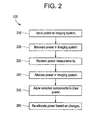
- FIG. 2 illustrates a flow diagram for a method 200 for dynamic power management used in accordance with an embodiment of the present invention.
- the power may be AC or DC power from a power source, such as a wall outlet or other power source.
- a power source such as a wall outlet or other power source.
- current and/or voltage is measured at various points in the imaging system and attached accessories.
- Current may be measured at the power input and/or at a plurality of points within the system, such as at power connections (e.g., a switch) to components and options in the system.
- Components and options may include a computer, a printer, a motor, and a battery charger, for example.
- an adaptable power controller such as the power controller 110 receives imaging system current measurements. Then, at step 240, the power controller 110 allocates power to the imaging system and components based on the current measurements, configuration information, and other system factors, for example. For example, the power controller 110 allocates power to system components based on a selected imaging mode of operation, a number of components in use, component current consumption, available input current, and cord current capacity limits, for example.
- step 250 switches or other current routing units allow selected components in the system to draw current, as determined by the adaptable power controller.
- the adaptable power controller re-allocates power in the imaging system. Additionally, if a current limit is reached, then the power controller re-allocates power in the imaging system.
- certain embodiments of the present invention provide a method and system for dynamic power management in an imaging system.
- the system and method may be used with a plurality of imaging system modalities and platforms.
- Certain embodiments provide maximum power to battery recharging in view of actual system power requirements and consumption.
- Certain embodiments allow power allocation to be adjusted dynamically based on current usage and configuration of an imaging system.
- Certain embodiments measure current, voltage, and/or power to allocate input current.
- Certain embodiments allow power to be allocated and managed within safety limits for input current and/or voltage and cords in the system.
- Certain embodiments allow intelligent power management of an imaging system not limited by a worst case current scenario.
Landscapes
- Engineering & Computer Science (AREA)
- Power Engineering (AREA)
- Business, Economics & Management (AREA)
- Emergency Management (AREA)
- Charge And Discharge Circuits For Batteries Or The Like (AREA)
- Magnetic Resonance Imaging Apparatus (AREA)
- Secondary Cells (AREA)
- Apparatus For Radiation Diagnosis (AREA)
Abstract
Description
- The present invention generally relates to power management. In particular, the present invention relates to intelligent power management and control in an imaging system.
- Imaging systems, such as x-ray imaging systems, produce images through emission of rays, waves, particles, and radiation, for example. In many imaging systems, emissions may be facilitated by a power source, such as a battery. In an x-ray system, for example, x-rays are generated using a battery power source. As x-rays are generated, the battery is depleted. Therefore, the battery is recharged by the imaging system to allow for continued imaging.
- Present imaging systems budget power to a battery charger based on a worst-case current and/or power consumption. That is, power is routed to the battery charger assuming that maximum current is allocated to main system power and all other system components. Current and/or power allocation in present imaging systems is a static allocation. Limits on battery current and battery recharge rate limit the number of images that may be generated.
- However, current and/or power consumption varies by use and duration. For example, printers draw more power when printing than when idle. Current drawn by motors varies by use and direction of the motor. Therefore, a system that adapts to changing power consumption would be highly desirable.
- A power cord may be rated at a capacity of 15 or 20 amps, for example, at a rated voltage, such as 110 V or 120 V. A standard wall plug, for example, is rated at 15 amps and 120 volts. It is desirable to keep power consumption within the rated capacity. However, some systems need more power to operate than is available for 15 or 20 amp service at 120 volts, based on a static power allocation. Therefore, a system which manages power consumption within a rated cord capacity would be highly desirable.
- Therefore, a need exists for improved power management in an imaging system. A system and method that dynamically allocates power in a system based on usage and availability would be highly desirable.
- Certain embodiments of the present invention provide a method and system for dynamic current and power management in an imaging system. Certain embodiments may be used with a plurality of imaging systems and imaging modalities. In a certain embodiment, the adaptable power system includes a measurement unit for measuring current and/or voltage in an imaging system, a main system power for providing power to the imaging system for core system functions, a battery charger for recharging a battery used for imaging, and a power controller for allocating power among the main system power and the battery charger based on a power measurement from the measurement unit.
- In an embodiment, the measurement unit measures current and/or voltage at a plurality of points in the imaging system. The power controller may allocate remaining power to the battery charger after main system power has been allocated. The system may also include at least one component providing additional function in the imaging system. The power controller may allocate power among the component(s). The power controller may dynamically allocate power within a current, voltage, and/or power limit.
- In a certain embodiment, the method includes measuring current and/or voltage input in an imaging system and allocating power in the imaging system based on a system configuration and the current input in the imaging system. The method may also include measuring current and/or voltage at a plurality of locations in the imaging system. The method may also include dynamically allocating power based on immediate system usage. Power may be re-allocated based on a change in configuration and/or a current consumption exceeding a predefined limit. Remaining current may be allocated to a battery charger. In an embodiment, the method includes maintaining at least a minimum level of power for basic imaging system functions. The method may also include controlling an amount of current drawn by components in the imaging system.
- In a certain embodiment, a power management system for an imaging system includes a power input providing power to an imaging system, at least one measurement unit for measuring current and/or voltage in the imaging system, and a power management controller allocating available power among components in the imaging system. The power management controller may allow a battery for the imaging system to charge at a maximum rate based on current usage by the components in the imaging system. The measurement unit(s) may measure a voltage and a current for the power provided to the imaging system. The power management controller may control current drawn by the components in the imaging system. The system may also include a limit sensor for detecting when current and/or voltage usage exceeds a certain power limit. Additionally, the system may include at least one switching unit controlled by the power management controller. The switching unit(s) control an amount of power routed to components in the imaging system.
- Embodiments of the invention will now be described, by way of example, with reference to the accompanying drawings, in which:
- Figure 1 illustrates a mobile x-ray system with adaptive power management used in accordance with an embodiment of the present invention.
- Figure 2 illustrates a flow diagram for a method for dynamic power management used in accordance with an embodiment of the present invention.
-
- Certain embodiments of the present invention may be used with a variety of imaging systems, such as x-ray, ultrasound, computed tomography (CT), magnetic resonance (MR), electron beam tomography (EBT), positron emission tomography (PET), and single photon emission computed tomography (SPECT) imaging systems. Certain embodiments may be used with mobile and/or stationary imaging systems. Certain embodiments have application in medical fields as well as industrial and security fields, for example. For purposes of illustration only, certain embodiments are described in the context of a mobile x-ray imaging system.
- Figure 1 illustrates a mobile x-ray system with
adaptive power management 100 used in accordance with an embodiment of the present invention. Thesystem 100 includes apower input 105, anintelligent power controller 110, measurement units 120-124, switching units 130-133,main system power 140, abattery charger 150, and other components such as acomputer 160, amotor 170, and aprinter 180. The measurement units 120-124 transmit data to theintelligent power controller 110. Thepower controller 110 controls the switching units 130-133, which route current to components such as thebattery charger 150, thecomputer 160, themotor 170, and theprinter 180. - The
power controller 110 may be implemented in general purpose (such as a general purpose computer) or dedicated hardware or may be implemented in software, for example. Thepower controller 110 allocates current from thepower input 105 to the components of thesystem 100 based on current and/or voltage measurements. Thepower controller 110 receives voltage and/or current information from the measurement units 120-124 associated with the components of thesystem 100. Thepower controller 110 determines current allocation based on the measurement information. Based on the measurement information, thepower controller 110 controls the switching units 130-133 to provide current. - The measurement units 120-124 measure current and/or voltage at various points in the
system 100 to determine current consumption. In an embodiment, the measurement units 120-124 are located at each component of thesystem 100. In an alternative embodiment, current and voltage may be measured at thepower input 105. - In an embodiment, the measurement units 120-124 include root-mean-squared (RMS) measurement devices. The RMS measurement devices measure current and/or voltage. In an embodiment, the RMS measurement device measures current and/or voltage because current and voltage may not necessarily be in phase with each other. Additionally, the RMS measurement device may measure current and/or voltage because current consumption increases if 120 V AC inlet voltage decreases. In an embodiment, voltage is constant and current is "on" or "off" depending upon component use. A real power load may be calculated from the
power input 105, such as the wall outlet AC power input. For more accurate measurement and power management, RMS measurement devices may measure current and voltage at individual components of thesystem 100. - Alternatively, one or more of the measurement units 120-124 may include a current transformer (a few turns of wire in a coil, for example), driving a load to measure voltage, an inline resistor, an/or other current or voltage measuring devices. The measurement units 120-124 may obtain isolated current/voltage measurements in the
system 100. - In an embodiment, a power cord is rated at a capacity of 15 or 20 amps at a rated voltage of 120 V at a frequency of 60 Hertz. European systems may be rated at 220 or 110 volts at 50 Hertz. In an embodiment, the measurement units 120-124 transmit
inlet 105 voltage and current measurements,main system power 140,motor 170 power,computer 160 power,printer 180 power, and/or other accessory power, for example, to thepower controller 110. Thepower controller 110 controls thebattery charger 150 rate and power/current to components such as themotor 170, thecomputer 160, theprinter 180, and other options or accessories so that thesystem 100 operates with desired functions without exceeding power cord limits. - The
power controller 110 may also control power to an uninterruptible power supply (UPS) or a UPS battery charger for thesystem 100 as well. The measurement units 120-124 may collect data for the UPS and/or UPS charger. The UPS may help ensure thatmain system power 140 is stable. - The
power controller 110 activates the switching units 130-133 or transmits commands to the switching units according to current demand and/or power availability in thesystem 100. In an embodiment, a current limit for a component in thesystem 100 is programmable. Thepower controller 110 may determine component current limits based oninput power 105 and other constraints, for example, or the current limits may be programmed or preset, for example. Thepower controller 110 may program the switching units 130-133 to pull a certain amount of current based on the current limits and current/voltage measurements. Thepower controller 100 may also turn the switching units 130-133 on or off. For example, theprinter 180 and/or thecomputer 160 may be turned off when not in use to provide more current for imaging and battery charging. Turning the switching units 130-133 on or off may turn the component connected to the switching unit on or off. Thepower controller 110 controls the power/current pulled by the switching units 130-133 to supply components, such as thebattery charger 150,computer 160,motor 170, andprinter 180, for example. In an embodiment,main system power 140 may not be turned off or shut down by thepower controller 110 so that a basic amount of power is provided to maintain basic system functions. - The
power controller 110 may allow ahigher power system 100 to operate within a 15 or 20 amp power cord rating at a rated voltage (120 volts, for example). The measurement units 120-124 monitor actual current consumption in thesystem 100. Thepower controller 110 may remove or reduce available current to components not in use at the moment and re-allocate the power to components in use at the moment and/or increase thebattery charger 150 current. Thepower controller 110 allows the current demands of thesystem 100 to be dynamically met based on present circumstances and operations. In an embodiment, a user of thesystem 100 configures thesystem 100 or selects a configuration, and thepower controller 110 determines whether the configuration is possible given constraints on maximum current draw. Thepower controller 110 may configure thesystem 100 accordingly. - The
system 100 may also include a limit sensor. The limit sensor may be incorporated in thepower controller 110 or located elsewhere in thesystem 100. If current consumption exceeds the cap limit, then the limit sensor helps ensure that the limit is not exceeded for more than a certain amount of time (a surge period, for example). The limit sensor may be triggered by thepower controller 110 or another external source or triggered autonomously based on current/voltage measurements. The limit sensor detects excess current over a defined period of time. If current drawn by thesystem 100 exceeds the power cord limit for more than the defined period of time, then the limit sensor may trigger asystem 100 or component shutdown. The limit sensor may be implemented as part of thepower controller 110 or may be a separate controller or a state machine on a field programmable gate array (FPGA) for example. The limit sensor may add a safety shutoff to thesystem 100. Thepower controller 110 may also have hardware and/or software checks to ensure safety and proper current consumption. - In operation, for example, a user connects the
system 100, such as a mobile x-ray system, to a power source, such as a wall AC power outlet. Thepower controller 110 determines the cord current capacity limits for theinput power 105 and thesystem 100. The measurement units 120-124 measure current and voltage at theinput power 105,main system power 140,battery charger 150,computer 160,motor 170,printer 180. A user selects a configuration for thesystem 100, such as fluoroscopic imaging. Thepower controller 110 allocates power to components in thesystem 100 based on available current and the user configuration. If the user attempts to turn on thecomputer 160 during imaging, thepower controller 110 manages power to thesystem 100 and controls the switching units 130-133 accordingly. If insufficient current is available to providemain system power 140 for fluoroscopic x-ray imaging, then thepower controller 110 may reduce current to or deactivate thecomputer 160. Similarly, if a user attempts to print using theprinter 180 during imaging and insufficient current is available or usage would exceed current limits, then thepower controller 110 temporarily disables theprinter 180. Preferably, thepower controller 110 maintainsmain system power 140 and at least a minimal level of current to thebattery charger 150 to continue recharging the battery for imaging. - Alternatively, the
computer 160 may remain on to run software used for intelligent power control and other imaging system functions. If additional power is routed to providemain system power 140, the battery charging rate is reduced rather than deactivating thecomputer 160. - Thus certain embodiments of the present invention monitor actual current consumption and control power that is not used by a component at a certain time. Certain embodiments represent a dynamic, adaptable power allocation and
management system 100. Certain embodiments dynamically allocate available current to the battery charger up to the allowed limits 150. - Figure 2 illustrates a flow diagram for a
method 200 for dynamic power management used in accordance with an embodiment of the present invention. First, atstep 210, power is input to an imaging system. The power may be AC or DC power from a power source, such as a wall outlet or other power source. Then, atstep 220, current and/or voltage is measured at various points in the imaging system and attached accessories. Current may be measured at the power input and/or at a plurality of points within the system, such as at power connections (e.g., a switch) to components and options in the system. Components and options may include a computer, a printer, a motor, and a battery charger, for example. - At
step 230, an adaptable power controller, such as thepower controller 110, receives imaging system current measurements. Then, atstep 240, thepower controller 110 allocates power to the imaging system and components based on the current measurements, configuration information, and other system factors, for example. For example, thepower controller 110 allocates power to system components based on a selected imaging mode of operation, a number of components in use, component current consumption, available input current, and cord current capacity limits, for example. - Next, at
step 250, switches or other current routing units allow selected components in the system to draw current, as determined by the adaptable power controller. Atstep 260, if a configuration of the imaging system changes or different components are activated and/or deactivated, the adaptable power controller re-allocates power in the imaging system. Additionally, if a current limit is reached, then the power controller re-allocates power in the imaging system. - Thus, certain embodiments of the present invention provide a method and system for dynamic power management in an imaging system. The system and method may be used with a plurality of imaging system modalities and platforms. Certain embodiments provide maximum power to battery recharging in view of actual system power requirements and consumption. Certain embodiments allow power allocation to be adjusted dynamically based on current usage and configuration of an imaging system. Certain embodiments measure current, voltage, and/or power to allocate input current. Certain embodiments allow power to be allocated and managed within safety limits for input current and/or voltage and cords in the system. Certain embodiments allow intelligent power management of an imaging system not limited by a worst case current scenario.
Claims (10)
- An adaptable power management system (100), said system (100) comprising:a measurement unit (120-124) for measuring current in an imaging system;a main system power (140) for providing power to the imaging system for core system functions;a battery charger (150) for recharging a battery used for imaging; anda power controller (110) for allocating power among the main system power (140) and the battery charger (150) based on a current measurement from the measurement unit (120-124).
- The system (100) of claim 1, wherein the power controller (110) dynamically allocates power within a power limit.
- A method (200) for dynamic power management in an imaging system, said method comprising:measuring current input in an imaging system (220); andallocating power in the imaging system based on a system configuration and the current input in the imaging system (240).
- The method (200) of claim 3, wherein the allocating step further comprises dynamically allocating power based on system usage (240).
- The method (200) of claim 3, further comprising re-allocating power in the imaging system based on a change in configuration (260).
- The method (200) of claim 3, further comprising allocating available current to a battery charger (240).
- The method (200) of claim 3, further comprising maintaining at least a minimum level of power for basic imaging system functions.
- The method (200) of claim 3, further comprising controlling an amount of current drawn by components in the imaging system (250).
- A power management system (100) for an imaging system comprising:a power input (105) providing power to an imaging system;at least one measurement unit (120-124) for measuring current in the imaging system; anda power management controller (110) allocating available power among components in the imaging system.
- The system (100) of claim 9, wherein the power management controller (110) allows a battery for the imaging system to charge at a maximum rate based on current consumption by the components in the imaging system.
Applications Claiming Priority (2)
| Application Number | Priority Date | Filing Date | Title |
|---|---|---|---|
| US10/633,063 US7360100B2 (en) | 2003-08-01 | 2003-08-01 | Intelligent power management control system and method |
| US633063 | 2003-08-01 |
Publications (1)
| Publication Number | Publication Date |
|---|---|
| EP1503474A1 true EP1503474A1 (en) | 2005-02-02 |
Family
ID=33541555
Family Applications (1)
| Application Number | Title | Priority Date | Filing Date |
|---|---|---|---|
| EP04254570A Ceased EP1503474A1 (en) | 2003-08-01 | 2004-07-30 | Power management system and method |
Country Status (4)
| Country | Link |
|---|---|
| US (1) | US7360100B2 (en) |
| EP (1) | EP1503474A1 (en) |
| JP (1) | JP2005057997A (en) |
| CN (1) | CN1579332A (en) |
Cited By (10)
| Publication number | Priority date | Publication date | Assignee | Title |
|---|---|---|---|---|
| US7356121B2 (en) | 2005-11-08 | 2008-04-08 | General Electric Company | System and method for supplying power to x-ray imaging systems |
| WO2008057713A2 (en) * | 2006-11-03 | 2008-05-15 | General Electric Company | Systems, methods and apparatus for a mobile imaging system equipped with fuel cells |
| WO2009004284A1 (en) * | 2007-07-02 | 2009-01-08 | Smith & Nephew Plc | Battery recharging |
| EP2184615A1 (en) * | 2008-11-05 | 2010-05-12 | Koninklijke Philips Electronics N.V. | A magnetic resonance imaging system comprising a power supply unit adapted for providing direct current electrical power |
| WO2011157974A1 (en) * | 2010-06-16 | 2011-12-22 | Rolls-Royce Plc | Charging system for an electric vehicle |
| NL2006446C2 (en) * | 2011-03-22 | 2012-09-25 | Epyon B V | System for charging the battery of at least one electric vehicle, charger and method. |
| WO2012113706A3 (en) * | 2011-02-25 | 2013-05-16 | Avl Software And Functions Gmbh | Method for stabilizing an open intermediate-circuit-voltage power supply system comprising a plurality of subscribers |
| ITTO20120160A1 (en) * | 2012-02-24 | 2013-08-25 | Raffaele Trani | ENERGY RESERVE DEVICE FOR HOME APPLICATIONS. |
| EP3029796A1 (en) * | 2014-12-03 | 2016-06-08 | Microdevice S.r.l. | Container for housing electrical components and managing electric loads |
| US10278869B2 (en) | 2002-10-28 | 2019-05-07 | Smith & Nephew Plc | Apparatus for aspirating, irrigating and cleansing wounds |
Families Citing this family (33)
| Publication number | Priority date | Publication date | Assignee | Title |
|---|---|---|---|---|
| US20050108580A1 (en) * | 2003-11-19 | 2005-05-19 | Yu-Lin Chung | Uninterruptible power supply with mouse pad |
| US7519837B2 (en) * | 2004-06-15 | 2009-04-14 | Hewlett-Packard Development Company, L.P. | Power controller |
| US7975155B2 (en) * | 2004-09-10 | 2011-07-05 | Freescale Semiconductor, Inc. | Apparatus and method for controlling voltage and frequency |
| EP1807748A1 (en) * | 2004-09-10 | 2007-07-18 | Freescale Semiconductor Inc. | Apparatus and method for controlling voltage and frequency |
| US20070211551A1 (en) * | 2005-11-25 | 2007-09-13 | Yoav Yogev | Method for dynamic performance optimization conforming to a dynamic maximum current level |
| JP4942148B2 (en) * | 2006-02-24 | 2012-05-30 | 株式会社リコー | Image forming apparatus |
| WO2007144825A1 (en) * | 2006-06-15 | 2007-12-21 | Koninklijke Philips Electronics N.V. | A method of balancing power consumption between loads. |
| JP5037244B2 (en) * | 2006-07-10 | 2012-09-26 | ハイデルベルガー ドルツクマシーネン アクチエンゲゼルシヤフト | Controlled energy consumption of the electric drive in the machine |
| US7793115B2 (en) * | 2006-09-13 | 2010-09-07 | Hewlett-Packard Development Company, L.P. | Method and apparatus for operating a power feed in a computer system |
| US7609813B2 (en) * | 2006-11-08 | 2009-10-27 | General Electric Company | System and method for improved collision detection in an imaging device |
| US20090276644A1 (en) * | 2008-05-02 | 2009-11-05 | Goodnow Kenneth J | Structure for semiconductor power distribution and control |
| US20090273239A1 (en) * | 2008-05-02 | 2009-11-05 | Goodnow Kenneth J | Semiconductor power distribution and control systems and methods |
| US7969809B2 (en) * | 2008-08-05 | 2011-06-28 | Sandisk Il Ltd. | Power consumption-oriented management of a storage system |
| US8181049B2 (en) * | 2009-01-16 | 2012-05-15 | Freescale Semiconductor, Inc. | Method for controlling a frequency of a clock signal to control power consumption and a device having power consumption capabilities |
| WO2010136054A1 (en) * | 2009-05-29 | 2010-12-02 | Siemens Aktiengesellschaft | Power distribution |
| WO2011050109A1 (en) * | 2009-10-20 | 2011-04-28 | Motiv Power Systems, Inc. | System and method for managing a power system with multiple power components |
| CN103149999A (en) * | 2011-12-07 | 2013-06-12 | 英业达股份有限公司 | Power supply distribution method and server system applying same |
| WO2013162592A1 (en) * | 2012-04-27 | 2013-10-31 | Hewlett-Packard Development Company, L.P. | Power adapters |
| US10048337B2 (en) * | 2012-09-10 | 2018-08-14 | Toshiba Medical Systems Corporation | Image diagnosis apparatus and power control method of an image diagnosis apparatus |
| WO2014038421A1 (en) * | 2012-09-10 | 2014-03-13 | 株式会社東芝 | Image diagnostic device and power control method for image diagnostic device |
| EP2893876B1 (en) * | 2012-09-10 | 2021-07-21 | Toshiba Medical Systems Corporation | Magnetic resonance imaging equipment, and power control method for magnetic resonance imaging equipment |
| US9989602B2 (en) * | 2012-09-10 | 2018-06-05 | Toshiba Medical Systems Corporation | Magnetic resonance imaging apparatus and a power control method of a magnetic resonance imaging apparatus |
| JP6101526B2 (en) * | 2013-03-19 | 2017-03-22 | 株式会社日立製作所 | Magnetic resonance imaging system |
| CN103279053B (en) * | 2013-07-01 | 2015-10-28 | 东华理工大学 | Based on the ICT Data Acquisition device of Cortex-M3 |
| US9665146B1 (en) * | 2014-08-28 | 2017-05-30 | Juniper Networks, Inc. | Apparatus, system, and method for improving network devices' compatibility with different types of power sources |
| CN108646816B (en) * | 2015-02-13 | 2020-02-04 | 湖北锐世数字医学影像科技有限公司 | PET equipment |
| CN107260327B (en) * | 2016-03-31 | 2021-01-05 | 通用电气公司 | System and method for manipulating peak power requirements of a medical imaging device |
| US10646192B2 (en) * | 2017-03-20 | 2020-05-12 | General Electric Company | Peak shave enabled computed tomography system with built-in uninterruptible power supply and stabilizer |
| US11687145B2 (en) | 2017-04-10 | 2023-06-27 | Hewlett-Packard Development Company, L.P. | Delivering power to printing functions |
| WO2018200001A1 (en) * | 2017-04-28 | 2018-11-01 | Hewlett-Packard Development Company, L.P. | Power control system for electrical apparatus |
| JP6943668B2 (en) * | 2017-07-28 | 2021-10-06 | ローム株式会社 | Electronics |
| US10506695B2 (en) * | 2017-09-29 | 2019-12-10 | General Electric Company | Adaptive state of charge for portable x-ray device |
| EP4268725A1 (en) * | 2022-04-28 | 2023-11-01 | Koninklijke Philips N.V. | Medical scan apparatus |
Citations (5)
| Publication number | Priority date | Publication date | Assignee | Title |
|---|---|---|---|---|
| US4349879A (en) * | 1979-02-21 | 1982-09-14 | South Eastern Electricity Board | Apparatus for controlling electrical power consumption |
| WO2001018932A1 (en) * | 1999-09-10 | 2001-03-15 | Intra International Ab | Intelligent power management system |
| US6229286B1 (en) * | 1999-05-14 | 2001-05-08 | Murata Manufacturing Co., Ltd. | Charging controller |
| US6393233B1 (en) * | 2000-10-24 | 2002-05-21 | Hewlett-Packard Company | Printer fuser power management |
| US20030048007A1 (en) * | 2001-09-07 | 2003-03-13 | Claude Mercier | Electronic power management system |
Family Cites Families (7)
| Publication number | Priority date | Publication date | Assignee | Title |
|---|---|---|---|---|
| BR9509778A (en) * | 1994-11-28 | 1997-09-30 | Analogic Corp | Medical imaging system for use in ups |
| US7171176B1 (en) * | 1998-12-30 | 2007-01-30 | Microtune (Texas), L.P. | Tuner system self adaptive to signal environment |
| US6612496B1 (en) * | 2000-03-16 | 2003-09-02 | Symbol Technologies, Inc. | Scan module |
| JP2002137506A (en) * | 2000-08-21 | 2002-05-14 | Olympus Optical Co Ltd | Printer |
| US6792338B2 (en) * | 2001-04-06 | 2004-09-14 | Honeywell International, Inc. | System and method for actively limiting the power drawn from a power distribution bus |
| JP3799254B2 (en) * | 2001-08-31 | 2006-07-19 | インターナショナル・ビジネス・マシーンズ・コーポレーション | Electric apparatus, computer apparatus, charging method in electric apparatus, and program |
| KR100556241B1 (en) * | 2002-01-25 | 2006-03-03 | 삼성전자주식회사 | Portable computer and method of controlling the same |
-
2003
- 2003-08-01 US US10/633,063 patent/US7360100B2/en not_active Expired - Lifetime
-
2004
- 2004-07-30 JP JP2004223005A patent/JP2005057997A/en active Pending
- 2004-07-30 CN CNA2004100588467A patent/CN1579332A/en active Pending
- 2004-07-30 EP EP04254570A patent/EP1503474A1/en not_active Ceased
Patent Citations (5)
| Publication number | Priority date | Publication date | Assignee | Title |
|---|---|---|---|---|
| US4349879A (en) * | 1979-02-21 | 1982-09-14 | South Eastern Electricity Board | Apparatus for controlling electrical power consumption |
| US6229286B1 (en) * | 1999-05-14 | 2001-05-08 | Murata Manufacturing Co., Ltd. | Charging controller |
| WO2001018932A1 (en) * | 1999-09-10 | 2001-03-15 | Intra International Ab | Intelligent power management system |
| US6393233B1 (en) * | 2000-10-24 | 2002-05-21 | Hewlett-Packard Company | Printer fuser power management |
| US20030048007A1 (en) * | 2001-09-07 | 2003-03-13 | Claude Mercier | Electronic power management system |
Cited By (16)
| Publication number | Priority date | Publication date | Assignee | Title |
|---|---|---|---|---|
| US10842678B2 (en) | 2002-10-28 | 2020-11-24 | Smith & Nephew Plc | Apparatus for aspirating, irrigating and cleansing wounds |
| US10278869B2 (en) | 2002-10-28 | 2019-05-07 | Smith & Nephew Plc | Apparatus for aspirating, irrigating and cleansing wounds |
| US7356121B2 (en) | 2005-11-08 | 2008-04-08 | General Electric Company | System and method for supplying power to x-ray imaging systems |
| WO2008057713A2 (en) * | 2006-11-03 | 2008-05-15 | General Electric Company | Systems, methods and apparatus for a mobile imaging system equipped with fuel cells |
| WO2008057713A3 (en) * | 2006-11-03 | 2008-10-09 | Gen Electric | Systems, methods and apparatus for a mobile imaging system equipped with fuel cells |
| WO2009004284A1 (en) * | 2007-07-02 | 2009-01-08 | Smith & Nephew Plc | Battery recharging |
| US9075102B2 (en) | 2008-11-05 | 2015-07-07 | Koninklijke Philips N.V. | Magnetic resonance imaging system comprising a power supply unit adapted for providing direct current electrical power |
| JP2015027549A (en) * | 2008-11-05 | 2015-02-12 | コーニンクレッカ フィリップス エヌ ヴェ | Magnetic resonance imaging system having power unit adapted to supply dc power |
| WO2010052616A1 (en) * | 2008-11-05 | 2010-05-14 | Koninklijke Philips Electronics N.V. | A magnetic resonance imaging system comprising a power supply unit adapted for providing direct current electrical power |
| EP2184615A1 (en) * | 2008-11-05 | 2010-05-12 | Koninklijke Philips Electronics N.V. | A magnetic resonance imaging system comprising a power supply unit adapted for providing direct current electrical power |
| WO2011157974A1 (en) * | 2010-06-16 | 2011-12-22 | Rolls-Royce Plc | Charging system for an electric vehicle |
| WO2012113706A3 (en) * | 2011-02-25 | 2013-05-16 | Avl Software And Functions Gmbh | Method for stabilizing an open intermediate-circuit-voltage power supply system comprising a plurality of subscribers |
| NL2006446C2 (en) * | 2011-03-22 | 2012-09-25 | Epyon B V | System for charging the battery of at least one electric vehicle, charger and method. |
| WO2012128626A3 (en) * | 2011-03-22 | 2013-05-30 | Abb B.V. | System for charging the battery of at least one electric vehicle, charger and method |
| ITTO20120160A1 (en) * | 2012-02-24 | 2013-08-25 | Raffaele Trani | ENERGY RESERVE DEVICE FOR HOME APPLICATIONS. |
| EP3029796A1 (en) * | 2014-12-03 | 2016-06-08 | Microdevice S.r.l. | Container for housing electrical components and managing electric loads |
Also Published As
| Publication number | Publication date |
|---|---|
| US20050028014A1 (en) | 2005-02-03 |
| US7360100B2 (en) | 2008-04-15 |
| JP2005057997A (en) | 2005-03-03 |
| CN1579332A (en) | 2005-02-16 |
Similar Documents
| Publication | Publication Date | Title |
|---|---|---|
| US7360100B2 (en) | Intelligent power management control system and method | |
| JP6341409B2 (en) | Power management method, power management system, power management apparatus and program | |
| US11691528B2 (en) | System and method for plug-in vehicle to plug-in vehicle charging | |
| US8248031B2 (en) | Method for prioritizing load consumption within a notebook computer | |
| GB2560820A (en) | USB power management and load distribution system | |
| WO2018128690A1 (en) | System and method to manage power for port controller based power supplies using a common power source | |
| JP2006518580A (en) | Circuit for power supply and method of operation | |
| US20230188052A1 (en) | Electrical wiring device for delivering power to multiple mobile devices | |
| CN110652247B (en) | Floor treatment device with a base device and an accessory device detachably connected thereto | |
| JP2020511251A (en) | Peak shaving enabled computer tomography system with built-in uninterruptible power supply and ballast | |
| WO2015156224A1 (en) | Mobile x-ray device and method for charging mobile x-ray device | |
| US20220302748A1 (en) | Systems and methods for providing direct current and alternating current from a power supply to a load | |
| EP3922553B1 (en) | Power management and distribution device | |
| JP2018207600A (en) | Electronic apparatus, control method, and program | |
| KR101957245B1 (en) | Electronic apparatus and method for drive control thereof | |
| US10306713B2 (en) | Reserve power and control for light sources in a light fixture | |
| EP3346570B1 (en) | Power supply device | |
| CN117453028A (en) | Information processing apparatus and control method | |
| WO2014199382A2 (en) | Laser driver system and method | |
| JP2020119657A (en) | Electric power unit for x-ray tube and x ray apparatus | |
| JP2020198671A (en) | Power reception device and control circuit therefor, and negotiation method for power feeding device and power reception device | |
| KR20060079055A (en) | Power management for digital devices | |
| US11355954B1 (en) | Systems and methods for self-replenishing electrical power and device | |
| JP7160937B2 (en) | radiography equipment | |
| JP4882482B2 (en) | Power supply |
Legal Events
| Date | Code | Title | Description |
|---|---|---|---|
| PUAI | Public reference made under article 153(3) epc to a published international application that has entered the european phase |
Free format text: ORIGINAL CODE: 0009012 |
|
| AK | Designated contracting states |
Kind code of ref document: A1 Designated state(s): AT BE BG CH CY CZ DE DK EE ES FI FR GB GR HU IE IT LI LU MC NL PL PT RO SE SI SK TR |
|
| AX | Request for extension of the european patent |
Extension state: AL HR LT LV MK |
|
| 17P | Request for examination filed |
Effective date: 20050802 |
|
| AKX | Designation fees paid |
Designated state(s): AT BE BG CH CY CZ DE DK EE ES FI FR GB GR HU IE IT LI LU MC NL PL PT RO SE SI SK TR |
|
| STAA | Information on the status of an ep patent application or granted ep patent |
Free format text: STATUS: THE APPLICATION HAS BEEN REFUSED |
|
| 18R | Application refused |
Effective date: 20071120 |