EP1503396A2 - Déclencheur de disjoncteur, avec plongeur rotatif - Google Patents
Déclencheur de disjoncteur, avec plongeur rotatif Download PDFInfo
- Publication number
- EP1503396A2 EP1503396A2 EP04018232A EP04018232A EP1503396A2 EP 1503396 A2 EP1503396 A2 EP 1503396A2 EP 04018232 A EP04018232 A EP 04018232A EP 04018232 A EP04018232 A EP 04018232A EP 1503396 A2 EP1503396 A2 EP 1503396A2
- Authority
- EP
- European Patent Office
- Prior art keywords
- trip
- rotary plunger
- housing
- plunger
- rotary
- Prior art date
- Legal status (The legal status is an assumption and is not a legal conclusion. Google has not performed a legal analysis and makes no representation as to the accuracy of the status listed.)
- Withdrawn
Links
Images


Classifications
-
- H—ELECTRICITY
- H01—ELECTRIC ELEMENTS
- H01H—ELECTRIC SWITCHES; RELAYS; SELECTORS; EMERGENCY PROTECTIVE DEVICES
- H01H71/00—Details of the protective switches or relays covered by groups H01H73/00 - H01H83/00
- H01H71/74—Means for adjusting the conditions under which the device will function to provide protection
- H01H71/7409—Interchangeable elements
-
- H—ELECTRICITY
- H01—ELECTRIC ELEMENTS
- H01H—ELECTRIC SWITCHES; RELAYS; SELECTORS; EMERGENCY PROTECTIVE DEVICES
- H01H71/00—Details of the protective switches or relays covered by groups H01H73/00 - H01H83/00
- H01H71/10—Operating or release mechanisms
- H01H71/12—Automatic release mechanisms with or without manual release
- H01H71/123—Automatic release mechanisms with or without manual release using a solid-state trip unit
- H01H71/125—Automatic release mechanisms with or without manual release using a solid-state trip unit characterised by sensing elements, e.g. current transformers
-
- H—ELECTRICITY
- H01—ELECTRIC ELEMENTS
- H01H—ELECTRIC SWITCHES; RELAYS; SELECTORS; EMERGENCY PROTECTIVE DEVICES
- H01H71/00—Details of the protective switches or relays covered by groups H01H73/00 - H01H83/00
- H01H71/10—Operating or release mechanisms
- H01H71/50—Manual reset mechanisms which may be also used for manual release
- H01H71/505—Latching devices between operating and release mechanism
- H01H2071/508—Latching devices between operating and release mechanism with serial latches, e.g. primary latch latched by secondary latch for requiring a smaller trip force
-
- H—ELECTRICITY
- H01—ELECTRIC ELEMENTS
- H01H—ELECTRIC SWITCHES; RELAYS; SELECTORS; EMERGENCY PROTECTIVE DEVICES
- H01H83/00—Protective switches, e.g. circuit-breaking switches, or protective relays operated by abnormal electrical conditions otherwise than solely by excess current
- H01H83/20—Protective switches, e.g. circuit-breaking switches, or protective relays operated by abnormal electrical conditions otherwise than solely by excess current operated by excess current as well as by some other abnormal electrical condition
- H01H2083/205—Protective switches, e.g. circuit-breaking switches, or protective relays operated by abnormal electrical conditions otherwise than solely by excess current operated by excess current as well as by some other abnormal electrical condition having shunt or UVR tripping device with integrated mechanical energy accumulator
Definitions
- This invention relates to electrical switching apparatus and, more particularly, to circuit breakers employing a trip unit.
- the invention also relates to circuit breaker trip units.
- Circuit breakers and circuit breaker trip units are well known in the art. See, for example, U.S. Patent Nos. 5,910,760; and 6,144,271.
- Resetting of a circuit breaker is accomplished in a manner well known in the art and is described and shown, for example, in Patent 5,910,760.
- the modular trip unit can be replaced by the customer to alter the electrical properties of the circuit breaker.
- the trip unit includes a linear plunger, which operates the circuit breaker's operating mechanism and frequently protrudes from the trip unit. See, for example, U.S. Patent No. 6,144,271, which discloses a circuit breaker frame and intemals, and a trip unit.
- the linear plunger of the trip unit is employed to trip open the associated circuit breaker frame whenever the linear plunger is extended from the trip unit. Actuation of primary and secondary frame latches occurs exclusively by way of the extended and resetable trip unit linear plunger, which is, otherwise, normally contained entirely within the trip unit.
- the secondary frame latch is in disposition to be struck by an abutment surface of the extended linear plunger.
- the trip unit is also reset whenever the secondary frame latch drives the extended linear plunger in the opposite direction against its plunger spring and into the trip unit.
- linear travel of the linear plunger often impedes the installation and removal of the trip unit. If the plunger is extended, then awkward assembly and breakage can occur. Also, the linear travel distance of the linear plunger and/or the required travel distance of such linear plunger to cause a trip may be affected by manufacturing tolerances in the trip unit and/or in the circuit breaker frame. Thus, in some circumstances, insufficient travel of the linear plunger may result in no tripping of the circuit breaker.
- the present invention which provides a trip unit employing a rotary plunger. Not only does this permit more travel but, in the event of an interference between the rotary plunger and the circuit breaker frame, the rotary plunger is simply rotated out of the way by a built in cam action. Furthermore, the rotary plunger provides a second function, which operates the circuit breaker while, also, clearing debris out of its way with a sweeping action.
- a trip unit comprises: a housing; a rotary plunger pivotally mounted with respect to the housing, the rotary plunger having a first position and a second position, a portion of the rotary plunger being pivoted outside of the housing in the second position; means for latching the rotary plunger in the first position and for releasing the rotary plunger from the first position; and means for biasing the rotary plunger to the second position.
- the means for latching the rotary plunger in the first position and for releasing the rotary plunger from the first position may include a trip bar pivotally mounted within the housing.
- the rotary plunger may include a latch surface within the housing.
- the trip bar may include a tab engaging the latch surface of the rotary plunger, in order to latch the rotary plunger in the first position.
- the tab of the trip bar may be a first tab and the trip bar may include a second tab.
- the means for latching the rotary plunger in the first position and for releasing the rotary plunger from the first position may further include a rotary trip lever pivotally mounted within the housing, with the rotary trip lever engaging the second tab of the trip bar, in order to rotate the trip bar and disengage the first tab from the latch surface of the rotary plunger, in order to release the rotary plunger from the first position.
- the rotary plunger may include a first pivot engaging the housing.
- the means for biasing the rotary plunger to the second position may include a second pivot engaging the rotary plunger at a position offset from the first pivot, a member engaging the housing at a position offset from the first pivot, and at least one spring disposed between the second pivot and the member.
- Each of the second pivot and the member may include a first end and a second end.
- the at least one spring may be a first spring engaging the first ends of the second pivot and the member, and a second spring engaging the second ends of the second pivot and the member.
- the portion of the rotary plunger being pivoted outside of the housing in the second position may include a surface adapted to engage a latch of a circuit breaker frame.
- the portion of the rotary plunger being pivoted outside of the housing in the second position may be generally pie-slice shaped and may include a first sub-portion having a first radius and a second sub-portion having a smaller second radius, with the first sub-portion being adapted to engage a latch of a circuit breaker frame.
- a trip unit comprises: a housing; a rotary plunger pivotally mounted with respect to the housing, the rotary plunger having a first position and a second position, a portion of the rotary plunger being pivoted outside of the housing in the second position; a trip bar pivotally mounted with respect to the housing, the trip bar including a first tab latching the rotary plunger in the first position and releasing the rotary plunger from the first position, the trip bar also including a second tab; a trip actuator including a member engaging the second tab of the trip bar, in order to pivot the trip bar and release the rotary plunger from the first position; means for biasing the trip bar, in order that the first tab latches the rotary plunger in the first position; and means for biasing the rotary plunger to the second position.
- the rotary plunger may include a first pivot engaging the housing.
- the means for biasing the rotary plunger to the second position may include a member engaging the housing at a position offset from the first pivot, a second pivot engaging the rotary plunger at a position offset from the first pivot, a first spring and a second spring, with the member and the second pivot including a first end and a second end, with the first spring engaging the first ends of the second pivot and the member, and with the second spring engaging the second ends of the second pivot and the member.
- a circuit breaker comprises: a circuit breaker frame comprising: a housing, a line terminal, a load end terminal, separable contacts electrically connected between the line terminal and the load end terminal, an operating mechanism moving the separable contacts between a closed position and an open position, and a latch mechanism latching the operating mechanism to provide the closed position of the separable contacts and releasing the operating mechanism to provide the open position of the separable contacts; and a trip unit comprising: a housing, a line end terminal electrically connected to the load end terminal of the circuit breaker frame, a rotary plunger pivotally mounted to the housing of the trip unit, the rotary plunger having a first position and a second position, a portion of the rotary plunger being pivoted outside of the housing of the trip unit in the second position, means for latching the rotary plunger in the first position and for releasing the rotary plunger from the first position, and means for biasing the rotary plunger to the second position.
- the rotary plunger may have a reset position, which resets the means for latching the rotary plunger in the first position.
- the portion of the rotary plunger may be pivoted inside of the housing of the trip unit in the reset position.
- the housing of the trip unit may include a surface adjacent to the circuit breaker frame.
- the trip unit may be adapted for disengagement from the circuit breaker frame.
- the means for latching the rotary plunger in the first position may latch the rotary plunger about flush with the surface of the housing of the trip unit.
- the housing of the circuit breaker frame may include a surface.
- the rotary plunger may include a surface, which is pivoted outside of the housing of the trip unit in the second position. When the trip unit is disengaged from the circuit breaker frame, the surface of the circuit breaker frame may cam the surface of the rotary plunger to pivot the rotary plunger to be about flush with the surface of the housing of the trip unit.
- the housing of the trip unit may include an opening for the rotary plunger.
- the opening of the housing of the trip unit may include debris after a trip of the circuit breaker frame.
- the rotary plunger may sweep the debris out of the opening of the housing of the trip unit.
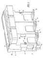
- the trip unit 2 includes a molded housing 4 having a base 6, a cover 8 and a top portion 10. A pair of screws 12 secures the cover 8 to the base 6. Disposed from the base 6 are three-phase line end terminals 14,16,18. The cover 8 includes corresponding load end terminals 20,22,24, respectively.
- the base 6 includes a surface 26 (as shown in Figure 2), which is disposed adjacent to a circuit breaker frame 28 as shown in Figure 21.
- the trip unit 2 is advantageously adapted for engagement within and disengagement from the circuit breaker frame 28.
- the base surface 26 includes an opening 30 for a plunger, such as a rotary plunger 32 (as best shown in Figure 15), and an opening 34 for an attachment button 36 (as best shown in Figure 3).
- the rotary plunger 32 is pivotally mounted with respect to the housing 4 and includes a first or on position (Figure 18), a second or tripped position ( Figure 20) and a third or reset position ( Figures 1 and 19A-19B).
- the on position is substantially flush with the base surface 26, the tripped position is extended from the surface 26, and the reset position is pivoted within the opening 30 and recessed behind the surface 26.
- the cover 8 includes an opening 38 for receiving an earth leakage button 40 (as best shown in Figure 10).
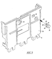
- the attachment button 36 is biased away from the surface 26 of the base 6 by a spring 42.
- the attachment button 36 includes a pair of legs 44 and a plunger 46 (shown in Figure 5).
- the legs 44 have opposing feet 48, which extend in opposite directions (up and down with respect to Figure 3), and which protrude through and are captured by openings 50 in the base 6 of Figure 5.
- the attachment button plunger 46 protrudes through an opening 52 of the base 6.
- the spring 42 is disposed between the button legs 44 and engages a surface (not shown) of the base 6 between the openings 50.
- Figure 4 shows the assembly of a spring bias mechanism 54 and the rotary plunger 32 (as best shown in Figure 15) at the opening 30 of the base 6.
- the rotary plunger 32 includes a pair of pivot posts 56, which pivotally mount the rotary plunger at a corresponding pair of pivot recesses 58 proximate the opening 30 in the housing base 6.
- the spring mechanism 54 includes two bar members 60,62 and two springs 64,66.
- the first bar member 60 pivotally engages the rotary plunger 32 at an opening 68, the position of which is offset from the pivot posts 56 of the rotary plunger.
- the second bar member 62 engages a pivot recess 69 in the housing base 6 at a position offset from the pivot recesses 58 and at the opposite end of the opening 30.
- the two springs 64,66 suitably engage the opposite ends of the two bar members 60,62.
- the ends of the springs 64,66 have loops 70, which are captured by recesses 72 in the corresponding ends of the bar members 60,62.
- the springs 64,66 thus, bias the rotary plunger 32, in order that the two bar members 60,62 are in about the same plane, which is parallel to the base surface 26 of Figure 3, when the rotary plunger is in the extended or tripped position of Figure 20.
- two springs 64,66 are shown, the invention is applicable to spring mechanisms employing one (not shown) or more springs, which suitably bias a rotary plunger.
- FIG. 5 the assembly from Figure 4 of the base 6, the spring mechanism 54 and the rotary plunger 32 is shown, with the rotary plunger being held in the on position of Figure 18 by a trip bar 76 (as best shown in Figure 16) as will be explained below.
- the trip bar 76 is shown exploded for ease of illustration, although it will be appreciated that the trip bar holds the rotary plunger 32 in its on position.
- a trip bar pivot member 78 passes through a longitudinal opening 80 in the trip bar 76.
- a trip bar spring 82 rests in an opening 84 of the housing base 6.
- a first end 85 of the pivot member 78 rests in a first pivot point 86, and an opposite second end 87 of the member 78 rests in a second pivot point 88 of the base 6.
- the pivot member 78 preferably includes a portion 90 with a shoulder 91, which engages a portion 92 of the trip bar 76 where the opening 80 narrows. This precludes the member 78 from passing all the way through the longitudinal opening 80 (toward the top right of Figure 5).
- the trip bar 76 is, thus, pivotally mounted with respect to and within the housing 4 and functions, as will be discussed in greater detail below, to latch the rotary plunger 32 in the on position ( Figure 18), to release the rotary plunger 32 from such on position to the tripped position ( Figure 20), and to cooperate with the rotary plunger 32 to re-latch it in the on position after the reset position ( Figures 19A-19B).
- the example trip bar 76 includes: (1) a tab 94 for the plunger 46 of the attachment button 36 of Figures 3 and 5; (2) a tab 96 for a plunger 97 of the earth leakage button 40 of Figure 10; (3) a tab 98 for the bias spring 82; (4) a tab 100 for a rotary trip lever 101 ( Figure 6); and (5) a latch surface 102 for a corresponding latch surface 104 (as best shown in Figure 22) of the rotary plunger 32.
- the button plunger 46 engages the tab 94 on the trip bar 76 and rotates the trip bar clockwise (with respect to Figure 5, as viewed from the bottom left, and Figure 18).
- a ground fault (e . g ., equipment protection) bolt on unit engages the earth leakage button 40 ( Figure 10) and depresses the same into the opening 38 of the cover 8
- the button plunger 97 engages the trip bar tab 96 to also rotate the trip bar 76 in the same clockwise direction (with respect to Figures 5 and 18).
- the spring 82 which rests in the base opening 84, biases the trip bar 76 in the opposite rotational direction (e.g. , counter-clockwise with respect to Figures 5 and 18).
- the spring 82 engages the housing base 6 and the tab 98, in order to bias that tab and, thus, the trip bar 76 with respect to the housing 12, in order that the trip bar latch surface 102 engages the corresponding internal latch surface 104 of the rotary plunger 32 (as best shown in the on position of Figure 18).
- the spring 82 thus, biases the trip bar 76 to a non-actuated or on position, which holds the rotary plunger 32 and, hence, prevents the spring mechanism 54 from rotating the rotary plunger 32 to the tripped position of Figure 20.
- the spring 82 biases the tab 98 and the trip bar 76 to resist rotation caused by the buttons 36,40, and the trip bar latch surface 102 engages the rotary plunger latch surface 104, in order to latch the rotary plunger 32 in the on position ( Figure 18).
- the trip bar 76 is rotated ( e.g. , by one of the buttons 36,40)
- the latch surface 102 moves to the right in Figure 18 and releases the latch surface 104 of the rotary plunger 32. This releases the rotary plunger 32, which is biased by the spring mechanism 54, to the tripped position ( Figure 20).
- the rotary trip lever 101 ( Figure 6) includes a surface 106, which engages the tab 100, in order to rotate the trip bar 76 clockwise (with respect to Figures 5 and 18) and, thus, release the latch surface 102 from the rotary plunger latch surface 104, in order to release the rotary plunger from the on position ( Figure 18) to the tripped position ( Figure 20), as was discussed above.
- Figure 6 shows the assembly from Figure 5 of the base 6, the spring mechanism 54, the rotary plunger 32, the trip bar 76 and the trip bar pivot member 78.
- the rotary trip lever 101 (as best shown in Figure 17) and a trip lever pivot member 108 are exploded from the base 6 for ease of illustration.
- the pivot member 108 passes through an opening 110 in the trip lever 101.
- a first end 111 of the pivot member 108 rests in a first pivot point 112, and an opposite second end 113 of the pivot member 108 rests in a second pivot point 114 of the base 6, thereby pivotally mounting the rotary trip lever 101 with respect to the housing base 6 on an axis, which is normal to the pivot axis of the trip bar 76.
- the rotary trip lever 101 includes three operating surfaces 116, 106 and 118.
- the first surface 116 is for engagement by a plunger 120 of a trip actuator, such as a flux shunt trip actuator 122 ( Figure 8) or solenoid, which causes the rotary trip lever 101 to rotate counter-clockwise (as viewed from the bottom right of Figure 6).
- a trip actuator such as a flux shunt trip actuator 122 ( Figure 8) or solenoid
- the trip lever 101 is preferably made of a molded material.
- the third surface 118 is disposed on the end of an elastic arm 121, which extends from the body 123 of the trip lever 101.
- the rotary trip lever 101 rotates in a clockwise direction (as viewed from the bottom right of Figure 6). This causes the first surface 116 of the trip lever 101 to engage the trip actuator plunger 120, in order to reset the trip actuator 122 in a manner to be described, below.
- the elastic arm 121 of the rotary trip lever 101 advantageously flexes (upward with respect to Figure 6), after the trip actuator plunger 120 has been fully reset and, thus, resists further rotation of the rotary trip lever 101 by applying a force to its surface 116.
- the elastic arm 121 advantageously accommodates any overtravel of the rotary plunger 32 beyond its reset position, which might be caused, for example, by manufacturing or other tolerances in the circuit breaker frame 28 of Figure 21.
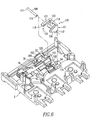
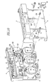
- the assembly from Figure 6 includes the base 6, the spring mechanism 54, the rotary plunger 32, the trip bar 76, the trip bar pivot member 78, the rotary trip lever 101 and the trip lever pivot member 108.
- a trip circuit 126 including two printed circuit boards (PCBs) 128,130, which are interconnected by suitable electrical connectors (not shown).
- the first PCB 128 includes a trip actuator connector 132 disposed on one side 134.
- the opposite side 136 includes a pair of LED indicators 138 (only one is shown), a plurality of manual controls 140 (e.g ., potentiometers; rotary selectors; switches), and an interface connector 142 to a serial communication bus (not shown).
- the second PCB 130 includes three connectors 144,146,148 for receiving signals from three corresponding current transformers (CTs) 150,152,154 (Figure 9).
- CTs current transformers
- the sides 155,157 of the base 6 include slots 156,158 to receive the sides of the first PCB 128, which preferably includes a rectangular cut-out portion 159 (as partially shown in Figure 10) to accommodate the rotary plunger 32 and the portion of the trip bar 76 at the latching surface 102 ( Figure 5).
- the invention is applicable to a wide range of analog and/or digital and/or processor-based trip circuits, such as an electronic trip circuit, which is known to those skilled in the art. Examples of electronic trip circuits are disclosed in U.S. Patent Nos. 5,428,495; and 6,167,329, which are incorporated by reference herein.
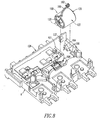
- Figure 8 shows the assembly from Figure 7 including the base 6, the trip circuit 126, the rotary trip lever 101, and the trip lever pivot member 108, with the trip actuator 122 being exploded from the base for ease of illustration.
- the trip actuator 122 includes a set of wires 160 terminated by a connector 162, which mates with the connector 132 of the PCB 128 of the trip circuit 126 as shown in Figure 9.
- the trip actuator 122 rests in a recess 164 in the base 6, which provides a pair of V-shaped supports 166 (only one support 166 is shown) for the opposite ends of the trip actuator.
- the linear plunger 120 When the trip actuator 122 is energized by the trip circuit 126 through the connectors 132,162 and the wires 160, the linear plunger 120 is in an actuated or extended state (shown in phantom line drawing).
- the extended linear plunger 120 engages the trip lever surface 116 ( Figure 17) and rotates the rotary trip lever 101 counter-clockwise (with respect to the bottom right of Figure 8).
- the trip lever surface 106 engages the trip bar tab 100, which rotates the trip bar 76 and disengages the trip bar latch surface 102 from the rotary plunger latch surface 104, in order to release the rotary plunger 32 from the on position ( Figure 18) and trip open the operating mechanism 167 of the attached circuit breaker frame 28 of Figure 21.
- the plunger 120 and the rotary trip lever 101 thus, cooperate to engage and pivot the trip bar 76.
- the trip unit 2 includes a latching mechanism 168, which is formed from the combination of the trip bar 76 and the spring 82 of Figure 5, and a trip actuator mechanism 170, which is formed from the trip actuator 122 having the plunger 120 and a trip member, such as the rotary trip lever 101.
- the latching mechanism 168 functions to latch the rotary plunger 32 of Figure 5 in the on position ( Figure 18) in which a rotary plunger surface 172 ( Figures 2 and 22) is about flush with the surface 26 of the trip unit housing 4 ( Figure 2, which shows the reset position of Figures 19A-19B).
- the latching mechanism 168 also functions to releases the rotary plunger 32 from the on position to the tripped position ( Figure 20), and to re-latch the rotary plunger 32 in the on position by employing the reset position ( Figures 19A-19B) thereof.
- the assembly from Figure 8 includes the base 6, the trip circuit 126, the latching mechanism 168 having the trip actuator 122, two current transformer assemblies 174,176, and a third current transformer assembly 178, which is exploded from the base for ease of illustration.
- the current transformer assemblies 174,176,178 include the current transformers 150,152,154, respectively. These assemblies also include, as shown with the assembly 178, a load side L-shaped conductor 180, a line side conductor 182 having a terminal 184 for a load end conductor 185 of the circuit breaker frame 28 of Figure 21.
- the current transformer 154 of the assembly 178 has an opening (not shown) through which a copper cylindrical center conductor 186 passes.
- the ends of the center conductor 186 are electrically connected ( e.g. , through a peening operation) with the load side conductor 180 and the line side conductor 182.
- Disposed from the current transformer 154 are a set of wires 188 and a connector 190 therefor.
- the connector 190 mates with the corresponding connector 148 of the PCB 130 of the trip circuit 126.
- Each of the CTs 150,152 of the respective CT assemblies 174,176 is disposed about a corresponding one of the conductors 186 and includes a corresponding set of the wires 188.
- the CT assembly 174 includes a connector 194, which defines an output and which is connected to the connector 144 of the PCB 130 of the trip circuit 126.
- the CT assembly 176 includes a connector 195, which defines an output and which is connected to the connector 146 of the PCB 130 of the trip circuit 126.
- the connectors 144,146,148 of the trip circuit 126 define three inputs, which are electrically connected to the outputs of the CTs 150,152,154, respectively.
- the trip circuit connector 132 defines an output having a trip signal 202, which is output through the connector 162 and the wires 160 to the trip actuator 122.
- the PCB 130 receives three input signals 196,198,200 from the three CTs 150,152,154, respectively, and the PCB 128 outputs a control or trip signal 202 through the connectors 132,162 and the wires 160 to the trip actuator 122.
- Figure 10 shows the assembly from Figure 9 including the base 6, the trip circuit 126, the latching mechanism 168 having the trip actuator 122, the CT assemblies 174,176,178 and the cover 8 having the earth leakage button 40 and a spring 204 therefor.
- the cover includes four posts 206,208 and 210,212, which correspond to the four pivot points 86,88 (as best shown in Figure 5) and 112,114 (as best shown in Figure 6), respectively, of the base 6. These posts and pivot points cooperate to pivotally capture the ends of the pivot members 78,108.
- the PCB 130 includes an opening 214 for the pivot point 86 and a cutout 216 for the pivot point 88.
- the plunger 97 engages the tab 96 of the trip bar 76 ( Figure 5), in order to rotate such trip bar and release the rotary plunger 32 ( Figure 5) to the tripped position ( Figure 20), in the manner as was discussed above.
- the spring 204 which rests between an internal surface (not shown) of the cover 8 and a surface 218 of the button 40, biases the button plunger 97 away from the trip bar tab 76.
- the button 40 includes two opposing feet 220 of two legs 221 (only one foot 220 and one leg 221 are shown in Figure 10). The feet 220 extend in opposite directions (left and right with respect to Figure 10) and protrude through and are captured by the cover opening 38.
- the trip unit 2 of Figures 1 and 2 integrates the flux shunt trip actuator 122, the rotary trip lever 101, the trip bar 76 ( Figure 5), the electronic trip circuit 126 and the current transformer assemblies 174,176,178 into the molded case trip unit housing 4 for the molded case circuit breaker 179 of Figure 21. It is believed that the number and complexity of parts is less than in known prior art trip units.
- the mechanical trip bar 76 interfaces directly with the rotary trip lever 101 and rotary plunger 32, thereby providing a very compact tripping system that provides a reliable and repeatable tripping force through such rotary plunger.
- the miniaturized combination of the flux shunt trip actuator 122, the rotary trip lever 101, the trip bar 76 and the rotary plunger 32 in combination with the trip circuit 126 allow the trip unit 2 to be relatively very compact, yet have relatively high reliability and relatively low cost.
- the trip actuator 122 includes a bobbin assembly 231 having the wires 160 and the connector 162, a disk spacer 232, a disc magnet 233, which is preferably magnetized after the assembly steps of Figures 12-14, a housing 234, a cover 235, a wave washer 236, an upper bushing 237, an armature or plunger 238, a lower bushing 239, an internal retaining ring 240, a spring 241 and a set screw 242.
- the disk spacer 232 is inserted into a recess 244 of the bobbin assembly 231 followed by the non-magnetized magnet 233, which is preferably magnetized after the assembly steps of Figures 12-14, in order to provide a more uniform and consistent magnetic field strength, to provide more predictable tripping without subsequent manufacturing adjustment, and to facilitate the convenient assembly of the non-magnetized magnet 233.
- a suitable magnetizer such as a Model 7500/900 - 6i marketed by Magnetic Instruments of Indianapolis, Indiana, may be employed to magnetize the non-magnetized magnet 233 within the assembly of the final trip actuator 122 (as shown in Figure 8).
- the bobbin assembly 231, the spacer 232, the magnet 233 and the housing 234 form the sub-assembly 246 of Figure 14.
- Figure 13 shows the assembly of the cover 235, the wave washer 236, the upper bushing 237, the armature or plunger 238 and the lower bushing 239. This forms the sub-assembly 248 of Figure 14.
- Figure 14 shows the assembly of the sub-assemblies 246,248 along with the internal retaining ring 240, the spring 241 and the set screw 242.
- the sub-assembly 248 is inserted into the recess 250 of the sub-assembly 246.
- the internal retaining ring 240 is employed to hold the sub-assembly 248 within the sub-assembly recess 250 by engaging the rim 251 of the sub-assembly 246.
- the spring 241 passes through the sub-assembly 248 and extends from the disk spacer 232 ( Figure 12) to the set screw 242, which threadably engages the end 252 ( Figures 13 and 14) of the plunger 238.
- a member, the rotary trip lever 101 (Figure 6), includes a first or on position corresponding to the on position ( Figure 18) of the rotary plunger 32, a second or tripped position ( Figure 20), and a third or reset position ( Figures 19A-19B), which resets the trip actuator 122.
- the surface 106 In the first position, the surface 106 is offset from the trip bar tab 100.
- the plunger 120 engages the surface 116 and the surface 106 engages the tab 100, in order to rotate the trip bar 76.
- the rotary plunger surface 125 engages the surface 118 and the surface 116 engages the plunger 120, in order to reset the trip actuator 122.
- a member, such as the linear plunger 120 of Figure 8 includes a first or non-actuated position ( Figure 8) corresponding to the on position ( Figure 18) of the rotary plunger 32, a second or actuated position (as shown in phantom line drawing in Figure 8), and a third or reset position (between the actuated and non-actuated positions), which resets the trip actuator 122 as the armature 238 is attracted by the magnet 233.
- the plunger actuated position engages the surface 116 and rotates the rotary trip lever 101 in response to the output control or trip signal 202 of the trip circuit 126, in order to engage the trip bar 76 with the surface 106 ( Figure 6) and release the rotary plunger 32 from the on position ( Figure 18).
- the rotary plunger surface 125 engages the trip lever surface 118 ( Figure 6) at about the reset position of the rotary plunger 32 and rotates the rotary trip lever 101, in order to engage the trip lever surface 116 with the trip actuator plunger 120 and move that member to the reset position thereof.
- the rotary trip lever elastic arm 121 flexes after the trip actuator plunger 120 reaches or passes the reset position thereof, in order to accommodate any overtravel of the rotary plunger 32 beyond its reset position ( Figures 19A-19B).
- the external surface 172 of the rotary plunger 32 is pivoted outside of the housing 4 ( Figure 2) through the opening 30 thereof in the tripped position ( Figure 20).
- the surface 172 is adapted to engage a latch mechanism 253 of the circuit breaker frame 28 of Figure 21.
- the portion 74 is generally pie-slice shaped, with a first sub-portion 254 having a first radius and a second sub-portion 256 having a smaller second radius.
- the smaller second sub-portion 256 is adapted to provide clearance from other components of the circuit breaker frame 28.
- the trip unit housing opening 30 may include debris (not shown) from such circuit breaker frame. Then, when the rotary plunger portion 74 is pivoted outside of the trip unit housing 4, the rotary plunger 32 advantageously sweeps the debris out of the opening 30.
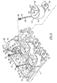
- Figure 18 (latched or on position), Figures 19A-19B (reset or overtravel position) and Figure 20 (tripped position), show the three operating positions of the rotary plunger 32 with respect to the trip actuator 122, the rotary trip lever 101 (as shown in Figure 19B), the trip bar 76 and the spring mechanism 54.
- the trip bar latch surface 102 engages and holds the rotary plunger latch surface 104, in order to latch the rotary plunger 32 in the on position thereof.
- This on position in which the rotary plunger surface 172 is preferably flush with, about flush with or substantially flush to the housing surface 26 ( Figure 2), is intermediate the external tripped position of Figure 20 and the internal reset position of Figures 19A-19B.
- the rotary plunger 32 trips the circuit breaker 179 of Figure 21 by rotating the latch 332 (clockwise with respect to Figure 21) as the rotary plunger 32 rotates (clockwise with respect to Figures 18 and 20) from the latched position of Figure 18 to the tripped position of Figure 20.
- this rotation releases the trip bar latch surface 102 from the rotary plunger latch surface 104.
- the rotary plunger 32 rotates outward as shown in Figure 20, with its surface 172 being pivoted external to the housing 4 of Figure 2, in order to trip open the circuit breaker 179.
- the rotary plunger 32 includes a cam surface 258, which engages a surface 260 (extending downward in Figure 5) near the latching surface 102 of the trip bar 76 ( Figure 5).
- the trip bar tab 262 which forms the surfaces 102,260, engages the rotary plunger cam surface 258.
- the cam surface 258 releases the tab 262 and the trip bar 76 rotates (counterclockwise with respect to the bottom left of Figure 5) under the bias of the spring 82.
- the trip bar latching surface 102 rotates toward the left of Figures 18 and 20 in preparation to engage the rotary plunger latching surface 104 in the on position of Figure 18.
- the trip bar latch surface 102 re-engages the rotary plunger latch surface 104 as the rotary plunger 32 rotates from the external tripped position ( Figure 20) to the internal reset position ( Figures 19A-19B) thereof.
- the rotary plunger surface 125 rotates the trip lever 101 (as shown in Figure 19B), in order to reset the trip actuator 122 through its plunger 120 ( Figure 8). Any overtravel of the rotary plunger 32 flexes the rotary trip lever elastic arm 121.
- the trip actuator 122 After a trip, the trip actuator 122 is no longer energized; however, the trip actuator spring 241 ( Figures 11 and 14) causes the solenoid armature or plunger 238 to remain extended, thereby preventing the trip bar 76 from returning to the latched or on position ( Figure 18) under the bias of its spring 82 ( Figure 5).
- the rotary plunger 32 rotates the rotary trip lever 101, through its resilient arm 121, in order to cause the trip actuator 122 to be reset to the position where the armature or plunger 238 is held in place by the magnet 233 thereof.
- the trip bar spring 82 causes the trip bar 76 to rotate (counterclockwise with respect to Figures 19A-19B) back to its latching position (Figure 18), in order to hold the rotary plunger 32 in the latched or on position of Figure 18.
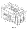
- Figure 21 shows the molded case circuit breaker 179 including the circuit breaker frame 28 and the removable trip unit 2 of Figure 1.
- Examples of circuit breakers and circuit breaker frames are disclosed in U.S. Patent Nos. 5,910,760; 6,137,386; and 6,144,271, which are incorporated by reference herein.
- the example breaker or interrupter 179 includes a main base 300 and primary cover 302 attached to a secondary cover 304.
- the base 300 and covers 302,304 form a housing 305.
- a handle 306 extends through a secondary escutcheon 308 in the secondary cover 304 and an aligned primary escutcheon 310 in the primary cover 302.
- the operating mechanism 167 is interconnected with the handle 306 and assists in opening and closing separable main contacts 312 as is well known.
- the circuit breaker 179 has a line end 314 including a plurality of line terminals 315,316,317, a load end 316 including a plurality of load terminals 318,319,320, a right side accessory region or pocket 322 and a left side accessory pocket or region 324.
- the separable contacts 312 are electrically connected between the line terminals 315,316,317 and a plurality of load end terminals 325,326,327.
- the load end terminals 325,326,327 of the circuit breaker frame 28 are electrically connected to the line end terminals 14,16,18 (as best shown in Figures 1 and 2) of the trip unit 2 by a plurality of conductors 328,329,330, respectively.
- the corresponding load end terminals 20,22,24 ( Figure 1) of the trip unit 2 are electrically connected the corresponding line end terminals 14,16,18, respectively, by the conductors 186 ( Figure 9).
- Those load end terminals 20,22,24 are also electrically connected by suitable user installed terminations (not shown) to the load terminals 318,319,320, respectively, of the circuit breaker frame 28.
- the latch mechanism 253 latches the operating mechanism 167 to provide the closed position of the separable contacts 312 and releases such operating mechanism to provide the open position of such separable contacts.
- the latch mechanism 253 includes a primary frame latch (not shown), which operates or rotates on a primary frame latch pivot (not shown).
- the primary frame latch cooperates with the secondary frame latch 332, which rotates on a secondary frame latch pivot 334.
- Actuation of the latch mechanism 253 occurs exclusively by way of the utilization of the resetable trip unit rotary plunger 32 ( Figures 4, 15 and 22), which is normally contained entirely within the removable trip unit 2.
- the pivotable secondary frame latch 332 is in disposition to be pivoted by the rotary plunger surface 172 through the rotation of rotary plunger 32.
- the rotary plunger design provides more travel in order to reliably trip open the circuit breaker frame 28. After being tripped, when the trip unit 2 is removed from the circuit breaker frame 28, the frame surface 336 engages the rotary plunger 32 and rotates it toward the on position, thereby permitting removal of the trip unit 2 from the frame 28.
- the user may push in and latch the rotary plunger 32 in the on position thereof prior to insertion of the trip unit 2 in the circuit breaker frame 28.
- the rotary plunger 32 may have two levels 254,256 ( Figure 22) in order to provide clearances with the circuit breaker frame components.
- the rotary plunger 32 sweeps debris by rotating and, thus, by providing a sweeping action.
Landscapes
- Engineering & Computer Science (AREA)
- Power Engineering (AREA)
- Breakers (AREA)
- Refuge Islands, Traffic Blockers, Or Guard Fence (AREA)
Applications Claiming Priority (2)
| Application Number | Priority Date | Filing Date | Title |
|---|---|---|---|
| US10/633,007 US6921873B2 (en) | 2003-08-01 | 2003-08-01 | Circuit breaker trip unit employing a rotary plunger |
| US633007 | 2003-08-01 |
Publications (2)
| Publication Number | Publication Date |
|---|---|
| EP1503396A2 true EP1503396A2 (fr) | 2005-02-02 |
| EP1503396A3 EP1503396A3 (fr) | 2007-05-16 |
Family
ID=33541553
Family Applications (1)
| Application Number | Title | Priority Date | Filing Date |
|---|---|---|---|
| EP04018232A Withdrawn EP1503396A3 (fr) | 2003-08-01 | 2004-08-02 | Déclencheur de disjoncteur, avec plongeur rotatif |
Country Status (7)
| Country | Link |
|---|---|
| US (1) | US6921873B2 (fr) |
| EP (1) | EP1503396A3 (fr) |
| CN (1) | CN100492577C (fr) |
| AU (1) | AU2004203223B2 (fr) |
| BR (1) | BRPI0403103A (fr) |
| CA (1) | CA2475699A1 (fr) |
| ZA (1) | ZA200406083B (fr) |
Cited By (3)
| Publication number | Priority date | Publication date | Assignee | Title |
|---|---|---|---|---|
| EP1978540A2 (fr) | 2007-04-05 | 2008-10-08 | Eaton Corporation | Appareil de commutation électrique et ensemble d'actionneur de déclenchement correspondant |
| EP2816582A1 (fr) | 2013-06-20 | 2014-12-24 | Schneider Electric Industries SAS | Déclencheur et procédé de fabrication d'un tel déclencheur |
| WO2015088665A1 (fr) * | 2013-12-12 | 2015-06-18 | Eaton Corporation | Interface d'actionneur à déclencheur de dérivation de flux et mécanisme de réinitialisation de disjoncteur pour disjoncteur |
Families Citing this family (9)
| Publication number | Priority date | Publication date | Assignee | Title |
|---|---|---|---|---|
| US7358836B2 (en) * | 2006-03-29 | 2008-04-15 | Eaton Corporation | Shield, and printed circuit board and electrical apparatus employing the same |
| US7515025B2 (en) * | 2006-12-20 | 2009-04-07 | General Electric Company | Current trip unit for circuit breaker |
| US7518476B2 (en) | 2007-04-05 | 2009-04-14 | Eaton Corporation | Electrical switching apparatus and trip actuator reset assembly therefor |
| US7570139B2 (en) | 2007-04-05 | 2009-08-04 | Eaton Corporation | Electrical switching apparatus, and trip actuator assembly and reset assembly therefor |
| US7586394B2 (en) | 2007-07-10 | 2009-09-08 | Eaton Corporation | Electrical switching apparatus, and trip actuator reset assembly and lever arm assembly therefor |
| US8476992B2 (en) | 2011-10-07 | 2013-07-02 | Siemens Industry, Inc. | Circuit breaker having an unlocking mechanism and methods of operating same |
| DE102014201501A1 (de) * | 2014-01-28 | 2015-07-30 | Siemens Aktiengesellschaft | Externe Ansteuerung eines elektromagnetischen Auslösers |
| US9728348B2 (en) * | 2015-12-21 | 2017-08-08 | Eaton Corporation | Electrical switching apparatus with electronic trip unit |
| CN113192796A (zh) * | 2020-12-08 | 2021-07-30 | 国网浙江省电力有限公司 | 一种塑壳断路器馈电模块及使用该模块的柜体 |
Citations (1)
| Publication number | Priority date | Publication date | Assignee | Title |
|---|---|---|---|---|
| FR2506066A1 (fr) * | 1981-05-18 | 1982-11-19 | Merlin Gerin | Mecanisme de manoeuvre d'un disjoncteur electrique multipolaire a basse tension |
Family Cites Families (14)
| Publication number | Priority date | Publication date | Assignee | Title |
|---|---|---|---|---|
| FR1190781A (fr) * | 1958-01-23 | 1959-10-15 | Bresson Faille Marchand Ets | Relais mécanique sensible utilisable notamment comme déclencheur |
| JPS58131622A (ja) * | 1982-01-29 | 1983-08-05 | 三菱電機株式会社 | 気中しや断器 |
| US4642430A (en) * | 1985-07-18 | 1987-02-10 | Westinghouse Electric Corp. | Molded case circuit breaker with an improved contoured cradle |
| US4603313A (en) * | 1985-08-30 | 1986-07-29 | Westinghouse Electric Corp. | Circuit breaker with replaceable rating plug interlock and push to trip button |
| FR2589626B1 (fr) * | 1985-10-31 | 1989-03-03 | Merlin Gerin | Mecanisme de commande d'un disjoncteur equipe d'un systeme accumulateur d'energie |
| US5117210A (en) * | 1991-02-11 | 1992-05-26 | General Electric Company | Molded case circuit breaker field-installable accessories |
| US5428495A (en) * | 1992-09-30 | 1995-06-27 | Eaton Corporation | Electrical switching apparatus with digital trip unit and automatic frequency selection |
| US5910760A (en) * | 1997-05-28 | 1999-06-08 | Eaton Corporation | Circuit breaker with double rate spring |
| US6167329A (en) * | 1998-04-06 | 2000-12-26 | Eaton Corporation | Dual microprocessor electronic trip unit for a circuit interrupter |
| US6437261B1 (en) * | 1998-12-07 | 2002-08-20 | General Electric Company | Interlock for use in an electric motor handle and contactor combination |
| US6144271A (en) * | 1999-08-18 | 2000-11-07 | Eaton Corporation | Circuit breaker with easily installed removable trip unit |
| US6137386A (en) * | 1999-08-18 | 2000-10-24 | Eaton Corporation | Circuit breaker with trip unit mounted tripping plunger and latch therefore |
| US6225883B1 (en) * | 2000-02-15 | 2001-05-01 | Eaton Corporation | Circuit breaker with latch and toggle mechanism operating in perpendicular planes |
| US6448522B1 (en) * | 2001-01-30 | 2002-09-10 | General Electric Company | Compact high speed motor operator for a circuit breaker |
-
2003
- 2003-08-01 US US10/633,007 patent/US6921873B2/en not_active Expired - Lifetime
-
2004
- 2004-07-16 AU AU2004203223A patent/AU2004203223B2/en not_active Ceased
- 2004-07-23 CA CA002475699A patent/CA2475699A1/fr not_active Abandoned
- 2004-07-26 BR BR0403103-2A patent/BRPI0403103A/pt not_active IP Right Cessation
- 2004-07-29 ZA ZA2004/06083A patent/ZA200406083B/en unknown
- 2004-07-30 CN CNB2004100702640A patent/CN100492577C/zh not_active Expired - Fee Related
- 2004-08-02 EP EP04018232A patent/EP1503396A3/fr not_active Withdrawn
Patent Citations (1)
| Publication number | Priority date | Publication date | Assignee | Title |
|---|---|---|---|---|
| FR2506066A1 (fr) * | 1981-05-18 | 1982-11-19 | Merlin Gerin | Mecanisme de manoeuvre d'un disjoncteur electrique multipolaire a basse tension |
Cited By (6)
| Publication number | Priority date | Publication date | Assignee | Title |
|---|---|---|---|---|
| EP1978540A2 (fr) | 2007-04-05 | 2008-10-08 | Eaton Corporation | Appareil de commutation électrique et ensemble d'actionneur de déclenchement correspondant |
| EP1978540A3 (fr) * | 2007-04-05 | 2010-05-19 | Eaton Corporation | Appareil de commutation électrique et ensemble d'actionneur de déclenchement correspondant |
| EP2816582A1 (fr) | 2013-06-20 | 2014-12-24 | Schneider Electric Industries SAS | Déclencheur et procédé de fabrication d'un tel déclencheur |
| RU2662733C2 (ru) * | 2013-06-20 | 2018-07-30 | Шнейдер Электрик Эндюстри Сас | Выключатель и способ изготовления такого выключателя |
| WO2015088665A1 (fr) * | 2013-12-12 | 2015-06-18 | Eaton Corporation | Interface d'actionneur à déclencheur de dérivation de flux et mécanisme de réinitialisation de disjoncteur pour disjoncteur |
| US9466451B2 (en) | 2013-12-12 | 2016-10-11 | Eaton Corporation | Flux shunt trip actuator interface and breaker reset mechanism for circuit breaker |
Also Published As
| Publication number | Publication date |
|---|---|
| AU2004203223B2 (en) | 2008-09-25 |
| US6921873B2 (en) | 2005-07-26 |
| CN1581397A (zh) | 2005-02-16 |
| CN100492577C (zh) | 2009-05-27 |
| ZA200406083B (en) | 2005-08-31 |
| EP1503396A3 (fr) | 2007-05-16 |
| AU2004203223A1 (en) | 2005-02-17 |
| CA2475699A1 (fr) | 2005-02-01 |
| BRPI0403103A (pt) | 2005-04-05 |
| US20050023120A1 (en) | 2005-02-03 |
Similar Documents
| Publication | Publication Date | Title |
|---|---|---|
| US6853279B1 (en) | Circuit breaker trip unit including a plunger resetting a trip actuator mechanism and a trip bar | |
| US5552755A (en) | Circuit breaker with auxiliary switch actuated by cascaded actuating members | |
| US6215378B1 (en) | Circuit breaker with dual function test button remote from test circuit | |
| JP2894052B2 (ja) | 回路遮断器 | |
| US6903289B2 (en) | Circuit breaker employing an illuminated operating handle | |
| US6850135B1 (en) | Circuit breaker trip unit employing a reset overtravel compensating rotary trip lever | |
| US6921873B2 (en) | Circuit breaker trip unit employing a rotary plunger | |
| US5907461A (en) | Molded case circuit breaker with ground fault protection and signaling switches | |
| US20100073113A1 (en) | Electromagnet Assembly Directly Driving Latch Of An Electronic Circuit Breaker | |
| CA2292470C (fr) | Mecanisme d'actionnement de multiples microcontacts | |
| US4987395A (en) | Circuit breaker alarm-switch operating apparatus | |
| EP1978540B1 (fr) | Appareil de commutation électrique et ensemble d'actionneur de déclenchement correspondant | |
| US7161104B2 (en) | Trip-free PCB mountable relay configuration and method | |
| US7064635B2 (en) | Circuit breaker including alarm interface lever | |
| CA2437111C (fr) | Disjoncteur | |
| US6831534B2 (en) | External actuator interlock mechanism for circuit breaker | |
| CA2628291A1 (fr) | Appareillage de commutation electrique et dispositif connexe de remise du declencheur a l'etat initial | |
| EP1978538A2 (fr) | Appareil de commutation électrique et ensemble de remise à zéro d'actionneur de déclenchement correspondant | |
| US6700082B1 (en) | Trip actuator for a circuit breaker | |
| US6917267B2 (en) | Non-conductive barrier for separating a circuit breaker trip spring and cradle | |
| EP1643527B1 (fr) | Mécanisme de commande pour un interrupteur auxiliaire et disjoncteur incorporant celui-ci | |
| CN110931321A (zh) | 一种小型断路器的中性极结构 | |
| CA2425346C (fr) | Disjoncteur avec derivation pour reacheminer un courant transitoire eleve, et procede associe | |
| US20060158813A1 (en) | Electronic type protective relay | |
| US7106155B2 (en) | Double-lever mechanism, trip actuator assembly and electrical switching apparatus employing the same |
Legal Events
| Date | Code | Title | Description |
|---|---|---|---|
| PUAI | Public reference made under article 153(3) epc to a published international application that has entered the european phase |
Free format text: ORIGINAL CODE: 0009012 |
|
| AK | Designated contracting states |
Kind code of ref document: A2 Designated state(s): AT BE BG CH CY CZ DE DK EE ES FI FR GB GR HU IE IT LI LU MC NL PL PT RO SE SI SK TR |
|
| AX | Request for extension of the european patent |
Extension state: AL HR LT LV MK |
|
| PUAL | Search report despatched |
Free format text: ORIGINAL CODE: 0009013 |
|
| AK | Designated contracting states |
Kind code of ref document: A3 Designated state(s): AT BE BG CH CY CZ DE DK EE ES FI FR GB GR HU IE IT LI LU MC NL PL PT RO SE SI SK TR |
|
| AX | Request for extension of the european patent |
Extension state: AL HR LT LV MK |
|
| 17P | Request for examination filed |
Effective date: 20070823 |
|
| AKX | Designation fees paid |
Designated state(s): AT BE BG CH CY CZ DE DK EE ES FI FR GB GR HU IE IT LI LU MC NL PL PT RO SE SI SK TR |
|
| 17Q | First examination report despatched |
Effective date: 20100609 |
|
| STAA | Information on the status of an ep patent application or granted ep patent |
Free format text: STATUS: THE APPLICATION IS DEEMED TO BE WITHDRAWN |
|
| 18D | Application deemed to be withdrawn |
Effective date: 20101020 |