EP1503063A1 - EGR control apparatus for diesel engine - Google Patents
EGR control apparatus for diesel engine Download PDFInfo
- Publication number
- EP1503063A1 EP1503063A1 EP04018149A EP04018149A EP1503063A1 EP 1503063 A1 EP1503063 A1 EP 1503063A1 EP 04018149 A EP04018149 A EP 04018149A EP 04018149 A EP04018149 A EP 04018149A EP 1503063 A1 EP1503063 A1 EP 1503063A1
- Authority
- EP
- European Patent Office
- Prior art keywords
- egr
- injection quantity
- opening degree
- accelerator opening
- smoothening
- Prior art date
- Legal status (The legal status is an assumption and is not a legal conclusion. Google has not performed a legal analysis and makes no representation as to the accuracy of the status listed.)
- Granted
Links
- 238000002347 injection Methods 0.000 claims abstract description 90
- 239000007924 injection Substances 0.000 claims abstract description 90
- 239000000446 fuel Substances 0.000 claims abstract description 60
- 230000007423 decrease Effects 0.000 claims abstract description 15
- 238000000034 method Methods 0.000 claims abstract description 10
- 238000011144 upstream manufacturing Methods 0.000 claims description 5
- 230000003247 decreasing effect Effects 0.000 claims description 3
- 230000001133 acceleration Effects 0.000 abstract description 16
- 238000010586 diagram Methods 0.000 description 9
- 239000000779 smoke Substances 0.000 description 9
- 239000007789 gas Substances 0.000 description 5
- 238000002485 combustion reaction Methods 0.000 description 4
- 230000000994 depressogenic effect Effects 0.000 description 4
- IJGRMHOSHXDMSA-UHFFFAOYSA-N Atomic nitrogen Chemical compound N#N IJGRMHOSHXDMSA-UHFFFAOYSA-N 0.000 description 2
- 230000007812 deficiency Effects 0.000 description 2
- 230000006866 deterioration Effects 0.000 description 1
- 230000000694 effects Effects 0.000 description 1
- 239000000203 mixture Substances 0.000 description 1
- 230000004048 modification Effects 0.000 description 1
- 238000012986 modification Methods 0.000 description 1
- 229910052757 nitrogen Inorganic materials 0.000 description 1
- 230000035939 shock Effects 0.000 description 1
- 239000002699 waste material Substances 0.000 description 1
- XLYOFNOQVPJJNP-UHFFFAOYSA-N water Substances O XLYOFNOQVPJJNP-UHFFFAOYSA-N 0.000 description 1
Images



Classifications
-
- F—MECHANICAL ENGINEERING; LIGHTING; HEATING; WEAPONS; BLASTING
- F02—COMBUSTION ENGINES; HOT-GAS OR COMBUSTION-PRODUCT ENGINE PLANTS
- F02D—CONTROLLING COMBUSTION ENGINES
- F02D41/00—Electrical control of supply of combustible mixture or its constituents
- F02D41/0025—Controlling engines characterised by use of non-liquid fuels, pluralities of fuels, or non-fuel substances added to the combustible mixtures
- F02D41/0047—Controlling exhaust gas recirculation [EGR]
- F02D41/005—Controlling exhaust gas recirculation [EGR] according to engine operating conditions
-
- F—MECHANICAL ENGINEERING; LIGHTING; HEATING; WEAPONS; BLASTING
- F02—COMBUSTION ENGINES; HOT-GAS OR COMBUSTION-PRODUCT ENGINE PLANTS
- F02M—SUPPLYING COMBUSTION ENGINES IN GENERAL WITH COMBUSTIBLE MIXTURES OR CONSTITUENTS THEREOF
- F02M26/00—Engine-pertinent apparatus for adding exhaust gases to combustion-air, main fuel or fuel-air mixture, e.g. by exhaust gas recirculation [EGR] systems
- F02M26/02—EGR systems specially adapted for supercharged engines
-
- F—MECHANICAL ENGINEERING; LIGHTING; HEATING; WEAPONS; BLASTING
- F02—COMBUSTION ENGINES; HOT-GAS OR COMBUSTION-PRODUCT ENGINE PLANTS
- F02M—SUPPLYING COMBUSTION ENGINES IN GENERAL WITH COMBUSTIBLE MIXTURES OR CONSTITUENTS THEREOF
- F02M26/00—Engine-pertinent apparatus for adding exhaust gases to combustion-air, main fuel or fuel-air mixture, e.g. by exhaust gas recirculation [EGR] systems
- F02M26/13—Arrangement or layout of EGR passages, e.g. in relation to specific engine parts or for incorporation of accessories
- F02M26/22—Arrangement or layout of EGR passages, e.g. in relation to specific engine parts or for incorporation of accessories with coolers in the recirculation passage
-
- F—MECHANICAL ENGINEERING; LIGHTING; HEATING; WEAPONS; BLASTING
- F02—COMBUSTION ENGINES; HOT-GAS OR COMBUSTION-PRODUCT ENGINE PLANTS
- F02M—SUPPLYING COMBUSTION ENGINES IN GENERAL WITH COMBUSTIBLE MIXTURES OR CONSTITUENTS THEREOF
- F02M26/00—Engine-pertinent apparatus for adding exhaust gases to combustion-air, main fuel or fuel-air mixture, e.g. by exhaust gas recirculation [EGR] systems
- F02M26/49—Detecting, diagnosing or indicating an abnormal function of the EGR system
-
- F—MECHANICAL ENGINEERING; LIGHTING; HEATING; WEAPONS; BLASTING
- F02—COMBUSTION ENGINES; HOT-GAS OR COMBUSTION-PRODUCT ENGINE PLANTS
- F02D—CONTROLLING COMBUSTION ENGINES
- F02D11/00—Arrangements for, or adaptations to, non-automatic engine control initiation means, e.g. operator initiated
- F02D11/06—Arrangements for, or adaptations to, non-automatic engine control initiation means, e.g. operator initiated characterised by non-mechanical control linkages, e.g. fluid control linkages or by control linkages with power drive or assistance
- F02D11/10—Arrangements for, or adaptations to, non-automatic engine control initiation means, e.g. operator initiated characterised by non-mechanical control linkages, e.g. fluid control linkages or by control linkages with power drive or assistance of the electric type
- F02D11/105—Arrangements for, or adaptations to, non-automatic engine control initiation means, e.g. operator initiated characterised by non-mechanical control linkages, e.g. fluid control linkages or by control linkages with power drive or assistance of the electric type characterised by the function converting demand to actuation, e.g. a map indicating relations between an accelerator pedal position and throttle valve opening or target engine torque
-
- F—MECHANICAL ENGINEERING; LIGHTING; HEATING; WEAPONS; BLASTING
- F02—COMBUSTION ENGINES; HOT-GAS OR COMBUSTION-PRODUCT ENGINE PLANTS
- F02D—CONTROLLING COMBUSTION ENGINES
- F02D41/00—Electrical control of supply of combustible mixture or its constituents
- F02D41/02—Circuit arrangements for generating control signals
- F02D41/14—Introducing closed-loop corrections
- F02D41/1401—Introducing closed-loop corrections characterised by the control or regulation method
- F02D2041/1413—Controller structures or design
- F02D2041/1432—Controller structures or design the system including a filter, e.g. a low pass or high pass filter
-
- F—MECHANICAL ENGINEERING; LIGHTING; HEATING; WEAPONS; BLASTING
- F02—COMBUSTION ENGINES; HOT-GAS OR COMBUSTION-PRODUCT ENGINE PLANTS
- F02D—CONTROLLING COMBUSTION ENGINES
- F02D41/00—Electrical control of supply of combustible mixture or its constituents
- F02D41/02—Circuit arrangements for generating control signals
- F02D41/04—Introducing corrections for particular operating conditions
- F02D41/10—Introducing corrections for particular operating conditions for acceleration
-
- F—MECHANICAL ENGINEERING; LIGHTING; HEATING; WEAPONS; BLASTING
- F02—COMBUSTION ENGINES; HOT-GAS OR COMBUSTION-PRODUCT ENGINE PLANTS
- F02M—SUPPLYING COMBUSTION ENGINES IN GENERAL WITH COMBUSTIBLE MIXTURES OR CONSTITUENTS THEREOF
- F02M26/00—Engine-pertinent apparatus for adding exhaust gases to combustion-air, main fuel or fuel-air mixture, e.g. by exhaust gas recirculation [EGR] systems
- F02M26/02—EGR systems specially adapted for supercharged engines
- F02M26/04—EGR systems specially adapted for supercharged engines with a single turbocharger
- F02M26/05—High pressure loops, i.e. wherein recirculated exhaust gas is taken out from the exhaust system upstream of the turbine and reintroduced into the intake system downstream of the compressor
-
- Y—GENERAL TAGGING OF NEW TECHNOLOGICAL DEVELOPMENTS; GENERAL TAGGING OF CROSS-SECTIONAL TECHNOLOGIES SPANNING OVER SEVERAL SECTIONS OF THE IPC; TECHNICAL SUBJECTS COVERED BY FORMER USPC CROSS-REFERENCE ART COLLECTIONS [XRACs] AND DIGESTS
- Y02—TECHNOLOGIES OR APPLICATIONS FOR MITIGATION OR ADAPTATION AGAINST CLIMATE CHANGE
- Y02T—CLIMATE CHANGE MITIGATION TECHNOLOGIES RELATED TO TRANSPORTATION
- Y02T10/00—Road transport of goods or passengers
- Y02T10/10—Internal combustion engine [ICE] based vehicles
- Y02T10/40—Engine management systems
Definitions
- This invention relates to an EGR (Exhaust Gas Recirculation) control apparatus, and in particular, an EGR control apparatus for a diesel engine which can conduct a decrease control for an EGR volume in at least high load region of the engine operating state when the engine accelerates, in order to avoid a smoke aggravation and a poor acceleration.
- EGR exhaust Gas Recirculation
- EGR is a technology in which a part of exhaust gas is recirculated from an engine exhaust pipe to an engine combustion chamber to lower combustion temperature for reducing NOx (oxides of nitrogen) to be generated (see Japanese Patent Application published with No. 09-324673, for example).
- EGR is stopped to secure a volume of fresh intake air supplied to a cylinder.
- the stop of EGR is performed when a target fuel injection quantity exceeds a predetermined threshold value in at least the high load region of the engine operating state (i.e., EGR stop region).
- the target fuel injection quantity is calculated based on an accelerator opening degree and an engine rotating speed, etc.
- the target fuel injection quantity equals to an actual fuel injection quantity to be injected from an injector, it is also used as a parameter for judging the stop of EGR.
- a detected value by the accelerator opening sensor is processed by a smoothening-process in order to ease an impact when acceleration, and then the target fuel injection quantity is determined based on the accelerator opening degree after smoothening-processed.
- the target fuel injection quantity after smoothening-processed as such exceeds a predetermined threshold value in at least the high load region of the engine operating state (i.e., EGR stop region)
- EGR is stopped, and simultaneously, a corresponding quantity of fuel to the target fuel injection quantity is injected from the injector.
- the injector can adapt to a pilot injection or a multi injection, the quantity of the fuel injected from the injector can be rapidly increased in response to an increase of the target fuel injection quantity after smoothening-processed as described above.
- the stop of EGR since it is carried out by closing an EGR valve provided in an EGR passage which communicates the engine exhaust pipe with the engine intake pipe, a certain amount of time lag is unavoidable which is caused by a mechanical time lag and an airflow lag.
- actuators for the injector and the EGR valve are respectively inputted with the increase signals of the target injection quantity after smoothening-processed, and the increase control for the fuel injection quantity and the closing control for the EGR valve is conducted based on these signals.
- the injector is quick to respond the increase of the target fuel injection quantity after smoothening-processed, and can promptly inject the actual, increased quantity of fuel corresponding to the target fuel injection quantity.
- this increase of the fuel injection quantity precedes the stop of EGR, because a mechanical actuation lag, the airflow lag, and the lag caused by the smoothening-process simultaneously occur in the EGR valve actuator side.
- EGR stop lag time the intake air volume tends to be insufficient relative to the fuel injection quantity, and the smoke aggravation and/or the poor acceleration may occur.
- an EGR control apparatus for a diesel engine concerning a first invention comprises: EGR means to adjust EGR volume which is recirculated from an exhaust pipe to an intake pipe; filter means to carry out a smoothening-process to an accelerator opening degree detected by an accelerator opening degree sensor; injection quantity determination means to determine a target fuel injection quantity to be injected from an injector, using the accelerator opening degree after smoothening-processed; and control means to calculate a fuel injection quantity for judging EGR stop, using the accelerator opening degree before smoothening-processed, to allow the EGR means to carry out a decrease control for the EGR volume when the fuel injection quantity for judging EGR stop exceeds a predetermined threshold value.
- An EGR control apparatus for a diesel engine concerning a second invention comprises: EGR means to adjust EGR volume which is recirculated from an exhaust pipe to an intake pipe; calculation means to calculate a provisional fuel injection quantity, using an accelerator opening degree detected by an accelerator opening degree sensor; filter means to carry out a smoothening-process to the provisional fuel injection quantity calculated by the calculation means; fuel injection quantity determination means to control a fuel injection quantity to be injected from an injector, using the fuel injection quantity after smoothening-processed; and control means to allow the EGR means to carry out a decrease control for the EGR volume when the provisional fuel injection quantity before smoothening-processed exceeds a predetermined threshold value:
- the EGR means may have an EGR passage which communicates the exhaust pipe and the intake pipe with each other, and an EGR valve which is provided in the EGR passage and adjusts the EGR volume by changing its passage area.
- the EGR means may have an EGR passage which communicates the exhaust pipe and the intake pipe with each other, and an intake throttle valve which is provided in the intake pipe at upstream side of a position connected with the EGR passage and adjusts the EGR volume by changing a passage area of the intake pipe.
- Fig. 1 is a system diagram depicting an EGR control apparatus for a diesel engine concerning a first embodiment of this invention.
- Fig. 2 is a diagram depicting an operation of the EGR control apparatus.
- Fig. 3 (a) is a diagram depicting change of an actual accelerator opening degree Pp.
- Fig. 3 (b) is a diagram depicting change of an accelerator opening degree for judging EGR Ppn.
- Fig. 3 (c) is a diagram depicting change of an injection quantity for judging EGR stop.
- Fig. 3 (d) is a diagram depicting change of an opening degree of the EGR valve.
- Fig. 4 is a diagram depicting an EGR stop region.
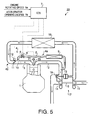
- Fig. 5 is a diagram depicting a diesel engine provided with the above-mentioned EGR control apparatus.
- Fig. 6 is a system diagram depicting an EGR control apparatus according to another embodiment.
- Fig. 5 depicts a diesel engine 1 provided with an EGR control apparatus 22 concerning this embodiment.
- the diesel engine 1 is provided with EGR means 4 to adjust a volume of EGR gas recirculated from an exhaust pipe 2 to an intake pipe 3.
- the EGR means 4 constitutes a part of the EGR control apparatus 22, and consists of first EGR means 4a and second EGR means 4b.
- the 1st EGR means 4a has an EGR passage 5 which communicates an exhaust pipe 2 and an intake pipe 3 with each other, and an EGR valve 6 which is provided in the EGR passage 5 and changes a passage area of the EGR passage 5.
- An opening degree of the EGR valve 6 is adjusted by an actuator 8 connected to an ECU (Electronic Control Unit) 7. EGR volume will increase if the EGR valve 6 is controlled to open, while the EGR volume will decrease if the EGR valve 6 is controlled to close.
- An EGR cooler 9 is provided in the EGR passage 5.
- the 2nd EGR means 4b has the above-mentioned EGR passage 5, and an intake throttle valve 11 which is provided in the intake pipe 3 at upstream side of a position 10 connected with the EGR passage 5 and changes a passage area of the intake pipe 3.
- An opening degree of the intake throttle valve 11 is adjusted by an actuator 12 connected to the ECU 7. EGR volume will decrease if the intake throttle valve 11 is controlled to open, while the EGR volume will increase if the intake throttle valve 11 is controlled to close.
- a turbine 14 is provided in the exhaust pipe 2 at downstream side of a position 13 connected with the EGR passage 5, and a compressor 15 is provided in the intake pipe 3 at upstream side of the intake throttle valve 11.
- the compressor 15 and the turbine 14 are coupled to each other by a rotating shaft 16 to constitute a turbocharger 17.
- An inter cooler 18 is provided in the intake pipe 3 at downstream side of the compressor 15, and a waste gate 19 is provided in the exhaust pipe 2 at upstream side of the turbine 14.
- An injector 20 is provided in a cylinder head to inject fuel into a cylinder.
- An actuator 21 is provided in the injector 20 to control a fuel injection quantity and a fuel injection timing.
- a fuel injection system such as a common rail type or other conventional type is adopted as the actuator 21.
- the actuator 21 is connected to the ECU 7.
- Data representing an operating state of the engine such as an engine rotating speed (rpm) or an accelerator opening degree (or others such as a water temperature or an oil temperature), is inputted into the ECU 7.
- the ECU 7 transmits operation signals to the actuator 12 of the intake throttle valve11, the actuator 8 of the EGR valve 6, and the actuator 21 of the injector 20 respectively, based on the inputted data.
- the ECU 7 constitutes the EGR control apparatus 22 concerning this embodiment.
- Programs to perform an EGR control as shown in Fig. 1 is inputted into the ECU 7.
- filter means 23 is inputted into ECU 7 as a program.
- the filter means 23 carries out a smoothening-process (e.g., a primary delay process) to an accelerator opening degree signal Pp detected by an accelerator opening degree sensor, and outputs an accelerator opening degree signal Ppn after smoothening-processed.
- a smoothening-process e.g., a primary delay process
- Injection quantity determination means 24 is also inputted into the ECU 7 as a program.
- the injection quantity determination means 24 calculates a target fuel injection quantity Qo to be injected from the injector 20, using the accelerator opening degree after smoothening-processed Ppn.
- This means 24 has a map M1 to output the above-mentioned injection quantity Qo based on at least the signal of the accelerator opening degree after smoothening-processed Ppn, and the signal of the engine rotating speed Ne.
- Control means 25 is further inputted into the ECU 7 as a program.
- the control means 25 calculates a fuel injection quantity for judging EGR stop Qcut, using the signal of the accelerator opening degree before smoothening-processed Pp, and allows the first and/or second EGR means 4a and/or 4b to carry out a decrease control for the EGR volume when the fuel injection quantity for judging EGR stop Qcut exceeds a predetermined threshold value Hi.
- the control means 25 has a map M2 to output the above-mentioned injection quantity Qcut based on at least the signal of the accelerator opening degree before smoothening-processed Pp and the signal of the engine rotating speed Ne.
- control means 25 has an adding machine 26 to add a judging hysteresis value Qhys to the above-mentioned lower limit threshold value Qbor.
- the sum of these values (Qbor + Qhys) constitutes the above-mentioned threshold value Hi.
- the opening degrees of the EGR valve 6 and/or the intake throttle valve 11 are controlled such that the normal volume of the EGR gas is supplied to the engine.
- This normal EGR volume is such a volume that can suppress the combustion temperature and NOx, and can prevent deterioration of combustion and smoke, and is determined according to the map not shown, based on the engine rotating speed signal Ne and the accelerator opening degree signal Pp, etc.
- the EGR stop signal is outputted only when an engine operating state is in an EGR stop region x set as a high load and high speed region (at least a high load region), as shown in Fig. 4. It is because the smoke aggravation and the poor acceleration will occur unless the EGR is stopped in this EGR stop region x.
- the accelerator When the accelerator is rapidly depressed and the engine operating state shifts to the high load region (the EGR stop region of Fig. 4) at the time of acceleration, the quantity of fuel injected from the injector 20 is increased and the EGR is stopped.
- the increase of the injection quantity and the EGR stop are performed as follows.
- the accelerator opening degree signal Pp outputted from the accelerator opening degree sensor is smoothening-processed by the filter means 23, and the accelerator opening degree after smoothening-processed Ppn which increases more gently than the actual accelerator opening degree is outputted.
- the accelerator opening degree after smoothening-processed Ppn is inputted into the map M1 to calculate the target injection quantity Qo. Therefore, the injector 20 will inject the quantity Qo of fuel which is eased relative to an increase of the actual accelerator opening degree. Thereby, stepwise shock during acceleration is restrained.
- the accelerator opening degree before smoothening-processed Pp is inputted into the map M2 to calculate the injection quantity for judging EGR stop Qcut according to the increase of the actual accelerator opening degree not smoothening-processed.
- the injection quantity Qcut exceeds the threshold value Hi, the EGR valve 6 is fully closed and/or the intake throttle valve 11 is fully opened to stop the EGR.
- the accelerator opening degree signal after smoothening-processed Ppn is used for determining the injection quantity Qo to be injected from the injector 20, while the accelerator opening degree signal before smoothening-processed Pp is used for determining the injection quantity Qcut used as a criterion for judging the EGR stop.
- the EGR can be stopped in advance of (or approximately at the same time as) the increase of the fuel injection quantity from the injector 20. Therefore, sufficient amount of fresh intake air for the injection quantity which increases at the time of acceleration can be secured, and the smoke aggravation and the poor acceleration can be restrained.
- Fig. 3 (a) shows the actual accelerator opening degree (Pp)
- a solid line of Fig. 3 (b) shows the accelerator opening degree for judging EGR concerning this embodiment (i.e., the accelerator opening degree signal Pp before smoothening-processed)
- a broken line of Fig. 3 (b) shows the accelerator opening degree for judging EGR concerning a compared example (a conventional example) (i.e., the accelerator opening degree signal Pp after smoothening-processed).
- a smoothening-processed signal relative to the actual accelerator opening degree i.e., the accelerator opening degree used for determining the injection quantity from the injector 20
- the accelerator opening degree for judging EGR has been used as the accelerator opening degree for judging EGR.
- the actual accelerator opening degree before smoothening-processed (Pp) itself is used as the accelerator opening degree for judging EGR (Pp).
- the injection quantity for judging EGR cut (Qcut) concerning this embodiment increases more quickly than the injection quantity for judging EGR cut of the conventional example, because the injection quantity Qcut concerning this embodiment is not smoothening-processed. Therefore, as shown in Fig. 3 (d), the EGR valve 6 of this embodiment is closed more quickly than that of the conventional example (and/or, the intake throttle valve 11 of this embodiment is opened more quickly than that of the conventional example).
- the injection quantity after smoothening-processed shown by the broken line in Fig. 3(c) is used as the injection quantity Qo from the injector 20. Therefore, even if the time lag caused by the operation lag of the each valves 6, 11 and the airflow lag is taken into consideration, the fuel injection quantity from the injector 20 increases after (or approximately at the same time as) the EGR is stopped by the EGR valve 6 being closed (and/or the intake throttle valve 11 being opened).
- Fig. 2 This operation is shown in Fig. 2.
- the signal after smoothening-processed is used in the conventional example, while the signal before smoothening-processed is used in this embodiment. Therefore, the signal in this embodiment exceeds the threshold value Hi sooner than the signal in the conventional example. Therefore, the EGR valve 6 (and/or the intake throttle valve 11) in this embodiment can be closed (and/or opened) sooner than the EGR valve (and/or the intake throttle valve) in the conventional example by the lead time.
- the injection quantity from the injector 20 increases after (or approximately at the same time as) the EGR is stopped, even if the time lag caused by the operation lag of the EGR valve 6 (and/or the intake throttle valve 11) and the airflow lag is taken into consideration. Therefore, when the injection quantity from the injector 20 is increased, a sufficient volume of intake air can be secured, and the smoke aggravation and the poor acceleration are avoidable.
- a provisional fuel injection quantity Qimg is calculated by using a map M4 of the calculation means 28, based on at least the accelerator opening degree before smoothening-processed Pp outputted from the accelerator sensor, and the engine rotating speed Ne outputted from the engine rotating speed sensor.
- the injection quantity Qimg is smoothening-processed by the filter means 29, and then the target injection quantity Qo is determined by the injection quantity determination means 30 which uses the injection quantity after smoothening-processed.
- the provisional injection quantity Qimg before smoothening-processed exceeds the predetermined threshold value Hi, the EGR valve 6 is controlled to close (and/or, the intake throttle valve 11 is controlled to open) by the control means 31.
- the target injection quantity after smoothening-processed Qo is used not only for a control of the fuel injection quantity from the injector 20, but also for a various type of control logic with a requirement to avoid the impact when acceleration. Moreover, it is not always necessary to fully close the EGR valve 6, and it is not always necessary to fully open the intake throttle valve 11. That is, an EGR volume may be merely decreased from the current volume, instead of making it zero. Furthermore, in the map M3 for determining the lower limit threshold value Qbor, a relation of the value Qbor to the engine rotation speed Ne may be linear or constant.
- the EGR control apparatus for the diesel engine since it can carry out the decrease control of the EGR in advance of (or approximately at the same time as) increase of the fuel injection quantity when acceleration, the smoke aggravation and the poor acceleration caused by deficiency of the intake air volume can be prevented.
Landscapes
- Engineering & Computer Science (AREA)
- Chemical & Material Sciences (AREA)
- Combustion & Propulsion (AREA)
- Mechanical Engineering (AREA)
- General Engineering & Computer Science (AREA)
- Output Control And Ontrol Of Special Type Engine (AREA)
- Exhaust-Gas Circulating Devices (AREA)
- Electrical Control Of Air Or Fuel Supplied To Internal-Combustion Engine (AREA)
- Combined Controls Of Internal Combustion Engines (AREA)
- Control Of Throttle Valves Provided In The Intake System Or In The Exhaust System (AREA)
Abstract
Description
Claims (10)
- An EGR control apparatus for a diesel engine comprising:EGR means to adjust an EGR volume which is recirculated from an exhaust pipe to an intake pipe;filter means to carry out a smoothening-process to an accelerator opening degree detected by an accelerator opening degree sensor;injection quantity determination means to determine a target fuel injection quantity to be injected from an injector, using the accelerator opening degree after smoothening-processed; andcontrol means to calculate a fuel injection quantity for judging EGR stop, using the accelerator opening degree before smoothening-processed, to allow the EGR means to carry out a decrease control for the EGR volume when the fuel injection quantity for judging EGR stop exceeds a predetermined threshold value.
- An EGR control apparatus for a diesel engine comprising:EGR means to adjust an EGR volume which is recirculated from an exhaust pipe to an intake pipe;calculation means to calculate a provisional fuel injection quantity, using an accelerator opening degree detected by an accelerator opening degree sensor;filter means to carry out a smoothening-process to the provisional fuel injection quantity calculated by the calculation means;fuel injection quantity determination means to control a fuel injection quantity to be injected from an injector, using the fuel injection quantity after smoothening-processed; andcontrol means to allow the EGR means to carry out a decrease control for the EGR volume when the provisional fuel injection quantity before smoothening-processed exceeds a predetermined threshold value.
- The EGR control apparatus as defined in claim 1 or 2, characterized in that the EGR means has an EGR passage which communicates the exhaust pipe and the intake pipe with each other, and an EGR valve which is provided in the EGR passage and changes a passage area of the EGR passage to adjust the EGR volume.
- The EGR control apparatus as defined in claim 3, characterized in that the EGR means has an intake throttle valve which is provided in the intake pipe at upstream side of a position connected with the EGR passage and changes a passage area of the intake pipe to adjust the EGR volume.
- The EGR control apparatus as defined in any one of claims 1 to 4, characterized in that the threshold value is calculated by adding a predetermined judging hysteresis to an EGR stop lower limit value determined based on an engine rotation speed.
- The EGR control apparatus as defined in claim 5, characterized in that the control means prohibits the EGR means to carry out the decrease control when the fuel injection quantity for judging EGR stop becomes less than the EGR stop lower limit threshold value.
- The EGR control apparatus as defined in any one of claims 1 to 6, characterized in that the control means allows the EGR means to carry out the decrease control when an engine operating state is at least in a high load region.
- The EGR control apparatus as defined in claim 1, characterized in that the fuel injection quantity for judging EGR stop is determined based on at least the accelerator opening degree before smoothening-processed by the filter means, and an engine rotating speed.
- An EGR control apparatus comprising:characterized in that the ECU carries out a smoothening-process to a signal obtained from the accelerator opening degree sensor, determines the signal for driving the injector based on the signal smoothening-processed, and utilize the signal obtained from the accelerator opening degree sensor not smoothening-processed to determine the signal for driving the EGR means based on the signal before smoothening-processed.an accelerator opening degree sensor to detect an accelerator opening degree;EGR means to adjust an EGR volume which is recirculated from an exhaust pipe to an intake pipe of an engine;an injector to inject fuel into a cylinder of the engine; andan ECU to determine a signal for driving the injector and a signal for driving the EGR means;
- The EGR control apparatus as defined in claim 9, characterized in that the ECU determines a signal for decreasing the EGR volume as the signal for driving the EGR means in at least a high load region of the engine operating state.
Applications Claiming Priority (2)
| Application Number | Priority Date | Filing Date | Title |
|---|---|---|---|
| JP2003203702A JP4417664B2 (en) | 2003-07-30 | 2003-07-30 | EGR control device for diesel engine |
| JP2003203702 | 2003-07-30 |
Publications (2)
| Publication Number | Publication Date |
|---|---|
| EP1503063A1 true EP1503063A1 (en) | 2005-02-02 |
| EP1503063B1 EP1503063B1 (en) | 2015-09-16 |
Family
ID=33535606
Family Applications (1)
| Application Number | Title | Priority Date | Filing Date |
|---|---|---|---|
| EP04018149.7A Expired - Lifetime EP1503063B1 (en) | 2003-07-30 | 2004-07-30 | EGR control apparatus for diesel engine |
Country Status (3)
| Country | Link |
|---|---|
| US (1) | US6966303B2 (en) |
| EP (1) | EP1503063B1 (en) |
| JP (1) | JP4417664B2 (en) |
Families Citing this family (9)
| Publication number | Priority date | Publication date | Assignee | Title |
|---|---|---|---|---|
| DE102006039300A1 (en) * | 2006-08-22 | 2008-02-28 | Knorr-Bremse Systeme für Nutzfahrzeuge GmbH | Device and method for supplying fresh air to a turbocharged reciprocating internal combustion engine |
| US7389771B2 (en) * | 2006-08-30 | 2008-06-24 | Cummins, Inc. | Closed loop EGR control method and system using water content measurement |
| JP4735519B2 (en) * | 2006-11-17 | 2011-07-27 | トヨタ自動車株式会社 | Exhaust gas recirculation device for internal combustion engine |
| JP4743169B2 (en) * | 2007-06-13 | 2011-08-10 | トヨタ自動車株式会社 | Internal combustion engine control apparatus and method |
| JP5511989B2 (en) * | 2011-01-07 | 2014-06-04 | 本田技研工業株式会社 | Control device for internal combustion engine |
| JP5870524B2 (en) * | 2011-07-13 | 2016-03-01 | いすゞ自動車株式会社 | Engine control device |
| US20130160429A1 (en) * | 2011-09-28 | 2013-06-27 | International Engine Intellectual Property Company, Llc | Limiting nox emissions |
| JP6262685B2 (en) * | 2015-04-23 | 2018-01-17 | トヨタ自動車株式会社 | Vehicle control apparatus equipped with continuously variable transmission |
| US11073100B2 (en) * | 2018-11-16 | 2021-07-27 | Fca Us Llc | Cylinder based low pressure cooled exhaust gas recirculation transient measurement methodology |
Citations (7)
| Publication number | Priority date | Publication date | Assignee | Title |
|---|---|---|---|---|
| JPS55128649A (en) * | 1979-03-29 | 1980-10-04 | Toyota Motor Corp | Exhaust gas recirculation device for diesel engine |
| JPS5786535A (en) * | 1980-11-15 | 1982-05-29 | Mazda Motor Corp | Fuel injector for diesel engine |
| JPS6394036A (en) * | 1986-10-08 | 1988-04-25 | Toyota Motor Corp | Exhaust recirculation control device for diesel-engine |
| US4976239A (en) * | 1984-02-07 | 1990-12-11 | Nissan Motor Company, Limited | Throttle control system with noise-free accelerator position input |
| JP2001342877A (en) * | 2000-05-30 | 2001-12-14 | Mazda Motor Corp | Control unit for diesel engine |
| EP1234970A2 (en) * | 2001-02-22 | 2002-08-28 | Toyota Jidosha Kabushiki Kaisha | Fuel supply amount controller for internal combustion engine |
| JP2002256915A (en) * | 2001-02-28 | 2002-09-11 | Hino Motors Ltd | Method and apparatus for controlling EGR valve |
Family Cites Families (9)
| Publication number | Priority date | Publication date | Assignee | Title |
|---|---|---|---|---|
| US5002031A (en) * | 1989-05-17 | 1991-03-26 | Mitsubishi Denki Kabushiki Kaisha | Fuel control apparatus for an internal-combustion engine |
| JP3067583B2 (en) * | 1995-04-27 | 2000-07-17 | トヨタ自動車株式会社 | Diesel engine control unit |
| JPH08303278A (en) | 1995-05-02 | 1996-11-19 | Nissan Motor Co Ltd | Fuel injection control device for diesel engine |
| JP3355872B2 (en) | 1995-06-13 | 2002-12-09 | 三菱自動車工業株式会社 | Engine excess air ratio detection device and exhaust gas recirculation control device |
| JPH09324673A (en) | 1996-06-07 | 1997-12-16 | Toyota Motor Corp | Intake control device for diesel engine |
| JPH10339215A (en) * | 1997-06-09 | 1998-12-22 | Nissan Motor Co Ltd | Engine EGR control device |
| JP3971004B2 (en) * | 1997-12-19 | 2007-09-05 | 株式会社日立製作所 | Combustion switching control device for internal combustion engine |
| JP4006834B2 (en) * | 1998-07-07 | 2007-11-14 | 日産自動車株式会社 | EGR valve control device for diesel engine |
| JP2000205055A (en) | 1999-01-13 | 2000-07-25 | Mazda Motor Corp | Control device for engine with turbocharger |
-
2003
- 2003-07-30 JP JP2003203702A patent/JP4417664B2/en not_active Expired - Fee Related
-
2004
- 2004-07-27 US US10/899,900 patent/US6966303B2/en not_active Expired - Lifetime
- 2004-07-30 EP EP04018149.7A patent/EP1503063B1/en not_active Expired - Lifetime
Patent Citations (7)
| Publication number | Priority date | Publication date | Assignee | Title |
|---|---|---|---|---|
| JPS55128649A (en) * | 1979-03-29 | 1980-10-04 | Toyota Motor Corp | Exhaust gas recirculation device for diesel engine |
| JPS5786535A (en) * | 1980-11-15 | 1982-05-29 | Mazda Motor Corp | Fuel injector for diesel engine |
| US4976239A (en) * | 1984-02-07 | 1990-12-11 | Nissan Motor Company, Limited | Throttle control system with noise-free accelerator position input |
| JPS6394036A (en) * | 1986-10-08 | 1988-04-25 | Toyota Motor Corp | Exhaust recirculation control device for diesel-engine |
| JP2001342877A (en) * | 2000-05-30 | 2001-12-14 | Mazda Motor Corp | Control unit for diesel engine |
| EP1234970A2 (en) * | 2001-02-22 | 2002-08-28 | Toyota Jidosha Kabushiki Kaisha | Fuel supply amount controller for internal combustion engine |
| JP2002256915A (en) * | 2001-02-28 | 2002-09-11 | Hino Motors Ltd | Method and apparatus for controlling EGR valve |
Non-Patent Citations (6)
| Title |
|---|
| PATENT ABSTRACTS OF JAPAN vol. 0041, no. 79 (M - 046) 11 December 1980 (1980-12-11) * |
| PATENT ABSTRACTS OF JAPAN vol. 0061, no. 78 (M - 155) 11 September 1982 (1982-09-11) * |
| PATENT ABSTRACTS OF JAPAN vol. 0123, no. 32 (M - 738) 8 September 1988 (1988-09-08) * |
| PATENT ABSTRACTS OF JAPAN vol. 1997, no. 03 31 March 1997 (1997-03-31) * |
| PATENT ABSTRACTS OF JAPAN vol. 2002, no. 04 4 August 2002 (2002-08-04) * |
| PATENT ABSTRACTS OF JAPAN vol. 2003, no. 01 14 January 2003 (2003-01-14) * |
Also Published As
| Publication number | Publication date |
|---|---|
| JP4417664B2 (en) | 2010-02-17 |
| US6966303B2 (en) | 2005-11-22 |
| US20050022792A1 (en) | 2005-02-03 |
| JP2005048611A (en) | 2005-02-24 |
| EP1503063B1 (en) | 2015-09-16 |
Similar Documents
| Publication | Publication Date | Title |
|---|---|---|
| JP4301295B2 (en) | EGR system for internal combustion engine | |
| JP4534514B2 (en) | Diesel engine control device | |
| US6868329B2 (en) | Control method of EGR system of engine | |
| US6363922B1 (en) | Exhaust gas recirculation pressure differential sensor error compensation | |
| JP4859875B2 (en) | Diesel engine exhaust gas recirculation control system | |
| EP1316702B1 (en) | EGR Control Apparatus for Internal Combustion Engine | |
| US20080058994A1 (en) | Abnormality determination apparatus and method for blow-by gas feedback device, and engine control unit | |
| JP2007291974A (en) | Exhaust gas recirculation device for internal combustion engine | |
| KR101951613B1 (en) | Exhaust recirculation control method and exhaust recirculation control device | |
| US9464585B2 (en) | Exhaust gas recirculation control system of engine | |
| JP6041753B2 (en) | Engine exhaust gas recirculation system | |
| WO2009110419A1 (en) | Engine | |
| US9470142B2 (en) | Control apparatus for supercharged internal combustion engine | |
| US7066144B2 (en) | Control device and method for internal combustion engine | |
| WO2012047191A1 (en) | Engine controlling emissions during transient operations | |
| US6966303B2 (en) | EGR control apparatus for diesel engine | |
| KR102021711B1 (en) | Control device of internal combustion engine and control method of internal combustion engine | |
| US10711689B2 (en) | Control device of internal combustion engine | |
| EP1550800A2 (en) | Method of controlling an internal combustion engine | |
| JPH04334750A (en) | Exhaust circulation device of diesel engine with supercharger | |
| US9926839B2 (en) | Internal combustion engine and method for controlling internal combustion engine | |
| JP6107876B2 (en) | Control device for turbocharged engine | |
| WO2010022833A1 (en) | A method for controlling the egr and throttle valves in an internal combustion engine | |
| JP4000923B2 (en) | Inlet throttle valve control device for turbocharged diesel engine for vehicle | |
| JP4419855B2 (en) | Combustion switching control system for compression ignition internal combustion engine |
Legal Events
| Date | Code | Title | Description |
|---|---|---|---|
| PUAI | Public reference made under article 153(3) epc to a published international application that has entered the european phase |
Free format text: ORIGINAL CODE: 0009012 |
|
| AK | Designated contracting states |
Kind code of ref document: A1 Designated state(s): AT BE BG CH CY CZ DE DK EE ES FI FR GB GR HU IE IT LI LU MC NL PL PT RO SE SI SK TR |
|
| AX | Request for extension of the european patent |
Extension state: AL HR LT LV MK |
|
| AKX | Designation fees paid |
Designated state(s): DE FR GB IT |
|
| 17P | Request for examination filed |
Effective date: 20050701 |
|
| 17Q | First examination report despatched |
Effective date: 20051110 |
|
| GRAP | Despatch of communication of intention to grant a patent |
Free format text: ORIGINAL CODE: EPIDOSNIGR1 |
|
| INTG | Intention to grant announced |
Effective date: 20150320 |
|
| RIN1 | Information on inventor provided before grant (corrected) |
Inventor name: YOMOGIDA, KOICHIRO Inventor name: TOMIKAWA, KAZUYA Inventor name: ISHII, NOBUTAKA Inventor name: HARUNARI, TOSHIAKI Inventor name: NAKANO, FUTOSHI |
|
| GRAS | Grant fee paid |
Free format text: ORIGINAL CODE: EPIDOSNIGR3 |
|
| GRAA | (expected) grant |
Free format text: ORIGINAL CODE: 0009210 |
|
| AK | Designated contracting states |
Kind code of ref document: B1 Designated state(s): DE FR GB IT |
|
| REG | Reference to a national code |
Ref country code: GB Ref legal event code: FG4D |
|
| REG | Reference to a national code |
Ref country code: DE Ref legal event code: R096 Ref document number: 602004047901 Country of ref document: DE |
|
| PG25 | Lapsed in a contracting state [announced via postgrant information from national office to epo] |
Ref country code: IT Free format text: LAPSE BECAUSE OF FAILURE TO SUBMIT A TRANSLATION OF THE DESCRIPTION OR TO PAY THE FEE WITHIN THE PRESCRIBED TIME-LIMIT Effective date: 20150916 |
|
| REG | Reference to a national code |
Ref country code: DE Ref legal event code: R097 Ref document number: 602004047901 Country of ref document: DE |
|
| PLBE | No opposition filed within time limit |
Free format text: ORIGINAL CODE: 0009261 |
|
| REG | Reference to a national code |
Ref country code: FR Ref legal event code: PLFP Year of fee payment: 13 |
|
| STAA | Information on the status of an ep patent application or granted ep patent |
Free format text: STATUS: NO OPPOSITION FILED WITHIN TIME LIMIT |
|
| 26N | No opposition filed |
Effective date: 20160617 |
|
| PGFP | Annual fee paid to national office [announced via postgrant information from national office to epo] |
Ref country code: FR Payment date: 20160722 Year of fee payment: 13 |
|
| REG | Reference to a national code |
Ref country code: FR Ref legal event code: ST Effective date: 20180330 |
|
| PG25 | Lapsed in a contracting state [announced via postgrant information from national office to epo] |
Ref country code: FR Free format text: LAPSE BECAUSE OF NON-PAYMENT OF DUE FEES Effective date: 20170731 |
|
| PGFP | Annual fee paid to national office [announced via postgrant information from national office to epo] |
Ref country code: GB Payment date: 20220609 Year of fee payment: 19 |
|
| PGFP | Annual fee paid to national office [announced via postgrant information from national office to epo] |
Ref country code: DE Payment date: 20230607 Year of fee payment: 20 |
|
| GBPC | Gb: european patent ceased through non-payment of renewal fee |
Effective date: 20230730 |
|
| PG25 | Lapsed in a contracting state [announced via postgrant information from national office to epo] |
Ref country code: GB Free format text: LAPSE BECAUSE OF NON-PAYMENT OF DUE FEES Effective date: 20230730 |
|
| REG | Reference to a national code |
Ref country code: DE Ref legal event code: R071 Ref document number: 602004047901 Country of ref document: DE |