EP1502877A1 - A dispenser - Google Patents
A dispenser Download PDFInfo
- Publication number
- EP1502877A1 EP1502877A1 EP03017251A EP03017251A EP1502877A1 EP 1502877 A1 EP1502877 A1 EP 1502877A1 EP 03017251 A EP03017251 A EP 03017251A EP 03017251 A EP03017251 A EP 03017251A EP 1502877 A1 EP1502877 A1 EP 1502877A1
- Authority
- EP
- European Patent Office
- Prior art keywords
- dispensing
- dispenser
- orifice
- items
- actuating part
- Prior art date
- Legal status (The legal status is an assumption and is not a legal conclusion. Google has not performed a legal analysis and makes no representation as to the accuracy of the status listed.)
- Withdrawn
Links
Images


Classifications
-
- B—PERFORMING OPERATIONS; TRANSPORTING
- B65—CONVEYING; PACKING; STORING; HANDLING THIN OR FILAMENTARY MATERIAL
- B65D—CONTAINERS FOR STORAGE OR TRANSPORT OF ARTICLES OR MATERIALS, e.g. BAGS, BARRELS, BOTTLES, BOXES, CANS, CARTONS, CRATES, DRUMS, JARS, TANKS, HOPPERS, FORWARDING CONTAINERS; ACCESSORIES, CLOSURES, OR FITTINGS THEREFOR; PACKAGING ELEMENTS; PACKAGES
- B65D83/00—Containers or packages with special means for dispensing contents
- B65D83/04—Containers or packages with special means for dispensing contents for dispensing annular, disc-shaped, spherical or like small articles, e.g. tablets or pills
- B65D83/0409—Containers or packages with special means for dispensing contents for dispensing annular, disc-shaped, spherical or like small articles, e.g. tablets or pills the dispensing means being adapted for delivering one article, or a single dose, upon each actuation
-
- B—PERFORMING OPERATIONS; TRANSPORTING
- B65—CONVEYING; PACKING; STORING; HANDLING THIN OR FILAMENTARY MATERIAL
- B65D—CONTAINERS FOR STORAGE OR TRANSPORT OF ARTICLES OR MATERIALS, e.g. BAGS, BARRELS, BOTTLES, BOXES, CANS, CARTONS, CRATES, DRUMS, JARS, TANKS, HOPPERS, FORWARDING CONTAINERS; ACCESSORIES, CLOSURES, OR FITTINGS THEREFOR; PACKAGING ELEMENTS; PACKAGES
- B65D83/00—Containers or packages with special means for dispensing contents
- B65D83/04—Containers or packages with special means for dispensing contents for dispensing annular, disc-shaped, spherical or like small articles, e.g. tablets or pills
- B65D83/049—Containers or packages with special means for dispensing contents for dispensing annular, disc-shaped, spherical or like small articles, e.g. tablets or pills the dispensing means forming a part of a removable closure, e.g. gripping teeth or cavity
-
- B—PERFORMING OPERATIONS; TRANSPORTING
- B65—CONVEYING; PACKING; STORING; HANDLING THIN OR FILAMENTARY MATERIAL
- B65D—CONTAINERS FOR STORAGE OR TRANSPORT OF ARTICLES OR MATERIALS, e.g. BAGS, BARRELS, BOTTLES, BOXES, CANS, CARTONS, CRATES, DRUMS, JARS, TANKS, HOPPERS, FORWARDING CONTAINERS; ACCESSORIES, CLOSURES, OR FITTINGS THEREFOR; PACKAGING ELEMENTS; PACKAGES
- B65D2583/00—Containers or packages with special means for dispensing contents
- B65D2583/04—For dispensing annular, disc-shaped or spherical or like small articles or tablets
- B65D2583/0472—For dispensing annular, disc-shaped or spherical or like small articles or tablets characterised by the dispensing action
- B65D2583/0477—For dispensing annular, disc-shaped or spherical or like small articles or tablets characterised by the dispensing action the container is maintained in the same position during the dispensing of several successive articles or doses
- B65D2583/0481—One reciprocating action, e.g. to or from
Definitions
- the present invention relates generally to a dispenser for holding a plurality of individual items and allowing them to be dispensed.
- a common form of dispenser of this type is a tablet dispenser for medicaments, sweeteners or the like product.
- Tablet dispensers usually comprise a body for containing a plurality of items to be dispensed, and an actuating means operable by the user to cause an item to be dispensed from the body.
- the actuating means may be, for example, a push-button (EP 0 894 736), a rotatable part (US 6,142,337) or a squeezable shell (WO 00/68109).
- tablets are dispensed directly out of the dispenser.
- medicaments are dispensed directly into the hand of the user, and sweetening tablets are dispensed directly into a beverage.
- tablets may be misdirected and then lost as they are dispensed; if a user's hand is required to catch the tablets as they are dispensed this prohibits two-handed operation of the actuating means, which may be necessary for those without the strength or dexterity to operate the actuating means with a single hand; the items which will be dispensed may be water-soluble and therefore it would be preferable not to dispense them directly onto a user's hand; if items are dispensed directly into a beverage the number of tablets dispensed may be forgotten during the dispensing operation and therefore an accurate dose will not be possible.
- the present invention seeks to address the above problems.
- the present invention provides a dispenser comprising a container body which, in use, contains a plurality of items to be dispensed, a dispensing part having an orifice movable from a non-dispensing position in which items cannot pass through the orifice to a dispensing position in which an item can pass from the container body through the orifice, and an actuating part operable to move the dispensing part to the dispensing position, characterised that, the dispenser is arranged so that, in use, items passing through the orifice are released into the actuating part.
- the present invention therefore uses the actuating part not only to actuate item-release means, but also to catch items as they are dispensed. Once the required number of items has been dispensed the items can be removed from the actuating part.
- the actuating part may be removable completely from the remainder of the dispenser so that the items can be easily removed.
- the dispenser may be adapted to dispense items individually into the actuating part. This allows the required number of items to be accurately dispensed into the actuating part prior to the items leaving the dispenser.
- the dispensing orifice may be defined by one or more dispensing members movable in response to movement of the actuating part.
- the or each dispensing member may be adapted to move radially outwardly or inwardly to move the dispensing part to the dispensing position.
- the number and form of the dispensing member/s can be matched to any particular application. The only essential requirement is that it/they define an orifice adapted to restrict/allow the passage of items when the dispensing part is in the non-dispensing/dispensing position.
- the actuating part may include a projection which, together with the dispensing member/s, defines a restricted dispensing zone adjacent the orifice into which a single item can pass when the dispensing part is moved to the dispensing position. Inclusion of the projection therefore allows items to be dispensed individually into the actuating part.
- the projection may also be adapted to cause the dispensing member/s to move as the actuating part is moved.
- the projection therefore serves a dual function.
- the dispensing part may be biassed towards the non-dispensing position so that following the dispensing of one or more items, the dispensing part automatically returns to the non-dispensing position.
- the dispenser may further comprise a tamperband.
- the tamperband may be situated such that it must be removed before the actuating part can be operated to move the dispensing part. The dispenser cannot be operated before the tamperband is removed.
- dispensing members When a plurality of dispensing members are used and they move radially outwardly to move the dispensing part to the dispensing position, they may define a circular orifice. In the non-dispensing position the orifice defined by the dispensing members is smaller than an item. When the actuating part is operated the dispensing members move radially outwardly and increase the size of the circular orifice.
- the members may define an ovoid orifice in the non-dispensing position.
- the actuating part When the actuating part is operated the dispensing members move radially inwardly and circularise the orifice.
- the items are shaped such that they cannot pass through an ovoid orifice but can pass through a circular orifice which may have the same circumference; for example the items could be disc-shape or spherical.
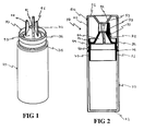
- a dispenser generally indicated (10) comprising a body part (20), a dispensing part (30) and an actuating part (50) [Fig.1 shows just the parts (20, 30) before the part (50) has been added].
- the body part (20) is a cylindrical container for holding items to be dispensed.
- the body part (20) is closed at one end by a disc-shape end plate (21), and the dispensing part (30) is connected to the other end of the body part (20).
- the actuating part (50) is a cap comprising a top plate (51) and a cylindrical skirt (52) which depends from the periphery of the plate (51).
- the top plate (51) includes a central frustoconical depression which forms a frustoconical projection (53) in the interior of the actuating part (50).
- the projection (53) defines an annular channel (55) around its periphery.
- annular bead At the open end of the skirt (52) is an annular bead (54) the purpose of which is described in more detail below.
- the dispensing part (30) comprises a lower connecting portion (31) and an upper dispensing portion (32).
- the connecting portion (31) comprises a lower tubular skirt (33) sized to fit inside the body part (20).
- the outer wall of the connecting portion (31) has a flange (34) approximately half way along its length. The flange (34) acts as a depth stop to limit the amount the connecting portion (31) can be inserted into the body part (20).
- the outer wall of the connecting portion (31) has an annular groove (35) sized and positioned so that when the connecting portion is fully inserted into the body part (20) it aligns with an annular bead (22) on the inner surface of the body part (best shown in Figs. 3a to 3f).
- the bead (22) thereby retains the dispensing part (30) in the body part (20).
- the connecting portion (31) extends with an upper tubular skirt (36).
- the upper tubular skirt (36) includes an annular groove (37) which is trapezoidal in section.
- the groove (37) receives the bead (54) from the inside surface of the cap skirt (52) to clip the actuating part (50) onto the dispensing part (30) in such a way that the actuating part (50) can move axially with respect to the dispensing part (30), with the bead (54) sliding axially in the groove (37).
- the dispensing portion (32) of the dispensing part (30) extends from the upper tubular skirt (36).
- the dispensing portion (32) comprises three identical dispensing members (38).
- Each of the members (38) includes a link portion (39) which extends orthogonally from the upper tubular skirt (36) to connect the member (38) to the skirt (36) in such a way that the member (38) can resiliently flex in the radial direction.
- Each member (38) further comprises a curved plate (40) which is shaped so that together the members (38) form a frustoconical structure with a central circular orifice (41) at its end remote from the link portions (38).
- the orifice (41) is shaped and configured, i.e. adapted, to the items to be dispensed.
- Each of the members (38) further includes a leg (42) which extends from the outer surface of the plate (40).
- annular tamper evident band 60
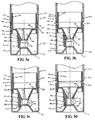
- Figs. 3a to 3f show the upper part of the dispenser in an inverted, as used, state compared to Figs.1 and 2
- Fig.3a shows the dispenser in an unopened and unused configuration.
- the tamper band (60) is connected between the lower edge of the skirt (54) and the flange (34).
- the actuating part (50) is thereby locked in a first axial position in which the bead (54) is at the upper end of the groove (37).
- the dispensing member legs (42) are held away from the actuating part projection (53) and the members (38) are in a rest position in which the orifice (41) is too small for an item to pass through.
- Fig.3b shows the dispenser with the tamper band (60) removed. There is now a gap (G) between the lower edge of the skirt (52) and the flange (34).
- actuating part (50) has been moved to a second, lower axial position. This is possible because of the gap (G) and because the bead (54) can slide from the upper end of the groove (37) to the lower end.
- the movement of the actuating part (50) causes the legs (42) to contact the projection (53) and to move progressively down its widening exterior surface. As a result the dispensing members (38) pivot about the intersection between the link members (39) and the plates (40).
- the circular orifice (41) increases in size until a first item (70) can pass through.
- the first item (70) passes through the orifice (41) and onto the projection (53).
- the space between the orifice (41) and the projection (53) is sufficient only for a single item; accordingly only a single item can be released from the orifice (41) whilst it is at its increased size.
- the actuating part (50) is released, the resilience of the dispensing members (38) forces the actuating part (50) back to the first axial position, shown in Fig.3d.
- the first item (70) can now fall into the channel (55) surrounding the projection (53).
- a second item (75) cannot pass through the now constricted orifice (41).
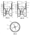
- the second item (75) can now pass into the space between the orifice (41) and the projection (53), as shown in Fig.3e.
- the actuating part (50) is released again the second item (75) falls into the channel (55) and a third item (80) moves to the orifice (41), but cannot pass through.
- the actuating part (50) can be removed by pulling it axially so that the bead (54) passes out of the groove (37).
- the actuating part (50) now functions as a cup which contains the items ready for use, as shown in Fig.4.
- a second type of dispenser (110) is shown in Figs. 5 to 7, in which like reference numerals refer to like parts in relation to Figs. 1 to 4.
- the dispenser (110) is of the same general construction as the dispenser. However, whilst in the first dispenser (10) the dispensing members (38) are adapted to move radially outwardly, in this second dispenser (110) the members (138) are adapted to move radially inwardly.
- the dispensing part (130) comprises two dispensing members (138) each of which includes a link portion (139) extending from the top of the groove (137).
- the plates (140) together define a hemispherical structure with an elliptical orifice (141) at its centre.
- the actuating part skirt (152) comprises a lower first skirt portion (156) and an upper second skirt portion (157) of reduced diameter.
- the portions (156, 157) are joined by an intermediate, inwardly inclined portion (158).
- a central projection (153) depends from the top plate of the actuating part.
- the operation of the dispenser (110) is similar to the dispenser (10) in that the tamper band (160) is first removed and the actuating part (150) is then depressed. In this dispenser (110), however, depressing the actuating part (150) causes the legs (142) to progressively contact further down the intermediate skirt portion (158), which forces the dispensing members (138) radially inwardly (Fig.7c).
- the plates (140) are formed so that they contact each other in the rest position (see Fig.5). Accordingly, when the dispensing members (138) are forced inwardly the plates (140) are forced against each other and the areas around the orifice (141) are bowed outwardly. This tends to circularise the oral orifice (141).
- spherical items (170, 175, 180) can pass through the orifice (141) in the same sequence shown for the first dispenser (10).
- the central projection (153) does not cause the members (138) to move, but does restrict dispensing of items in the same way as the projection (53) of the first embodiment.
Landscapes
- Engineering & Computer Science (AREA)
- Mechanical Engineering (AREA)
- Closures For Containers (AREA)
Abstract
A dispenser (10) is provided. The dispenser has a
container body (20) for storing a plurality of items (70,
75, 80) to be dispensed. The dispenser also has a
dispensing part (30) which has an orifice (41) and is
movable from a non-dispensing position in which items
cannot pass through the orifice to a dispensing position
in which items (70, 75, 80) can pass from the container
body (20) through the orifice (41). The dispenser
further includes an actuating part (50) operable to move
the dispensing part (30) to the dispensing position. The
dispenser is arranged so that when items pass through the
orifice they are released directly into the actuating
part (50).
Description
The present invention relates generally to a
dispenser for holding a plurality of individual items and
allowing them to be dispensed.
A common form of dispenser of this type is a tablet
dispenser for medicaments, sweeteners or the like
product. Tablet dispensers usually comprise a body for
containing a plurality of items to be dispensed, and an
actuating means operable by the user to cause an item to
be dispensed from the body. The actuating means may be,
for example, a push-button (EP 0 894 736), a rotatable
part (US 6,142,337) or a squeezable shell (WO 00/68109).
In known tablet dispensing systems the tablets are
dispensed directly out of the dispenser. For example,
medicaments are dispensed directly into the hand of the
user, and sweetening tablets are dispensed directly into
a beverage.
There are a number of disadvantages to this type of
system, for example: tablets may be misdirected and then
lost as they are dispensed; if a user's hand is required
to catch the tablets as they are dispensed this prohibits
two-handed operation of the actuating means, which may be
necessary for those without the strength or dexterity to
operate the actuating means with a single hand; the items
which will be dispensed may be water-soluble and
therefore it would be preferable not to dispense them
directly onto a user's hand; if items are dispensed
directly into a beverage the number of tablets dispensed
may be forgotten during the dispensing operation and
therefore an accurate dose will not be possible.
The present invention seeks to address the above
problems.
The present invention provides a dispenser
comprising a container body which, in use, contains a
plurality of items to be dispensed, a dispensing part
having an orifice movable from a non-dispensing position
in which items cannot pass through the orifice to a
dispensing position in which an item can pass from the
container body through the orifice, and an actuating part
operable to move the dispensing part to the dispensing
position, characterised that, the dispenser is arranged
so that, in use, items passing through the orifice are
released into the actuating part.
The present invention therefore uses the actuating
part not only to actuate item-release means, but also to
catch items as they are dispensed. Once the required
number of items has been dispensed the items can be
removed from the actuating part.
The actuating part may be removable completely from
the remainder of the dispenser so that the items can be
easily removed.
The dispenser may be adapted to dispense items
individually into the actuating part. This allows the
required number of items to be accurately dispensed into
the actuating part prior to the items leaving the
dispenser.
The dispensing orifice may be defined by one or more
dispensing members movable in response to movement of the
actuating part. The or each dispensing member may be
adapted to move radially outwardly or inwardly to move
the dispensing part to the dispensing position.
The number and form of the dispensing member/s can
be matched to any particular application. The only
essential requirement is that it/they define an orifice
adapted to restrict/allow the passage of items when the
dispensing part is in the non-dispensing/dispensing
position.
The actuating part may include a projection which,
together with the dispensing member/s, defines a
restricted dispensing zone adjacent the orifice into
which a single item can pass when the dispensing part is
moved to the dispensing position. Inclusion of the
projection therefore allows items to be dispensed
individually into the actuating part.
The projection may also be adapted to cause the
dispensing member/s to move as the actuating part is
moved. The projection therefore serves a dual function.
The dispensing part may be biassed towards the non-dispensing
position so that following the dispensing of
one or more items, the dispensing part automatically
returns to the non-dispensing position.
The dispenser may further comprise a tamperband.
The tamperband may be situated such that it must be
removed before the actuating part can be operated to move
the dispensing part. The dispenser cannot be operated
before the tamperband is removed.
Where a plurality of dispensing members are used and
they move radially outwardly to move the dispensing part
to the dispensing position, they may define a circular
orifice. In the non-dispensing position the orifice
defined by the dispensing members is smaller than an
item. When the actuating part is operated the dispensing
members move radially outwardly and increase the size of
the circular orifice.
Where the dispensing members move radially inwardly
the members may define an ovoid orifice in the non-dispensing
position. When the actuating part is operated
the dispensing members move radially inwardly and
circularise the orifice. The items are shaped such that
they cannot pass through an ovoid orifice but can pass
through a circular orifice which may have the same
circumference; for example the items could be disc-shape
or spherical.
The present invention will now be more particularly
described, by way of example, with reference to the
accompanying drawings, in which:
Referring first to Figs. 1 and 2 there is shown a
dispenser generally indicated (10) comprising a body part
(20), a dispensing part (30) and an actuating part (50)
[Fig.1 shows just the parts (20, 30) before the part (50)
has been added].
The body part (20) is a cylindrical container for
holding items to be dispensed. The body part (20) is
closed at one end by a disc-shape end plate (21), and
the dispensing part (30) is connected to the other end of
the body part (20).
Referring now also to Figs. 3a to 3f, the actuating
part (50) is a cap comprising a top plate (51) and a
cylindrical skirt (52) which depends from the periphery
of the plate (51).
The top plate (51) includes a central frustoconical
depression which forms a frustoconical projection (53) in
the interior of the actuating part (50). The projection
(53) defines an annular channel (55) around its
periphery.
At the open end of the skirt (52) is an annular bead
(54) the purpose of which is described in more detail
below.
The dispensing part (30) comprises a lower
connecting portion (31) and an upper dispensing portion
(32). The connecting portion (31) comprises a lower
tubular skirt (33) sized to fit inside the body part
(20). The outer wall of the connecting portion (31) has
a flange (34) approximately half way along its length.
The flange (34) acts as a depth stop to limit the amount
the connecting portion (31) can be inserted into the body
part (20).
Below the flange (34) the outer wall of the
connecting portion (31) has an annular groove (35) sized
and positioned so that when the connecting portion is
fully inserted into the body part (20) it aligns with an
annular bead (22) on the inner surface of the body part
(best shown in Figs. 3a to 3f). The bead (22) thereby
retains the dispensing part (30) in the body part (20).
Above the flange (34) the connecting portion (31)
extends with an upper tubular skirt (36). The upper
tubular skirt (36) includes an annular groove (37) which
is trapezoidal in section. The groove (37) receives the
bead (54) from the inside surface of the cap skirt (52)
to clip the actuating part (50) onto the dispensing part
(30) in such a way that the actuating part (50) can move
axially with respect to the dispensing part (30), with
the bead (54) sliding axially in the groove (37).
The dispensing portion (32) of the dispensing part
(30) extends from the upper tubular skirt (36). The
dispensing portion (32) comprises three identical
dispensing members (38).
Each of the members (38) includes a link portion
(39) which extends orthogonally from the upper tubular
skirt (36) to connect the member (38) to the skirt (36)
in such a way that the member (38) can resiliently flex
in the radial direction. Each member (38) further
comprises a curved plate (40) which is shaped so that
together the members (38) form a frustoconical structure
with a central circular orifice (41) at its end remote
from the link portions (38). The orifice (41) is shaped
and configured, i.e. adapted, to the items to be
dispensed.
Each of the members (38) further includes a leg (42)
which extends from the outer surface of the plate (40).
The lower edge of the skirt (52) of the actuating
part (50) is attached to the flange (34) by an annular
tamper evident band (60), the purpose of which is
described below.
The operation of the dispenser will now be described
in relation to Figs. 3a to 3f, which show the upper part
of the dispenser in an inverted, as used, state compared
to Figs.1 and 2
Fig.3a shows the dispenser in an unopened and unused
configuration. The tamper band (60) is connected between
the lower edge of the skirt (54) and the flange (34).
The actuating part (50) is thereby locked in a first axial position in which the bead (54) is at the upper end of the groove (37).
The actuating part (50) is thereby locked in a first axial position in which the bead (54) is at the upper end of the groove (37).
In the first axial position the dispensing member
legs (42) are held away from the actuating part
projection (53) and the members (38) are in a rest
position in which the orifice (41) is too small for an
item to pass through.
Fig.3b shows the dispenser with the tamper band (60)
removed. There is now a gap (G) between the lower edge
of the skirt (52) and the flange (34).
In Fig.3c the actuating part (50) has been moved to
a second, lower axial position. This is possible because
of the gap (G) and because the bead (54) can slide from
the upper end of the groove (37) to the lower end. The
movement of the actuating part (50) causes the legs (42)
to contact the projection (53) and to move progressively
down its widening exterior surface. As a result the
dispensing members (38) pivot about the intersection
between the link members (39) and the plates (40).
As the members (38) are splayed radially outwardly
the circular orifice (41) increases in size until a first
item (70) can pass through. The first item (70) passes
through the orifice (41) and onto the projection (53).
The space between the orifice (41) and the projection
(53) is sufficient only for a single item; accordingly
only a single item can be released from the orifice (41)
whilst it is at its increased size. When the actuating
part (50) is released, the resilience of the dispensing
members (38) forces the actuating part (50) back to the
first axial position, shown in Fig.3d. The first item
(70) can now fall into the channel (55) surrounding the
projection (53). A second item (75) cannot pass through
the now constricted orifice (41).
If the dispenser (10) is operated again the second
item (75) can now pass into the space between the orifice
(41) and the projection (53), as shown in Fig.3e. When
the actuating part (50) is released again the second item
(75) falls into the channel (55) and a third item (80)
moves to the orifice (41), but cannot pass through.
When the required numbers of items has been
dispensed into the channel (55) the actuating part (50)
can be removed by pulling it axially so that the bead
(54) passes out of the groove (37). The actuating part
(50) now functions as a cup which contains the items
ready for use, as shown in Fig.4.
A second type of dispenser (110) is shown in Figs. 5
to 7, in which like reference numerals refer to like
parts in relation to Figs. 1 to 4. The dispenser (110)
is of the same general construction as the dispenser.
However, whilst in the first dispenser (10) the
dispensing members (38) are adapted to move radially
outwardly, in this second dispenser (110) the members
(138) are adapted to move radially inwardly.
In this embodiment the dispensing part (130)
comprises two dispensing members (138) each of which
includes a link portion (139) extending from the top of
the groove (137). The plates (140) together define a
hemispherical structure with an elliptical orifice (141)
at its centre.
The actuating part skirt (152) comprises a lower
first skirt portion (156) and an upper second skirt
portion (157) of reduced diameter. The portions (156,
157) are joined by an intermediate, inwardly inclined
portion (158).
A central projection (153) depends from the top
plate of the actuating part.
The operation of the dispenser (110) is similar to
the dispenser (10) in that the tamper band (160) is first
removed and the actuating part (150) is then depressed.
In this dispenser (110), however, depressing the
actuating part (150) causes the legs (142) to
progressively contact further down the intermediate skirt
portion (158), which forces the dispensing members (138)
radially inwardly (Fig.7c). In this embodiment the
plates (140) are formed so that they contact each other
in the rest position (see Fig.5). Accordingly, when the
dispensing members (138) are forced inwardly the plates
(140) are forced against each other and the areas around
the orifice (141) are bowed outwardly. This tends to
circularise the oral orifice (141).
Accordingly, spherical items (170, 175, 180) can
pass through the orifice (141) in the same sequence shown
for the first dispenser (10).
The central projection (153) does not cause the
members (138) to move, but does restrict dispensing of
items in the same way as the projection (53) of the first
embodiment.
Claims (11)
- A dispenser (10) comprising:characterised in that,a container body (20) which, in use, contains a plurality of items (70, 75, 80) to be dispensed,a dispensing part(30) having an orifice (41) and being movable from a non-dispensing position in which items (70, 75, 80) cannot pass through the orifice (41) to a dispensing position in which items can pass from the container body (20) through the orifice (41), andan actuating part (50) operable to move the dispensing part (30) to the dispensing position,
the dispenser (10) is arranged so that, in use, items (70, 75, 80) passing through the orifice (41) are released into the actuating part (50). - A dispenser (10) according to claim 1, wherein the actuating part (50) is removable.
- A dispenser (10) according to claim 1 or claim 2, wherein the dispenser (10) is adapted to dispense items (70, 75, 80) individually into the actuating part (50).
- A dispenser (10) according to any of claims 1 to 3, wherein the dispensing orifice (41) is defined by one or more dispensing members (38) movable in response to movement of the actuating part (50).
- A dispenser (10) according to claim 4, wherein the or each dispensing member (38) is adapted to move radially outwardly thereby moving the dispensing part (30) to the dispensing position.
- A dispenser (10) according to claim 4, wherein the or each dispensing member (38) is adapted to move radially inwardly thereby moving the dispensing part (30) to the dispensing position.
- A dispenser (10) according to any of claims 4 to 6 wherein the actuating part (50) includes a projection (53) which, together with the dispensing member/s (38), defines a restricted dispensing zone adjacent the orifice (41) into which only a single item (70) can pass when the dispensing part (30) is moved to the dispensing position.
- A dispenser (10) according to claim 7, wherein the projection (53) is adapted to cause the dispensing member/s (38) to move as the actuating part (50) is moved.
- A dispenser (10) according to any preceding claim, wherein the dispensing part (30) is biassed towards the non-dispensing position.
- A dispenser (10) according to any preceding claim, wherein the dispenser (10) further comprises a tamper band (60) which must be removed before the actuating part (50) can be operated to move the dispensing part (30).
- A dispenser (110) according to any of claims 4 to 10, wherein in the non-dispensing position the dispensing member/s (138) define an ovoid orifice (141) and in the dispensing position the dispensing member/s (138) define a circular orifice (141).
Priority Applications (4)
| Application Number | Priority Date | Filing Date | Title |
|---|---|---|---|
| EP03017251A EP1502877A1 (en) | 2003-07-30 | 2003-07-30 | A dispenser |
| EP04741274A EP1648799B1 (en) | 2003-07-30 | 2004-07-26 | A dispenser |
| PCT/EP2004/008352 WO2005014431A1 (en) | 2003-07-30 | 2004-07-26 | A dispenser |
| DE602004010268T DE602004010268D1 (en) | 2003-07-30 | 2004-07-26 | DONOR |
Applications Claiming Priority (1)
| Application Number | Priority Date | Filing Date | Title |
|---|---|---|---|
| EP03017251A EP1502877A1 (en) | 2003-07-30 | 2003-07-30 | A dispenser |
Publications (1)
| Publication Number | Publication Date |
|---|---|
| EP1502877A1 true EP1502877A1 (en) | 2005-02-02 |
Family
ID=33522310
Family Applications (2)
| Application Number | Title | Priority Date | Filing Date |
|---|---|---|---|
| EP03017251A Withdrawn EP1502877A1 (en) | 2003-07-30 | 2003-07-30 | A dispenser |
| EP04741274A Expired - Lifetime EP1648799B1 (en) | 2003-07-30 | 2004-07-26 | A dispenser |
Family Applications After (1)
| Application Number | Title | Priority Date | Filing Date |
|---|---|---|---|
| EP04741274A Expired - Lifetime EP1648799B1 (en) | 2003-07-30 | 2004-07-26 | A dispenser |
Country Status (3)
| Country | Link |
|---|---|
| EP (2) | EP1502877A1 (en) |
| DE (1) | DE602004010268D1 (en) |
| WO (1) | WO2005014431A1 (en) |
Cited By (3)
| Publication number | Priority date | Publication date | Assignee | Title |
|---|---|---|---|---|
| KR100654182B1 (en) * | 2005-09-26 | 2006-12-06 | 씨제이 주식회사 | Container structure |
| FR2894943A1 (en) * | 2005-12-19 | 2007-06-22 | Plastohm S A Sa | DISTRIBUTOR FOR ANY PRODUCT TYPE COMPRIMES. |
| FR2967657A1 (en) * | 2010-11-18 | 2012-05-25 | Defi Internat | Beauty capsule dispenser, has receiving cap screwed onto container containing capsules, where cap is unscrewed to about specific degrees such that oval cut of cover is located in axis of hopper and capsule falls into cap |
Citations (6)
| Publication number | Priority date | Publication date | Assignee | Title |
|---|---|---|---|---|
| US3481513A (en) * | 1968-03-06 | 1969-12-02 | Gerson L Ram | Metering safety cap device |
| EP0002403A1 (en) * | 1977-11-28 | 1979-06-13 | LABORATOIRES SUPPO-STERIL Société à responsabilité limitée dite: | Counting and dispensing closure for granules disposed in a container |
| FR2625982A1 (en) * | 1988-01-19 | 1989-07-21 | Gagey Etienne | Dispenser device, particularly for pills, medicines or confectionery products |
| FR2717453A1 (en) * | 1994-03-17 | 1995-09-22 | Materiel Ste Tech Exploit | Granule distributor tube. |
| FR2764583A1 (en) * | 1997-06-17 | 1998-12-18 | Airsec Sa | Packaging tube with distributor for small pills |
| FR2788040A1 (en) * | 1998-12-31 | 2000-07-07 | Airsec Sa | DISTRIBUTOR OF OBJECTS |
-
2003
- 2003-07-30 EP EP03017251A patent/EP1502877A1/en not_active Withdrawn
-
2004
- 2004-07-26 DE DE602004010268T patent/DE602004010268D1/en not_active Expired - Lifetime
- 2004-07-26 EP EP04741274A patent/EP1648799B1/en not_active Expired - Lifetime
- 2004-07-26 WO PCT/EP2004/008352 patent/WO2005014431A1/en not_active Ceased
Patent Citations (6)
| Publication number | Priority date | Publication date | Assignee | Title |
|---|---|---|---|---|
| US3481513A (en) * | 1968-03-06 | 1969-12-02 | Gerson L Ram | Metering safety cap device |
| EP0002403A1 (en) * | 1977-11-28 | 1979-06-13 | LABORATOIRES SUPPO-STERIL Société à responsabilité limitée dite: | Counting and dispensing closure for granules disposed in a container |
| FR2625982A1 (en) * | 1988-01-19 | 1989-07-21 | Gagey Etienne | Dispenser device, particularly for pills, medicines or confectionery products |
| FR2717453A1 (en) * | 1994-03-17 | 1995-09-22 | Materiel Ste Tech Exploit | Granule distributor tube. |
| FR2764583A1 (en) * | 1997-06-17 | 1998-12-18 | Airsec Sa | Packaging tube with distributor for small pills |
| FR2788040A1 (en) * | 1998-12-31 | 2000-07-07 | Airsec Sa | DISTRIBUTOR OF OBJECTS |
Cited By (4)
| Publication number | Priority date | Publication date | Assignee | Title |
|---|---|---|---|---|
| KR100654182B1 (en) * | 2005-09-26 | 2006-12-06 | 씨제이 주식회사 | Container structure |
| FR2894943A1 (en) * | 2005-12-19 | 2007-06-22 | Plastohm S A Sa | DISTRIBUTOR FOR ANY PRODUCT TYPE COMPRIMES. |
| WO2007071837A3 (en) * | 2005-12-19 | 2007-08-16 | Plastohm Sa | Dispenser for dispensing any type of tablet-like product |
| FR2967657A1 (en) * | 2010-11-18 | 2012-05-25 | Defi Internat | Beauty capsule dispenser, has receiving cap screwed onto container containing capsules, where cap is unscrewed to about specific degrees such that oval cut of cover is located in axis of hopper and capsule falls into cap |
Also Published As
| Publication number | Publication date |
|---|---|
| WO2005014431A1 (en) | 2005-02-17 |
| EP1648799A1 (en) | 2006-04-26 |
| EP1648799B1 (en) | 2007-11-21 |
| DE602004010268D1 (en) | 2008-01-03 |
Similar Documents
| Publication | Publication Date | Title |
|---|---|---|
| US5108006A (en) | Tablet dispenser with locking means | |
| US9216852B2 (en) | Lockable dispensing package and actuator | |
| CN103998351B (en) | Sprayhead for a spray device | |
| US6164498A (en) | Pump dispenser | |
| US4572410A (en) | Safety actuator for an aerosol valve | |
| US12508612B2 (en) | Device for dispensing a fluid product | |
| US20040188473A1 (en) | Hand-held product dispensers having pressurized delivery | |
| US7044341B2 (en) | Device for packaging and dispensing a product, such as a cosmetic product | |
| US20040112924A1 (en) | Dispenser device for fitting to a receptacle provided with a valve | |
| CZ20001225A3 (en) | Dispensing apparatus | |
| JPH05146723A (en) | Device for spraying or distributing fluid | |
| US7073685B1 (en) | Dispenser of objects | |
| US3765573A (en) | Actuating cap for an aerosol device | |
| EP1727746B1 (en) | Housing and actuating apparatus and methods associated therewith | |
| US3178071A (en) | Aerosol container and dispenser | |
| US20200197967A1 (en) | Pump for cosmetic product vial, sealed under low-pressure conditions | |
| US7278556B2 (en) | Fluid product dispensing valve and fluid product dispensing device comprising same | |
| US20110121028A1 (en) | Dispenser and flexible pouch for liquid food product | |
| US3224634A (en) | Pill dispenser | |
| EP1648799B1 (en) | A dispenser | |
| TWI866101B (en) | Fluid delivery device | |
| US4848593A (en) | Granule dispensing apparatus, particularly designed for a tube of homoepathic drugs, and method for the utilization thereof | |
| JPH07327730A (en) | dispenser | |
| CN120693216A (en) | Device for dispensing fluid products | |
| EP1789344B1 (en) | Spring-loaded actuator cap |
Legal Events
| Date | Code | Title | Description |
|---|---|---|---|
| PUAI | Public reference made under article 153(3) epc to a published international application that has entered the european phase |
Free format text: ORIGINAL CODE: 0009012 |
|
| AK | Designated contracting states |
Kind code of ref document: A1 Designated state(s): AT BE BG CH CY CZ DE DK EE ES FI FR GB GR HU IE IT LI LU MC NL PT RO SE SI SK TR |
|
| AX | Request for extension of the european patent |
Extension state: AL LT LV MK |
|
| STAA | Information on the status of an ep patent application or granted ep patent |
Free format text: STATUS: THE APPLICATION HAS BEEN WITHDRAWN |
|
| 18W | Application withdrawn |
Effective date: 20050225 |