EP1502821B1 - Kabelschacht für Leistungskabel - Google Patents
Kabelschacht für Leistungskabel Download PDFInfo
- Publication number
- EP1502821B1 EP1502821B1 EP04013812A EP04013812A EP1502821B1 EP 1502821 B1 EP1502821 B1 EP 1502821B1 EP 04013812 A EP04013812 A EP 04013812A EP 04013812 A EP04013812 A EP 04013812A EP 1502821 B1 EP1502821 B1 EP 1502821B1
- Authority
- EP
- European Patent Office
- Prior art keywords
- cable
- cable duct
- duct
- conduit according
- generator
- Prior art date
- Legal status (The legal status is an assumption and is not a legal conclusion. Google has not performed a legal analysis and makes no representation as to the accuracy of the status listed.)
- Expired - Lifetime
Links
- 238000004519 manufacturing process Methods 0.000 claims abstract description 9
- 238000000034 method Methods 0.000 claims abstract description 3
- 239000007858 starting material Substances 0.000 claims description 17
- XLYOFNOQVPJJNP-UHFFFAOYSA-N water Substances O XLYOFNOQVPJJNP-UHFFFAOYSA-N 0.000 claims description 13
- 238000002485 combustion reaction Methods 0.000 claims description 7
- 229910000906 Bronze Inorganic materials 0.000 claims description 4
- 239000010974 bronze Substances 0.000 claims description 4
- KUNSUQLRTQLHQQ-UHFFFAOYSA-N copper tin Chemical compound [Cu].[Sn] KUNSUQLRTQLHQQ-UHFFFAOYSA-N 0.000 claims description 4
- 238000002347 injection Methods 0.000 claims description 2
- 239000007924 injection Substances 0.000 claims description 2
- 238000004378 air conditioning Methods 0.000 claims 1
- 238000007789 sealing Methods 0.000 claims 1
- 229920003023 plastic Polymers 0.000 description 13
- 239000004033 plastic Substances 0.000 description 13
- 238000009434 installation Methods 0.000 description 2
- 238000013016 damping Methods 0.000 description 1
- 238000006073 displacement reaction Methods 0.000 description 1
- 238000005516 engineering process Methods 0.000 description 1
- 238000001746 injection moulding Methods 0.000 description 1
- 239000002184 metal Substances 0.000 description 1
- 229910001092 metal group alloy Inorganic materials 0.000 description 1
- 238000005192 partition Methods 0.000 description 1
- 238000009417 prefabrication Methods 0.000 description 1
Images


Classifications
-
- H—ELECTRICITY
- H02—GENERATION; CONVERSION OR DISTRIBUTION OF ELECTRIC POWER
- H02G—INSTALLATION OF ELECTRIC CABLES OR LINES, OR OF COMBINED OPTICAL AND ELECTRIC CABLES OR LINES
- H02G3/00—Installations of electric cables or lines or protective tubing therefor in or on buildings, equivalent structures or vehicles
- H02G3/02—Details
- H02G3/04—Protective tubing or conduits, e.g. cable ladders or cable troughs
- H02G3/0462—Tubings, i.e. having a closed section
- H02G3/0487—Tubings, i.e. having a closed section with a non-circular cross-section
-
- B—PERFORMING OPERATIONS; TRANSPORTING
- B60—VEHICLES IN GENERAL
- B60R—VEHICLES, VEHICLE FITTINGS, OR VEHICLE PARTS, NOT OTHERWISE PROVIDED FOR
- B60R16/00—Electric or fluid circuits specially adapted for vehicles and not otherwise provided for; Arrangement of elements of electric or fluid circuits specially adapted for vehicles and not otherwise provided for
- B60R16/02—Electric or fluid circuits specially adapted for vehicles and not otherwise provided for; Arrangement of elements of electric or fluid circuits specially adapted for vehicles and not otherwise provided for electric constitutive elements
- B60R16/0207—Wire harnesses
- B60R16/0215—Protecting, fastening and routing means therefor
Definitions
- the invention relates to a cable guide for cables in internal combustion engines, with a generator connecting a generator with a cable, the cable is guided by the cable guide from the generator laterally along a crankcase and / or a cylinder head having engine at least partially to the starter. Moreover, the invention relates to a method for producing a cable guide for cables in internal combustion engines, in which the cable guide leads a cable connecting a generator with a starter.
- cables in the engine compartment must be routed during the manufacture of the engines.
- cables are laid in plastic corrugated pipes.
- the cables can be laid directly in the engine compartment and fastened by means of cable clamps.
- Plastic corrugated pipes are for example from the DE 100 48 396 Al known. From this, a plastic corrugated tube with a tubular body and with corrugations on the tubular body is known.
- the corrugated pipe can be adapted to the conditions in the engine compartment during assembly. It is attached to the engine by means of mounting clips.
- a fixing geometry abroad to provide from the longitudinal axis of the tubular body In order to make the attachment of the plastic corrugated tube easier to handle, it is proposed that a fixing geometry abroad to provide from the longitudinal axis of the tubular body.
- the Festgege geometry has a structure that allows through openings and holes fixing the geometry of the plastic tube to the engine compartment. With the help of the recesses and holes, the plastic corrugated pipe can be arranged in any form of objects. The holes are then used to attach with the help of screws and clips the plastic tube to the respective object.
- plastic corrugated pipe When mounted in a motor this means that the plastic corrugated pipe can be adapted to the conditions in the engine compartment and then fixed in the engine compartment. Threading the plastic pipe through the engine compartment is still necessary. The handling and attachment of the plastic pipe is complex and requires a degree of manual skill.
- the invention has for its object to provide a cable guide available that can be quickly and easily arranged in the engine compartment of an internal combustion engine. Furthermore, the cable guide should be inexpensive to manufacture and processing.
- the invention proposes that the cable guide is formed as a substantially dimensionally stable cable duct.
- the cable duct is dimensionally stable, it can already be adapted to the conditions in the engine compartment during its manufacture.
- the cable routing may also vary slightly, but the guidance along the sidewall of the engine is preferred.
- the fact that the cable tray is dimensionally stable, it can be easily installed in the engine compartment.
- the cables are preferably already embedded in the cable duct. There is no need to thread the cables into fixing clips. The assembly is easy.
- the production of the cable tray is inexpensive. Labor costs for the installation of the cables are reduced because the time required to install the cable duct is low.
- the cable duct has at least two mounting bushes arranged on the lateral crankcase and / or cylinder head and / or valve cover, fixing the cable duct on the crankcase and / or cylinder head and / or valve cover.
- the mounting bushings may include recesses, holes or clips, with which an attachment to the engine is possible. The attachment to the engine ensures the secure hold of the cable duct in the engine compartment.
- the cable duct is arranged on a tensioning lever of a belt tensioner and has the cable duct fixing bushes fixing on the tensioning lever of the belt tensioner. Furthermore, it is proposed according to claim 4 that the cable duct arranged on a water pump, the cable duct fixing to the water pump Has mounting bushing.
- the mounting sockets are preferably designed according to claim 5. Further attachment to the belt tensioner and to the water pump increase the fixation of the cable duct in the engine compartment. Movements and displacements of the cable duct can be better avoided.
- mounting sockets are preferably formed as holes.
- the simple clamping of the mounting sockets is ensured by the fact that the mounting sockets are preferably formed as fastening clips.
- the fastening bushes are at least partially made of bronze.
- the inner diameter or UnterlegTEN the holes is formed of bronze. This ensures that vibrations are damped.
- the cable duct is molded as an injection molded part. This allows a cost-effective production of the cable tray.
- the cable duct has an increased temperature resistance.
- a PA 66 plastic or a GF 15 GF 30 plastic is used. These plastics have the required temperature resistance and are also dimensionally stable.
- At least one additional cable can be routed in the cable duct in addition to the power cable running between the generator and the starter. It is proposed that preferably a climatic compressor connection cable, a terminal 50 cable and / or a BSD control line for the generator are guided in the cable duct. These cables with a smaller cross section than the power cable can also be laid in the cable duct and can then be inexpensively installed in the engine compartment. Threading the cables is no longer necessary.
- the cable duct is formed as a U-profile for receiving the cable.
- a closure element allows the closure of the cable tray.
- This closure element can be arranged on the top of the U-profile. It can be fastened to the U-profile with the help of clip connections or plug connections.
- the closure element can preferably also be opened in order subsequently to exchange cables or to be able to insert further cables into the cable duct.
- the U-profile can be formed twice. Then run in the cable duct two, separated by a partition shafts, in each of which cables can be laid. This increases the security of the cable tray.
- An outlet opening according to claim 11 allows easy connection of a corrugated pipe to the cable duct.
- Another object of the invention is a method for producing a cable guide for cables in internal combustion engines, in which a generator with a starter connecting and from the generator side along a crankcase and / or a cylinder head having engine at least partially run to the starter cable is assembled in a substantially dimensionally stable cable duct and in which the prefabricated cable duct attached to the crankcase and / or on the cylinder head and / or valve cover becomes.
- the method allows the prefabrication of the cable guide. This reduces the cost of laying the cable.
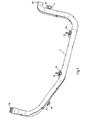
- FIG. 1 shown is a view of a cable duct 2.
- the cable duct 2 is made by injection molding and already adapted to the Eorm of the course of the cable in the engine compartment.
- a fixing bush 4 is arranged at the first end of the cable duct 2. This mounting bush 4 is used Attaching the cable duct to the tension lever of the belt tensioner of the engine.
- the mounting sockets 6a and 6b are arranged. These mounting sockets 6a and 6b allow the attachment of the cable duct 2 to the engine.
- these fastening bushes 6a and 6b are preferably arranged at the points shown.
- the mounting bushing 8 serves to attach the cable duct 2 to a water pump or to the housing of a water pump of the engine. It can be seen that the fastening bushes 4, 6, 8 have washers 10 on their inside diameters. These washers 10 are used for vibration damping and are therefore preferably made of a soft metal or a metal alloy, in particular bronze.
- the cable duct 2 is shaped at its ends such that outlet openings 3a, b have a fitting adapted to corrugated pipes.
- FIG. 2 shows a similar plan view of the cable duct 2 as in FIG. 1 illustrated, but lacks the closure element here. It can be seen that the cable duct 2 has a double U-profile. The cables can be inserted in this double U-profile. As a result, the cable duct 2 can be pre-assembled with the required cables. In each of the Shafts cables can be laid so that they are separated by the shaft walls.
- FIG. 3 shows a view of an interior of an engine compartment.
- the cable duct 2 with its mounting sockets 6 and 8.
- a cylinder head 12 a starter 14 and a water pump 16 with a drive wheel 16b.
- the cable duct 2 extends parallel to the cylinder head 12 and is attached thereto via the mounting sockets 6. At the end of the cylinder head 12, the cable duct 2 is bent downwards along the water pump 16 and the drive wheel 16b in the direction of the starter 14. Shortly before the starter 14, the cable duct 2 is bent once more by approximately 90 ° in the direction of the starter 14, thus enabling the outlet of the cable in the direction of the starter 14.
- the cable duct 2 As firmly as possible in the engine compartment, this is fixed by means of the mounting bushing 8 to the water pump 16.
- the cable duct 2 must be fixed only at three or four points, after which the laying of the cable is completed. This considerably reduces the installation costs.
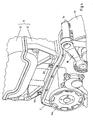
- FIG. 4 another view of the engine compartment is shown from a different perspective.
- the cable duct 2 runs between the belt tensioner 18 and water pump 16 parallel to the cylinder head 12th
- the Cable duct 12 kinked in front of the clamping lever of the belt tensioner 18 and extends between engine 11 and attachment of the tensioning lever for the belt tensioner 18.
- Below the attachment of the tensioning lever for the belt tensioner 18 of the cable shaft 2 then kinks in the direction of the generator 20 and there releases the cable.
- the cable duct 2 is additionally attached to the clamping lever of the belt tensioner 18. This can not be seen from the view shown.
- the inventive arrangement of the cable harness in the cable duct allows the pre-assembly of the cable and a simple and inexpensive attachment of the cable in the engine compartment. Threading the cables is no longer necessary.
Landscapes
- Engineering & Computer Science (AREA)
- Mechanical Engineering (AREA)
- Architecture (AREA)
- Civil Engineering (AREA)
- Structural Engineering (AREA)
- Ignition Installations For Internal Combustion Engines (AREA)
- Communication Cables (AREA)
- Supports For Pipes And Cables (AREA)
- Details Of Indoor Wiring (AREA)
- Insulated Conductors (AREA)
Description
- Die Erfindung betrifft eine Kabelführung für Kabel in Verbrennungsmotoren, mit einem einen Generator mit einem Anlasser verbindenden Kabel, wobei das Kabel durch die Kabelführung vom Generator seitlich entlang eines ein Kurbelgehäuse und/oder einen Zylinderkopf aufweisenden Triebswerks zumindest teilweise zum Anlasser geführt ist. Darüber hinaus betrifft die Erfindung ein Verfahren zur Herstellung einer Kabelführung für Kabel in Verbrennungsmotoren, bei welchem die Kabelführung ein einen Generator mit einem Anlasser verbindendes Kabel führt.
- Heutzutage ist die Elektrik in Verbrennungsmotoren ebenso wichtig wie die Technik der Motoren selber. Kabel im Motorraum müssen bei der Herstellung der Motoren verlegt werden. Hierzu ist bekannt, dass Kabel in Kunststoffwellrohren verlegt werden. Außerdem können die Kabel direkt im Motorraum verlegt werden und mit Hilfe von Kabelschellen befestigt werden.
- Kunststoffwellrohre sind beispielsweise aus der
DE 100 48 396 Al bekannt. Hieraus ist ein Kunststoffwellrohr mit einem Rohrkörper sowie mit Wellungen an dem Rohrkörper bekannt. Das Wellrohr lässt sich an die Gegebenheiten im Motorraum bei der Montage anpassen. Es wird mit Hilfe von Montageclips am Motor befestigt. Um nun die Befestigung des Kunststoffwellrohres leichter handhabbar zu machen, wird vorgeschlagen, eine Festlegungsgeometrie auswärts von der Längsachse des Rohrkörpers vorzusehen. Die Festlegungsgeometrie weist eine Struktur auf, die durch Öffnungen und Bohrungen die Festlegung der Geometrie des Kunststoffrohres an den Motorraum ermöglicht. Mit Hilfe der Aussparungen und Bohrungen kann das Kunststoffwellrohr in beliebiger Form an Gegenständen angeordnet werden. Die Bohrungen dienen dann dazu, mit Hilfe von Schrauben und Befestigungsclips das Kunststoffrohr an dem jeweiligen Gegenstand zu befestigen. - Bei der Montage in einem Motor bedeutet dies, dass das Kunststoffwellrohr an die Gegebenheiten im Motorraum angepasst werden kann und dann im Motorraum befestigt wird. Ein Fädeln des Kunststoffrohres durch den Motorraum ist dabei immer noch notwendig. Die Handhabung und Befestigung des Kunststoffrohres ist aufwändig und erfordert ein gewisses Maß an handwerklichem Geschick.
- Aufgrund dieser Nachteile liegt der Erfindung die Aufgabe zugrunde, eine Kabelführung zur Verfügung zu stellen, die schnell und einfach im Motorraum eines Verbrennungsmotors angeordnet werden kann. Ferner soll die Kabelführung kostengünstig in der Herstellung und Verarbeitung sein.
- Zur Lösung dieser aus dem Stand der Technik hergeleiteten und zuvor aufgezeigten Aufgabe schlägt die Erfindung vor, dass die Kabelführung als ein im Wesentlichen formstabiler Kabelschacht gebildet ist.
- Dadurch, dass der Kabelschacht formstabil ist, kann er bei seiner Herstellung bereits an die Gegebenheiten im Motorraum angepasst werden. Vorzugsweise wird das zu führende Kabel vom Generator zum Anlasser geführt. Dabei wird es ausgehend vom Generator am Spannhebel für den Riemenspanner vorbei in Richtung der Aussenkante des Triebwerks geführt. Danach ist der Kabelschacht parallel zur Seitenwand des Triebwerks geführt und weist am Ende eine Biegung entlang der Wasserpumpe in Richtung des Anlassers auf. Je nach Form des zu bestückenden Motors, kann die Kabelführung auch leicht variieren, jedoch wird die Führung entlang der Seitenwand des Triebwerks bevorzugt. Dadurch, dass der Kabelschacht formstabil gebildet ist, lässt er sich leicht in den Motorraum einbauen. Die Kabel sind vorzugsweise bereits im Kabelschacht eingelassen. Ein Einfädeln der Kabel in Befestigungsclips entfällt. Die Montage ist einfach. Die Herstellung des Kabelschachts ist kostengünstig. Lohnkosten für die Installation der Kabel werden reduziert, da der Zeitaufwand zur Installation des Kabelschachts gering ist.
- Es wird bevorzugt, dass der Kabelschacht zumindest zwei am seitlichen Kurbelgehäuse und/oder Zylinderkopf und/oder Ventildeckel angeordnete, den Kabelschacht am Kurbelgehäuse und/oder Zylinderkopf und/oder Ventildeckel fixierende Befestigungsbuchsen aufweist. Die Befestigungsbuchsen können Aussparungen, Bohrungen oder Clips enthalten, mit denen eine Befestigung am Triebwerk möglich ist. Durch die Befestigung am Triebwerk ist der sichere Halt des Kabelschachts im Motorraum gewährleistet.
- Gemäß Anspruch 3 wird vorgeschlagen, dass der Kabelschacht an einem Spannhebel eines Riemenspanners angeordnet ist und den Kabelschacht am Spannhebel des Riemenspanners fixierende Befestigungsbuchsen aufweist. Ferner wird gemäß Anspruch 4 vorgeschlagen, dass der Kabelschacht eine an einer Wasserpumpe angeordnete, den Kabelschacht an der Wasserpumpe fixierende Befestigungsbuchse aufweist. Die Befestigungsbuchsen sind vorzugsweise gemäß Anspruch 5 gestaltet. Die weitere Befestigung am Riemenspanner und an der Wasserpumpe erhöhen die Fixierung des Kabelschachts im Motorraum. Bewegungen und Verschiebungen des Kabelschachtes können so besser vermieden werden.
- Die Befestigung mit Hilfe von Schrauben und Nuten ist dadurch gewährleistet, dass die Befestigungsbuchsen vorzugsweise als Bohrungen gebildet sind. Das einfache Anklemmen der Befestigungsbuchsen wird dadurch gewährleistet, dass die Befestigungsbuchsen bevorzugt als Befestigungsclips gebildet sind.
- Im Motorraum treten Vibrationen auf, die die Befestigung zwischen Kabelschacht und Motorelementen lösen könnten. Daher wird vorgeschlagen, dass die Befestigungsbuchsen zumindest teilweise aus Bronze gebildet sind. Insbesondere wird vorgeschlagen, dass der Innendurchmesser oder auch Unterlegschreiben der Bohrungen aus Bronze gebildet ist. Dadurch wird gewährleistet, dass Schwingungen gedämpft werden.
- Vorzugsweise wird der Kabelschacht als Spritzgussteil geformt. Dies ermöglicht eine kostengünstige Herstellung des Kabelschachts.
- Da insbesondere im Motorraum hohe Temperaturen auftreten und die Sicherheit im Fahrzeug sehr wichtig ist, wird vorgeschlagen, dass der Kabelschacht eine erhöhte Temperaturfestigkeit aufweist. Hierbei wird vorzugsweise ein PA 66 Kunststoff bzw. ein GF 15- GF 30 Kunststoff verwendet. Diese Kunststoffe weisen die geforderte Temperaturfestigkeit auf und sind ebenfalls formstabil.
- Um die Kosten für die Kabelverlegung weiter zu reduzieren, kann neben dem zwischen Generator und Anlasser verlaufenden Leistungskabel zumindest ein weiteres Kabel im Kabelschacht geführt werden. Es wird vorgeschlagen, dass vorzugsweise ein Klimakompressoranschlusskabel, ein Klemme 50 Kabel und/oder eine BSD Steuerleitung für den Generator im Kabelschacht geführt sind. Diese Kabel mit einem geringeren Querschnitt als das Leistungskabel lassen sich ebenfalls im Kabelschacht verlegen und können dann kostengünstig im Motorraum eingebaut werden. Ein Fädeln der Kabel ist nicht mehr erforderlich.
- Vorzugsweise wird der Kabelschacht als U-Profil zur Aufnahme der Kabel gebildet. Ein Verschlusselement ermöglicht das Verschließen des Kabelschachts. Dieses Verschlusselement kann auf der Oberseite des U-Profils angeordnet sein. Es kann mit Hilfe von Clipverbindungen oder Steckverbindungen am U-Profil befestig werden. Das Verschlusselement lässt sich vorzugsweise auch öffnen, um nachträglich Kabel auszutauschen oder weitere Kabel in den Kabelschacht einfügen zu können. Auch kann das U-Profil doppelt gebildet sein. Dann verlaufen im Kabelschacht zwei, durch eine Trennwand getrennte Schächte, in die jeweils Kabel verlegt werden können. Dies erhöht die Sicherheit des Kabelschachts.
- Eine Austrittsöffnung nach Anspruch 11 ermöglicht den problemlosen Anschluss eines Wellrohres an den Kabelschacht.
- Ein weiterer Gegenstand der Erfindung ist ein Verfahren zur Herstellung einer Kabelführung für Kabel in Verbrennungsmotoren, bei welchem ein einen Generator mit einem Anlasser verbindendes und vom Generator seitlich entlang eines ein Kurbelgehäuse und/oder einen Zylinderkopf aufweisenden Triebwerks zumindest teilweise zum Anlasser geführtes Kabel in einem im Wesentlichen formstabilen Kabelschacht konfektioniert wird und bei welchem der konfektionierte Kabelschacht am Kurbelgehäuse und/oder am Zylinderkopf und/oder Ventildeckel befestigt wird.
- Das Verfahren ermöglicht das Vorkonfektionieren der Kabelführung. Dadurch werden die Kosten für die Verlegung des Kabels reduziert.
- Die Erfindung wird nachfolgend anhand einer ein Ausführungsbeispiel zeigenden Zeichnungen näher erläutert. In der Zeichnung zeigt:
- Fig. 1
- eine Ansicht eines Kabelschachts;
- Fig. 2
- eine weitere Ansicht eines Kabelschachts ohne Verschlusselement;
- Fig. 3
- eine Ansicht eines Verlaufs eines Kabelschachts im Motorraum;
- Fig. 4
- eine weitere Ansicht eines Verlaufs eines Kabelschachts in einem Motorraum.
- In
Figur 1 dargestellt ist eine Ansicht eines Kabelschachts 2. Der Kabelschacht 2 ist im Spritzgussverfahren hergestellt und bereits an die Eorm des Kabelverlaufs im Motorraum angepasst. Am ersten Ende des Kabelschachts 2 ist eine Befestigungsbuchse 4 angeordnet. Diese Befestigungsbuchse 4 dient der Befestigung des Kabelschachts am Spannhebel des Riemenspanners des Motors. - Im weiteren Verlauf des Kabelschachts 2 sind die Befestigungsbuchsen 6a und 6b angeordnet. Diese Befestigungsbuchsen 6a und 6b ermöglichen die Befestigung des Kabelschachts 2 am Triebwerk. Hier insbesondere am Zylinderkopf 12, am Kurbelgehäuse oder am ventildeckel 13. Da das Kabel vorzugsweise an der Seitenwand des Triebwerks vorbei geführt wird, sind diese Befestigungsbuchsen 6a und 6b bevorzugt an den gezeigten Stellen angeordnet.
- Im weiteren Verlauf des Kabelschachts 2 ist die Befestigungsbuchse 8 angeordnet. Die Befestigungsbuchse 8 dient der Befestigung des Kabelschachts 2 an einer Wasserpumpe bzw. am Gehäuse einer Wasserpumpe des Motors. Zu erkennen ist, dass die Befestigungsbuchsen 4, 6, 8 an ihren Innendurchmessern Unterlegscheiben 10 aufweisen. Diese Unterlegscheiben 10 dienen der Schwingungsdämpfung und sind deshalb vorzugsweise aus einem weichen Metall oder einer Metall-Legierung, insbesondere Bronze, gebildet.
- Der Kabelschacht 2 ist an seinen Enden derart geformt, dass Austrittsöffnungen 3a, b eine an Wellrohre angepasste Passform aufweisen.
-
Figur 2 zeigt eine ähnliche Draufsicht auf den Kabelschacht 2 wie die inFigur 1 dargestellte, jedoch fehlt hier das Verschlusselement. Zu erkennen ist, dass der Kabelschacht 2 ein doppeltes U-Profil aufweist. In diesem doppelten U-Profil können die Kabel eingelegt werden. Dadurch lässt sich der Kabelschacht 2 mit den erforderlichen Kabeln vorkonfektionieren. In jedem der Schächte können Kabel so verlegt werden, dass sie durch die Schachtwände voneinander getrennt sind. -
Figur 3 zeigt eine Ansicht eines Innenraums eines Motorraums. Zu erkennen ist der Kabelschacht 2 mit seinen Befestigungsbuchsen 6 und 8. Ferner ist zu erkennen ein Zylinderkopf 12, ein Anlasser 14 und eine Wasserpumpe 16 mit einem Antriebsrad 16b. - Wie aus der
Figur 3 zu erkennen ist, verläuft der Kabelschacht 2 parallel zum Zylinderkopf 12 und ist daran über die Befestigungsbuchsen 6 befestigt. Am Ende des Zylinderkopfes 12 ist der Kabelschacht 2 entlang der Wasserpumpe 16 und der Antriebsrades 16b in Richtung des Anlassers 14 nach unten gebogen. Kurz vor dem Anlasser 14 ist der Kabelschacht 2 ein weiteres Mal um ca. 90° in Richtung der Anlassers 14 gebogen und ermöglicht so den Auslass des Kabels in Richtung des Anlassers 14. - Um den Kabelschacht 2 möglichst fest im Motorraum anzuordnen, ist dieser mit Hilfe der Befestigungsbuchse 8 an der Wasserpumpe 16 befestigt. Durch die gezeigte Anordnung muss der Kabelschacht 2 nur an drei bzw. vier Punkten fixiert werden, wonach die Verlegung des Kabels beendet ist. Dies reduziert die Verlegungskosten erheblich.
- In
Figur 4 ist eine weitere Ansicht des Motorraums aus einer anderen Perspektive dargestellt. Neben den inFigur 3 gezeigten Elementen des Motorraums zeigtFigur 4 zusätzlich einen Ventildeckel 13, einen Spannhebel eines Riemenspanners 18 und einen Generator 20. Wie aus derFigur 4 zu erkennen ist, verläuft der Kabelschacht 2 zwischen Riemenspanner 18 und Wasserpumpe 16 parallel zum Zylinderkopf 12 . In Richtung des Generators 20 ist der Kabelschacht 12 vor dem Spannhebel des Riemenspanners 18 abgeknickt und verläuft zwischen Triebwerk 11 und Befestigung des Spannhebels für den Riemenspanner 18. Unterhalb der Befestigung des Spannhebels für den Riemenspanner 18 knickt der Kabelschacht 2 dann ab in Richtung des Generators 20 und gibt dort das Kabel frei. Der Kabelschacht 2 ist zusätzlich am Spannhebel des Riemenspanners 18 befestigt. Dies ist aus der gezeigten Ansicht nicht zu erkennen. - Die erfindungsgemäße Anordnung des Kabelstrangs im Kabelschacht ermöglicht das vorkonfektionieren der Kabel und ein einfaches und kostengünstiges Anbringen der Kabel im Motorraum. Ein Fädeln der Kabel ist nicht mehr notwendig.
-
- 2
- Kabelschacht
- 3
- Austrittsöffnung
- 4, 6, 8
- Befestigungsbuchse
- 10
- Unterlegscheiben
- 11
- Triebwerk
- 12
- Zylinderkopf
- 13
- Ventildeckel
- 14
- Anlasser
- 16
- Wasserpumpe
- 16b
- Antriebsrad
- 18
- Spannhebel
- 20
- Generator
Claims (12)
- Kabelführung für Kabel in Verbrennungsmotoren, mit einem einen Generator (20) mit einem Anlasser (14) verbindenden Kabel, wobei das Kabel durch die Kabelführung vom Generator (20) seitlich entlang eines ein Kurbelgehäuse und/oder einen Zylinderkopf (12) aufweisenden Triebwerks (11) zumindest teilweise zum Anlasser (14) geführt ist,
dadurch gekennzeichnet,
dass die Kabelführung als ein im Wesentlichen formstabiler Kabelschacht (2) gebildet ist. - Kabelführung nach Anspruch 1,
dadurch gekennzeichnet,
dass der Kabelschacht (2) zumindest zwei am seitlichen Kurbelgehäuse und/oder Zylinderkopf (12) und/oder Ventildeckel (13) angeordnete, den Kabelschacht (2) am Kurbelgehäuse und/oder Zylinderkopf (12) und/oder Ventildeckel (13) fixierende Befestigungsbuchsen (6) aufweist. - Kabelführung nach Anspruch 1 oder 2,
dadurch gekennzeichnet,
dass der Kabelschacht (2) eine an einem Spannhebel (18) eines Riemenspanners angeordnete, den Kabelschacht (2) am Spannhebel (18) des Riemenspanners fixierende Befestigungsbuchse (4) - aufweist. - Kabelführung nach einem der Ansprüche 1 bis 3,
dadurch gekennzeichnet,
dass der Kabelschacht (2) eine an einer Wasserpumpe (16) angeordnete, den Kabelschacht (2) an der Wasserpumpe (16) fixierende Befestigungsbuchse (8) aufweist. - Kabelführung nach einem der Ansprüche 2 bis 4,
dadurch gekennzeichnet,
dass die Befestigungsbuchsen (4, 6, 8) als Befestigungsclips und/oder als Bohrungen gebildet sind. - Kabelführung nach einem der Ansprüche 2 bis 5,
dadurch gekennzeichnet,
dass die Befestigungsbuchsen (4, 6, 8) zumindest teilweise aus Bronze gebildet sind. - Kabelführung nach einem der Ansprüche 1 bis 6,
dadurch gekennzeichnet,
dass der Kabelschacht (2) als Spritzgussteil geformt ist. - Kabelführung nach einem der Ansprüche 1 bis 7,
dadurch gekennzeichnet,
dass der Kabelschacht (2) eine erhöhte Temperaturfestigkeit aufweist. - Kabelführung nach einem der Ansprüche 1 bis 8,
dadurch gekennzeichnet,
dass ein Klimakompressoranschlusskabel, ein Klemme 50 Kabel und/oder eine BSD Steuerleitung für den Generator (10) im Kabelschacht (2) geführt sind. - Kabelführung nach einem der Ansprüche 1 bis 9,
dadurch gekennzeichnet,
dass der Kabelschacht (2) ein U-Profil zur Aufnahme der Kabel aufweist und dass der Kabelschacht (2) durch ein Verschlusselement verschließbar ist. - Kabelführung nach einem der Anschlüsse 1 bis 10,
dadurch gekennzeichnet,
dass zumindest eine Austrittöffnung (3a, b) des Kabelschachts (2) eine zur Aufnahme eines Wellrohres gebildete Passform aufweist. - Verfahren zur Herstellung einer Kabelführung für Kabel in Verbrennungsmotoren, bei welchem ein einen Generator mit einem Anlasser verbindendes und vom Generator seitlich entlang eines ein Kurbelgehäuse und/oder einen Zylinderkopf aufweisenden Triebwerks zumindest teilweise zum Anlasser geführtes Kabel in einem im Wesentlichen formstabilen Kabelschacht konfektioniert wird und bei welchem der konfektionierte Kabelschacht am Kurbelgehäuse und/oder am Zylinderkopf und/oder am Ventildeckel befestigt wird.
Applications Claiming Priority (2)
| Application Number | Priority Date | Filing Date | Title |
|---|---|---|---|
| DE10335202 | 2003-07-30 | ||
| DE10335202A DE10335202B4 (de) | 2003-07-30 | 2003-07-30 | Kabelschacht für Leistungskabel |
Publications (2)
| Publication Number | Publication Date |
|---|---|
| EP1502821A1 EP1502821A1 (de) | 2005-02-02 |
| EP1502821B1 true EP1502821B1 (de) | 2010-05-12 |
Family
ID=33521519
Family Applications (1)
| Application Number | Title | Priority Date | Filing Date |
|---|---|---|---|
| EP04013812A Expired - Lifetime EP1502821B1 (de) | 2003-07-30 | 2004-06-11 | Kabelschacht für Leistungskabel |
Country Status (3)
| Country | Link |
|---|---|
| EP (1) | EP1502821B1 (de) |
| AT (1) | ATE467532T1 (de) |
| DE (3) | DE10335202B4 (de) |
Cited By (1)
| Publication number | Priority date | Publication date | Assignee | Title |
|---|---|---|---|---|
| FR3163504A1 (fr) * | 2024-06-17 | 2025-12-19 | Stellantis Auto Sas | Gaine pour le maintien d’un faisceau électrique dans un véhicule automobile et un élément de support de la gaine |
Families Citing this family (3)
| Publication number | Priority date | Publication date | Assignee | Title |
|---|---|---|---|---|
| DE102008003332B4 (de) | 2008-01-07 | 2017-01-19 | Auto-Kabel Management Gmbh | Formstabiler Kabelstrang für die Motorraumverkabelung |
| FR3005376B1 (fr) * | 2013-05-06 | 2016-09-02 | Renault Sa | Goulotte pour un systeme de motorisation de vehicule. |
| FR3148329A1 (fr) * | 2023-04-26 | 2024-11-01 | Renault S.A.S | Dispositif de câblage pour un véhicule automobile |
Family Cites Families (7)
| Publication number | Priority date | Publication date | Assignee | Title |
|---|---|---|---|---|
| JPS62129708U (de) * | 1986-02-07 | 1987-08-17 | ||
| ES2074894T3 (es) * | 1991-10-08 | 1995-09-16 | Controle Measure Regulation | Conducto de distribucion mixto para cables de mediciones de corriente debil y cables de encendido de alta tension de motores de explosion. |
| DE4414662C2 (de) * | 1993-05-07 | 2002-05-08 | Volkswagen Ag | Kabelführung im Aggregatraum eines Kraftfahrzeuges |
| EP0900698B1 (de) * | 1997-09-04 | 2003-04-16 | Delphi Automotive Systems Deutschland GmbH | Zündungsschutzsystem |
| DE29917212U1 (de) * | 1999-09-30 | 2001-02-15 | Fränkische Rohrwerke Gebr. Kirchner GmbH + Co., 97486 Königsberg | Wellrohrbefestigungseinrichtung |
| AT408640B (de) * | 2000-03-30 | 2002-01-25 | Jenbacher Ag | Kanalförmige anschlussvorrichtung für elektrische leitungen von verbrennungsmotoren |
| JP3791372B2 (ja) * | 2001-09-10 | 2006-06-28 | 住友電装株式会社 | ワイヤハーネス用プロテクタ |
-
2003
- 2003-07-30 DE DE10335202A patent/DE10335202B4/de not_active Expired - Fee Related
-
2004
- 2004-06-11 EP EP04013812A patent/EP1502821B1/de not_active Expired - Lifetime
- 2004-06-11 DE DE202004021673U patent/DE202004021673U1/de not_active Expired - Lifetime
- 2004-06-11 AT AT04013812T patent/ATE467532T1/de active
- 2004-06-11 DE DE502004011150T patent/DE502004011150D1/de not_active Expired - Lifetime
Cited By (1)
| Publication number | Priority date | Publication date | Assignee | Title |
|---|---|---|---|---|
| FR3163504A1 (fr) * | 2024-06-17 | 2025-12-19 | Stellantis Auto Sas | Gaine pour le maintien d’un faisceau électrique dans un véhicule automobile et un élément de support de la gaine |
Also Published As
| Publication number | Publication date |
|---|---|
| EP1502821A1 (de) | 2005-02-02 |
| DE202004021673U1 (de) | 2010-03-04 |
| DE10335202A1 (de) | 2005-02-24 |
| DE502004011150D1 (de) | 2010-06-24 |
| ATE467532T1 (de) | 2010-05-15 |
| DE10335202B4 (de) | 2010-06-10 |
Similar Documents
| Publication | Publication Date | Title |
|---|---|---|
| EP1729388B1 (de) | Befestigungsvorrichtung für mehrere Leitungen | |
| DE102017215309B4 (de) | Schellenvorpositionierung und Kabelbaum | |
| EP2212502A1 (de) | Türantrieb mit einer antriebseinheit | |
| DE102010047464B4 (de) | Befestigungsanordnung | |
| EP1291216B1 (de) | Rahmen für ein Fahrzeug-Schiebedach oder -Schiebehebedach | |
| DE102017215423B4 (de) | Schellenvorpositionierung, Kabelbaum und Befestigungsstruktur von einem Kabelbaum | |
| DE102012020861A1 (de) | Ablaufvorrichtung zum Abführen von Flüssigkeit aus dem Wasserkasten eines Kraftfahrzeuges | |
| DE10335202B4 (de) | Kabelschacht für Leistungskabel | |
| EP0872632B1 (de) | Ölwanne für Verbrennungsmotoren | |
| DE102010005829A1 (de) | Transporthilfe für einen Kraftfahrzeugmotor, Motor mit einer Transporthilfe sowie Koppelelement für eine Hebe- und/oder Transporteinrichtung | |
| DE102004061381A1 (de) | Abgasklappeneinrichtung | |
| EP1541905B1 (de) | Flachdichtung | |
| DE102010022117B4 (de) | Lärmschutzvorrichtung zur Geräuschreduzierung von Verbrennungsmotoren | |
| EP0589269B1 (de) | Selbsteinstellbarer Drahtzug | |
| WO2001034421A1 (de) | Befestigung einer getriebeschaltung in einem kraftfahrzeug | |
| DE19533419B4 (de) | Zylinderkopfhaube | |
| EP4194326A1 (de) | Antriebsanordnung eines elektrofahrrads | |
| EP2067672B1 (de) | Scheibenwischvorrichtung für ein Kraftfahrzeug | |
| DE102012015747B4 (de) | Zylinderkopfhaube eines Verbrennungsmotors eines Kraftfahrzeugs | |
| DE102016005390A1 (de) | Befestigung einer Motorgetriebeeinheit | |
| DE102020118276A1 (de) | Kabelclip | |
| DE4300968A1 (en) | Cable harness support for, e.g. motor vehicle's speedometer - uses brake hose as core for helical winding of harness as safeguard against vibration or torsion | |
| DE112006003581T5 (de) | Halterung | |
| DE102016003692A1 (de) | Führungselement zum Führen wenigstens eines in einem Fahrzeug zu verbauenden Leitungselements, sowie Fahrzeug mit einem solchen Führungselement | |
| DE102006036678A1 (de) | Befestigung von Leitungen in/an Fahrzeugen mittels Magnethalterungen |
Legal Events
| Date | Code | Title | Description |
|---|---|---|---|
| PUAI | Public reference made under article 153(3) epc to a published international application that has entered the european phase |
Free format text: ORIGINAL CODE: 0009012 |
|
| AK | Designated contracting states |
Kind code of ref document: A1 Designated state(s): AT BE BG CH CY CZ DE DK EE ES FI FR GB GR HU IE IT LI LU MC NL PL PT RO SE SI SK TR |
|
| AX | Request for extension of the european patent |
Extension state: AL HR LT LV MK |
|
| AKX | Designation fees paid | ||
| 17P | Request for examination filed |
Effective date: 20050713 |
|
| RBV | Designated contracting states (corrected) |
Designated state(s): AT BE BG CH CY CZ DE DK EE ES FI FR GB GR HU IE IT LI LU MC NL PL PT RO SE SI SK TR |
|
| REG | Reference to a national code |
Ref country code: DE Ref legal event code: 8566 |
|
| GRAP | Despatch of communication of intention to grant a patent |
Free format text: ORIGINAL CODE: EPIDOSNIGR1 |
|
| GRAS | Grant fee paid |
Free format text: ORIGINAL CODE: EPIDOSNIGR3 |
|
| GRAA | (expected) grant |
Free format text: ORIGINAL CODE: 0009210 |
|
| AK | Designated contracting states |
Kind code of ref document: B1 Designated state(s): AT BE BG CH CY CZ DE DK EE ES FI FR GB GR HU IE IT LI LU MC NL PL PT RO SE SI SK TR |
|
| REG | Reference to a national code |
Ref country code: GB Ref legal event code: FG4D Free format text: NOT ENGLISH |
|
| REG | Reference to a national code |
Ref country code: CH Ref legal event code: EP |
|
| REG | Reference to a national code |
Ref country code: IE Ref legal event code: FG4D Free format text: LANGUAGE OF EP DOCUMENT: GERMAN |
|
| REF | Corresponds to: |
Ref document number: 502004011150 Country of ref document: DE Date of ref document: 20100624 Kind code of ref document: P |
|
| REG | Reference to a national code |
Ref country code: NL Ref legal event code: VDEP Effective date: 20100512 |
|
| PG25 | Lapsed in a contracting state [announced via postgrant information from national office to epo] |
Ref country code: NL Free format text: LAPSE BECAUSE OF FAILURE TO SUBMIT A TRANSLATION OF THE DESCRIPTION OR TO PAY THE FEE WITHIN THE PRESCRIBED TIME-LIMIT Effective date: 20100512 Ref country code: ES Free format text: LAPSE BECAUSE OF FAILURE TO SUBMIT A TRANSLATION OF THE DESCRIPTION OR TO PAY THE FEE WITHIN THE PRESCRIBED TIME-LIMIT Effective date: 20100823 Ref country code: SE Free format text: LAPSE BECAUSE OF FAILURE TO SUBMIT A TRANSLATION OF THE DESCRIPTION OR TO PAY THE FEE WITHIN THE PRESCRIBED TIME-LIMIT Effective date: 20100512 |
|
| PG25 | Lapsed in a contracting state [announced via postgrant information from national office to epo] |
Ref country code: FI Free format text: LAPSE BECAUSE OF FAILURE TO SUBMIT A TRANSLATION OF THE DESCRIPTION OR TO PAY THE FEE WITHIN THE PRESCRIBED TIME-LIMIT Effective date: 20100512 Ref country code: SI Free format text: LAPSE BECAUSE OF FAILURE TO SUBMIT A TRANSLATION OF THE DESCRIPTION OR TO PAY THE FEE WITHIN THE PRESCRIBED TIME-LIMIT Effective date: 20100512 |
|
| REG | Reference to a national code |
Ref country code: IE Ref legal event code: FD4D |
|
| BERE | Be: lapsed |
Owner name: AUTO KABEL MANAGEMENTGESELLSCHAFT MBH Effective date: 20100630 |
|
| PG25 | Lapsed in a contracting state [announced via postgrant information from national office to epo] |
Ref country code: PL Free format text: LAPSE BECAUSE OF FAILURE TO SUBMIT A TRANSLATION OF THE DESCRIPTION OR TO PAY THE FEE WITHIN THE PRESCRIBED TIME-LIMIT Effective date: 20100512 Ref country code: GR Free format text: LAPSE BECAUSE OF FAILURE TO SUBMIT A TRANSLATION OF THE DESCRIPTION OR TO PAY THE FEE WITHIN THE PRESCRIBED TIME-LIMIT Effective date: 20100813 Ref country code: CY Free format text: LAPSE BECAUSE OF FAILURE TO SUBMIT A TRANSLATION OF THE DESCRIPTION OR TO PAY THE FEE WITHIN THE PRESCRIBED TIME-LIMIT Effective date: 20100512 |
|
| PG25 | Lapsed in a contracting state [announced via postgrant information from national office to epo] |
Ref country code: PT Free format text: LAPSE BECAUSE OF FAILURE TO SUBMIT A TRANSLATION OF THE DESCRIPTION OR TO PAY THE FEE WITHIN THE PRESCRIBED TIME-LIMIT Effective date: 20100913 Ref country code: MC Free format text: LAPSE BECAUSE OF NON-PAYMENT OF DUE FEES Effective date: 20100630 Ref country code: EE Free format text: LAPSE BECAUSE OF FAILURE TO SUBMIT A TRANSLATION OF THE DESCRIPTION OR TO PAY THE FEE WITHIN THE PRESCRIBED TIME-LIMIT Effective date: 20100512 Ref country code: DK Free format text: LAPSE BECAUSE OF FAILURE TO SUBMIT A TRANSLATION OF THE DESCRIPTION OR TO PAY THE FEE WITHIN THE PRESCRIBED TIME-LIMIT Effective date: 20100512 Ref country code: IE Free format text: LAPSE BECAUSE OF FAILURE TO SUBMIT A TRANSLATION OF THE DESCRIPTION OR TO PAY THE FEE WITHIN THE PRESCRIBED TIME-LIMIT Effective date: 20100512 |
|
| REG | Reference to a national code |
Ref country code: CH Ref legal event code: PL |
|
| PG25 | Lapsed in a contracting state [announced via postgrant information from national office to epo] |
Ref country code: SK Free format text: LAPSE BECAUSE OF FAILURE TO SUBMIT A TRANSLATION OF THE DESCRIPTION OR TO PAY THE FEE WITHIN THE PRESCRIBED TIME-LIMIT Effective date: 20100512 Ref country code: RO Free format text: LAPSE BECAUSE OF FAILURE TO SUBMIT A TRANSLATION OF THE DESCRIPTION OR TO PAY THE FEE WITHIN THE PRESCRIBED TIME-LIMIT Effective date: 20100512 |
|
| PLBE | No opposition filed within time limit |
Free format text: ORIGINAL CODE: 0009261 |
|
| STAA | Information on the status of an ep patent application or granted ep patent |
Free format text: STATUS: NO OPPOSITION FILED WITHIN TIME LIMIT |
|
| PG25 | Lapsed in a contracting state [announced via postgrant information from national office to epo] |
Ref country code: IT Free format text: LAPSE BECAUSE OF FAILURE TO SUBMIT A TRANSLATION OF THE DESCRIPTION OR TO PAY THE FEE WITHIN THE PRESCRIBED TIME-LIMIT Effective date: 20100512 |
|
| 26N | No opposition filed |
Effective date: 20110215 |
|
| PG25 | Lapsed in a contracting state [announced via postgrant information from national office to epo] |
Ref country code: CH Free format text: LAPSE BECAUSE OF NON-PAYMENT OF DUE FEES Effective date: 20100630 Ref country code: LI Free format text: LAPSE BECAUSE OF NON-PAYMENT OF DUE FEES Effective date: 20100630 |
|
| REG | Reference to a national code |
Ref country code: DE Ref legal event code: R097 Ref document number: 502004011150 Country of ref document: DE Effective date: 20110214 |
|
| PG25 | Lapsed in a contracting state [announced via postgrant information from national office to epo] |
Ref country code: BE Free format text: LAPSE BECAUSE OF NON-PAYMENT OF DUE FEES Effective date: 20100630 |
|
| PG25 | Lapsed in a contracting state [announced via postgrant information from national office to epo] |
Ref country code: LU Free format text: LAPSE BECAUSE OF NON-PAYMENT OF DUE FEES Effective date: 20100611 Ref country code: HU Free format text: LAPSE BECAUSE OF FAILURE TO SUBMIT A TRANSLATION OF THE DESCRIPTION OR TO PAY THE FEE WITHIN THE PRESCRIBED TIME-LIMIT Effective date: 20101113 Ref country code: BG Free format text: LAPSE BECAUSE OF FAILURE TO SUBMIT A TRANSLATION OF THE DESCRIPTION OR TO PAY THE FEE WITHIN THE PRESCRIBED TIME-LIMIT Effective date: 20100512 |
|
| PG25 | Lapsed in a contracting state [announced via postgrant information from national office to epo] |
Ref country code: TR Free format text: LAPSE BECAUSE OF FAILURE TO SUBMIT A TRANSLATION OF THE DESCRIPTION OR TO PAY THE FEE WITHIN THE PRESCRIBED TIME-LIMIT Effective date: 20100512 |
|
| PG25 | Lapsed in a contracting state [announced via postgrant information from national office to epo] |
Ref country code: BG Free format text: LAPSE BECAUSE OF FAILURE TO SUBMIT A TRANSLATION OF THE DESCRIPTION OR TO PAY THE FEE WITHIN THE PRESCRIBED TIME-LIMIT Effective date: 20100812 |
|
| REG | Reference to a national code |
Ref country code: FR Ref legal event code: PLFP Year of fee payment: 13 |
|
| PGFP | Annual fee paid to national office [announced via postgrant information from national office to epo] |
Ref country code: CZ Payment date: 20160517 Year of fee payment: 13 Ref country code: DE Payment date: 20160623 Year of fee payment: 13 Ref country code: GB Payment date: 20160623 Year of fee payment: 13 |
|
| PGFP | Annual fee paid to national office [announced via postgrant information from national office to epo] |
Ref country code: AT Payment date: 20160623 Year of fee payment: 13 Ref country code: FR Payment date: 20160623 Year of fee payment: 13 |
|
| REG | Reference to a national code |
Ref country code: DE Ref legal event code: R119 Ref document number: 502004011150 Country of ref document: DE |
|
| PG25 | Lapsed in a contracting state [announced via postgrant information from national office to epo] |
Ref country code: CZ Free format text: LAPSE BECAUSE OF NON-PAYMENT OF DUE FEES Effective date: 20170611 |
|
| REG | Reference to a national code |
Ref country code: AT Ref legal event code: MM01 Ref document number: 467532 Country of ref document: AT Kind code of ref document: T Effective date: 20170611 |
|
| GBPC | Gb: european patent ceased through non-payment of renewal fee |
Effective date: 20170611 |
|
| REG | Reference to a national code |
Ref country code: FR Ref legal event code: ST Effective date: 20180228 |
|
| PG25 | Lapsed in a contracting state [announced via postgrant information from national office to epo] |
Ref country code: DE Free format text: LAPSE BECAUSE OF NON-PAYMENT OF DUE FEES Effective date: 20180103 Ref country code: GB Free format text: LAPSE BECAUSE OF NON-PAYMENT OF DUE FEES Effective date: 20170611 |
|
| PG25 | Lapsed in a contracting state [announced via postgrant information from national office to epo] |
Ref country code: FR Free format text: LAPSE BECAUSE OF NON-PAYMENT OF DUE FEES Effective date: 20170630 Ref country code: AT Free format text: LAPSE BECAUSE OF NON-PAYMENT OF DUE FEES Effective date: 20170611 |