EP1502810B1 - Vehicle seat arrangement - Google Patents
Vehicle seat arrangement Download PDFInfo
- Publication number
- EP1502810B1 EP1502810B1 EP04017715A EP04017715A EP1502810B1 EP 1502810 B1 EP1502810 B1 EP 1502810B1 EP 04017715 A EP04017715 A EP 04017715A EP 04017715 A EP04017715 A EP 04017715A EP 1502810 B1 EP1502810 B1 EP 1502810B1
- Authority
- EP
- European Patent Office
- Prior art keywords
- seat
- arrangement according
- headrest
- support element
- backrest
- Prior art date
- Legal status (The legal status is an assumption and is not a legal conclusion. Google has not performed a legal analysis and makes no representation as to the accuracy of the status listed.)
- Not-in-force
Links
Images


Classifications
-
- B—PERFORMING OPERATIONS; TRANSPORTING
- B60—VEHICLES IN GENERAL
- B60N—SEATS SPECIALLY ADAPTED FOR VEHICLES; VEHICLE PASSENGER ACCOMMODATION NOT OTHERWISE PROVIDED FOR
- B60N2/00—Seats specially adapted for vehicles; Arrangement or mounting of seats in vehicles
- B60N2/68—Seat frames
- B60N2/686—Panel like structures
-
- B—PERFORMING OPERATIONS; TRANSPORTING
- B60—VEHICLES IN GENERAL
- B60N—SEATS SPECIALLY ADAPTED FOR VEHICLES; VEHICLE PASSENGER ACCOMMODATION NOT OTHERWISE PROVIDED FOR
- B60N2/00—Seats specially adapted for vehicles; Arrangement or mounting of seats in vehicles
- B60N2/70—Upholstery springs ; Upholstery
- B60N2/7005—Upholstery springs ; Upholstery detachable
-
- B—PERFORMING OPERATIONS; TRANSPORTING
- B60—VEHICLES IN GENERAL
- B60N—SEATS SPECIALLY ADAPTED FOR VEHICLES; VEHICLE PASSENGER ACCOMMODATION NOT OTHERWISE PROVIDED FOR
- B60N2/00—Seats specially adapted for vehicles; Arrangement or mounting of seats in vehicles
- B60N2/80—Head-rests
- B60N2/806—Head-rests movable or adjustable
- B60N2/809—Head-rests movable or adjustable vertically slidable
- B60N2/829—Head-rests movable or adjustable vertically slidable characterised by their adjusting mechanisms, e.g. electric motors
-
- B—PERFORMING OPERATIONS; TRANSPORTING
- B60—VEHICLES IN GENERAL
- B60N—SEATS SPECIALLY ADAPTED FOR VEHICLES; VEHICLE PASSENGER ACCOMMODATION NOT OTHERWISE PROVIDED FOR
- B60N2/00—Seats specially adapted for vehicles; Arrangement or mounting of seats in vehicles
- B60N2/80—Head-rests
- B60N2/882—Head-rests detachable
-
- B—PERFORMING OPERATIONS; TRANSPORTING
- B60—VEHICLES IN GENERAL
- B60N—SEATS SPECIALLY ADAPTED FOR VEHICLES; VEHICLE PASSENGER ACCOMMODATION NOT OTHERWISE PROVIDED FOR
- B60N3/00—Arrangements or adaptations of other passenger fittings, not otherwise provided for
- B60N3/10—Arrangements or adaptations of other passenger fittings, not otherwise provided for of receptacles for food or beverages, e.g. refrigerated
- B60N3/102—Arrangements or adaptations of other passenger fittings, not otherwise provided for of receptacles for food or beverages, e.g. refrigerated storable or foldable in a non-use position
-
- B—PERFORMING OPERATIONS; TRANSPORTING
- B60—VEHICLES IN GENERAL
- B60R—VEHICLES, VEHICLE FITTINGS, OR VEHICLE PARTS, NOT OTHERWISE PROVIDED FOR
- B60R11/00—Arrangements for holding or mounting articles, not otherwise provided for
-
- B—PERFORMING OPERATIONS; TRANSPORTING
- B60—VEHICLES IN GENERAL
- B60R—VEHICLES, VEHICLE FITTINGS, OR VEHICLE PARTS, NOT OTHERWISE PROVIDED FOR
- B60R11/00—Arrangements for holding or mounting articles, not otherwise provided for
- B60R11/02—Arrangements for holding or mounting articles, not otherwise provided for for radio sets, television sets, telephones, or the like; Arrangement of controls thereof
- B60R11/0229—Arrangements for holding or mounting articles, not otherwise provided for for radio sets, television sets, telephones, or the like; Arrangement of controls thereof for displays, e.g. cathodic tubes
- B60R11/0235—Arrangements for holding or mounting articles, not otherwise provided for for radio sets, television sets, telephones, or the like; Arrangement of controls thereof for displays, e.g. cathodic tubes of flat type, e.g. LCD
-
- B—PERFORMING OPERATIONS; TRANSPORTING
- B60—VEHICLES IN GENERAL
- B60R—VEHICLES, VEHICLE FITTINGS, OR VEHICLE PARTS, NOT OTHERWISE PROVIDED FOR
- B60R13/00—Elements for body-finishing, identifying, or decorating; Arrangements or adaptations for advertising purposes
- B60R13/02—Internal Trim mouldings ; Internal Ledges; Wall liners for passenger compartments; Roof liners
-
- B—PERFORMING OPERATIONS; TRANSPORTING
- B60—VEHICLES IN GENERAL
- B60R—VEHICLES, VEHICLE FITTINGS, OR VEHICLE PARTS, NOT OTHERWISE PROVIDED FOR
- B60R11/00—Arrangements for holding or mounting articles, not otherwise provided for
- B60R2011/0001—Arrangements for holding or mounting articles, not otherwise provided for characterised by position
- B60R2011/0003—Arrangements for holding or mounting articles, not otherwise provided for characterised by position inside the vehicle
- B60R2011/0012—Seats or parts thereof
- B60R2011/0015—Back-rests
-
- B—PERFORMING OPERATIONS; TRANSPORTING
- B60—VEHICLES IN GENERAL
- B60R—VEHICLES, VEHICLE FITTINGS, OR VEHICLE PARTS, NOT OTHERWISE PROVIDED FOR
- B60R11/00—Arrangements for holding or mounting articles, not otherwise provided for
- B60R2011/0042—Arrangements for holding or mounting articles, not otherwise provided for characterised by mounting means
- B60R2011/0049—Arrangements for holding or mounting articles, not otherwise provided for characterised by mounting means for non integrated articles
- B60R2011/005—Connection with the vehicle part
- B60R2011/0059—Connection with the vehicle part using clips, clamps, straps or the like
Definitions
- the invention relates to a seat arrangement for vehicles according to claim 1.
- the two front vehicle seats of a passenger limousine are typically formed as a single seat in each case by a seat back support structure provided with a padding in the form of a backrest frame.
- the back frame is designed in the manner of an upside-down U and typically has two substantially vertically oriented, spaced apart in the vehicle transverse direction spars, which are connected to each other at its upper, free end by a cross-beam.
- the two spars are pivotable about an axis extending in the vehicle transverse direction, arranged at the lower end of the spars axis and lockable in several pivotal positions.
- the back frame is also conventionally provided with a plurality of spring elements that provide the necessary to achieve the desired seating comfort elasticity.
- the headrest To attach the headrest to the backrest of the front seat, the headrest usually has two support rods, which are held in a reclining frame side receiving device.
- a guide is provided in the upper cross-beam of the back frame, such that the two support rods push through the upper cross-beam of the backrest frame substantially vertically.
- headrests are made by companies other than the seat backs of the vehicle seat, so in terms of the constructive connection of the headrest to a seat back and in terms of their assembly a variety of agreements between the headrest manufacturer and the seat manufacturer needs.
- a problem in this context is that the installation space available for the installation of the receiving device for the headrest on the back frame is very small.
- An optimal adaptation of the headrest to the backrest, in particular with regard to their rattle in use and in terms of an accurate dimensional stability for proper adjustment is achievable only to a limited extent.
- the two support rods of the headrest are often arranged closely adjacent each other. Even if the two support rods are attached to the outer edge regions of the headrest, the attachment points of the support rods are located on the cross-beam relatively close to the center of the cross-beam.
- the crossbeam of the back frame is often designed to be very thin, so that it can come in a crash, in which can be exercised on the headrest very large forces, to a twisting of the crossbeam and an associated risk of injury.
- From the DE 100 29 624 A1 is a seating arrangement in which a usable for different purposes storage compartment can be located either in the backrest or in the headrest of the front vehicle seat.
- An adjustable headrest is arranged on the backrest part, wherein it can be assumed that the support bars of the headrest are held by a receiving device which is arranged on a crosspiece of the backrest frame of the backrest, as is typically the case.
- the object of the invention is to develop the seat assembly such that with a simple design, an improved attachment of the headrest on the back frame and the functional unit on the backrest is possible.
- the principle of the invention thus consists essentially in the headrest and a mounting panel for the functional unit to a to summarize common structural unit, which is attached to the entire backrest frame.
- the structural unit designed as a supporting element furthermore comprises a power-line component which directly introduces the forces exerted on the headrest in the event of a crash into the frame structure of the backrest frame.
- the power line component can be designed to be highly torsion-resistant, and therefore, for example, have a cross section that is significantly larger than the cross section of conventional transverse members of backrest frames or a more stable construction.
- the support element bridges the distance between the two beams substantially.
- the structural element, the headrest and the functional unit can be structurally modified, e.g. be optimally adapted to each other in terms of force transmission, since the entire unit is attached to the back frame. It thus eliminates a complex assembly of items on site, with the possibility of dimensioning the receiving device almost arbitrarily.
- the in the prior art only extremely small installation space for the receiving device, which was limited by the dimensions of the cross-beam, is now significantly increased.
- the receiving device for the headrest according to the invention is attached to the separate support element, an advantageous assembly pre-assembly can be carried out with better accessibility of a mounting base for the receiving device.
- the solution according to the invention also offers the possibility of a better force introduction of the forces exerted on the headrest in the event of a crash forces in the frame structure of the back frame, since the support element can be attached directly to the two bars of the back frame or at least in the immediate vicinity of the spars, so that an immediate Force transmission is possible.
- the support element or of a arranged on the support member power line component and large forces can be forwarded.
- the seat assembly according to the invention also allows easy replacement of the functional unit, the headrest and the support element, so that can be spoken of a modular design.
- a modular design also facilitates interchangeability of a mounted support element, for example, in the event that a user desires another functional unit or if essential components must be replaced in the event of damage.
- the support member may be provided for this purpose with particularly simple designed fasteners, as well as Having connection elements for supply lines, which can be connected to the back-side mating connection elements.
- a seating arrangement in which at the rear of the back of a double seat, a screen and a fold-out table top is arranged.
- the screen is arranged for example in the headrest and the table top in the backrest, the headrest with the backrest forms a one-piece component.
- non-generic DE 43 25 996 C2 is a non-generic seat arrangement shown, in which the headrest is arranged by means of two support rods in guide sleeves of the upper cross member of a substantially U-shaped back frame.
- a device for height adjustment is connected via fastening hooks with the frame of the backrest body.
- From the DE-PS 19 45 571 is a non-generic seat arrangement, in which for securing the headrest to the backrest of a vehicle seat, a clasp-like web arrangement is provided which engages over the backrest of her backrest head.
- a non-generic seating arrangement in which for attachment of the headrest on the back frame a substantially U-shaped yoke is provided, which is fastened laterally by means of fastening screws to the bars of the back frame.
- From the DE-OS 16 80 264 is also a non-generic seat arrangement, in which the headrest is subsequently mounted by means of a web arrangement on an existing backrest.
- the support element extends substantially over the entire width and / or substantially over the entire height of the back of the backrest.
- a significant advantage is that the support element can form substantially the rear wall of the backrest.
- the support element is fastened to an already upholstered seat back support structure from the rear thereof, wherein this attachment step is the last assembly step of the backrest.
- the wording according to which the support element extends substantially over the entire width or substantially over the entire height of the rear side of the backrest should also include embodiments in which only a substantial part of the rear side of the backrest is covered by the support element ,
- the invention also leaves open the possibility that the support element is laminated on its side facing the rear vehicle seat, for example, with a fabric or covered with leather or possibly also has a padding.
- the invention also includes such support elements that form at least a portion of the backrest head.
- the support element such that it forms the back of the backrest in the manner of a closure shell.
- the rear vehicle seat facing the rear wall of the backrest is substantially formed by the support member.
- the headrest is releasably supported by means of at least one support rod in the receiving device.
- the headrest is held in the receiving device by means of two support rods spaced apart in the vehicle transverse direction.
- the easy solubility of the headrest, in particular such that the support rods from the receiving device are completely removable, is of particular importance, for example, to attach a protective cover to the headrest or to solve the headrest for other reasons in a simple manner if necessary.
- a co-operating with the headrest control is arranged on the support element.
- a control for example, a device for electrical height adjustment, a device for crash-active headrest control or to trigger headrest airbags, etc. be.
- the support element offers therefore, the possibility to arrange such controls directly to the existing support element, receiving device and mounting panel assembly, so that a further improved assembly, for example, due to improved accessibility is possible.
- the support member for attaching to the seat back support structure from the back of the seat back support structure forth on this can be attached, in particular attachable to this.
- This embodiment of the invention enables a particularly simple mounting of the support element on the seat back support structure such that this attachment step represents the last assembly step for the completion of the seat assembly.
- the support member to the back frame by means of fastening elements can be fastened, which cooperate with reclining frame side, arranged in the immediate vicinity of the spars or on the spars counter-fastening elements.
- fastening elements and counter-fastening elements By arranging fastening elements and counter-fastening elements, a particularly simple locking of the support element to the backrest frame can take place.
- plug-in connections, snap-in connections or comparable connections which lock the support element to the backrest frame, which connections allow secure fastening of the support element to the seat back support structure.
- fasteners a particularly simple mounting of the support element to the seat back support structure.
- the support element is formed substantially plate-shaped. Such a configuration favors the formation of a rear wall of the seat back by the support element.
- the support element has connection elements for supply lines, e.g. Power supply lines, signal or data lines, pneumatic or vacuum lines connected to lean-side mating connection elements, e.g. can be brought into plug connection.
- connection elements for supply lines e.g. Power supply lines, signal or data lines, pneumatic or vacuum lines connected to lean-side mating connection elements, e.g. can be brought into plug connection.
- predefined connection points can be provided, which can connect the functional unit or, for example, a headrest cooperating control with the necessary operating voltage or with a required signal line or a vacuum line.
- the seat assembly according to the invention is designated in its entirety by 10.
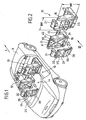
- Fig. 1 shows a motor vehicle 11 with an inventive, consisting of two individual seats 12, 13 seat assembly 10, the sake of clarity, the rear seat has been omitted.
- the viewer of Fig. 1 However, a rear seat 14 behind the two individual seats 12, 13 imagine, as for example the embodiment of Fig. 5 shows.
- Each individual seat 12, 13 has a seat surface part 15 and a backrest 16.
- the backrest 16 is formed by a seat back support structure 17, which is typically formed as a back frame 18, which has substantially the shape of an upside-down U.
- the back frame 18 is made in particular Fig. 3 can be seen and has two substantially vertically aligned, side rails 19a, 19b and a cross-beam 20, which connects the two upper ends of the spars together.
- the spars 19a, 19b are pivotable about a pivot axis 32 located in the lower connection region of the bar ends, which extends essentially transversely to the direction of travel X, and enable pivoting the backrest 16, which is lockable in different pivotal positions.
- spring elements that provide a certain elasticity of the backrest and upholstery, which in the Figures 1 and 2 however, are indicated.
- the cross-beam 20 is provided in its central region with corresponding receptacles and guides.
- a support member 24 is provided, which is formed separately from the back frame 18 and which, as best the FIGS. 3 and 4 make clear, a receiving device 23 for the support rods 22a, 22b of the headrest 21 and a mounting panel 26 for a functional unit 27 has.
- the receiving device 23 may be arranged for example on a power line component 25, which is formed for example as a cross member.
- the installation field 26 is arranged on the rear seat 33, which is the rear seat backrest 33, of the backrest 16, that is, the rear seat backrest 14.
- the support member 24 is formed in the embodiment according to all figures substantially plate-shaped and has a width B which corresponds substantially to the width BR of the backrest 16.
- the support member 24 also has a height H, which corresponds substantially to the height HR of the backrest 16.
- the height H of the support element 24 substantially corresponds to the length L of the spars 19a, 19b.
- fastening means 28 are provided, which are arranged on the support member side and counter-fastening means 29 which are arranged on the reclining frame side.
- the Figures 2 and 4 let recognize that the fastening means 28 and counter-fastening means 29 can be connected to each other along mounting directions by mutually aligned arrangement, so that the support element 24 can be attached to the backrest 16 from the back 34 of the back frame 18.
- the backrest 16 already largely prefabricate, such that the back frame 18 is provided with a Umpolsterung and the last assembly step, the attachment of the support member 24 is made on the back frame 18.
- connection elements may be provided on the support member 24, which allow a connection with supply lines, wherein the support element-side connection elements with backrest side, in particular reclining frame side mating connection elements can be brought into connection. If it should be necessary for a functional unit, such as a screen, to be supplied with power, the installation panel for the functional unit can already have corresponding connections, in particular plug connections, so that the functional unit only has to be plugged in.
- the connections in the installation field 26 of the support element 24 are supplied with the required operating voltage via a contact-element-side connection element, which is connected to a back-side mating connection element during assembly of the support element 24 to the back frame 18 with this.
- FIGS. 3 and 4 as well as the right single seat 13 in the Figures 1 and 2 show a pivotable about a pivot axis 31 tray 30, which has, for example, a cup or cup holder.
- the in each left individual seat 12 of Figures 1 and 2 indicated screen 35 represents another possible, a functional unit 27 forming component.
- the storage compartment 36 of each left individual seat 12 of Figures 1 and 2 is a functional unit within the meaning of the invention.
- the corresponding installation field 26 for the screen 35 or for the storage compartment 36 is within the meaning of the present patent application each located immediately behind the functional component 27, 35, 36 mounting surface of the support member 24.
- the installation panel 26 but equally a storage compartment or a fastening device for a Training functional unit.
- FIG. 5 also shows mirror elements, such as make-up mirrors, nets, the pocket-like recordings for storing magazines od. Like. form, are possible as shelves 37 and cup holder 38 trained functional units , In any case, the functional units 27 are those devices which offer a certain functionality for a user located in the rear seat.
- the cross-member 25 formed as a force component of the support member 24 may be formed much more stable than the cross-beam 20 of the back frame 18.
- the forces collected by the headrest 21 in the event of a crash are directly on the support rods 22a, 22b and the power line component 25 in introduced the spars 19a, 19b, so that a twist in the event of a crash can be avoided.
- the fastening elements 28 therefore serve for direct attachment to counter-fastening elements 29, which are arranged directly on the bars 19a, 19b or at least in the immediate vicinity of the spars. In this way, a force introduction of the forces occurring in the event of a crash can be done in a short way.
- the support member 24 may also function as a dazzle-like component which cover attachment areas of the padding, such as attachment areas 39 of the padding in the region of the backrest head 40 or mounting portions 41 of the padding in the region of the side cheeks of the backrest 16 such that the attachment of the padding on the back frame is simplified.
- the support element 24 can thus cover, as an optically terminating element, unsightly attachment areas 39, 41, thereby allowing a simplified attachment of the upholstery.
- the number of fasteners and mating fasteners 28, 29 is limited to four in the embodiment in the figures. In principle, however, a larger number of fasteners is possible, the point-like but equally may be formed like a strip.
- the backrest head 40 of the backrest 16 can be made significantly more stable, but it can also be an increase in the torsional stiffness of the backrest 16 can be achieved overall.
- the power line component 25 may also extend over the entire height H of the support element 24. In the event that the support element 24 is designed to be stable, it may be possible to dispense with the transverse members 20 of the back frame 18 required in the prior art.
- the support member may for example consist of plastic, wherein different components of the support element 24 may also consist of different materials. It is also advantageous that the support element 24 can form regions of the rear wall of the backrest 16, which provide an immediate outer end surface of the backrest 16. Alternatively, it is of course also possible that the support member 24 is provided on its back 33 with a padding.
Abstract
Description
Die Erfindung betrifft eine Sitzanordnung für Fahrzeuge gemäß Anspruch 1.The invention relates to a seat arrangement for vehicles according to claim 1.
Bei solchen Sitzanordnungen sind typischerweise die beiden vorderen Fahrzeugsitze einer Pkw-Limousine als Einzelsitz jeweils von einer mit einer Polsterung versehenen Sitzlehnentragstruktur in Form eines Lehnenrahmens gebildet. Der Lehnenrahmen ist dabei nach Art eines auf dem Kopf stehenden U ausgebildet und weist typischerweise zwei im wesentlichen vertikal ausgerichtete, in Fahrzeugquerrichtung voneinander beabstandete Holme auf, die an ihrem oberen, freien Ende durch eine Quertraverse miteinander verbunden sind. Die beiden Holme sind um eine in Fahrzeugquerrichtung verlaufende, am unteren Ende der Holme angeordnete Achse schwenkbar und in mehreren Schwenklagen arretierbar.In such seating arrangements, the two front vehicle seats of a passenger limousine are typically formed as a single seat in each case by a seat back support structure provided with a padding in the form of a backrest frame. The back frame is designed in the manner of an upside-down U and typically has two substantially vertically oriented, spaced apart in the vehicle transverse direction spars, which are connected to each other at its upper, free end by a cross-beam. The two spars are pivotable about an axis extending in the vehicle transverse direction, arranged at the lower end of the spars axis and lockable in several pivotal positions.
Der Lehnenrahmen ist darüber hinaus herkömmlich mit einer Vielzahl von Federelementen versehen, die die zur Erreichung des gewünschten Sitzkomforts erforderliche Elastizität bereitstellen.The back frame is also conventionally provided with a plurality of spring elements that provide the necessary to achieve the desired seating comfort elasticity.
Zur Befestigung der Kopfstütze an der Rückenlehne des vorderen Sitzes weist die Kopfstütze üblicherweise zwei Tragstangen auf, die in einer lehnenrahmenseitigen Aufnahmeeinrichtung gehalten sind. Hierzu ist in der oberen Quertraverse des Lehnenrahmens eine Führung vorgesehen, derart, dass die beiden Tragstangen die obere Quertraverse des Lehnenrahmens im wesentlichen vertikal durchstecken.To attach the headrest to the backrest of the front seat, the headrest usually has two support rods, which are held in a reclining frame side receiving device. For this purpose, a guide is provided in the upper cross-beam of the back frame, such that the two support rods push through the upper cross-beam of the backrest frame substantially vertically.
Typischerweise werden Kopfstützen von anderen Unternehmen gefertigt, als die Rückenlehnen des Fahrzeugsitzes, so dass es hinsichtlich der konstruktiven Anbindung der Kopfstütze an eine Sitzlehne sowie hinsichtlich deren Montage einer Vielzahl von Absprachen zwischen dem Kopfstützenhersteller und dem Sitzhersteller bedarf. Als problematisch stellt sich in diesem Zusammenhang dar, dass der für den Einbau der Aufnahmeeinrichtung für die Kopfstütze an dem Lehnenrahmen vorhandene Einbauraum nur sehr klein ist. Eine optimale Anpassung der Kopfstütze an die Rückenlehne, insbesondere hinsichtlich ihrer Klapperfreiheit in Gebrauch und hinsichtlich einer genauen Maßhaltigkeit für eine ordnungsgemäße Verstellung, ist nur in begrenztem Maße erreichbar.Typically, headrests are made by companies other than the seat backs of the vehicle seat, so in terms of the constructive connection of the headrest to a seat back and in terms of their assembly a variety of agreements between the headrest manufacturer and the seat manufacturer needs. A problem in this context is that the installation space available for the installation of the receiving device for the headrest on the back frame is very small. An optimal adaptation of the headrest to the backrest, in particular with regard to their rattle in use and in terms of an accurate dimensional stability for proper adjustment is achievable only to a limited extent.
Die beiden Tragstangen der Kopfstütze sind häufig einander eng benachbart angeordnet. Selbst dann, wenn die beiden Tragstangen an den äußeren Randbereichen der Kopfstütze befestigt werden, befinden sich die Anbindungsstellen der Tragstangen an die Quertraverse relativ nahe im Bereich der Mitte der Quertraverse. Die Quertraverse des Lehnenrahmens ist jedoch oft sehr dünn ausgebildet, so dass es im Crashfalle, bei dem auf die Kopfstütze sehr große Kräfte ausgeübt werden können, zu einer Verwindung der Quertraverse und einer damit einhergehenden Gefahr von Verletzungen kommen kann.The two support rods of the headrest are often arranged closely adjacent each other. Even if the two support rods are attached to the outer edge regions of the headrest, the attachment points of the support rods are located on the cross-beam relatively close to the center of the cross-beam. However, the crossbeam of the back frame is often designed to be very thin, so that it can come in a crash, in which can be exercised on the headrest very large forces, to a twisting of the crossbeam and an associated risk of injury.
Bei Sitzanordnungen des Standes der Technik spielt schließlich auch die Anbringung einer Funktionseinheit an der Rückseite der Rückenlehne des vorderen Sitzes eine besondere Rolle. So können Bildschirme für Video- oder DVD-Geräte, Computer einschließlich Bildschirm und Tastatur, Tassenhalter (cup holder) etc. vorgesehen werden. Die Anbringung einer derartigen Funktionseinheit an der Rückenlehne des vorderen Sitzes ist dabei mit einem hohen baulichen Aufwand verbunden.Finally, with seat assemblies of the prior art, the attachment of a functional unit to the back of the backrest of the front seat also plays a special role. Thus, screens can be provided for video or DVD devices, computers including screen and keyboard, cup holders, etc. The attachment of such a functional unit to the backrest of the front seat is associated with a high structural complexity.
So ist es beispielsweise aus der
Aus der
Aus der
Ausgehend von diesem Stand der Technik liegt die Aufgabe der Erfindung darin, die Sitzanordnung derart weiterzubilden, dass bei einfacher Bauweise eine verbesserte Anbringung der Kopfstütze an dem Lehnenrahmen und der Funktionseinheit an der Rückenlehne möglich wird.Based on this prior art, the object of the invention is to develop the seat assembly such that with a simple design, an improved attachment of the headrest on the back frame and the functional unit on the backrest is possible.
Die Erfindung löst diese Aufgabe mit den Merkmalen des Anspruches 1.The invention solves this problem with the features of claim 1.
Das Prinzip der Erfindung besteht somit im wesentlichen darin, die Kopfstütze und ein Einbaufeld für die Funktionseinheit zu einer gemeinsamen Baueinheit zusammenzufassen, die insgesamt an dem Lehnenrahmen befestigt wird. Die als Tragelement ausgebildete Baueinheit umfasst darüber hinaus ein Kraftleitungsbauteil, welches die im Crashfall auf die Kopfstütze ausgeübten Kräfte unmittelbar in die Rahmenstruktur des Lehnenrahmens einleitet. Hierzu kann das Kraftleitungsbauteil in hohem Maße verwindungssteif ausgebildet sein, und daher beispielsweise einen gegenüber dem Querschnitt herkömmlicher Quertraversen von Lehnenrahmen deutlich vergrößerten Querschnitt beziehungsweise eine stabilere Bauweise besitzen.The principle of the invention thus consists essentially in the headrest and a mounting panel for the functional unit to a to summarize common structural unit, which is attached to the entire backrest frame. The structural unit designed as a supporting element furthermore comprises a power-line component which directly introduces the forces exerted on the headrest in the event of a crash into the frame structure of the backrest frame. For this purpose, the power line component can be designed to be highly torsion-resistant, and therefore, for example, have a cross section that is significantly larger than the cross section of conventional transverse members of backrest frames or a more stable construction.
Vorteilhaft überbrückt das Tragelement den Abstand zwischen den beiden Holmen im Wesentlichen.Advantageously, the support element bridges the distance between the two beams substantially.
Insgesamt können in konstruktiver Hinsicht das Tragelement, die Kopfstütze und die Funktionseinheit z.B. bezüglich Kraftweiterleitung aufeinander optimal angepasst werden, da die gesamte Baueinheit an dem Lehnenrahmen befestigt wird. Es entfällt somit eine aufwendige Montage der Einzelteile vor Ort, wobei die Möglichkeit besteht, die Aufnahmeeinrichtung nahezu beliebig zu dimensionieren. Der beim Stand der Technik nur äußerst kleine Einbauraum für die Aufnahmeeinrichtung, der durch die Dimensionen der Quertraverse begrenzt war, ist nunmehr deutlich vergrößert.Overall, the structural element, the headrest and the functional unit can be structurally modified, e.g. be optimally adapted to each other in terms of force transmission, since the entire unit is attached to the back frame. It thus eliminates a complex assembly of items on site, with the possibility of dimensioning the receiving device almost arbitrarily. The in the prior art only extremely small installation space for the receiving device, which was limited by the dimensions of the cross-beam, is now significantly increased.
Da insbesondere für die Relativverstellung der Kopfstütze zu dem feststehenden Lehnenrahmen eine besondere Führung für eine Verlagerbarkeit der Tragstangen, beispielsweise durch entsprechende Führungshülsen, erforderlich ist, können die für die Höhenverstellung vorgesehenen Bauteile mit den erforderlichen geringen Toleranzen und höheren Maßhaltigkeiten gefertigt und entsprechend zusammengesetzt werden, wobei ein optimiertes Zusammenspiel der einzelnen Bauteile zueinander möglich wird.Since, in particular for the relative adjustment of the headrest to the fixed backrest frame a special guide for a displacement of the support rods, for example by appropriate guide sleeves, is required, provided for the height adjustment components can be manufactured with the required low tolerances and higher dimensional accuracy and assembled accordingly an optimized interaction of the individual components to each other is possible.
Außerdem besteht die Möglichkeit, die für eine Höhenverstellung erforderlichen Bauelemente, beispielsweise eine Vorrichtung zur elektrischen Höhenverstellung der Kopfstütze, auf einfachere Weise an dem Tragelement zu montieren, als dies bei Lehnenrahmen des Standes der Technik der Fall war. Dort mussten die für eine Höhenverstellung der Kopfstütze erforderlichen Bauteile in einen nur sehr eng begrenzten Einbauraum eingesetzt werden, der durch die beiden Holme des Lehnenrahmens seitlich begrenzt war, was zu einer umständlichen Montage führte.In addition, there is the possibility of required for a height adjustment components, such as a device for electrical height adjustment of the headrest, in a simpler manner to mount on the support element, as was the case with backrest frame of the prior art. There, the required for a height adjustment of the headrest components had to be used in a very limited installation space, which was laterally bounded by the two spars of the back frame, resulting in a cumbersome assembly.
Da erfindungsgemäß die Aufnahmeeinrichtung für die Kopfstütze an dem gesonderten Tragelement befestigt ist, kann eine vorteilhafte Baugruppen-Vormontage unter besserer Zugänglichkeit eines Befestigungssockels für die Aufnahmeeinrichtung erfolgen.Since the receiving device for the headrest according to the invention is attached to the separate support element, an advantageous assembly pre-assembly can be carried out with better accessibility of a mounting base for the receiving device.
Die erfindungsgemäße Lösung bietet darüber hinaus die Möglichkeit einer besseren Krafteinleitung der im Crashfalle auf die Kopfstütze ausgeübten Kräfte in die Rahmenstruktur des Lehnenrahmens, da das Tragelement unmittelbar an den beiden Holmen des Lehnenrahmens oder zumindest in unmittelbarer Nähe der Holme befestigt werden kann, so dass eine unmittelbare Kraftweiterleitung möglich wird. So können bei entsprechender Ausgestaltung des Tragelementes beziehungsweise eines an dem Tragelement angeordneten Kraftleitungsbauteils auch große Kräfte weitergeleitet werden.The solution according to the invention also offers the possibility of a better force introduction of the forces exerted on the headrest in the event of a crash forces in the frame structure of the back frame, since the support element can be attached directly to the two bars of the back frame or at least in the immediate vicinity of the spars, so that an immediate Force transmission is possible. Thus, with appropriate design of the support element or of a arranged on the support member power line component and large forces can be forwarded.
Schließlich ermöglicht die erfindungsgemäße Sitzanordnung auch einen einfachen Austausch der Funktionseinheit, der Kopfstütze und des Tragelementes, so dass von einer Modulbauweise gesprochen werden kann. Eine solche Modulbauweise erleichtert auch eine Austauschbarkeit eines montierten Tragelementes, beispielsweise für den Fall, dass ein Benutzer eine andere Funktionseinheit wünscht oder wenn im Schadensfalle wesentliche Bauelemente ausgetauscht werden müssen. Das Tragelement kann hierzu mit besonders einfach ausgestalteten Befestigungsmitteln versehen sein, sowie außerdem Anschlusselemente für Versorgungsleitungen aufweisen, die mit lehnenseitigen Gegenanschlusselementen verbunden werden können.Finally, the seat assembly according to the invention also allows easy replacement of the functional unit, the headrest and the support element, so that can be spoken of a modular design. Such a modular design also facilitates interchangeability of a mounted support element, for example, in the event that a user desires another functional unit or if essential components must be replaced in the event of damage. The support member may be provided for this purpose with particularly simple designed fasteners, as well as Having connection elements for supply lines, which can be connected to the back-side mating connection elements.
Aus der
Aus der
Aus der nicht gattungsgemäßen
Aus der
Aus der
Aus der
Aus der
Aus der
Aus der
Gemäß einer vorteilhaften Ausgestaltung der Erfindung erstreckt sich das Tragelement im Wesentlichen über die gesamte Breite und/oder im Wesentlichen über die gesamte Höhe der Rückseite der Rückenlehne. Bei dieser Ausgestaltung der Erfindung besteht ein wesentlicher Vorteil darin, dass das Tragelement im Wesentlichen die Rückwand der Rückenlehne ausbilden kann. So kann beispielsweise vorgesehen sein, dass das Tragelement an einer bereits umpolsterten Sitzlehnentragstruktur von deren Rückseite her befestigt wird, wobei dieser Befestigungsschritt der letzte Montageschritt der Rückenlehne ist.According to an advantageous embodiment of the invention, the support element extends substantially over the entire width and / or substantially over the entire height of the back of the backrest. In this embodiment of the invention, a significant advantage is that the support element can form substantially the rear wall of the backrest. For example, it may be provided that the support element is fastened to an already upholstered seat back support structure from the rear thereof, wherein this attachment step is the last assembly step of the backrest.
Die Formulierung, wonach sich das Tragelement im Wesentlichen über die gesamte Breite oder im wesentlichen über die gesamte Höhe der Rückseite der Rückenlehne erstreckt, soll dabei jedoch auch solche Ausführungsformen mit einschließen, bei denen nur ein wesentlicher Teil der Rückseite der Rückenlehne von dem Tragelement überspannt wird.However, the wording according to which the support element extends substantially over the entire width or substantially over the entire height of the rear side of the backrest should also include embodiments in which only a substantial part of the rear side of the backrest is covered by the support element ,
Die Erfindung lässt dabei auch die Möglichkeit offen, dass das Tragelement auf seiner zu dem hinteren Fahrzeugsitz hingewandten Seite kaschiert ist, beispielsweise mit einem Bezugsstoff oder mit Leder überzogen ist oder gegebenenfalls auch eine Polsterung aufweist.The invention also leaves open the possibility that the support element is laminated on its side facing the rear vehicle seat, for example, with a fabric or covered with leather or possibly also has a padding.
Gleichermaßen umfasst die Erfindung auch solche Tragelemente, die zumindest einen Bereich des Lehnenkopfes bilden.Likewise, the invention also includes such support elements that form at least a portion of the backrest head.
Möglich wird mit der erfindungsgemäßen Lösung auch eine Ausbildung des Tragelementes derart, dass dieses nach Art einer Abschlussschale die Rückseite der Rückenlehne ausbildet. Die dem hinteren Fahrzeugsitz zugewandte Rückwand der Rückenlehne wird dabei im wesentlichen von dem Tragelement gebildet.It is possible with the solution according to the invention also an embodiment of the support element such that it forms the back of the backrest in the manner of a closure shell. The rear vehicle seat facing the rear wall of the backrest is substantially formed by the support member.
Gemäß einer weiteren vorteilhaften Ausgestaltung der Erfindung ist die Kopfstütze mittels der wenigstens einen Tragstange lösbar in der Aufnahmeeinrichtung gehaltert. Vorzugsweise ist die Kopfstütze mittels zweier, in Fahrzeugquerrichtung voneinander beabstandeter Tragstangen in der Aufnahmeeinrichtung gehalten. Die einfache Lösbarkeit der Kopfstütze, insbesondere derart, dass die Tragstangen aus der Aufnahmeeinrichtung vollständig entnehmbar sind, ist von besonderer Bedeutung, um beispielsweise an der Kopfstütze einen Schonbezug anbringen zu können oder um bei Bedarf die Kopfstütze aus sonstigen Gründen auf einfache Weise lösen zu können.According to a further advantageous embodiment of the invention, the headrest is releasably supported by means of at least one support rod in the receiving device. Preferably, the headrest is held in the receiving device by means of two support rods spaced apart in the vehicle transverse direction. The easy solubility of the headrest, in particular such that the support rods from the receiving device are completely removable, is of particular importance, for example, to attach a protective cover to the headrest or to solve the headrest for other reasons in a simple manner if necessary.
Gemäß einer weiteren vorteilhaften Ausgestaltung der Erfindung ist an dem Tragelement ein mit der Kopfstütze zusammenwirkendes Steuerelement angeordnet. Ein derartiges Steuerelement kann beispielsweise eine Vorrichtung zur elektrischen Höhenverstellung, eine Vorrichtung zur crashaktiven Kopfstützensteuerung oder zur Auslösung von Kopfstützen-Airbags etc. sein. Das Tragelement bietet daher die Möglichkeit, derartige Steuerelemente unmittelbar an der aus Tragelement, Aufnahmeeinrichtung und Einbaufeld bestehenden Baueinheit anzuordnen, so dass eine weiter verbesserte Montage, beispielsweise aufgrund verbesserter Zugänglichkeit, möglich wird.According to a further advantageous embodiment of the invention, a co-operating with the headrest control is arranged on the support element. Such a control, for example, a device for electrical height adjustment, a device for crash-active headrest control or to trigger headrest airbags, etc. be. The support element offers Therefore, the possibility to arrange such controls directly to the existing support element, receiving device and mounting panel assembly, so that a further improved assembly, for example, due to improved accessibility is possible.
Gemäß einer weiteren vorteilhaften Ausgestaltung der Erfindung ist das Tragelement zur Befestigung an der Sitzlehnentragstruktur von der Rückseite der Sitzlehnentragstruktur her an diese ansetzbar, insbesondere an dieser befestigbar. Diese Ausgestaltung der Erfindung ermöglicht eine besonders einfache Montage des Tragelementes an der Sitzlehnentragstruktur derart, dass dieser Befestigungsschritt den letzten Montageschritt zur Fertigstellung der Sitzanordnung darstellt.According to a further advantageous embodiment of the invention, the support member for attaching to the seat back support structure from the back of the seat back support structure forth on this can be attached, in particular attachable to this. This embodiment of the invention enables a particularly simple mounting of the support element on the seat back support structure such that this attachment step represents the last assembly step for the completion of the seat assembly.
Möglich wird dabei außerdem eine vereinfachte beziehungsweise verbesserte Umpolsterung der Sitzlehnentragstruktur derart, dass das Tragelement eine vollständige Umpolsterung der Sitzlehnentragstruktur entbehrlich macht und gewisse Polsterungsbereiche nach Art einer Blende überdecken kann.What is also possible here is a simplified or improved padding of the seat back support structure in such a way that the support element eliminates the need for complete upholstery of the seat back support structure and can cover certain padding areas in the manner of a panel.
Gemäß einer weiteren vorteilhaften Ausgestaltung der Erfindung ist das Tragelement an dem Lehnenrahmen mittels Befestigungselementen befestigbar, die mit lehnenrahmenseitigen, in unmittelbarer Nähe der Holme oder an den Holmen angeordneten Gegenbefestigungselementen zusammenwirken. Durch Anordnung von Befestigungselementen und Gegenbefestigungselementen kann eine besonders einfache Verriegelung des Tragelementes an dem Lehnenrahmen erfolgen. Beispielsweise können auch Steckverbindungen, Rastverbindungen oder vergleichbare, das Tragelement mit dem Lehnenrahmen verriegelnde Verbindungen vorgesehen werden, die eine sichere Befestigung des Tragelementes an der Sitzlehnentragstruktur ermöglichen. Außerdem ermöglichen derartige Befestigungselemente eine besonders einfache Montage des Tragelementes an der Sitzlehnentragstruktur.According to a further advantageous embodiment of the invention, the support member to the back frame by means of fastening elements can be fastened, which cooperate with reclining frame side, arranged in the immediate vicinity of the spars or on the spars counter-fastening elements. By arranging fastening elements and counter-fastening elements, a particularly simple locking of the support element to the backrest frame can take place. For example, it is also possible to provide plug-in connections, snap-in connections or comparable connections which lock the support element to the backrest frame, which connections allow secure fastening of the support element to the seat back support structure. In addition, allow such fasteners a particularly simple mounting of the support element to the seat back support structure.
Gemäß einer weiteren vorteilhaften Ausgestaltung der Erfindung ist das Tragelement im wesentlichen plattenförmig ausgebildet. Eine derartige Ausgestaltung begünstigt die Ausbildung einer Rückwand der Sitzlehne durch das Tragelement.According to a further advantageous embodiment of the invention, the support element is formed substantially plate-shaped. Such a configuration favors the formation of a rear wall of the seat back by the support element.
Gemäß einer weiteren vorteilhaften Ausgestaltung der Erfindung weist das Tragelement Anschlusselemente für Versorgungsleitungen, z.B. Spannungsversorgungsleitungen, Signal- oder Datenleitungen, Pneumatik- oder Unterdruckleitungen auf, die mit lehnenseitigen Gegenanschlusselementen in Verbindung, z.B. in Steckverbindung gebracht werden können. Auf diese Weise können vordefinierte Anschlussstellen bereitgestellt werden, die die Funktionseinheit oder beispielsweise ein mit der Kopfstütze zusammenwirkendes Steuerelement mit der notwendigen Betriebsspannung oder mit einer erforderlichen Signalleitung oder einer Unterdruckleitung verbinden können.According to a further advantageous embodiment of the invention, the support element has connection elements for supply lines, e.g. Power supply lines, signal or data lines, pneumatic or vacuum lines connected to lean-side mating connection elements, e.g. can be brought into plug connection. In this way, predefined connection points can be provided, which can connect the functional unit or, for example, a headrest cooperating control with the necessary operating voltage or with a required signal line or a vacuum line.
Weitere Vorteile der Erfindung ergeben sich aus den nicht zitierten Unteransprüchen sowie anhand der in den Zeichnungen dargestellten und nachfolgend beschriebenen Ausführungsbeispiele. Darin zeigen:
- Fig. 1
- schematisch in Ansicht ein Personenkraftfahrzeug mit einer erfindungsgemäßen Sitzanordnung,
- Fig. 2
- die aus zwei vorderen Einzelsitzen bestehende Sitzanordnung der
Fig. 1 in Einzeldarstellung, - Fig. 3
- in schematischer, teilgeschnittener Ansicht etwa gemäß Ansichtspfeil III in
Fig. 2 den inFig. 2 rechten der beiden Fahrgastsitze in Rückansicht, - Fig. 4
- in einer schematischen Explosionsseitenansicht das Ausführungsbeispiel der
Fig. 3 gemäß Ansichtspfeil IV, und - Fig. 5
- in einer schematischen Darstellung etwa gemäß
Fig. 1 ein Kraftfahrzeug mit einem zweiten Ausführungsbeispiel der erfindungsgemäßen Sitzanordnung.
- Fig. 1
- schematically in view of a passenger vehicle with a seat arrangement according to the invention,
- Fig. 2
- consisting of two front individual seats seating arrangement of
Fig. 1 in individual presentation, - Fig. 3
- in a schematic, partially sectioned view approximately according to arrow III in
Fig. 2 the inFig. 2 right of the two passenger seats in rear view, - Fig. 4
- in a schematic exploded side view of the embodiment of
Fig. 3 according to arrow IV, and - Fig. 5
- in a schematic representation approximately according to
Fig. 1 a motor vehicle with a second embodiment of the seat assembly according to the invention.
In den Figuren ist die erfindungsgemäße Sitzanordnung in ihrer Gesamtheit mit 10 bezeichnet.In the figures, the seat assembly according to the invention is designated in its entirety by 10.
Jeder Einzelsitz 12, 13 weist ein Sitzflächenteil 15 und eine Rückenlehne 16 auf. Die Rückenlehne 16 wird dabei von einer Sitzlehnentragstruktur 17 gebildet, die typischerweise als Lehnenrahmen 18 ausgebildet ist, der im wesentlichen die Form eines auf dem Kopf stehenden U aufweist. Der Lehnenrahmen 18 ist insbesondere aus
Zur Befestigung einer Kopfstütze 21, die typischerweise zwei Tragstangen 22a und 22b aufweist, an der Rückenlehne 16 wird beim Stand der Technik die Quertraverse 20 in ihrem Mittenbereich mit entsprechenden Aufnahmen und Führungen versehen.For fixing a
Erfindungsgemäß ist ein Tragelement 24 vorgesehen, welches von dem Lehnenrahmen 18 gesondert ausgebildet ist und welches, wie dies am besten die
Das Tragelement 24 ist beim Ausführungsbeispiel gemäß allen Figuren im wesentlichen plattenförmig ausgebildet und weist eine Breite B auf, die im wesentlichen der Breite BR der Rückenlehne 16 entspricht. Das Tragelement 24 weist darüber hinaus eine Höhe H auf, die im wesentlichen der Höhe HR der Rückenlehne 16 entspricht. Insbesondere entspricht die Höhe H des Tragelementes 24 im wesentlichen der Länge L der Holme 19a, 19b.The
Zur Befestigung des Tragelementes 24 an der Sitzlehnentragstruktur 17 sind Befestigungsmittel 28 vorgesehen, die tragelementseitig angeordnet sind und Gegenbefestigungsmittel 29, die lehnenrahmenseitig angeordnet sind. Die
Darüber hinaus können nicht dargestellte Anschlusselemente an dem Tragelement 24 vorgesehen sein, die eine Verbindung mit Versorgungsleitungen ermöglichen, wobei die tragelementseitigen Anschlusselemente mit rückenlehnenseitigen, insbesondere lehnenrahmenseitigen Gegenanschlusselementen in Verbindung gebracht werden können. Falls erforderlich sein sollte, dass eine Funktionseinheit, wie beispielsweise ein Bildschirm, mit Strom versorgt werden soll, kann das Einbaufeld für die Funktionseinheit bereits entsprechende Anschlüsse, insbesondere Steckanschlüsse aufweisen, so dass die Funktionseinheit nur noch eingestöpselt werden muss. Die Anschlüsse in dem Einbaufeld 26 des Tragelementes 24 werden mit der erforderlichen Betriebsspannung über ein tragelementseitiges Anschlusselement versorgt, welches mit einem lehnenseitigen Gegenanschlusselement bei der Montage des Tragelementes 24 an dem Lehnenrahmen 18 mit diesem verbunden wird.In addition, not shown connection elements may be provided on the
Als Funktionseinheiten 27 kommen unterschiedliche Vorrichtungen in Betracht. Die
Ein Ausführungsbeispiel der
Aus den
Das Tragelement 24 kann darüber hinaus als blendenartiges Bauteil fungieren, welches Befestigungsbereiche der Polsterung, beispielsweise Befestigungsbereiche 39 der Polsterung im Bereich des Lehnenkopfes 40 oder Befestigungsbereiche 41 der Polsterung im Bereich der Seitenwangen der Rückenlehne 16 blendenartig überdecken, so dass die Befestigung der Polsterung an dem Lehnenrahmen vereinfacht ist. Das Tragelement 24 kann auf diese Weise als in optischer Hinsicht abschließendes Element unansehnliche Befestigungsbereiche 39, 41 überdecken, wodurch eine vereinfachte Befestigung der Polsterung möglich wird.The
Die Zahl der Befestigungselemente und Gegenbefestigungselemente 28, 29 ist bei dem Ausführungsbeispiel in den Figuren auf vier begrenzt. Grundsätzlich ist jedoch auch eine größere Zahl der Befestigungselemente möglich, die punktartig aber gleichermaßen auch leistenartig ausgebildet sein können.The number of fasteners and
Je nach Ausbildung des Tragelementes 24 kann nicht nur der Lehnenkopf 40 der Rückenlehne 16 deutlich stabiler ausgebildet werden, sondern es kann auch eine Erhöhung der Verwindungssteifigkeit der Rückenlehne 16 insgesamt erreicht werden. Das Kraftleitungsbauteil 25 kann sich auch über die gesamte Höhe H des Tragelementes 24 erstrecken. Für den Fall, dass das Tragelement 24 entsprechend stabil ausgestaltet wird, kann auf die beim Stand der Technik erforderlichen Quertraversen 20 des Lehnenrahmens 18 gegebenenfalls auch verzichtet werden.Depending on the design of the
Entscheidend ist, dass die aus Aufnahmeeinrichtung 23, Einbaufeld 26 und Tragelement 24 bestehende Baueinheit insgesamt vormontiert werden kann und als Baueinheit an der Sitzlehnentragstruktur 17 befestigbar ist.It is crucial that the assembly consisting of receiving
Das Tragelement kann beispielsweise aus Kunststoff bestehen, wobei verschiedene Bauelemente des Tragelementes 24 auch aus unterschiedlichen Materialien bestehen können. Vorteilhaft ist auch, dass das Tragelement 24 Bereiche der Rückwand der Rückenlehne 16 ausbilden kann, die eine unmittelbare äußere Abschlussfläche der Rückenlehne 16 bereitstellen. Alternativ ist es jedoch selbstverständlich auch möglich, dass das Tragelement 24 auf seiner Rückseite 33 mit einer Polsterung versehen ist.The support member may for example consist of plastic, wherein different components of the
Claims (14)
- Seat arrangement (10) for vehicles (11), in particular for a passenger car, comprising at least one front vehicle seat (12, 13), in particular an individual seat, and at least one rear vehicle seat (14), wherein the front vehicle seat for forming a backrest (16) comprises a seat-back support structure (17, 18) having two substantially vertically aligned bars, wherein a headrest (21) is fastened at least indirectly to the seat-back support structure, and wherein disposed on the rear (34) of the backrest (16) of the front vehicle seat, facing the rear vehicle seat, is a functional unit (27), such as a visual display unit, cup holder or the like, wherein a support element (24) that is separate from the seat-back support structure is provided, which is fastenable to the seat-back support structure, in particular to the rear (34) of the seat-back support structure (18), wherein a receiving element (23) for at least one support rod (22a, 22b) of the headrest is disposed on the support element, wherein the support element comprises a force transmission component in the form of a cross-bar, which introduces the forces arising in the event of a crash and exerted on the headrest into the bars, and wherein the support element (24) provides an installation compartment (26) for the functional unit.
- Seat arrangement according to claim 1, characterized in that the support element (24) extends substantially over the entire width (BR) and/or substantially over the entire height (HR) of the rear (33) of the backrest (16).
- Seat arrangement according to claim 1 or 2, characterized in that the headrest is mounted by means of the at least one support rod (22a, 22b) detachably in the receiving device (23).
- Seat arrangement according to one of the preceding claims, characterized in that disposed on the support element (24) is a control element that interacts with the headrest.
- Seat arrangement according to claim 4, characterized in that the control element comprises a device for height adjustment, in particular for electric height adjustment of the headrest.
- Seat arrangement according to one of the preceding claims, characterized in that the support element (24) for fastening to the seat-back support structure (17, 18) may be placed, in particular fastened, from the rear (34) of the seat-back support structure onto the seat-back structure.
- Seat arrangement according to one of the preceding claims, characterized in that the support element in its state of being fastened to the seat-back structure makes available a region of the rear wall of the backrest.
- Seat arrangement according to one of the preceding claims, characterized in that the seat-back support structure takes the form of a seat-back frame (18).
- Seat arrangement according to one of the preceding claims, characterized in that the two bars (19a, 19b) are pivotable about an axis (32) extending substantially transversely of the direction of travel of the vehicle and may be locked against pivoting in a plurality of operating positions.
- Seat arrangement according to claim 1, characterized in that the force transmission component is made of metal.
- Seat arrangement according to claim 1, characterized in that the force transmission component is designed so as to be to a large extent torsion-resistant.
- Seat arrangement according to one of claims 8 to 11, characterized in that the support element is fastenable to the seat-back frame by means of fastening elements (28) that interact with counterpart fastening elements (29) disposed on the seat back in the immediate vicinity of the bars or on the bars.
- Seat arrangement according to one of the preceding claims, characterized in that the support element (24) is of a substantially plate-shaped construction.
- Seat arrangement according to one of the preceding claims, characterized in that the support element has connection elements for supply lines, for example power supply lines, signal- or data lines, pneumatic or vacuum lines, which may be brought into connection, for example into plug-in connection, with mating connection elements on the seat back.
Applications Claiming Priority (2)
| Application Number | Priority Date | Filing Date | Title |
|---|---|---|---|
| DE10334595A DE10334595B4 (en) | 2003-07-28 | 2003-07-28 | Seat arrangement for vehicles |
| DE10334595 | 2003-07-28 |
Publications (3)
| Publication Number | Publication Date |
|---|---|
| EP1502810A2 EP1502810A2 (en) | 2005-02-02 |
| EP1502810A3 EP1502810A3 (en) | 2006-04-19 |
| EP1502810B1 true EP1502810B1 (en) | 2009-02-18 |
Family
ID=33521457
Family Applications (1)
| Application Number | Title | Priority Date | Filing Date |
|---|---|---|---|
| EP04017715A Not-in-force EP1502810B1 (en) | 2003-07-28 | 2004-07-27 | Vehicle seat arrangement |
Country Status (5)
| Country | Link |
|---|---|
| US (1) | US7896433B2 (en) |
| EP (1) | EP1502810B1 (en) |
| AT (1) | ATE423037T1 (en) |
| DE (2) | DE10334595B4 (en) |
| ES (1) | ES2322461T3 (en) |
Families Citing this family (27)
| Publication number | Priority date | Publication date | Assignee | Title |
|---|---|---|---|---|
| US20050161480A1 (en) * | 2004-01-23 | 2005-07-28 | Tirey Robert S. | Seat mounted storage unit for a motor vehicle |
| DE102005005654B4 (en) * | 2005-02-08 | 2018-02-15 | Recaro Aircraft Seating Gmbh & Co. Kg | System comprising a screen and control unit, and a seat |
| GB2424575B (en) * | 2005-04-01 | 2009-02-25 | Johnson Controls Automotive Uk | An anchor support for interchangeable modules |
| DE102005024904A1 (en) * | 2005-05-31 | 2006-12-07 | Volkswagen Ag | Beverage container retainer device for motor vehicle, has receptacle for intake of beverage container, and fastening unit designed such that device is able to be attached at two stanchions of head rest of motor vehicle seat |
| US20080238169A1 (en) * | 2007-03-30 | 2008-10-02 | Lear Corporation | Vehicle seat assembly having an accessory system and method of making the same |
| US20080252111A1 (en) * | 2007-04-13 | 2008-10-16 | Lear Corporation | Vehicle seat assembly having a modular accessory system and method of making the same |
| US8141948B2 (en) | 2007-05-11 | 2012-03-27 | Audiovox Corporation | Seat back entertainment system |
| DE102008030219A1 (en) | 2007-07-26 | 2009-01-29 | Bayerische Motoren Werke Aktiengesellschaft | Holder for holding article e.g. beverage bottle, has section movable between resting position and usage position, in which section is let away from component, so that article is held between component and section |
| US8274615B2 (en) * | 2008-03-07 | 2012-09-25 | Audiovox Corporation | Mobile video system |
| DE102010024715A1 (en) * | 2010-06-23 | 2011-12-29 | Volkswagen Ag | Backrest of a motor vehicle seat |
| WO2012078495A2 (en) * | 2010-12-07 | 2012-06-14 | Weber Aircraft Llc | Modular display assembly |
| DE102012022405A1 (en) * | 2012-11-16 | 2014-05-22 | Kamei Automotive Gmbh | Fixing system for fastening a storage box in a motor vehicle |
| TR201910601T4 (en) | 2012-12-21 | 2019-08-21 | Recaro Aircraft Seating Gmbh & Co Kg | Aircraft seat holding device. |
| DE102012112943A1 (en) * | 2012-12-21 | 2014-06-26 | Recaro Aircraft Seating Gmbh & Co. Kg | Aircraft seat carrier device |
| FR3010008B1 (en) * | 2013-09-02 | 2016-12-02 | Peugeot Citroen Automobiles Sa | BIPARTIE MODULAR HULL CLADDING DEVICE FOR A REAR FRONT OF A VEHICLE SEAT BACK |
| AU2015321417B2 (en) * | 2014-09-25 | 2020-01-16 | King Furniture Australia Pty Ltd | "an article of furniture" |
| DE102014220549A1 (en) | 2014-10-09 | 2016-04-14 | Volkswagen Aktiengesellschaft | Folding table and vehicle seat with such a folding table |
| WO2016089848A1 (en) * | 2014-12-04 | 2016-06-09 | B/E Aerospace, Inc. | Passenger seat with full seatback video display |
| US20170349105A1 (en) * | 2016-06-02 | 2017-12-07 | Platros LLC | Vehicular Caddy |
| US20180118122A1 (en) * | 2016-11-01 | 2018-05-03 | Ford Global Technologies, Llc | Seat assembly with integral security paperwork organizer |
| JP6533564B2 (en) * | 2017-10-24 | 2019-06-19 | 本田技研工業株式会社 | Headrest storage structure |
| US10758053B2 (en) | 2017-12-12 | 2020-09-01 | Bobachi, Llc | Screen |
| US10427611B2 (en) * | 2018-01-12 | 2019-10-01 | Ford Global Technologies, Llc | Storage for seating assembly |
| DE102018002611A1 (en) | 2018-03-29 | 2019-10-02 | Psa Automobiles Sa | Backrest for a vehicle seat, vehicle seat with the backrest and vehicle with the vehicle seat |
| US10894492B2 (en) * | 2019-03-26 | 2021-01-19 | Toyota Motor Engineering & Manufacturing North America, Inc | Vehicle seats providing access to child seat release latches |
| US11772799B2 (en) * | 2020-10-23 | 2023-10-03 | Adient Aerospace, Llc | Seatback for a vehicle seat |
| US11518313B1 (en) * | 2021-06-28 | 2022-12-06 | Aubrey Michael Gray | Carseat tray devices and methods |
Family Cites Families (37)
| Publication number | Priority date | Publication date | Assignee | Title |
|---|---|---|---|---|
| US2481943A (en) * | 1944-09-28 | 1949-09-13 | Pullman Standard Car Mfg Co | Seat and leg rest arrangement |
| US2566757A (en) * | 1948-03-19 | 1951-09-04 | Sylvia C Alexander | Headrest |
| US3253859A (en) * | 1964-03-20 | 1966-05-31 | Tom M Merriman | Safety pad |
| US3337268A (en) * | 1966-03-21 | 1967-08-22 | Earl H Belk | Headrest for vehicle seat |
| DE1680264A1 (en) * | 1967-09-19 | 1972-04-13 | Butz Eugen Otto | Head restraints designed especially for motor vehicle seats |
| DE1945571C3 (en) * | 1969-09-09 | 1978-07-20 | Butz, Eugen Otto, 4010 Hilden | Inclination adjustment device for headrests of vehicle seats |
| DE2034832C3 (en) * | 1970-07-14 | 1980-12-04 | Eugen Otto 4010 Hilden Butz | Headrest for vehicle seats |
| DE2718237A1 (en) | 1977-04-23 | 1978-11-02 | Eugen Otto Butz | Detachable headrest for car seat - has U=profile main support frame clipped over seat back and formed with metal insert frame in front |
| US4681366A (en) * | 1984-07-02 | 1987-07-21 | Irvin Industries, Inc. | Vanity mirror or vehicle accessory assembly and mounting apparatus therefor |
| DE3444802A1 (en) * | 1984-12-08 | 1986-06-12 | Messerschmitt-Bölkow-Blohm GmbH, 8012 Ottobrunn | METHOD AND ARRANGEMENT FOR CARRYING OUT PASSENGER-RELATED AND / OR PLANE-RELATED FUNCTIONS IN AN AIRPLANE |
| IT208138Z2 (en) * | 1985-08-09 | 1988-04-11 | S I C A M Societa Italiana Cus | VEHICLE SEAT |
| US4792183A (en) * | 1987-10-29 | 1988-12-20 | Townsend Iii William R | Desk for use in automobiles |
| DE4109497C1 (en) * | 1991-03-22 | 1992-08-13 | Mercedes-Benz Aktiengesellschaft, 7000 Stuttgart, De | |
| US5269229A (en) * | 1992-02-06 | 1993-12-14 | Niran Akapatangkul | Retractible tray assembly for use on a vehicle seat back |
| DE9205820U1 (en) * | 1992-04-30 | 1992-07-02 | Saxberger, Adolf, 8000 Muenchen, De | |
| US5275466A (en) * | 1992-09-01 | 1994-01-04 | Rentchler Jr John W | Portable armrest |
| DE4325996C2 (en) * | 1993-08-03 | 1998-05-28 | Brose Fahrzeugteile | Adjustment device for a motor-adjustable headrest of a motor vehicle |
| DE9407193U1 (en) * | 1994-05-05 | 1994-09-29 | Offen Rolf Dieter | Car seat |
| DE29504668U1 (en) * | 1995-03-18 | 1995-08-10 | Schroeder Detlef Dipl Ing | On-board desk for cars or the like |
| DE29516922U1 (en) * | 1995-10-26 | 1996-01-04 | Schroll Stefan | Footrest for child seats |
| DE19544267A1 (en) * | 1995-11-28 | 1997-06-05 | Roland Drignath | Clothes holder, etc., on vehicle furnishing |
| DE19546543B4 (en) * | 1995-12-13 | 2007-10-04 | Edag Engineering + Design Ag | To be attached to a tilt-adjustable backrest of a seat folding table |
| US5848661A (en) * | 1996-10-22 | 1998-12-15 | Lear Corporation | Vehicle seat assembly including at least one occupant sensing system and method of making same |
| US6105839A (en) * | 1997-11-25 | 2000-08-22 | Bell; Carolyn | Seatback carrier |
| US5927813A (en) * | 1998-02-05 | 1999-07-27 | Tachi-S Co., Ltd. | Arrangement of headrest stay holder and holder bracket in vehicles seat |
| DE19808404A1 (en) * | 1998-03-02 | 1999-09-09 | Butz Peter Verwaltung | Seat arrangement for vehicles with a module-like built-in part forming a mounting recess, such as a through-loading recess of a through-loading device or the like |
| US6216927B1 (en) * | 1998-08-03 | 2001-04-17 | Ronald Meritt | Mounting system for releasably and securely mounting an entertainment accessory within an automobile |
| US6199948B1 (en) * | 1998-12-16 | 2001-03-13 | Johnson Controls Technology Company | Interchangeable module system |
| US6109690A (en) * | 1998-12-18 | 2000-08-29 | Johnson Controls Technology Company | Pivoting seat back |
| DE19901073A1 (en) * | 1999-01-14 | 2000-07-27 | Daimler Chrysler Ag | Stowage container system for motor vehicle has container with adapter for attachment to internal vehicle component with holding elements for releasable connection to carrying elements |
| DE10029624A1 (en) * | 2000-06-20 | 2002-01-03 | Volkswagen Ag | Back rest and head rest arrangement for vehicle seat has frame construction with integral stowage compartment in rear part of back rest and/or head rest formed by profile struts in frame |
| US6994401B1 (en) * | 2000-09-14 | 2006-02-07 | Lear Corporation | Seat backrest cover module |
| US6655745B2 (en) * | 2001-08-23 | 2003-12-02 | H.O. Bostrom Company, Inc. | Emergency vehicle seat with integrated seat belt |
| US6607241B2 (en) * | 2001-08-23 | 2003-08-19 | Collins & Aikman Products Co. | Storage apparatus that attaches to a vehicle seat |
| US6502900B1 (en) * | 2001-09-27 | 2003-01-07 | Collins & Aikman Products Co. | Removable and vertically adjustable storage apparatus for vehicle seat backrest |
| US6629726B2 (en) * | 2001-09-27 | 2003-10-07 | Collins & Aikman Products Co. | Storage apparatus that attaches to a vehicle seat |
| US6830292B1 (en) * | 2004-01-09 | 2004-12-14 | Mitsuhiro Yoda | Table for a motor vehicle seat |
-
2003
- 2003-07-28 DE DE10334595A patent/DE10334595B4/en not_active Expired - Fee Related
-
2004
- 2004-07-27 ES ES04017715T patent/ES2322461T3/en active Active
- 2004-07-27 AT AT04017715T patent/ATE423037T1/en not_active IP Right Cessation
- 2004-07-27 US US10/900,064 patent/US7896433B2/en not_active Expired - Fee Related
- 2004-07-27 DE DE502004009000T patent/DE502004009000D1/en active Active
- 2004-07-27 EP EP04017715A patent/EP1502810B1/en not_active Not-in-force
Also Published As
| Publication number | Publication date |
|---|---|
| ES2322461T3 (en) | 2009-06-22 |
| DE10334595A1 (en) | 2005-03-03 |
| EP1502810A2 (en) | 2005-02-02 |
| DE502004009000D1 (en) | 2009-04-02 |
| US7896433B2 (en) | 2011-03-01 |
| EP1502810A3 (en) | 2006-04-19 |
| ATE423037T1 (en) | 2009-03-15 |
| DE10334595B4 (en) | 2006-03-16 |
| US20050110310A1 (en) | 2005-05-26 |
Similar Documents
| Publication | Publication Date | Title |
|---|---|---|
| EP1502810B1 (en) | Vehicle seat arrangement | |
| EP0407741B1 (en) | Head restraint for rear seats | |
| EP1717099B1 (en) | Headrest for vehicle seats | |
| EP3359416B1 (en) | Headrest of a vehicle seat | |
| EP0746219A1 (en) | Seatback with adjustable lordosis support for seats | |
| EP0940289B1 (en) | Vehicle seat arrangement with a modular insert which forms a holding opening such as a loading opening | |
| EP0846591A2 (en) | Detachable fastening of a child seat to a vehicle seat with tiltable backrest | |
| DE102016102310A1 (en) | VALUE ASSEMBLY FOR BACKREST AND UPHOLSTERY | |
| EP2583862B1 (en) | Vehicle seat, in particular rail vehicle seat, with an upholstery element fixing frame | |
| DE2113579A1 (en) | Device for fastening safety devices in a vehicle | |
| WO2010017856A1 (en) | Headrest receptacle | |
| DE10303619A1 (en) | Child's safety seat has belt guide on base section or support section for cross-extending lap strap, and upwards extending pivotable lever arm is installed on base section for deflection and tensioning of lap strap around belt guide | |
| EP0101073B1 (en) | Motor car with tiltable rear seat and adjustable head rests | |
| DE202008017568U1 (en) | Safety device for a child seat in a vehicle | |
| DE4126518C2 (en) | Vehicle seat | |
| DE102004008877A1 (en) | Airplane passenger seat row | |
| DE102008017711B4 (en) | Motor vehicle seat with a fastening means for fastening a child seat and seat assembly with such a motor vehicle seat | |
| DE20311668U1 (en) | Seat arrangement for vehicles has functional unit such as display screen attached to rear of front seat back rest, separate bearer element for attachment to rear of seat back bearer structure | |
| DE10038813A1 (en) | Car seat headrest with rod-guided movement uses cross axis in top and bottom guides parallel to supporting rods so headrest resting on seat back can flip round and over to rear | |
| DE19955294C2 (en) | Motor vehicle seat with seat depth adjustment | |
| EP2268543B1 (en) | Air passenger seat with a fastening device for fastening a child seat | |
| DE4128701A1 (en) | Sepn. of luggage space from passenger space in car - partition attached to backrest of rear seat and underside of roof | |
| AT506239B1 (en) | HEADREST AND SEAT WITH SUCH A HEADREST | |
| EP3798052A1 (en) | Vehicle seat support and vehicle seat | |
| DE19543349C1 (en) | Two-part windscreen for providing open-car front |
Legal Events
| Date | Code | Title | Description |
|---|---|---|---|
| PUAI | Public reference made under article 153(3) epc to a published international application that has entered the european phase |
Free format text: ORIGINAL CODE: 0009012 |
|
| AK | Designated contracting states |
Kind code of ref document: A2 Designated state(s): AT BE BG CH CY CZ DE DK EE ES FI FR GB GR HU IE IT LI LU MC NL PL PT RO SE SI SK TR |
|
| AX | Request for extension of the european patent |
Extension state: AL HR LT LV MK |
|
| PUAL | Search report despatched |
Free format text: ORIGINAL CODE: 0009013 |
|
| AK | Designated contracting states |
Kind code of ref document: A3 Designated state(s): AT BE BG CH CY CZ DE DK EE ES FI FR GB GR HU IE IT LI LU MC NL PL PT RO SE SI SK TR |
|
| AX | Request for extension of the european patent |
Extension state: AL HR LT LV MK |
|
| RIC1 | Information provided on ipc code assigned before grant |
Ipc: B60N 2/48 20060101ALI20060227BHEP Ipc: B60R 11/00 20060101ALI20060227BHEP Ipc: B60N 3/10 20060101ALI20060227BHEP Ipc: B60N 3/00 20060101AFI20041103BHEP Ipc: B60N 2/68 20060101ALI20060227BHEP |
|
| 17P | Request for examination filed |
Effective date: 20060405 |
|
| AKX | Designation fees paid |
Designated state(s): AT BE BG CH CY CZ DE DK EE ES FI FR GB GR HU IE IT LI LU MC NL PL PT RO SE SI SK TR |
|
| 17Q | First examination report despatched |
Effective date: 20070214 |
|
| RAP1 | Party data changed (applicant data changed or rights of an application transferred) |
Owner name: GRAMMER AG |
|
| REG | Reference to a national code |
Ref country code: SE Ref legal event code: TRGR |
|
| GRAP | Despatch of communication of intention to grant a patent |
Free format text: ORIGINAL CODE: EPIDOSNIGR1 |
|
| GRAS | Grant fee paid |
Free format text: ORIGINAL CODE: EPIDOSNIGR3 |
|
| GRAA | (expected) grant |
Free format text: ORIGINAL CODE: 0009210 |
|
| AK | Designated contracting states |
Kind code of ref document: B1 Designated state(s): AT BE BG CH CY CZ DE DK EE ES FI FR GB GR HU IE IT LI LU MC NL PL PT RO SE SI SK TR |
|
| REG | Reference to a national code |
Ref country code: GB Ref legal event code: FG4D Free format text: NOT ENGLISH |
|
| REG | Reference to a national code |
Ref country code: CH Ref legal event code: EP |
|
| REG | Reference to a national code |
Ref country code: IE Ref legal event code: FG4D Free format text: LANGUAGE OF EP DOCUMENT: GERMAN |
|
| REF | Corresponds to: |
Ref document number: 502004009000 Country of ref document: DE Date of ref document: 20090402 Kind code of ref document: P |
|
| REG | Reference to a national code |
Ref country code: ES Ref legal event code: FG2A Ref document number: 2322461 Country of ref document: ES Kind code of ref document: T3 |
|
| PG25 | Lapsed in a contracting state [announced via postgrant information from national office to epo] |
Ref country code: FI Free format text: LAPSE BECAUSE OF FAILURE TO SUBMIT A TRANSLATION OF THE DESCRIPTION OR TO PAY THE FEE WITHIN THE PRESCRIBED TIME-LIMIT Effective date: 20090218 Ref country code: SI Free format text: LAPSE BECAUSE OF FAILURE TO SUBMIT A TRANSLATION OF THE DESCRIPTION OR TO PAY THE FEE WITHIN THE PRESCRIBED TIME-LIMIT Effective date: 20090218 Ref country code: NL Free format text: LAPSE BECAUSE OF FAILURE TO SUBMIT A TRANSLATION OF THE DESCRIPTION OR TO PAY THE FEE WITHIN THE PRESCRIBED TIME-LIMIT Effective date: 20090218 |
|
| NLV1 | Nl: lapsed or annulled due to failure to fulfill the requirements of art. 29p and 29m of the patents act | ||
| PG25 | Lapsed in a contracting state [announced via postgrant information from national office to epo] |
Ref country code: PL Free format text: LAPSE BECAUSE OF FAILURE TO SUBMIT A TRANSLATION OF THE DESCRIPTION OR TO PAY THE FEE WITHIN THE PRESCRIBED TIME-LIMIT Effective date: 20090218 |
|
| REG | Reference to a national code |
Ref country code: IE Ref legal event code: FD4D |
|
| PG25 | Lapsed in a contracting state [announced via postgrant information from national office to epo] |
Ref country code: EE Free format text: LAPSE BECAUSE OF FAILURE TO SUBMIT A TRANSLATION OF THE DESCRIPTION OR TO PAY THE FEE WITHIN THE PRESCRIBED TIME-LIMIT Effective date: 20090218 Ref country code: DK Free format text: LAPSE BECAUSE OF FAILURE TO SUBMIT A TRANSLATION OF THE DESCRIPTION OR TO PAY THE FEE WITHIN THE PRESCRIBED TIME-LIMIT Effective date: 20090218 Ref country code: IE Free format text: LAPSE BECAUSE OF FAILURE TO SUBMIT A TRANSLATION OF THE DESCRIPTION OR TO PAY THE FEE WITHIN THE PRESCRIBED TIME-LIMIT Effective date: 20090218 Ref country code: PT Free format text: LAPSE BECAUSE OF FAILURE TO SUBMIT A TRANSLATION OF THE DESCRIPTION OR TO PAY THE FEE WITHIN THE PRESCRIBED TIME-LIMIT Effective date: 20090727 Ref country code: CZ Free format text: LAPSE BECAUSE OF FAILURE TO SUBMIT A TRANSLATION OF THE DESCRIPTION OR TO PAY THE FEE WITHIN THE PRESCRIBED TIME-LIMIT Effective date: 20090218 |
|
| PG25 | Lapsed in a contracting state [announced via postgrant information from national office to epo] |
Ref country code: RO Free format text: LAPSE BECAUSE OF FAILURE TO SUBMIT A TRANSLATION OF THE DESCRIPTION OR TO PAY THE FEE WITHIN THE PRESCRIBED TIME-LIMIT Effective date: 20090218 Ref country code: SK Free format text: LAPSE BECAUSE OF FAILURE TO SUBMIT A TRANSLATION OF THE DESCRIPTION OR TO PAY THE FEE WITHIN THE PRESCRIBED TIME-LIMIT Effective date: 20090218 |
|
| PLBE | No opposition filed within time limit |
Free format text: ORIGINAL CODE: 0009261 |
|
| STAA | Information on the status of an ep patent application or granted ep patent |
Free format text: STATUS: NO OPPOSITION FILED WITHIN TIME LIMIT |
|
| 26N | No opposition filed |
Effective date: 20091119 |
|
| PG25 | Lapsed in a contracting state [announced via postgrant information from national office to epo] |
Ref country code: BG Free format text: LAPSE BECAUSE OF FAILURE TO SUBMIT A TRANSLATION OF THE DESCRIPTION OR TO PAY THE FEE WITHIN THE PRESCRIBED TIME-LIMIT Effective date: 20090518 |
|
| BERE | Be: lapsed |
Owner name: GRAMMER A.G. Effective date: 20090731 |
|
| PG25 | Lapsed in a contracting state [announced via postgrant information from national office to epo] |
Ref country code: MC Free format text: LAPSE BECAUSE OF NON-PAYMENT OF DUE FEES Effective date: 20090731 |
|
| REG | Reference to a national code |
Ref country code: CH Ref legal event code: PL |
|
| PG25 | Lapsed in a contracting state [announced via postgrant information from national office to epo] |
Ref country code: CH Free format text: LAPSE BECAUSE OF NON-PAYMENT OF DUE FEES Effective date: 20090731 Ref country code: LI Free format text: LAPSE BECAUSE OF NON-PAYMENT OF DUE FEES Effective date: 20090731 |
|
| PG25 | Lapsed in a contracting state [announced via postgrant information from national office to epo] |
Ref country code: BE Free format text: LAPSE BECAUSE OF NON-PAYMENT OF DUE FEES Effective date: 20090731 |
|
| PG25 | Lapsed in a contracting state [announced via postgrant information from national office to epo] |
Ref country code: GR Free format text: LAPSE BECAUSE OF FAILURE TO SUBMIT A TRANSLATION OF THE DESCRIPTION OR TO PAY THE FEE WITHIN THE PRESCRIBED TIME-LIMIT Effective date: 20090519 |
|
| PG25 | Lapsed in a contracting state [announced via postgrant information from national office to epo] |
Ref country code: AT Free format text: LAPSE BECAUSE OF NON-PAYMENT OF DUE FEES Effective date: 20090727 |
|
| PG25 | Lapsed in a contracting state [announced via postgrant information from national office to epo] |
Ref country code: LU Free format text: LAPSE BECAUSE OF NON-PAYMENT OF DUE FEES Effective date: 20090727 |
|
| PG25 | Lapsed in a contracting state [announced via postgrant information from national office to epo] |
Ref country code: HU Free format text: LAPSE BECAUSE OF FAILURE TO SUBMIT A TRANSLATION OF THE DESCRIPTION OR TO PAY THE FEE WITHIN THE PRESCRIBED TIME-LIMIT Effective date: 20090819 |
|
| PG25 | Lapsed in a contracting state [announced via postgrant information from national office to epo] |
Ref country code: TR Free format text: LAPSE BECAUSE OF FAILURE TO SUBMIT A TRANSLATION OF THE DESCRIPTION OR TO PAY THE FEE WITHIN THE PRESCRIBED TIME-LIMIT Effective date: 20090218 |
|
| PG25 | Lapsed in a contracting state [announced via postgrant information from national office to epo] |
Ref country code: CY Free format text: LAPSE BECAUSE OF FAILURE TO SUBMIT A TRANSLATION OF THE DESCRIPTION OR TO PAY THE FEE WITHIN THE PRESCRIBED TIME-LIMIT Effective date: 20090218 |
|
| PGFP | Annual fee paid to national office [announced via postgrant information from national office to epo] |
Ref country code: GB Payment date: 20120716 Year of fee payment: 9 |
|
| PGFP | Annual fee paid to national office [announced via postgrant information from national office to epo] |
Ref country code: ES Payment date: 20120726 Year of fee payment: 9 |
|
| PGFP | Annual fee paid to national office [announced via postgrant information from national office to epo] |
Ref country code: SE Payment date: 20130726 Year of fee payment: 10 |
|
| GBPC | Gb: european patent ceased through non-payment of renewal fee |
Effective date: 20130727 |
|
| PG25 | Lapsed in a contracting state [announced via postgrant information from national office to epo] |
Ref country code: GB Free format text: LAPSE BECAUSE OF NON-PAYMENT OF DUE FEES Effective date: 20130727 |
|
| PGFP | Annual fee paid to national office [announced via postgrant information from national office to epo] |
Ref country code: DE Payment date: 20140730 Year of fee payment: 11 |
|
| PGFP | Annual fee paid to national office [announced via postgrant information from national office to epo] |
Ref country code: FR Payment date: 20140724 Year of fee payment: 11 |
|
| PGFP | Annual fee paid to national office [announced via postgrant information from national office to epo] |
Ref country code: IT Payment date: 20140728 Year of fee payment: 11 |
|
| REG | Reference to a national code |
Ref country code: SE Ref legal event code: EUG |
|
| PG25 | Lapsed in a contracting state [announced via postgrant information from national office to epo] |
Ref country code: SE Free format text: LAPSE BECAUSE OF NON-PAYMENT OF DUE FEES Effective date: 20140728 |
|
| REG | Reference to a national code |
Ref country code: ES Ref legal event code: FD2A Effective date: 20150709 |
|
| PG25 | Lapsed in a contracting state [announced via postgrant information from national office to epo] |
Ref country code: ES Free format text: LAPSE BECAUSE OF NON-PAYMENT OF DUE FEES Effective date: 20130728 |
|
| REG | Reference to a national code |
Ref country code: DE Ref legal event code: R119 Ref document number: 502004009000 Country of ref document: DE |
|
| PG25 | Lapsed in a contracting state [announced via postgrant information from national office to epo] |
Ref country code: IT Free format text: LAPSE BECAUSE OF NON-PAYMENT OF DUE FEES Effective date: 20150727 Ref country code: DE Free format text: LAPSE BECAUSE OF NON-PAYMENT OF DUE FEES Effective date: 20160202 |
|
| REG | Reference to a national code |
Ref country code: FR Ref legal event code: ST Effective date: 20160331 |
|
| PG25 | Lapsed in a contracting state [announced via postgrant information from national office to epo] |
Ref country code: FR Free format text: LAPSE BECAUSE OF NON-PAYMENT OF DUE FEES Effective date: 20150731 |