EP1502720A1 - Honeycomb forming die - Google Patents
Honeycomb forming die Download PDFInfo
- Publication number
- EP1502720A1 EP1502720A1 EP03745398A EP03745398A EP1502720A1 EP 1502720 A1 EP1502720 A1 EP 1502720A1 EP 03745398 A EP03745398 A EP 03745398A EP 03745398 A EP03745398 A EP 03745398A EP 1502720 A1 EP1502720 A1 EP 1502720A1
- Authority
- EP
- European Patent Office
- Prior art keywords
- die
- honeycomb body
- cell blocks
- forming
- extruded
- Prior art date
- Legal status (The legal status is an assumption and is not a legal conclusion. Google has not performed a legal analysis and makes no representation as to the accuracy of the status listed.)
- Granted
Links
- 229910052751 metal Inorganic materials 0.000 claims description 7
- 239000002184 metal Substances 0.000 claims description 7
- 238000005245 sintering Methods 0.000 claims description 7
- XEEYBQQBJWHFJM-UHFFFAOYSA-N Iron Chemical group [Fe] XEEYBQQBJWHFJM-UHFFFAOYSA-N 0.000 claims description 5
- 239000000843 powder Substances 0.000 claims description 5
- 239000011230 binding agent Substances 0.000 claims description 4
- 230000002093 peripheral effect Effects 0.000 claims description 4
- 229910052723 transition metal Inorganic materials 0.000 claims description 3
- 238000001125 extrusion Methods 0.000 abstract description 17
- 238000005452 bending Methods 0.000 abstract description 5
- 230000000052 comparative effect Effects 0.000 description 13
- 239000004927 clay Substances 0.000 description 9
- 238000000227 grinding Methods 0.000 description 4
- 239000000463 material Substances 0.000 description 3
- 239000002994 raw material Substances 0.000 description 3
- 229910009043 WC-Co Inorganic materials 0.000 description 2
- 239000006061 abrasive grain Substances 0.000 description 2
- 229910017052 cobalt Inorganic materials 0.000 description 2
- 239000010941 cobalt Substances 0.000 description 2
- GUTLYIVDDKVIGB-UHFFFAOYSA-N cobalt atom Chemical compound [Co] GUTLYIVDDKVIGB-UHFFFAOYSA-N 0.000 description 2
- 239000002131 composite material Substances 0.000 description 2
- 230000008602 contraction Effects 0.000 description 2
- 229910003460 diamond Inorganic materials 0.000 description 2
- 239000010432 diamond Substances 0.000 description 2
- 238000003754 machining Methods 0.000 description 2
- 239000013618 particulate matter Substances 0.000 description 2
- 238000005498 polishing Methods 0.000 description 2
- UONOETXJSWQNOL-UHFFFAOYSA-N tungsten carbide Chemical compound [W+]#[C-] UONOETXJSWQNOL-UHFFFAOYSA-N 0.000 description 2
- XUIMIQQOPSSXEZ-UHFFFAOYSA-N Silicon Chemical compound [Si] XUIMIQQOPSSXEZ-UHFFFAOYSA-N 0.000 description 1
- 239000010953 base metal Substances 0.000 description 1
- 239000000919 ceramic Substances 0.000 description 1
- 238000002485 combustion reaction Methods 0.000 description 1
- 230000007547 defect Effects 0.000 description 1
- 229910052742 iron Inorganic materials 0.000 description 1
- 238000004898 kneading Methods 0.000 description 1
- 238000004519 manufacturing process Methods 0.000 description 1
- 238000000034 method Methods 0.000 description 1
- 229910052759 nickel Inorganic materials 0.000 description 1
- 229910052710 silicon Inorganic materials 0.000 description 1
- 239000010703 silicon Substances 0.000 description 1
- 229910001220 stainless steel Inorganic materials 0.000 description 1
- 239000010935 stainless steel Substances 0.000 description 1
- XLYOFNOQVPJJNP-UHFFFAOYSA-N water Substances O XLYOFNOQVPJJNP-UHFFFAOYSA-N 0.000 description 1
Images



Classifications
-
- B—PERFORMING OPERATIONS; TRANSPORTING
- B28—WORKING CEMENT, CLAY, OR STONE
- B28B—SHAPING CLAY OR OTHER CERAMIC COMPOSITIONS; SHAPING SLAG; SHAPING MIXTURES CONTAINING CEMENTITIOUS MATERIAL, e.g. PLASTER
- B28B3/00—Producing shaped articles from the material by using presses; Presses specially adapted therefor
- B28B3/20—Producing shaped articles from the material by using presses; Presses specially adapted therefor wherein the material is extruded
- B28B3/26—Extrusion dies
-
- B—PERFORMING OPERATIONS; TRANSPORTING
- B28—WORKING CEMENT, CLAY, OR STONE
- B28B—SHAPING CLAY OR OTHER CERAMIC COMPOSITIONS; SHAPING SLAG; SHAPING MIXTURES CONTAINING CEMENTITIOUS MATERIAL, e.g. PLASTER
- B28B3/00—Producing shaped articles from the material by using presses; Presses specially adapted therefor
- B28B3/20—Producing shaped articles from the material by using presses; Presses specially adapted therefor wherein the material is extruded
- B28B3/26—Extrusion dies
- B28B3/269—For multi-channeled structures, e.g. honeycomb structures
-
- B—PERFORMING OPERATIONS; TRANSPORTING
- B29—WORKING OF PLASTICS; WORKING OF SUBSTANCES IN A PLASTIC STATE IN GENERAL
- B29C—SHAPING OR JOINING OF PLASTICS; SHAPING OF MATERIAL IN A PLASTIC STATE, NOT OTHERWISE PROVIDED FOR; AFTER-TREATMENT OF THE SHAPED PRODUCTS, e.g. REPAIRING
- B29C48/00—Extrusion moulding, i.e. expressing the moulding material through a die or nozzle which imparts the desired form; Apparatus therefor
- B29C48/03—Extrusion moulding, i.e. expressing the moulding material through a die or nozzle which imparts the desired form; Apparatus therefor characterised by the shape of the extruded material at extrusion
- B29C48/09—Articles with cross-sections having partially or fully enclosed cavities, e.g. pipes or channels
- B29C48/11—Articles with cross-sections having partially or fully enclosed cavities, e.g. pipes or channels comprising two or more partially or fully enclosed cavities, e.g. honeycomb-shaped
-
- B—PERFORMING OPERATIONS; TRANSPORTING
- B29—WORKING OF PLASTICS; WORKING OF SUBSTANCES IN A PLASTIC STATE IN GENERAL
- B29C—SHAPING OR JOINING OF PLASTICS; SHAPING OF MATERIAL IN A PLASTIC STATE, NOT OTHERWISE PROVIDED FOR; AFTER-TREATMENT OF THE SHAPED PRODUCTS, e.g. REPAIRING
- B29C48/00—Extrusion moulding, i.e. expressing the moulding material through a die or nozzle which imparts the desired form; Apparatus therefor
- B29C48/25—Component parts, details or accessories; Auxiliary operations
- B29C48/30—Extrusion nozzles or dies
- B29C48/3001—Extrusion nozzles or dies characterised by the material or their manufacturing process
- B29C48/3003—Materials, coating or lining therefor
-
- B—PERFORMING OPERATIONS; TRANSPORTING
- B29—WORKING OF PLASTICS; WORKING OF SUBSTANCES IN A PLASTIC STATE IN GENERAL
- B29L—INDEXING SCHEME ASSOCIATED WITH SUBCLASS B29C, RELATING TO PARTICULAR ARTICLES
- B29L2031/00—Other particular articles
- B29L2031/60—Multitubular or multicompartmented articles, e.g. honeycomb
Definitions
- the present invention relates to a die for forming honeycomb body.
- a honeycomb structure has been used in a filter for trapping particulate matter in exhaust gas from an internal combustion engine, boiler, and the like, particularly diesel particulate matter.
- the extrusion die (10) for a honeycomb body shown in Figs. 4 and 5 which is provided with groovy slits (2) on the front face of a base metal made of stainless steel and iron, the groovy slits being formed by cell blocks, and provided with back holes (4), on a back face thereof, each communicatively connected with the slit (2).
- a honeycomb segment is extruded using, for example, a die having a square honeycomb structure (in particular, when a honeycomb segment whose outer wall thickness is not large is extruded), if the number of cell blocks per one side is odd number, design of cell blocks 3 and back holes 4 is not appropriate particularly at corner portions 7. Accordingly, when the honeycomb segment is extruded by a die jig shown in Fig. 6, a kneaded clay extrusion speeds is made uneven at slits, from which strain is generated on an extruded face (pattern) of an extruded body and the extruded body (the formed body) is bent.
- concavo-convex portions may be formed on an extruded face of a resultant extruded body (honeycomb segment), and fine splits 40 may be generated on an outer wall as shown in Fig. 7(b).
- the present invention is made in view of the above described problems heretofore, and aims to provide an extrusion die for a honeycomb body, which is possible to reduce strain generated on an extruded face of an extruded body after extrusion, possible to maintain a stable frictional force of extrusion, excellent in extrudability, and excellent in wear resistance.
- a die for forming a honeycomb body comprising a structure provided with: groovy slits formed on a front face thereof, the slits being formed by cell blocks; and provided with back holes on a back face thereof, each hole being communicatively connected with the slit, characterized in that the number of the cell blocks per one side of the die is even number.
- curved portions be formed at four corners on an peripheral portion of the die and that a radius of curvature of the curved portions be 0.5 to 1.5 mm.
- a die be made of cemented carbide having high wear resistance and that the cemented carbide be formed by compacting, followed by sintering at high temperature, metal carbide powder of transition metal element series with an iron group metal binder having toughness.
- the back holes are disposed at every one positions of the cell blocks and that a thickness of the die is 15 to 30 mm.
- Fig. 1 is a front perspective view showing an example of a corner portion of an extruded face formed by a die and a holding plate of the present invention and shows an example of a layout of cell blocks and back holes.
- a main feature of the die of the present invention (which is designed to provide one back hole 4 every four cell blocks) resides in that the number N of cell blocks per one side of the die is set to even number ( refer to Fig. 4).
- the cell blocks 3 and the back holes 4 at the corner portions 7 can be uniformly designed at four upper, lower, right, and left corners as shown in Fig. 1. Accordingly, an extruding speed of kneaded clay in slits 9 formed by a holding plate 12 and the corner portions 7 and an extruding speed thereof in slits 2 formed in the die can be made uniform, which can prevent distortion generated on an extruded face (pattern) of an extruded body and bending of the formed body.
- the die of the present invention have curved portions 8 at four corners of a peripheral portion of the die and that the curved portions 8 have a radius of curvature r of 0.5 to 1.5 mm.
- a formed body having an excellent extruded face and an excellently attached outer wall can be obtained as shown in Fig. 7(a) without uneven portions on the extruded face and without generation of fine splits 40 on the outer wall (refer to Fig. 7(b)).
- the die of the present invention is preferably made of cemented carbide having high wear resistance.
- the wear resistance (life) of the the die can be enhanced as well as a defect in shape of the die due to wear thereof can be overcome.
- cemented carbide it is preferably formed by compacting, followed by sintering at high temperature, metal carbide powder of transition metal element series, for example, WC, TiC, TaC, etc. with an iron group metal binder having high toughness such as Co, Ni, etc.
- the die of the present invention preferably has a thickness (t) of 15 to 30 mm (more preferably 15 to 24 mm) (refer to Fig. 4).
- the thickness of the die is determined in consideration of strength of the die and flow of kneaded clay when a honeycomb body is extruded.
- honeycomb structure when the honeycomb structure is formed, kneaded clay can stably flow in the die by making a back hole portion as short as possible because a flow resistance in length is reduced thereby.
- cemented carbide when cemented carbide is used as a material of the die, it is preferable to dispose a back hole at every other positions of the cell blocks because the cell blocks are liable to be broken when a connecting area of the back holes and the cell blocks is excessively small.
- WC-Co composite body of tungsten carbide and cobalt powder as cemented carbide was formed into a square plate of 100 mm on a side and 40 mm in thickness (100 ⁇ 100 ⁇ 40 t) by press work and the like, it was calcined at 500 to 700°C. Thereafter, back holes having a predetermined diameter and a predetermined depth were drilled with a predetermined pitch from one end face of the square plate, and then the square plate was subjected to final sintering at 1000 to 1300°C, thereby it was contracted up to a square plate of 24 mm in thickness and 70 mm on a side (70 ⁇ 70 ⁇ 24 t). Thereafter, a predetermined dimension of the square plate was accurately obtained by polishing the entire surface thereof.
- a cemented carbide die whose slit width and die shape were formed square was obtained by forming slits on the other face of the thus obtained square plate in a grid pattern at every other positions of the back holes, which were previously formed on one face of the square plate, by wire cut electric-discharge machining, or creep feed grinding or plunge cut grinding with diamond abrasive grain.
- the die for forming a honeycomb body was set to a die jig shown in Fig. 6, and a honeycomb structure was extruded using kneaded clay composed of raw material of argillaceous Si-SiC.
- the kneaded clay was obtained by kneading a raw material made of metal silicon (Me-Si) and SiC which were prepared at a ratio of 25:75 and to which water, an organic binder, and a hole forming material were added.
- a raw material made of metal silicon (Me-Si) and SiC which were prepared at a ratio of 25:75 and to which water, an organic binder, and a hole forming material were added.
- Honeycomb structures were extruded, respectively using cemented carbide dies shown in Table 1 (example 1, comparative examples 1 to 2). The results are shown in Table 1.
- the present invention could prevent occurrence of cracks at the corner portions 7 of a honeycomb structure after extrusion by setting a radius of curvature r of a curved portion 8 to 0.5 to 1.5 mm with respect to a length of a side of a cell block (examples 2 to 3).
- WC-Co composite body of tungsten carbide and cobalt powder as cemented carbide was formed into a square plate of 100 mm on a side and 40 mm in thickness (100 ⁇ 100 ⁇ 40 t), it was tentatively sintered at 500 to 700°C. Thereafter, back holes having a predetermined diameter and a predetermined depth were drilled with a predetermined pitch from one end face of the square plate, and then the square plate was subjected to final sintering at 1000 to 1300°C, thereby it was contracted up to a square plate of 24 mm in thichness and 70 mm on a side (70 ⁇ 70 ⁇ 24 t). Thereafter, a predetermined dimension of the square plate was accurately obtained by polishing the entire surface thereof.
- a cemented carbide die whose slit width and die shape were formed in a square shape was obtained by forming slits on the other end surface of the thus obtained square plate in a grid pattern at every other positions of the back holes, which were previously formed on one face of the square plate, by wire cut electric discharge machining, or creep feed grinding or plunge cut grinding with diamond abrasive grain.
- honeycomb structures were extruded, respectively using the thus obtained dies.
- the results are shown in Table 3.
- a thickness (t) of the die (refer to Fig. 4) was preferably set to 15 to 30 mm as a result that strength of the die, and a flow rate of kneaded clay in extrusion of an extruded body were optimized. (Comparative example 4 to 5)
- the die for forming a honeycomb body of the present invention is possible to reduce strain generated on an extruded face of the honeycomb body after extrusion, possible to maintain a stable frictional force of extrusion, excellent in extrudability, and excellent in wear resistance.
Landscapes
- Engineering & Computer Science (AREA)
- Mechanical Engineering (AREA)
- Manufacturing & Machinery (AREA)
- Chemical & Material Sciences (AREA)
- Ceramic Engineering (AREA)
- Press-Shaping Or Shaping Using Conveyers (AREA)
Abstract
Description
- The present invention relates to a die for forming honeycomb body.
- A honeycomb structure has been used in a filter for trapping particulate matter in exhaust gas from an internal combustion engine, boiler, and the like, particularly diesel particulate matter.
- Heretofore, as an extrusion die for a ceramic honeycomb body, for example, there has been known the extrusion die (10) for a honeycomb body shown in Figs. 4 and 5, which is provided with groovy slits (2) on the front face of a base metal made of stainless steel and iron, the groovy slits being formed by cell blocks, and provided with back holes (4), on a back face thereof, each communicatively connected with the slit (2).
- At the time, when a honeycomb segment is extruded using, for example, a die having a square honeycomb structure (in particular, when a honeycomb segment whose outer wall thickness is not large is extruded), if the number of cell blocks per one side is odd number, design of
cell blocks 3 andback holes 4 is not appropriate particularly atcorner portions 7. Accordingly, when the honeycomb segment is extruded by a die jig shown in Fig. 6, a kneaded clay extrusion speeds is made uneven at slits, from which strain is generated on an extruded face (pattern) of an extruded body and the extruded body (the formed body) is bent. - Further, when the
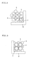
cell blocks 3 are formed at right angle at thecorner portions 7 as shown in Fig. 2, flow of kneaded clay is deteriorated. Accordingly, concavo-convex portions may be formed on an extruded face of a resultant extruded body (honeycomb segment), and fine splits 40 may be generated on an outer wall as shown in Fig. 7(b). - The present invention is made in view of the above described problems heretofore, and aims to provide an extrusion die for a honeycomb body, which is possible to reduce strain generated on an extruded face of an extruded body after extrusion, possible to maintain a stable frictional force of extrusion, excellent in extrudability, and excellent in wear resistance.
- According to the present invention, there is provided a die for forming a honeycomb body, the die comprising a structure provided with: groovy slits formed on a front face thereof, the slits being formed by cell blocks; and provided with back holes on a back face thereof, each hole being communicatively connected with the slit, characterized in that the number of the cell blocks per one side of the die is even number.
- At the time, it is preferable in the present invention that curved portions be formed at four corners on an peripheral portion of the die and that a radius of curvature of the curved portions be 0.5 to 1.5 mm.
- Further, in the present invention, it is preferable that a die be made of cemented carbide having high wear resistance and that the cemented carbide be formed by compacting, followed by sintering at high temperature, metal carbide powder of transition metal element series with an iron group metal binder having toughness.
- At the time, it is preferable that the back holes are disposed at every one positions of the cell blocks and that a thickness of the die is 15 to 30 mm.
-
- Fig. 1 is a front perspective view showing an example of a corner portion of an extruded face formed by a die and a holding plate of the present invention and shows an example of a layout of cell blocks and back holes.
- Fig. 2 is a front perspective view showing an example of a layout of cell blocks and back holes at a corner portion of an extruded face formed by a conventional die and a conventional holding plate.
- Fig. 3 is a front perspective view showing another example of the layout of the cell blocks and the back holes at the corner portion of the extruded face formed by the conventional die and the conventional holding plate.
- Fig. 4 is a schematic sectional view showing an example of a die for forming a honeycomb body.
- Fig. 5 is an explanatory view showing a relation between cell blocks and back holes.
- Fig. 6 is a configurational view showing an example of a die jig for forming a honeycomb body.
- Figs. 7(a) and 7(b) show a shape of an extruded honeycomb structure, in which Fig. 7(a) shows a case in which the die of Fig. 1 is used, and Fig. 7(b) shows a case in which the die of Fig. 2 is used.
-
- Detailed description will be made below on embodiments of the present invention on the basis of the drawings.
- Fig. 1 is a front perspective view showing an example of a corner portion of an extruded face formed by a die and a holding plate of the present invention and shows an example of a layout of cell blocks and back holes.
- At the time, a main feature of the die of the present invention (which is designed to provide one
back hole 4 every four cell blocks) resides in that the number N of cell blocks per one side of the die is set to even number ( refer to Fig. 4). - With the above arrangement, when a honeycomb cegment is executed using a die having a square honeycomb structure (in particular, when a honeycomb segment whose outer wall thickness is not large is extruded), the
cell blocks 3 and theback holes 4 at thecorner portions 7 can be uniformly designed at four upper, lower, right, and left corners as shown in Fig. 1. Accordingly, an extruding speed of kneaded clay in slits 9 formed by aholding plate 12 and thecorner portions 7 and an extruding speed thereof inslits 2 formed in the die can be made uniform, which can prevent distortion generated on an extruded face (pattern) of an extruded body and bending of the formed body. - Further, as shown in Fig. 1, it is preferable that the die of the present invention have curved
portions 8 at four corners of a peripheral portion of the die and that thecurved portions 8 have a radius of curvature r of 0.5 to 1.5 mm. - With the above arrangement, when the honeycomb segment is executed using the die having the square honeycomb structure (in particular, when the honeycomb segment whose outer wall thickness is not large is extruded), a formed body having an excellent extruded face and an excellently attached outer wall can be obtained as shown in Fig. 7(a) without uneven portions on the extruded face and without generation of fine splits 40 on the outer wall (refer to Fig. 7(b)).
- Further, the die of the present invention is preferably made of cemented carbide having high wear resistance.
- With the above arrangement, even if a raw material containing a material having very high hardness such as SiC and the like is extruded, the wear resistance (life) of the the die can be enhanced as well as a defect in shape of the die due to wear thereof can be overcome.
- Although there is not particular restriction as to the cemented carbide, it is preferably formed by compacting, followed by sintering at high temperature, metal carbide powder of transition metal element series, for example, WC, TiC, TaC, etc. with an iron group metal binder having high toughness such as Co, Ni, etc.
- Further, the die of the present invention preferably has a thickness (t) of 15 to 30 mm (more preferably 15 to 24 mm) (refer to Fig. 4).
- The thickness of the die is determined in consideration of strength of the die and flow of kneaded clay when a honeycomb body is extruded.
- At the time, when the die is excessively thick, it is improper because not only accuracy of the back holes machined by a drill and the like is deteriorated but also strain due to contraction in final sintering is increased. In contrast, when the is excessively thin, it is broken when a honeycomb structure is extruded by the die due to its insufficient strength.
- Note that when the honeycomb structure is formed, kneaded clay can stably flow in the die by making a back hole portion as short as possible because a flow resistance in length is reduced thereby.
- Further, in the present invention, when cemented carbide is used as a material of the die, it is preferable to dispose a back hole at every other positions of the cell blocks because the cell blocks are liable to be broken when a connecting area of the back holes and the cell blocks is excessively small.
- The present invention will further be described hereinafter in detail based on examples, but the present invention is not limited to these examples.
- After WC-Co (composite body of tungsten carbide and cobalt) powder as cemented carbide was formed into a square plate of 100 mm on a side and 40 mm in thickness (100 × 100 × 40 t) by press work and the like, it was calcined at 500 to 700°C. Thereafter, back holes having a predetermined diameter and a predetermined depth were drilled with a predetermined pitch from one end face of the square plate, and then the square plate was subjected to final sintering at 1000 to 1300°C, thereby it was contracted up to a square plate of 24 mm in thickness and 70 mm on a side (70 × 70 × 24 t). Thereafter, a predetermined dimension of the square plate was accurately obtained by polishing the entire surface thereof.
- Next, a cemented carbide die whose slit width and die shape were formed square was obtained by forming slits on the other face of the thus obtained square plate in a grid pattern at every other positions of the back holes, which were previously formed on one face of the square plate, by wire cut electric-discharge machining, or creep feed grinding or plunge cut grinding with diamond abrasive grain.
- The die for forming a honeycomb body was set to a die jig shown in Fig. 6, and a honeycomb structure was extruded using kneaded clay composed of raw material of argillaceous Si-SiC.
- Note that the kneaded clay was obtained by kneading a raw material made of metal silicon (Me-Si) and SiC which were prepared at a ratio of 25:75 and to which water, an organic binder, and a hole forming material were added.
- Honeycomb structures were extruded, respectively using cemented carbide dies shown in Table 1 (example 1, comparative examples 1 to 2). The results are shown in Table 1.

- From the results of Table 1, when the number of the cell blocks per one side of the die was even number and the back holes were disposed at every one positions of the cell blocks in the back hole structure of the die as shown in Fig. 1 (example 1), back hole area ratios could be set to the same ratio in respective corner portions. Accordingly, strain, which was generated on an extruded face (pattern) of a honeycomb structure after extrusion, and bending of an extruded body could be prevented.
- In contrast, when the number of the cell blocks per one side of the die was odd number and the back holes were disposed at every one positions of the cell blocks in the back hole structure of the die as shown in Fig. 2 (comparative example 1), back hole area ratios had an area difference of about 15% in a diagonal line direction at respective corner portions. Accordingly, strain, which was generated on an extruded face (pattern) of a honeycomb structure after extrusion, and bending of an extruded body were generated.
- Further, when the number of the cell blocks per one side of the die was even number and all the holes were made to back holes with respect to the cell blocks in the back hole structure of the die as shown in Fig. 3 (comparative example 2), back hole area ratios could be set to the same ratio at respective corner portions. Accordingly, strain, which was generated on an extruded face (pattern) of a honeycomb structure after extrusion, and bending of a formed body could be prevented. However, the die was broken because its strength was insufficient.
- Honeycomb structures were extruded, respectively using cemented carbide dies shown in Fig.1 having
curved portions 8 shown in Table 2, thecurved portions 8 being formed tocorner portions 7 ofcell blocks 3 on an outermost peripheral portion of the die. The results are shown in Table 2.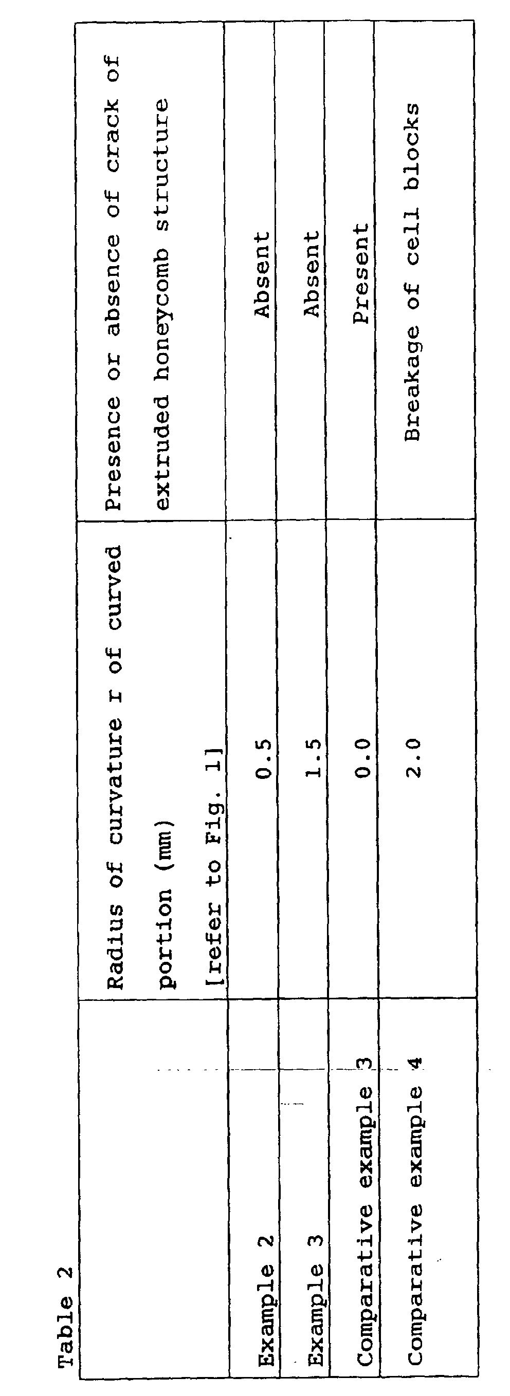
- From the results of Table 2, the present invention could prevent occurrence of cracks at the
corner portions 7 of a honeycomb structure after extrusion by setting a radius of curvature r of acurved portion 8 to 0.5 to 1.5 mm with respect to a length of a side of a cell block (examples 2 to 3). - In contrast, in a comparative example 3, cracks were generated at
corner portions 7 of a honeycomb structure after extrusion. This is because that the comparative example 3 had nocurved portions 8, and thus a small amount of kneaded clay flew from back holes of thecorner portions 7. - Further, in a comparative example 4, when a honeycomb structure was extruded, cell blocks were broken. This is because that a radius of curvature r of
curved portions 8 exceeded 1.5 mm, and thus a die had an insufficient strength. - After WC-Co (composite body of tungsten carbide and cobalt) powder as cemented carbide was formed into a square plate of 100 mm on a side and 40 mm in thickness (100 × 100 × 40 t), it was tentatively sintered at 500 to 700°C. Thereafter, back holes having a predetermined diameter and a predetermined depth were drilled with a predetermined pitch from one end face of the square plate, and then the square plate was subjected to final sintering at 1000 to 1300°C, thereby it was contracted up to a square plate of 24 mm in thichness and 70 mm on a side (70 × 70 × 24 t). Thereafter, a predetermined dimension of the square plate was accurately obtained by polishing the entire surface thereof.
- Next, a cemented carbide die whose slit width and die shape were formed in a square shape was obtained by forming slits on the other end surface of the thus obtained square plate in a grid pattern at every other positions of the back holes, which were previously formed on one face of the square plate, by wire cut electric discharge machining, or creep feed grinding or plunge cut grinding with diamond abrasive grain.
- Next, honeycomb structures were extruded, respectively using the thus obtained dies. The results are shown in Table 3.

- From the results of Table 3, it was confirmed that a thickness (t) of the die (refer to Fig. 4) was preferably set to 15 to 30 mm as a result that strength of the die, and a flow rate of kneaded clay in extrusion of an extruded body were optimized. (Comparative example 4 to 5)
- At the time, a die whose thickness was excessively large as in the comparative example 6 was improper because not only an accuracy of the back holes machined by a drill and the like was deteriorated but also strain due to contraction in final sintering was increased.
- In contrast, when a thickness of the die was excessively small as in the comparative example 5, the die was broken due to insufficient strength of the die when a honeycomb structure was extruded.
- The die for forming a honeycomb body of the present invention is possible to reduce strain generated on an extruded face of the honeycomb body after extrusion, possible to maintain a stable frictional force of extrusion, excellent in extrudability, and excellent in wear resistance.
Claims (6)
- A die for forming a honeycomb body, the die comprising a structure provided with:characterized in that the number of the cell blocks per one side of the die is even number.groovy slits formed on a front face thereof, the slits being formed by cell blocks; andback holes on a back face thereof, each hole being communicatively connected with the slit,
- A die for forming a honeycomb body according to claim 1, wherein curved portions are formed at four corners on an peripheral portion of the die, and a radius of curvature of the curved portions is 0.5 to 1.5 mm.
- A die for forming a honeycomb body according to claim 1 or 2, wherein the die is made of cemented carbide having high wear resistance.
- A die for forming a honeycomb body according to claim 3, wherein the cemented carbide is formed by compacting, followed by sintering at high temperature, metal carbide powder of transition metal element series with an iron group metal binder having toughness.
- A die for forming a honeycomb body according to any of claims 1 to 4, wherein the back holes are disposed at every one positions of the cell blocks.
- A die for forming a honeycomb body according to any of claims 1 to 5, wherein a thickness of the die is 5 to 30 µm.
Applications Claiming Priority (3)
| Application Number | Priority Date | Filing Date | Title |
|---|---|---|---|
| JP2002091034A JP2003285309A (en) | 2002-03-28 | 2002-03-28 | Honeycomb molding die |
| JP2002091034 | 2002-03-28 | ||
| PCT/JP2003/001031 WO2003082539A1 (en) | 2002-03-28 | 2003-01-31 | Honeycomb forming ferrule |
Publications (3)
| Publication Number | Publication Date |
|---|---|
| EP1502720A1 true EP1502720A1 (en) | 2005-02-02 |
| EP1502720A4 EP1502720A4 (en) | 2005-11-23 |
| EP1502720B1 EP1502720B1 (en) | 2009-08-19 |
Family
ID=28671673
Family Applications (1)
| Application Number | Title | Priority Date | Filing Date |
|---|---|---|---|
| EP03745398A Expired - Lifetime EP1502720B1 (en) | 2002-03-28 | 2003-01-31 | Honeycomb forming die |
Country Status (8)
| Country | Link |
|---|---|
| US (1) | US7311510B2 (en) |
| EP (1) | EP1502720B1 (en) |
| JP (1) | JP2003285309A (en) |
| KR (1) | KR100602471B1 (en) |
| AU (1) | AU2003258803A1 (en) |
| DE (1) | DE60328884D1 (en) |
| PL (1) | PL202011B1 (en) |
| WO (1) | WO2003082539A1 (en) |
Families Citing this family (10)
| Publication number | Priority date | Publication date | Assignee | Title |
|---|---|---|---|---|
| JP5134364B2 (en) | 2005-03-17 | 2013-01-30 | 日本碍子株式会社 | Method for manufacturing die for forming honeycomb structure and die for forming honeycomb structure |
| CN101242937B (en) * | 2005-10-05 | 2011-05-18 | 揖斐电株式会社 | Die for extrusion molding and process for producing porous ceramic member |
| JP2007302542A (en) * | 2006-05-15 | 2007-11-22 | Denso Corp | Jig for firing ceramic honeycomb molded body |
| WO2008143028A1 (en) * | 2007-05-18 | 2008-11-27 | Ngk Insulators, Ltd. | Die for molding honeycomb segment and method of producing honeycomb structure |
| JP5361224B2 (en) * | 2008-03-17 | 2013-12-04 | 日本碍子株式会社 | Die for forming honeycomb structure and method for manufacturing the same |
| JP5255940B2 (en) * | 2008-07-23 | 2013-08-07 | イビデンエンジニアリング株式会社 | Mold manufacturing method and mold |
| JP5379460B2 (en) * | 2008-12-05 | 2013-12-25 | 日本碍子株式会社 | Die for forming honeycomb structure and method for manufacturing the die for forming honeycomb structure |
| JP2016175789A (en) * | 2015-03-19 | 2016-10-06 | 日本碍子株式会社 | Honeycomb structure |
| EP3414067B1 (en) * | 2016-02-11 | 2022-06-15 | Corning Incorporated | Extrusion components for honeycomb bodies |
| JP6810083B2 (en) * | 2018-03-27 | 2021-01-06 | 日本碍子株式会社 | A method for manufacturing a base for forming a honeycomb structure and a method for manufacturing a honeycomb structure. |
Family Cites Families (15)
| Publication number | Priority date | Publication date | Assignee | Title |
|---|---|---|---|---|
| JPS583802B2 (en) * | 1979-09-12 | 1983-01-22 | 株式会社日本自動車部品総合研究所 | Manufacturing method for honeycomb molding dies |
| JPS5672905A (en) * | 1979-11-20 | 1981-06-17 | Ngk Insulators Ltd | Honeycomb structure extruding die and its manufacture |
| US4557773A (en) * | 1981-07-15 | 1985-12-10 | Corning Glass Works | Method for selectively manifolding honeycomb structures |
| US4486934A (en) * | 1982-01-11 | 1984-12-11 | General Motors Corporation | Monolith extrusion die construction method |
| JPH084749B2 (en) * | 1985-01-21 | 1996-01-24 | 日本碍子株式会社 | Ceramic honeycomb structure |
| WO1987005855A1 (en) * | 1986-03-26 | 1987-10-08 | Catalysts & Chemicals Industries Co., Ltd. | Die for molding honeycomb structures |
| JPH0356354Y2 (en) * | 1986-04-08 | 1991-12-18 | ||
| DE4402281A1 (en) * | 1994-01-27 | 1995-08-10 | Sf Koop Gmbh Beton Konzepte | Method of manufacturing Concrete paving blocks |
| JPH0890534A (en) * | 1994-09-29 | 1996-04-09 | Babcock Hitachi Kk | Honeycomb molding die |
| US6193497B1 (en) * | 1997-03-10 | 2001-02-27 | Ngk Insulators, Ltd. | Honeycomb extrusion die |
| JPH10264125A (en) * | 1997-03-28 | 1998-10-06 | Ngk Insulators Ltd | Ceramic honeycomb structure |
| JP2000071225A (en) * | 1998-09-01 | 2000-03-07 | Hoden Seimitsu Kako Kenkyusho Ltd | Honeycomb structure extrusion mold |
| JP4332980B2 (en) | 1999-03-18 | 2009-09-16 | 株式会社デンソー | Manufacturing method of mold for forming honeycomb structure |
| ES2341274T3 (en) * | 1999-09-29 | 2010-06-17 | Ibiden Co., Ltd. | PANAL FILTER AND CERAMIC FILTER ASSEMBLY. |
| JP3715174B2 (en) * | 2000-04-18 | 2005-11-09 | 日本碍子株式会社 | Manufacturing method of ceramic body |
-
2002
- 2002-03-28 JP JP2002091034A patent/JP2003285309A/en active Pending
-
2003
- 2003-01-31 US US10/507,413 patent/US7311510B2/en not_active Expired - Lifetime
- 2003-01-31 AU AU2003258803A patent/AU2003258803A1/en not_active Abandoned
- 2003-01-31 DE DE60328884T patent/DE60328884D1/en not_active Expired - Lifetime
- 2003-01-31 WO PCT/JP2003/001031 patent/WO2003082539A1/en not_active Ceased
- 2003-01-31 PL PL373707A patent/PL202011B1/en unknown
- 2003-01-31 EP EP03745398A patent/EP1502720B1/en not_active Expired - Lifetime
- 2003-01-31 KR KR1020047015116A patent/KR100602471B1/en not_active Expired - Lifetime
Non-Patent Citations (2)
| Title |
|---|
| No further relevant documents disclosed * |
| See also references of WO03082539A1 * |
Also Published As
| Publication number | Publication date |
|---|---|
| US7311510B2 (en) | 2007-12-25 |
| PL373707A1 (en) | 2005-09-05 |
| EP1502720B1 (en) | 2009-08-19 |
| JP2003285309A (en) | 2003-10-07 |
| DE60328884D1 (en) | 2009-10-01 |
| KR100602471B1 (en) | 2006-07-19 |
| EP1502720A4 (en) | 2005-11-23 |
| US20050147707A1 (en) | 2005-07-07 |
| WO2003082539A1 (en) | 2003-10-09 |
| PL202011B1 (en) | 2009-05-29 |
| AU2003258803A1 (en) | 2003-10-13 |
| KR20040104547A (en) | 2004-12-10 |
Similar Documents
| Publication | Publication Date | Title |
|---|---|---|
| US7858007B2 (en) | Honeycomb forming die and jig for honeycomb forming die using the same | |
| US8556615B2 (en) | Die for forming honeycomb structure and manufacturing method of the same | |
| US5070588A (en) | Process for producing ceramic honeycomb structure extrusion dies | |
| JP6046712B2 (en) | Die for forming honeycomb structure and method for manufacturing the same | |
| US7311510B2 (en) | Honeycomb forming die | |
| EP2221156A2 (en) | Die for forming honeycomb structure | |
| JP5134364B2 (en) | Method for manufacturing die for forming honeycomb structure and die for forming honeycomb structure | |
| EP2857163A1 (en) | Spinneret for molding honeycomb structure and manufacturing method therefor | |
| WO2003039826A1 (en) | Honeycomb extrusion molding mouth ring | |
| US8779332B2 (en) | Method for manufacturing honeycomb structure forming die | |
| EP1658945B1 (en) | Die for forming honeycomb structure and method of manufacturing honeycomb structure | |
| JP4220814B2 (en) | Cutting tool and manufacturing method thereof | |
| JPH05131426A (en) | Extrusion molding die for honeycomb structure and production thereof | |
| JP3954896B2 (en) | Cutting tool with breaker | |
| JP2006088556A (en) | Mold for molding ceramic honeycomb structure | |
| JP2004249404A (en) | Cutting tools | |
| JP2004202597A (en) | Cutting tools | |
| JP2005081609A (en) | Die for forming ceramic honeycomb structure and its manufacturing method |
Legal Events
| Date | Code | Title | Description |
|---|---|---|---|
| PUAI | Public reference made under article 153(3) epc to a published international application that has entered the european phase |
Free format text: ORIGINAL CODE: 0009012 |
|
| 17P | Request for examination filed |
Effective date: 20041018 |
|
| AK | Designated contracting states |
Kind code of ref document: A1 Designated state(s): AT BE BG CH CY CZ DE DK EE ES FI FR GB GR HU IE IT LI LU MC NL PT SE SI SK TR |
|
| AX | Request for extension of the european patent |
Extension state: AL LT LV MK RO |
|
| A4 | Supplementary search report drawn up and despatched |
Effective date: 20051007 |
|
| 17Q | First examination report despatched |
Effective date: 20080214 |
|
| GRAP | Despatch of communication of intention to grant a patent |
Free format text: ORIGINAL CODE: EPIDOSNIGR1 |
|
| GRAS | Grant fee paid |
Free format text: ORIGINAL CODE: EPIDOSNIGR3 |
|
| GRAA | (expected) grant |
Free format text: ORIGINAL CODE: 0009210 |
|
| AK | Designated contracting states |
Kind code of ref document: B1 Designated state(s): DE FR |
|
| REF | Corresponds to: |
Ref document number: 60328884 Country of ref document: DE Date of ref document: 20091001 Kind code of ref document: P |
|
| PLBE | No opposition filed within time limit |
Free format text: ORIGINAL CODE: 0009261 |
|
| STAA | Information on the status of an ep patent application or granted ep patent |
Free format text: STATUS: NO OPPOSITION FILED WITHIN TIME LIMIT |
|
| 26N | No opposition filed |
Effective date: 20100520 |
|
| REG | Reference to a national code |
Ref country code: FR Ref legal event code: PLFP Year of fee payment: 14 |
|
| REG | Reference to a national code |
Ref country code: FR Ref legal event code: PLFP Year of fee payment: 15 |
|
| REG | Reference to a national code |
Ref country code: FR Ref legal event code: PLFP Year of fee payment: 16 |
|
| PGFP | Annual fee paid to national office [announced via postgrant information from national office to epo] |
Ref country code: FR Payment date: 20211217 Year of fee payment: 20 |
|
| PGFP | Annual fee paid to national office [announced via postgrant information from national office to epo] |
Ref country code: DE Payment date: 20211207 Year of fee payment: 20 |
|
| REG | Reference to a national code |
Ref country code: DE Ref legal event code: R071 Ref document number: 60328884 Country of ref document: DE |