EP1502494A1 - Device for wrapping or packing in particular bales of harvested material - Google Patents
Device for wrapping or packing in particular bales of harvested material Download PDFInfo
- Publication number
- EP1502494A1 EP1502494A1 EP04017615A EP04017615A EP1502494A1 EP 1502494 A1 EP1502494 A1 EP 1502494A1 EP 04017615 A EP04017615 A EP 04017615A EP 04017615 A EP04017615 A EP 04017615A EP 1502494 A1 EP1502494 A1 EP 1502494A1
- Authority
- EP
- European Patent Office
- Prior art keywords
- clamping
- clamping element
- wrapping
- movable
- packaging material
- Prior art date
- Legal status (The legal status is an assumption and is not a legal conclusion. Google has not performed a legal analysis and makes no representation as to the accuracy of the status listed.)
- Granted
Links
- 239000000463 material Substances 0.000 title description 9
- 238000012856 packing Methods 0.000 title 1
- 238000004804 winding Methods 0.000 claims abstract description 11
- 230000006835 compression Effects 0.000 claims abstract description 5
- 238000007906 compression Methods 0.000 claims abstract description 5
- 239000005022 packaging material Substances 0.000 claims description 22
- 238000005520 cutting process Methods 0.000 claims description 11
- 238000004806 packaging method and process Methods 0.000 claims description 8
- 238000003825 pressing Methods 0.000 abstract description 3
- 238000004146 energy storage Methods 0.000 description 12
- 238000000034 method Methods 0.000 description 5
- 238000000926 separation method Methods 0.000 description 4
- 238000005516 engineering process Methods 0.000 description 3
- 238000003860 storage Methods 0.000 description 2
- 241000125258 Scandix pecten-veneris Species 0.000 description 1
- 230000009286 beneficial effect Effects 0.000 description 1
- 230000001419 dependent effect Effects 0.000 description 1
- 230000003292 diminished effect Effects 0.000 description 1
- 238000004519 manufacturing process Methods 0.000 description 1
- 229920006280 packaging film Polymers 0.000 description 1
- 239000012785 packaging film Substances 0.000 description 1
- 238000004886 process control Methods 0.000 description 1
- 239000010902 straw Substances 0.000 description 1
- 239000002699 waste material Substances 0.000 description 1
Images


Classifications
-
- A—HUMAN NECESSITIES
- A01—AGRICULTURE; FORESTRY; ANIMAL HUSBANDRY; HUNTING; TRAPPING; FISHING
- A01F—PROCESSING OF HARVESTED PRODUCE; HAY OR STRAW PRESSES; DEVICES FOR STORING AGRICULTURAL OR HORTICULTURAL PRODUCE
- A01F15/00—Baling presses for straw, hay or the like
- A01F15/07—Rotobalers, i.e. machines for forming cylindrical bales by winding and pressing
- A01F15/071—Wrapping devices
Definitions
- the invention relates to a device for wrapping or packaging of in particular agricultural crop bales of hay, straw or wilted Green waste.
- the invention relates to a, comprising a pressing chamber agricultural picking press for the production of harvested bales, with a wrapping or packaging material receiving winding unit, the one a movable actuating means having clamping device for fixing a Associated with packaging or wrapping material web, which is one of the movable Having actuating means in a clamping position convertible clamping element.
- a device of the type mentioned in the form of an agricultural Round baler in which the pressing chamber a winding unit with a Changing table and rotatably displaceable, carrying a winding roll Winding bodies are arranged downstream, wherein a Erntegutballen with the wrapping material is wrapped by the winding body until it is completely wrapped.
- a clamping element provided by a lifting cylinder moved into its clamping position and is moved out of this again.
- the respective lifting cylinder is to be controlled separately, both for Exercise the corresponding stroke movement until the clamping position is taken, but also by acting on the opposing piston surface in a lifting movement back to release the web.
- This is also in terms of time Adjusting winding process control technology, which in practice coordination expenses caused.
- the device of the type mentioned is characterized characterized in that the clamping element of the adjusting means against the force of a Force accumulator in its clamping position and transferred from the energy storage in a located outside of the clamping position and predetermined by the energy storage Operating position is movable.
- a device in which the clamping element is not by a controlled lifting movement of the actuating means in a Hüllstoff- or packaging material web releasing operating position is to be transferred, as this movement through the Power storage itself can be exercised. It is easier in control technology It is therefore possible, after a certain time interval after the start of a wrapping process to put the actuating means in a state that it is the clamping element no longer holds in its clamping position. For example, an as Hydraulic cylinder trained actuating means simply depressurized, so that in the Depressurize this actuator the energy storage reset the clamping element can not in an operating position in the Hüllstoff- or packaging material web is more clamped.
- the power storage not only has the task that Clamping element in this, no clamping force more exerting operating position convict, but also the position of the clamping element after the return movement to determine from the clamping position.
- This is in a structurally simple way by to perform a compression spring, so that this predetermined by the energy storage Operating position by the degree of deflection of this pressure spring can be predetermined.
- the energy storage device can during the transfer of the clamping element in the clamping position store the corresponding force, e.g. a compression spring compressed becomes. With this stored force, the clamping element is then in the predetermined operating position transferred, after which the wrapping or packaging material web can rest relatively loosely on the clamping element and pull out as needed is.
- the coordination of control tasks during the Envelopment process is thus considerably simplified, since only after a relative short time interval after the beginning of the winding process, in which the wrapping or Packaging material or its corresponding webs securely on the to be wrapped or to be packaged crop, the adjusting means e.g. simply depressurized is to make. The resulting movement is automatically from the energy storage initiated, without further control tasks are to be done.
- a device for wrapping or packaging of particular agricultural crop bales provided with a diminished Tax expense and manage a wrapping or packaging material web in the Clamping reliably holds, but even if the e.g. as a hydraulic cylinder trained adjusting means is depressurized, in a simple way, a repeal the clamping action and thus a removal of the film web from the device allows. Threading a material sheet, e.g. after replacing one Film roll material is also much easier in the device according to the invention to accomplish than in the prior art.
- the clamping element is designed as a clamping pliers that with a Clamping bar cooperates.
- This clamping bar can have a spring on this have supported clamping rail.
- On the clamping bar is beyond the Force memory interchangeable set.
- the clamping element and in the rest of the clamping bar as a whole so designed that they like a Schnabels are open, with the clamping element of the clamping bar high can be pivoted into an operating position in which a maximum opening angle exists between clamping element and clamping bar.
- the clamping element facing away from the wrapping or packaging material web End guided translationally movable in a slot-shaped longitudinal guide, so that it in a pivoting movement of the clamping element from an open position in its clamping position can be moved translationally away to close the pliers.
- Such closing is especially necessary when a Hüllstoff- or Packaging material web to be folded on each other, wherein the folded Track sections by the pivotal movement of the clamping element and the associated Clamping bar should lie on each other. This is also beneficial for one subsequent separation or cutting process, since no longer the entire Hüllstoffbahnbreite a cutting tool or separating element is to be supplied.
- a cutting or Separating element provided for the Hüllstoff- or packaging material, namely such, for the intended separation or cutting process in the web the Hüllstoff- or packaging material can be pivoted.
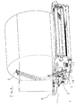
- the clamping device 1 has in the illustrated embodiment a movable actuating means 2 in the form of a lifting cylinder.
- she comprises a clamping element 3, which at its rear end 4 a Bolzenschraubtagen 5, which is guided in a slot-like longitudinal guide 6 in a housing is, on which also designed as a hydraulic cylinder actuating means 2 is supported.
- the clamping device 1 has next to the clamping element 3 nor a clamping bar 7, on which via a driver 8 acts as the lifting cylinder designed actuating means 2, wherein the clamping element 3 and the clamping bar 7 form a clamping pliers.
- the Clamping element 3 is in turn fork-shaped and acts with the clamping bar 7 together, which in turn has a clamping rail 12, the interposition supported by spring elements 13 and 14 on the clamping bar interchangeable is.
- the fork-shaped clamping element 3 can therefore the clamping rail 12 and partially overlap the clamping bar 7 and in between a piece of track Wrap wrapping or packaging material on the clamping rail 12, when the trained as a lifting cylinder actuating means 2 brought into its extended position is, as shown in FIG. 1. In this position, the rear end 4 and the bolt is the fifth of the clamping element within the longitudinal guide 6 completely moved backwards, so that the clamping element together with the clamping bar 7 is an approximately horizontal position occupies.
- an energy storage 15 in the form of a Compression spring provided on the clamping bar 7 .
- the clamping element 3 After the transfer of the clamping element 3 in the in Fig.1 shown clamping position presses the clamping element 3 on the energy storage 15 us spurs this forward. If the actuating means 2 is depressurized, can under the action of the energy accumulator 15, the clamping element 3 in such an operating position raise or slightly swivel that the clamping of the wrapping or packaging material no longer persists. However, the clamping element will also be only to raise such an area as the deflection of the energy storage 15th allows. Thereafter, the wrapping or packaging material is still running, however not clamped by the clamping element 3.
- Fig. 2 designed as a hydraulic cylinder actuating means 2 is shown retracted and has thus moved the driver 8 in the direction of the actuating means 2, so that due the pivotal support by the bolt 19 within the housing 11th the clamping bar 7 together with the clamping rail 12, the spring elements 13 and 14th and the energy storage 15 in the swung up, illustrated open position is pivoted. Due to its articulated connection at 16, the clamping element 3 pivoted in the pivoted-open position, and under appeal of the end 4 and the pin 5 in the slot guide 6.
Landscapes
- Life Sciences & Earth Sciences (AREA)
- Environmental Sciences (AREA)
- Basic Packing Technique (AREA)
- Storage Of Harvested Produce (AREA)
- Packaging Of Special Articles (AREA)
Abstract
Description
Die Erfindung bezieht sich auf eine Vorrichtung zum Umhüllen oder Verpacken von insbesondere landwirtschaftlichem Erntegutballen aus Heu, Stroh oder angewelktem Grüngut. Vorzugsweise bezieht sich die Erfindung auf eine, eine Presskammer umfassende landwirtschaftliche Aufsammelpresse zur Herstellung von Erntegutballen, mit einer Umhüllungs- bzw. Verpackungsmaterial aufnehmenden Wickeleinheit, der eine ein bewegliches Stellmittel aufweisende Klemmvorrichtung zur Festlegung einer Verpackungs- bzw. Umhüllungsmaterialbahn zugeordnet ist, die ein von dem beweglichen Stellmittel in eine Klemmstellung überführbares Klemmelement aufweist.The invention relates to a device for wrapping or packaging of in particular agricultural crop bales of hay, straw or wilted Green waste. Preferably, the invention relates to a, comprising a pressing chamber agricultural picking press for the production of harvested bales, with a wrapping or packaging material receiving winding unit, the one a movable actuating means having clamping device for fixing a Associated with packaging or wrapping material web, which is one of the movable Having actuating means in a clamping position convertible clamping element.
Eine Vorrichtung der eingangs genannten Art in Gestalt einer landwirtschaftlichen Rundballenpresse ist bekannt, bei der der Presskammer eine Wickeleinheit mit einem Wickeltisch und in Rotationsbewegung versetzbaren, eine Wickelrolle tragenden Wickelkörpern nachgeordnet sind, wobei ein Erntegutballen mit dem Umhüllungsmaterial durch die Wickelkörper solange umwickelt wird, bis er vollständig eingehüllt ist. Zum Festlegen der Umhüllungsmaterialbahn, insbesondere zu Beginn eines Wickelvorganges aber auch zum Festlegen der Umhüllungsmaterialbahn während eines Trenn- bzw. Schneidvorganges ist hierbei ein Klemmelement vorgesehen, das von einem Hubzylinder in seine Klemmstellung bewegt und aus dieser auch wieder herausbewegt wird. Dazu ist der jeweilige Hubzylinder gesondert anzusteuern, und zwar sowohl zur Ausübung der entsprechenden Hubbewegung, bis die Klemmstellung eingenommen ist, aber auch durch Beaufschlagung der gegensinnigen Kolbenfläche in eine Hubbewegung zurück, um die Materialbahn freizugeben. Dies ist auch in zeitlicher Hinsicht dem Wickelvorgang steuerungstechnisch anzupassen, was in der Praxis Koordinationsaufwendungen verursacht.A device of the type mentioned in the form of an agricultural Round baler is known in which the pressing chamber a winding unit with a Changing table and rotatably displaceable, carrying a winding roll Winding bodies are arranged downstream, wherein a Erntegutballen with the wrapping material is wrapped by the winding body until it is completely wrapped. To the Determining the wrapping material web, in particular at the beginning of a winding process but also for fixing the wrapping material web during a separation or Cutting process here is a clamping element provided by a lifting cylinder moved into its clamping position and is moved out of this again. For this purpose, the respective lifting cylinder is to be controlled separately, both for Exercise the corresponding stroke movement until the clamping position is taken, but also by acting on the opposing piston surface in a lifting movement back to release the web. This is also in terms of time Adjusting winding process control technology, which in practice coordination expenses caused.
Es ist Aufgabe der vorliegenden Erfindung, eine Vorrichtung der eingangs genannten Art hinsichtlich des steuerungstechnischen Aufwandes für den Umhüllungsvorgang zu vereinfachen.It is an object of the present invention, a device of the aforementioned Type with regard to the control-technical effort for the wrapping process simplify.
Zur Lösung dieser Aufgabe zeichnet sich die Vorrichtung der eingangs genannten Art dadurch aus, dass das Klemmelement von dem Stellmittel gegen die Kraft eines Kraftspeichers in seine Klemmstellung überführbar und von dem Kraftspeicher in eine außerhalb der Klemmstellung gelegene sowie von dem Kraftspeicher vorgebbare Betriebsstellung bewegbar ist.To solve this problem, the device of the type mentioned is characterized characterized in that the clamping element of the adjusting means against the force of a Force accumulator in its clamping position and transferred from the energy storage in a located outside of the clamping position and predetermined by the energy storage Operating position is movable.
Dadurch ist eine Vorrichtung geschaffen, bei der das Klemmelement nicht durch eine gesteuerte Hubbewegung des Stellmittels in eine die Hüllstoff- bzw. Verpackungsmaterialbahn freigebende Betriebsstellung zu überführen ist, da diese Bewegung durch den Kraftspeicher selbst ausgeübt werden kann. Es ist in steuerungstechnisch einfacher Weise daher möglich, nach einem bestimmten Zeitintervall nach Beginn eines Umhüllungsvorganges das Stellmittel in einen Zustand zu versetzen, dass es das Klemmelement nicht mehr in seiner Klemmstellung hält. So ist beispielsweise ein als Hydraulikzylinder ausgebildetes Stellmittel einfach drucklos zu schalten, so dass in der Drucklosstellung dieses Stellmittels der Kraftspeicher das Klemmelement zurückstellen kann in eine Betriebsstellung, in der die Hüllstoff- bzw. Verpackungsmaterialbahn nicht mehr geklemmt ist. Der Kraftspeicher hat dabei allerdings nicht nur die Aufgabe, dass Klemmelement in diese, keine Klemmkraft mehr ausübende Betriebsstellung zu überführen, sondern auch die Position des Klemmelementes nach der Rückstellbewegung aus der Klemmstellung zu bestimmen. Dies ist in baulich einfacher Weise durch eine Druckfeder zu vollziehen, so dass diese durch den Kraftspeicher vorgegebene Betriebsstellung durch den Grad der Auslenkung dieser Druckfeder vorbestimmbar ist. As a result, a device is provided in which the clamping element is not by a controlled lifting movement of the actuating means in a Hüllstoff- or packaging material web releasing operating position is to be transferred, as this movement through the Power storage itself can be exercised. It is easier in control technology It is therefore possible, after a certain time interval after the start of a wrapping process to put the actuating means in a state that it is the clamping element no longer holds in its clamping position. For example, an as Hydraulic cylinder trained actuating means simply depressurized, so that in the Depressurize this actuator the energy storage reset the clamping element can not in an operating position in the Hüllstoff- or packaging material web is more clamped. However, the power storage not only has the task that Clamping element in this, no clamping force more exerting operating position convict, but also the position of the clamping element after the return movement to determine from the clamping position. This is in a structurally simple way by to perform a compression spring, so that this predetermined by the energy storage Operating position by the degree of deflection of this pressure spring can be predetermined.
Der Kraftspeicher kann während des Überführens des Klemmelementes in die Klemmstellung die entsprechende Kraft speichern, indem z.B. eine Druckfeder zusammengedrückt wird. Mit dieser gespeicherten Kraft wird das Klemmelement dann in die vorgebbare Betriebsstellung überführt, wonach die Umhüllung- bzw. Verpackungsmaterialbahn relativ locker an dem Klemmelement anliegen kann und bei Bedarf herauszuziehen ist. Die Koordination von Steuerungsaufgaben während des Umhüllungsprozesses ist damit wesentlich vereinfacht, da nur nach einem relativ kurzen Zeitintervall nach Beginn des Wickelvorganges, in dem das Umhüllungs- bzw. Verpackungsmaterial bzw. dessen entsprechende Bahnen sicher an dem zu umhüllenden bzw. zu verpackenden Erntegut festgelegt sind, das Stellmittel z.B. einfach drucklos zu stellen ist. Die sich danach ergebende Bewegung wird selbsttätig von dem Kraftspeicher eingeleitet, ohne dass weitere Steuerungsaufgaben zu erledigen sind.The energy storage device can during the transfer of the clamping element in the clamping position store the corresponding force, e.g. a compression spring compressed becomes. With this stored force, the clamping element is then in the predetermined operating position transferred, after which the wrapping or packaging material web can rest relatively loosely on the clamping element and pull out as needed is. The coordination of control tasks during the Envelopment process is thus considerably simplified, since only after a relative short time interval after the beginning of the winding process, in which the wrapping or Packaging material or its corresponding webs securely on the to be wrapped or to be packaged crop, the adjusting means e.g. simply depressurized is to make. The resulting movement is automatically from the energy storage initiated, without further control tasks are to be done.
Insgesamt ist mithin eine Vorrichtung zum Umhüllen bzw. Verpacken von insbesondere landwirtschaftlichem Erntegutballen zur Verfügung gestellt, die mit einem verminderten Steueraufwand auskommt und eine Umhüllungs- bzw. Verpackungsmaterialbahn in der Klemmstellung zuverlässig hält, aber auch dann wenn das z.B. als Hydraulikzylinder ausgebildete Stellmittel drucklos geschaltet wird, in einfacher Weise eine Aufhebung der Klemmwirkung und somit ein Entfernen der Folienbahn aus der Vorrichtung ermöglicht. Ein Einfädeln einer Material- bzw. Verpackungsmaterialfolie z.B. nach Ersatz einer Folienmaterialrolle ist bei der Vorrichtung nach der Erfindung auch wesentlich einfacher zu vollziehen als bei dem vorbekannten Stand der Technik.Overall, therefore, a device for wrapping or packaging of particular agricultural crop bales provided with a diminished Tax expense and manage a wrapping or packaging material web in the Clamping reliably holds, but even if the e.g. as a hydraulic cylinder trained adjusting means is depressurized, in a simple way, a repeal the clamping action and thus a removal of the film web from the device allows. Threading a material sheet, e.g. after replacing one Film roll material is also much easier in the device according to the invention to accomplish than in the prior art.
Bevorzugtermassen ist das Klemmelement als Klemmzange ausgebildet, das mit einem Klemmbalken zusammenwirkt. Dieser Klemmbalken kann eine über Federn an diesem abgestützte Klemmschiene haben. An dem Klemmbalken ist darüber hinaus der Kraftspeicher auswechselbar festzulegen. Vorzugsweise sind das Klemmelement und im übrigen auch der Klemmbalken insgesamt so ausgebildet, dass sie nach Art eines Schnabels zu öffnen sind, wobei das Klemmelement von dem Klemmbalken hoch verschwenkt werden kann in eine Betriebsstellung, in der ein maximaler Öffnungswinkel zwischen Klemmelement und Klemmbalken vorliegt. Vorteilhafterweise ist das Klemmelement an seinem der Umhüllungs- bzw. Verpackungsmaterialbahn abgewandten Ende in einer schlitzförmigen Längsführung translatorisch beweglich geführt, so dass es bei einer Verschwenkbewegung des Klemmelementes aus einer Öffnungsstellung in seine Klemmstellung translatorisch weg bewegt werden kann, um die Zange zu schlieen. Ein solches Schließen ist insbesondere dann geboten, wenn eine Hüllstoff- bzw. Verpackungsmaterialbahn aufeinander gefaltet werden soll, wobei die gefalteten Bahnabschnitte durch die Schwenkbewegung des Klemmelementes und des dazugehörigen Klemmbalkens aufeinander liegen sollen. Dieses ist auch vorteilhaft für einen nachfolgenden Trenn- bzw. Schneidvorgang, da nicht mehr die gesamte Hüllstoffbahnbreite einem Schneidwerkzeug bzw. Trennelement zuzuführen ist.Preferably, the clamping element is designed as a clamping pliers that with a Clamping bar cooperates. This clamping bar can have a spring on this have supported clamping rail. On the clamping bar is beyond the Force memory interchangeable set. Preferably, the clamping element and in the rest of the clamping bar as a whole so designed that they like a Schnabels are open, with the clamping element of the clamping bar high can be pivoted into an operating position in which a maximum opening angle exists between clamping element and clamping bar. Advantageously, the clamping element facing away from the wrapping or packaging material web End guided translationally movable in a slot-shaped longitudinal guide, so that it in a pivoting movement of the clamping element from an open position in its clamping position can be moved translationally away to close the pliers. Such closing is especially necessary when a Hüllstoff- or Packaging material web to be folded on each other, wherein the folded Track sections by the pivotal movement of the clamping element and the associated Clamping bar should lie on each other. This is also beneficial for one subsequent separation or cutting process, since no longer the entire Hüllstoffbahnbreite a cutting tool or separating element is to be supplied.
Bevorzugterweise ist auch in der Nachbarschaft des Klemmelementes ein Schneidoder Trennelement für das Hüllstoff- bzw. Verpackungsmaterial vorgesehen, und zwar ein solches, das sich für den beabsichtigten Trenn- bzw. Schneidvorgang in die Bahn des Hüllstoff- bzw. Verpackungsmaterials verschwenken lässt.Preferably, in the vicinity of the clamping element is a cutting or Separating element provided for the Hüllstoff- or packaging material, namely such, for the intended separation or cutting process in the web the Hüllstoff- or packaging material can be pivoted.
Weitere vorteilhafte Ausgestaltungen der Erfindung ergeben sich aus weiteren Unteransprüchen, der nachfolgenden Beschreibung und der Zeichnung. In der Zeichnung zeigen:
- Fig. 1
- ein Ausführungsbeispiel eines Klemmelementes mit zugehörigem Kraftspeicher in der Klemmstellung in einer perspektivischen Darstellung,
- Fig. 2
- eine zu Fig. 1 analoge Darstellung in geöffnetem hochverschwenktem Zustand des Klemmelementes, und
- Fig. 3
- eine Einzelteildarstellung der in den Fig. 1 und 2 veranschaulichten Teile der Vorrichtung in einer auseinander gezogenen Darstellung,
- Fig.4
- eine perspektivische Ansicht einer Vorrichtung zum Umhüllen und Verpacken in eine Phase vor dem Zusammenfalten und Abtrennen einer Verpackungsmaterialbahn.
- Fig. 1
- an embodiment of a clamping element with associated energy storage in the clamping position in a perspective view,
- Fig. 2
- an analogous to Fig. 1 representation in the open hochverschwenktem state of the clamping element, and
- Fig. 3
- an exploded view of the parts of the device illustrated in FIGS. 1 and 2, in an exploded view,
- Figure 4
- a perspective view of an apparatus for wrapping and packaging in a phase prior to folding and separating a packaging material web.
In der Zeichnung sind grundsätzlich gleichwirkende Teile mit übereinstimmenden Bezugsziffern versehen. In der Zeichnung ist die allgemeine Vorrichtung zum Umhüllen bzw. Verpacken von beispielsweise landwirtschaftlichem Erntegutballen aus Gründen der besseren Übersichtlichkeit nicht dargestellt. Die dargestellten Teile sind in vielfältiger Weise nutzbar, z.B. bei landwirtschaftlichen Maschinen wie etwa landwirtschaftlichen Ballenpressen aber auch an sonstigen Gerätschaften, mit der Gut durch Umhüllungs- oder Verpackungsmaterialbahnen zu umhüllen bzw. zu verpacken sind.In the drawing are basically the same parts with matching Reference numbers provided. In the drawing, the general device for wrapping or packaging, for example, agricultural crop bales for reasons the better clarity not shown. The parts shown are in more diverse Way usable, e.g. in agricultural machinery such as agricultural Balers but also on other equipment, with the good by Enveloping or packaging material webs to wrap or pack are.
Die in den Fig. 1 bis 3 dargestellte Klemmeinrichtung 1 ist beispielsweise an einer
landwirtschaftlichen Aufsammelpresse einer Presskammer nachgeordnet und an einem
Wickeltisch vorgesehen, und zwar im Wirkbereich von einem oder mehreren kreisenden
Wickelkörpern, so dass die Klemmeinrichtung eine Umhüllungs- oder Verpackungsmaterialbahn
ergreifen kann. Die Klemmeinrichtung 1 weist in dem dargestellten Ausführungsbeispiel
ein bewegliches Stellmittel 2 in Gestalt eines Hubzylinders auf. Sie
umfasst ein Klemmelement 3, das an seinem hinteren Ende 4 eine Bolzenschraubverbindung
5 hat, welches in einer schlitzartigen Längsführung 6 in einem Gehäuse geführt
ist, an dem auch das als Hydraulikzylinder ausgebildete Stellmittel 2 abgestützt ist.The
Die Klemmeinrichtung 1 hat neben dem Klemmelement 3 noch einen Klemmbalken 7,
an dem über einen Mitnehmer 8 das als Hubzylinder ausgeführte Stellmittel 2 angreift,
wobei das Klemmelement 3 und der Klemmbalken 7 eine Klemmzange ausbilden. Das
Klemmelement 3 ist seinerseits gabelförmig ausgebildet und wirkt mit dem Klemmbalken
7 zusammen, der seinerseits eine Klemmschiene 12 hat, die unter Zwischenschaltung
von Federelementen 13 und 14 auf dem Klemmbalken auswechselbar gehaltert
ist. Das gabelförmige Klemmelement 3 kann mithin die Klemmschiene 12 und bereichsweise
den Klemmbalken 7 übergreifen und dazwischen ein Bahnstück aus
Umhüllungs- oder Verpackungsmaterial an der Klemmschiene 12 festklemmen, wenn
das als Hubzylinder ausgebildete Stellmittel 2 in seine ausgefahrene Position gebracht
ist, wie dies Fig. 1 zeigt. In dieser Position ist das rückwärtige Ende 4 bzw. der Bolzen 5
des Klemmelementes innerhalb der Längsführung 6 vollständig nach hinten bewegt, so
dass das Klemmelement mitsamt dem Klemmbalken 7 eine in etwa waagerechte Lage
einnimmt.The
An dem Klemmbalken 7 ist darüber hinaus noch ein Kraftspeicher 15 in Gestalt einer
Druckfeder vorgesehen. Nach der Überführung des Klemmelementes 3 in die in Fig.1
dargestellte Klemmstellung drückt das Klemmelement 3 auf den Kraftspeicher 15 uns
spannt diesen vor. Wird das Stellmittel 2 drucklos gestellt, kann unter der Einwirkung
des Kraftspeichers 15 das Klemmelement 3 in eine solche Betriebsstellung anheben
bzw. leicht verschwenken, dass die Klemmung des Umhüllungs- bzw. Verpackungsmaterials
nicht mehr weiter fortbesteht. Dabei wird sich das Klemmelement allerdings auch
nur um einen solchen Bereich anheben, wie es die Auslenkung des Kraftspeichers 15
zulässt. Danach ist das Umhüllungs- oder Verpackungsmaterial noch geführt, jedoch
nicht von dem Klemmelement 3 festgeklemmt.On the
In Fig. 2 ist das als Hydraulikzylinder ausgeführte Stellmittel 2 eingefahren dargestellt
und hat mithin den Mitnehmer 8 in Richtung des Stellmittels 2 bewegt, so dass aufgrund
der schwenkbeweglichen Halterung durch den Bolzen 19 innerhalb des Gehäuses 11
der Klemmbalken 7 mitsamt der Klemmschiene 12, den Federelementen 13 und 14
sowie dem Kraftspeicher 15 in die hochgeschwenkt, dargestellte Öffnungsstellung
verschwenkt ist. Aufgrund seiner gelenkigen Verbindung bei 16 ist das Klemmelement 3
in die hochgeschwenkte Öffnungsstellung verschwenkt, und zwar unter Heranziehung
des Endes 4 bzw. des Bolzens 5 in der Schlitzführung 6. In dieser Position kann mittels
dieser geöffneten Zange, gebildet durch das Klemmelement 3, und den Klemmbalken 7,
ein Fangen des Umhüllungs- bzw. Verpackungsfolienmaterials erfolgen und gleichfalls
während des Hindurchführens umgelegt bzw. gefaltet werden, so dass eine Folienbahn
auf in etwa die Hälfte ihrer Breite oder weniger zusammengelegt ist und mithin mehrlagig
nach Betätigung des Stellmittels 2 durch das Klemmelement 3 festgeklemmt werden
kann. Für einen nachfolgenden Trennvorgang, teilweise wiedergegeben in Fig.4, mit
Hilfe des Trenn- und Schneidmessers 17, das sich in seiner Außerbetriebsstellung in
etwa parallel zum Klemmelement 3 erstreckt (sh. auch Fig. 1 und Fig. 3), wird mittels
eines Hebels 18 das Schneid- und Trennelement 17 in die Umlaufbahn des Umhüllungs-
bzw. Verpackungsmaterial geschwenkt, so dass das umgelegte oder gefaltete
Umhüllungs- bzw. Verpackungsbahnmaterial durchtrennt bzw. so perforiert wird, dass
es bei weiterer Zugbelastung reißt. Das Loslassen des Umhüllungs- und Verpackungsmaterials
ist bei der vorliegenden Vorrichtung in steuerungstechnisch einfacher Weise
allein dadurch zu vollziehen, dass das Stellmittel 2 drucklos geschaltet wird, wonach die
nachfolgende Freigabebewegung allein durch die Auslenkung des Kraftspeichers 15
vollzogen werden kann.In Fig. 2, designed as a hydraulic cylinder actuating means 2 is shown retracted
and has thus moved the
Claims (12)
Applications Claiming Priority (2)
| Application Number | Priority Date | Filing Date | Title |
|---|---|---|---|
| DE10334679 | 2003-07-30 | ||
| DE10334679A DE10334679B4 (en) | 2003-07-30 | 2003-07-30 | Apparatus for wrapping or packaging, in particular, agricultural crop bales |
Publications (2)
| Publication Number | Publication Date |
|---|---|
| EP1502494A1 true EP1502494A1 (en) | 2005-02-02 |
| EP1502494B1 EP1502494B1 (en) | 2007-09-26 |
Family
ID=33521472
Family Applications (1)
| Application Number | Title | Priority Date | Filing Date |
|---|---|---|---|
| EP04017615A Expired - Lifetime EP1502494B1 (en) | 2003-07-30 | 2004-07-26 | Device for wrapping or packing in particular bales of harvested material |
Country Status (3)
| Country | Link |
|---|---|
| EP (1) | EP1502494B1 (en) |
| AT (1) | ATE373949T1 (en) |
| DE (2) | DE10334679B4 (en) |
Cited By (1)
| Publication number | Priority date | Publication date | Assignee | Title |
|---|---|---|---|---|
| EP3138384A1 (en) * | 2015-09-07 | 2017-03-08 | Usines Claas France S.A.S | Winding device for a baler and method of operating the same |
Families Citing this family (2)
| Publication number | Priority date | Publication date | Assignee | Title |
|---|---|---|---|---|
| DE102009010547B3 (en) * | 2009-02-25 | 2010-06-24 | Siegfried Unseld | Cutting device for e.g. cutting foil web into wrap round balls, has shafts movable from working position for clamping process, and blade provided with drive, where working position resides at sides of material |
| DE202016004710U1 (en) | 2016-08-01 | 2017-11-03 | Pöttinger Landtechnik Gmbh | Bale Wrappers |
Citations (3)
| Publication number | Priority date | Publication date | Assignee | Title |
|---|---|---|---|---|
| EP0367529A1 (en) * | 1988-10-31 | 1990-05-09 | Kverneland Underhaug A/S | An automatic round bale wrapper |
| GB2249077A (en) * | 1990-09-19 | 1992-04-29 | Wellmount Ltd | Bale wrapping apparatus |
| FR2679105A1 (en) * | 1991-07-17 | 1993-01-22 | Doucet Freres | Machine for wrapping round bales of fodder |
Family Cites Families (2)
| Publication number | Priority date | Publication date | Assignee | Title |
|---|---|---|---|---|
| GB2242667B (en) * | 1990-04-03 | 1994-02-16 | Lawrence Edwards & Co | Improvements in or relating to wrapping apparatus |
| DE9414220U1 (en) * | 1994-09-02 | 1994-11-24 | Bräutigam, Klaus, Dipl.-Ing., 34281 Gudensberg | Device for wrapping silo bales |
-
2003
- 2003-07-30 DE DE10334679A patent/DE10334679B4/en not_active Expired - Fee Related
-
2004
- 2004-07-26 DE DE502004005065T patent/DE502004005065D1/en not_active Expired - Lifetime
- 2004-07-26 AT AT04017615T patent/ATE373949T1/en active
- 2004-07-26 EP EP04017615A patent/EP1502494B1/en not_active Expired - Lifetime
Patent Citations (3)
| Publication number | Priority date | Publication date | Assignee | Title |
|---|---|---|---|---|
| EP0367529A1 (en) * | 1988-10-31 | 1990-05-09 | Kverneland Underhaug A/S | An automatic round bale wrapper |
| GB2249077A (en) * | 1990-09-19 | 1992-04-29 | Wellmount Ltd | Bale wrapping apparatus |
| FR2679105A1 (en) * | 1991-07-17 | 1993-01-22 | Doucet Freres | Machine for wrapping round bales of fodder |
Cited By (1)
| Publication number | Priority date | Publication date | Assignee | Title |
|---|---|---|---|---|
| EP3138384A1 (en) * | 2015-09-07 | 2017-03-08 | Usines Claas France S.A.S | Winding device for a baler and method of operating the same |
Also Published As
| Publication number | Publication date |
|---|---|
| DE502004005065D1 (en) | 2007-11-08 |
| ATE373949T1 (en) | 2007-10-15 |
| DE10334679B4 (en) | 2005-10-20 |
| DE10334679A1 (en) | 2005-03-03 |
| EP1502494B1 (en) | 2007-09-26 |
Similar Documents
| Publication | Publication Date | Title |
|---|---|---|
| DE69709981T2 (en) | Round baler | |
| DE1782382C3 (en) | Loader wagon with a ball-forming loading device | |
| EP0157898B1 (en) | Wrapping mechanism for rotary balers | |
| EP0075252B1 (en) | Automatic twine device for a crop material roll forming machine | |
| DE3418681A1 (en) | Rolled-bale press for agricultural stalk crops, having a wrapping device | |
| DE102005055375B4 (en) | Round baler | |
| EP3391728B1 (en) | Baling press | |
| DE3436883A1 (en) | METHOD FOR PRODUCING RECTANGULAR LARGE BALES FROM CUTTED CROPS AND LARGE BALE PRESS | |
| EP0350514A1 (en) | Round-bale press | |
| DE68911838T2 (en) | Belt tensioning device for a round baler. | |
| DE3445060C2 (en) | ||
| DE2650615A1 (en) | DEVICE FOR COMPRESSING FARMED AGRICULTURAL WAX | |
| EP1401710B1 (en) | Knotter hook and cord knotter equipped with the same | |
| DE10153517B4 (en) | Binding device for a round baler | |
| EP1502494A1 (en) | Device for wrapping or packing in particular bales of harvested material | |
| EP1502495B1 (en) | Device for wrapping or packing in particular bales of harvested material | |
| EP1982576B1 (en) | Balling press with knotter | |
| EP3391729B1 (en) | Baling press | |
| EP3391734B1 (en) | Baling press | |
| EP0095681B1 (en) | Round baler | |
| EP1595439A2 (en) | Device for picking up and pressing of harvested agricultural crop | |
| EP4108069A1 (en) | Round baling press | |
| DE3423670C2 (en) | ||
| DE951487C (en) | Binding mechanism for binding bales of feed or the like. | |
| DE20211580U1 (en) | Agricultural crop picking and baling machine |
Legal Events
| Date | Code | Title | Description |
|---|---|---|---|
| PUAI | Public reference made under article 153(3) epc to a published international application that has entered the european phase |
Free format text: ORIGINAL CODE: 0009012 |
|
| AK | Designated contracting states |
Kind code of ref document: A1 Designated state(s): AT BE BG CH CY CZ DE DK EE ES FI FR GB GR HU IE IT LI LU MC NL PL PT RO SE SI SK TR |
|
| AX | Request for extension of the european patent |
Extension state: AL HR LT LV MK |
|
| 17P | Request for examination filed |
Effective date: 20050718 |
|
| AKX | Designation fees paid |
Designated state(s): AT BE BG CH CY CZ DE DK EE ES FI FR GB GR HU IE IT LI LU MC NL PL PT RO SE SI SK TR |
|
| GRAP | Despatch of communication of intention to grant a patent |
Free format text: ORIGINAL CODE: EPIDOSNIGR1 |
|
| GRAS | Grant fee paid |
Free format text: ORIGINAL CODE: EPIDOSNIGR3 |
|
| RIN1 | Information on inventor provided before grant (corrected) |
Inventor name: MARTENSEN, KLAUS, DR.-ING. Inventor name: KRONE, BERNARD, DR.-ING. E.H. |
|
| GRAA | (expected) grant |
Free format text: ORIGINAL CODE: 0009210 |
|
| AK | Designated contracting states |
Kind code of ref document: B1 Designated state(s): AT BE BG CH CY CZ DE DK EE ES FI FR GB GR HU IE IT LI LU MC NL PL PT RO SE SI SK TR |
|
| REG | Reference to a national code |
Ref country code: GB Ref legal event code: FG4D Free format text: NOT ENGLISH |
|
| REG | Reference to a national code |
Ref country code: CH Ref legal event code: EP |
|
| REF | Corresponds to: |
Ref document number: 502004005065 Country of ref document: DE Date of ref document: 20071108 Kind code of ref document: P |
|
| REG | Reference to a national code |
Ref country code: IE Ref legal event code: FG4D Free format text: LANGUAGE OF EP DOCUMENT: GERMAN |
|
| PG25 | Lapsed in a contracting state [announced via postgrant information from national office to epo] |
Ref country code: PL Free format text: LAPSE BECAUSE OF FAILURE TO SUBMIT A TRANSLATION OF THE DESCRIPTION OR TO PAY THE FEE WITHIN THE PRESCRIBED TIME-LIMIT Effective date: 20070926 |
|
| GBV | Gb: ep patent (uk) treated as always having been void in accordance with gb section 77(7)/1977 [no translation filed] | ||
| PG25 | Lapsed in a contracting state [announced via postgrant information from national office to epo] |
Ref country code: GR Free format text: LAPSE BECAUSE OF FAILURE TO SUBMIT A TRANSLATION OF THE DESCRIPTION OR TO PAY THE FEE WITHIN THE PRESCRIBED TIME-LIMIT Effective date: 20071227 Ref country code: ES Free format text: LAPSE BECAUSE OF FAILURE TO SUBMIT A TRANSLATION OF THE DESCRIPTION OR TO PAY THE FEE WITHIN THE PRESCRIBED TIME-LIMIT Effective date: 20080106 |
|
| PG25 | Lapsed in a contracting state [announced via postgrant information from national office to epo] |
Ref country code: SK Free format text: LAPSE BECAUSE OF FAILURE TO SUBMIT A TRANSLATION OF THE DESCRIPTION OR TO PAY THE FEE WITHIN THE PRESCRIBED TIME-LIMIT Effective date: 20070926 Ref country code: PT Free format text: LAPSE BECAUSE OF FAILURE TO SUBMIT A TRANSLATION OF THE DESCRIPTION OR TO PAY THE FEE WITHIN THE PRESCRIBED TIME-LIMIT Effective date: 20080226 Ref country code: CZ Free format text: LAPSE BECAUSE OF FAILURE TO SUBMIT A TRANSLATION OF THE DESCRIPTION OR TO PAY THE FEE WITHIN THE PRESCRIBED TIME-LIMIT Effective date: 20070926 |
|
| ET | Fr: translation filed | ||
| PG25 | Lapsed in a contracting state [announced via postgrant information from national office to epo] |
Ref country code: RO Free format text: LAPSE BECAUSE OF FAILURE TO SUBMIT A TRANSLATION OF THE DESCRIPTION OR TO PAY THE FEE WITHIN THE PRESCRIBED TIME-LIMIT Effective date: 20070926 Ref country code: SE Free format text: LAPSE BECAUSE OF FAILURE TO SUBMIT A TRANSLATION OF THE DESCRIPTION OR TO PAY THE FEE WITHIN THE PRESCRIBED TIME-LIMIT Effective date: 20071226 |
|
| PG25 | Lapsed in a contracting state [announced via postgrant information from national office to epo] |
Ref country code: DK Free format text: LAPSE BECAUSE OF FAILURE TO SUBMIT A TRANSLATION OF THE DESCRIPTION OR TO PAY THE FEE WITHIN THE PRESCRIBED TIME-LIMIT Effective date: 20070926 |
|
| PLBE | No opposition filed within time limit |
Free format text: ORIGINAL CODE: 0009261 |
|
| STAA | Information on the status of an ep patent application or granted ep patent |
Free format text: STATUS: NO OPPOSITION FILED WITHIN TIME LIMIT |
|
| 26N | No opposition filed |
Effective date: 20080627 |
|
| PG25 | Lapsed in a contracting state [announced via postgrant information from national office to epo] |
Ref country code: GB Free format text: LAPSE BECAUSE OF FAILURE TO SUBMIT A TRANSLATION OF THE DESCRIPTION OR TO PAY THE FEE WITHIN THE PRESCRIBED TIME-LIMIT Effective date: 20070926 |
|
| REG | Reference to a national code |
Ref country code: CH Ref legal event code: PL |
|
| PG25 | Lapsed in a contracting state [announced via postgrant information from national office to epo] |
Ref country code: MC Free format text: LAPSE BECAUSE OF NON-PAYMENT OF DUE FEES Effective date: 20080731 |
|
| PG25 | Lapsed in a contracting state [announced via postgrant information from national office to epo] |
Ref country code: EE Free format text: LAPSE BECAUSE OF FAILURE TO SUBMIT A TRANSLATION OF THE DESCRIPTION OR TO PAY THE FEE WITHIN THE PRESCRIBED TIME-LIMIT Effective date: 20070926 |
|
| PG25 | Lapsed in a contracting state [announced via postgrant information from national office to epo] |
Ref country code: SI Free format text: LAPSE BECAUSE OF FAILURE TO SUBMIT A TRANSLATION OF THE DESCRIPTION OR TO PAY THE FEE WITHIN THE PRESCRIBED TIME-LIMIT Effective date: 20070926 Ref country code: LI Free format text: LAPSE BECAUSE OF NON-PAYMENT OF DUE FEES Effective date: 20080731 Ref country code: CH Free format text: LAPSE BECAUSE OF NON-PAYMENT OF DUE FEES Effective date: 20080731 |
|
| PG25 | Lapsed in a contracting state [announced via postgrant information from national office to epo] |
Ref country code: CY Free format text: LAPSE BECAUSE OF FAILURE TO SUBMIT A TRANSLATION OF THE DESCRIPTION OR TO PAY THE FEE WITHIN THE PRESCRIBED TIME-LIMIT Effective date: 20070926 |
|
| PG25 | Lapsed in a contracting state [announced via postgrant information from national office to epo] |
Ref country code: BG Free format text: LAPSE BECAUSE OF FAILURE TO SUBMIT A TRANSLATION OF THE DESCRIPTION OR TO PAY THE FEE WITHIN THE PRESCRIBED TIME-LIMIT Effective date: 20071226 |
|
| PG25 | Lapsed in a contracting state [announced via postgrant information from national office to epo] |
Ref country code: LU Free format text: LAPSE BECAUSE OF NON-PAYMENT OF DUE FEES Effective date: 20080726 Ref country code: HU Free format text: LAPSE BECAUSE OF FAILURE TO SUBMIT A TRANSLATION OF THE DESCRIPTION OR TO PAY THE FEE WITHIN THE PRESCRIBED TIME-LIMIT Effective date: 20080327 |
|
| PG25 | Lapsed in a contracting state [announced via postgrant information from national office to epo] |
Ref country code: TR Free format text: LAPSE BECAUSE OF FAILURE TO SUBMIT A TRANSLATION OF THE DESCRIPTION OR TO PAY THE FEE WITHIN THE PRESCRIBED TIME-LIMIT Effective date: 20070926 |
|
| REG | Reference to a national code |
Ref country code: FR Ref legal event code: PLFP Year of fee payment: 13 |
|
| REG | Reference to a national code |
Ref country code: FR Ref legal event code: PLFP Year of fee payment: 14 |
|
| REG | Reference to a national code |
Ref country code: FR Ref legal event code: PLFP Year of fee payment: 15 |
|
| REG | Reference to a national code |
Ref country code: BE Ref legal event code: HC Owner name: MASCHINENFABRIK BERNARD KRONE GMBH & CO. KG; DE Free format text: DETAILS ASSIGNMENT: CHANGE OF OWNER(S), CHANGE OF OWNER(S) NAME Effective date: 20210209 |
|
| REG | Reference to a national code |
Ref country code: DE Ref legal event code: R081 Ref document number: 502004005065 Country of ref document: DE Owner name: KRONE AGRICULTURE SE, DE Free format text: FORMER OWNER: MASCHINENFABRIK BERNARD KRONE GMBH, 48480 SPELLE, DE |
|
| REG | Reference to a national code |
Ref country code: FI Ref legal event code: PCE Owner name: KRONE AGRICULTURE SE |
|
| REG | Reference to a national code |
Ref country code: DE Ref legal event code: R084 Ref document number: 502004005065 Country of ref document: DE |
|
| REG | Reference to a national code |
Ref country code: AT Ref legal event code: PC Ref document number: 373949 Country of ref document: AT Kind code of ref document: T Owner name: KRONE AGRICULTURE SE, DE Effective date: 20211022 |
|
| REG | Reference to a national code |
Ref country code: NL Ref legal event code: PD Owner name: KRONE AGRICULTURE SE; DE Free format text: DETAILS ASSIGNMENT: CHANGE OF OWNER(S), MERGE; FORMER OWNER NAME: MASCHINENFABRIK KRONE BETEILIGUNGS-GMBH Effective date: 20211126 Ref country code: NL Ref legal event code: HC Owner name: MASCHINENFABRIK KRONE BETEILIGUNGS-GMBH; DE Free format text: DETAILS ASSIGNMENT: CHANGE OF OWNER(S), CHANGE OF OWNER(S) NAME; FORMER OWNER NAME: MASCHINENFABRIK BERNARD KRONE GMBH Effective date: 20211126 |
|
| PGFP | Annual fee paid to national office [announced via postgrant information from national office to epo] |
Ref country code: NL Payment date: 20220720 Year of fee payment: 19 |
|
| PGFP | Annual fee paid to national office [announced via postgrant information from national office to epo] |
Ref country code: IT Payment date: 20220729 Year of fee payment: 19 Ref country code: IE Payment date: 20220720 Year of fee payment: 19 Ref country code: FI Payment date: 20220719 Year of fee payment: 19 Ref country code: DE Payment date: 20220621 Year of fee payment: 19 Ref country code: AT Payment date: 20220718 Year of fee payment: 19 |
|
| PGFP | Annual fee paid to national office [announced via postgrant information from national office to epo] |
Ref country code: FR Payment date: 20220727 Year of fee payment: 19 Ref country code: BE Payment date: 20220720 Year of fee payment: 19 |
|
| P01 | Opt-out of the competence of the unified patent court (upc) registered |
Effective date: 20230517 |
|
| REG | Reference to a national code |
Ref country code: DE Ref legal event code: R119 Ref document number: 502004005065 Country of ref document: DE |
|
| REG | Reference to a national code |
Ref country code: NL Ref legal event code: MM Effective date: 20230801 |
|
| REG | Reference to a national code |
Ref country code: AT Ref legal event code: MM01 Ref document number: 373949 Country of ref document: AT Kind code of ref document: T Effective date: 20230726 |
|
| REG | Reference to a national code |
Ref country code: BE Ref legal event code: MM Effective date: 20230731 |
|
| PG25 | Lapsed in a contracting state [announced via postgrant information from national office to epo] |
Ref country code: NL Free format text: LAPSE BECAUSE OF NON-PAYMENT OF DUE FEES Effective date: 20230801 |
|
| PG25 | Lapsed in a contracting state [announced via postgrant information from national office to epo] |
Ref country code: AT Free format text: LAPSE BECAUSE OF NON-PAYMENT OF DUE FEES Effective date: 20230726 |
|
| REG | Reference to a national code |
Ref country code: IE Ref legal event code: MM4A |
|
| PG25 | Lapsed in a contracting state [announced via postgrant information from national office to epo] |
Ref country code: NL Free format text: LAPSE BECAUSE OF NON-PAYMENT OF DUE FEES Effective date: 20230801 Ref country code: FI Free format text: LAPSE BECAUSE OF NON-PAYMENT OF DUE FEES Effective date: 20230726 Ref country code: DE Free format text: LAPSE BECAUSE OF NON-PAYMENT OF DUE FEES Effective date: 20240201 Ref country code: AT Free format text: LAPSE BECAUSE OF NON-PAYMENT OF DUE FEES Effective date: 20230726 |
|
| PG25 | Lapsed in a contracting state [announced via postgrant information from national office to epo] |
Ref country code: FR Free format text: LAPSE BECAUSE OF NON-PAYMENT OF DUE FEES Effective date: 20230731 Ref country code: BE Free format text: LAPSE BECAUSE OF NON-PAYMENT OF DUE FEES Effective date: 20230731 |
|
| PG25 | Lapsed in a contracting state [announced via postgrant information from national office to epo] |
Ref country code: IE Free format text: LAPSE BECAUSE OF NON-PAYMENT OF DUE FEES Effective date: 20230726 |
|
| PG25 | Lapsed in a contracting state [announced via postgrant information from national office to epo] |
Ref country code: IT Free format text: LAPSE BECAUSE OF NON-PAYMENT OF DUE FEES Effective date: 20230726 Ref country code: IE Free format text: LAPSE BECAUSE OF NON-PAYMENT OF DUE FEES Effective date: 20230726 |