EP1502065B1 - Heated seal air for valve assembly - Google Patents
Heated seal air for valve assembly Download PDFInfo
- Publication number
- EP1502065B1 EP1502065B1 EP03750024.6A EP03750024A EP1502065B1 EP 1502065 B1 EP1502065 B1 EP 1502065B1 EP 03750024 A EP03750024 A EP 03750024A EP 1502065 B1 EP1502065 B1 EP 1502065B1
- Authority
- EP
- European Patent Office
- Prior art keywords
- valve
- gas
- heat exchanger
- seal
- sealing
- Prior art date
- Legal status (The legal status is an assumption and is not a legal conclusion. Google has not performed a legal analysis and makes no representation as to the accuracy of the status listed.)
- Expired - Lifetime
Links
Images


Classifications
-
- F—MECHANICAL ENGINEERING; LIGHTING; HEATING; WEAPONS; BLASTING
- F23—COMBUSTION APPARATUS; COMBUSTION PROCESSES
- F23L—SUPPLYING AIR OR NON-COMBUSTIBLE LIQUIDS OR GASES TO COMBUSTION APPARATUS IN GENERAL ; VALVES OR DAMPERS SPECIALLY ADAPTED FOR CONTROLLING AIR SUPPLY OR DRAUGHT IN COMBUSTION APPARATUS; INDUCING DRAUGHT IN COMBUSTION APPARATUS; TOPS FOR CHIMNEYS OR VENTILATING SHAFTS; TERMINALS FOR FLUES
- F23L15/00—Heating of air supplied for combustion
- F23L15/02—Arrangements of regenerators
-
- F—MECHANICAL ENGINEERING; LIGHTING; HEATING; WEAPONS; BLASTING
- F16—ENGINEERING ELEMENTS AND UNITS; GENERAL MEASURES FOR PRODUCING AND MAINTAINING EFFECTIVE FUNCTIONING OF MACHINES OR INSTALLATIONS; THERMAL INSULATION IN GENERAL
- F16K—VALVES; TAPS; COCKS; ACTUATING-FLOATS; DEVICES FOR VENTING OR AERATING
- F16K25/00—Details relating to contact between valve members and seat
- F16K25/02—Arrangements using fluid issuing from valve members or seats
-
- F—MECHANICAL ENGINEERING; LIGHTING; HEATING; WEAPONS; BLASTING
- F16—ENGINEERING ELEMENTS AND UNITS; GENERAL MEASURES FOR PRODUCING AND MAINTAINING EFFECTIVE FUNCTIONING OF MACHINES OR INSTALLATIONS; THERMAL INSULATION IN GENERAL
- F16K—VALVES; TAPS; COCKS; ACTUATING-FLOATS; DEVICES FOR VENTING OR AERATING
- F16K49/00—Means in or on valves for heating or cooling
- F16K49/005—Circulation means for a separate heat transfer fluid
-
- F—MECHANICAL ENGINEERING; LIGHTING; HEATING; WEAPONS; BLASTING
- F23—COMBUSTION APPARATUS; COMBUSTION PROCESSES
- F23G—CREMATION FURNACES; CONSUMING WASTE PRODUCTS BY COMBUSTION
- F23G7/00—Incinerators or other apparatus for consuming industrial waste, e.g. chemicals
- F23G7/06—Incinerators or other apparatus for consuming industrial waste, e.g. chemicals of waste gases or noxious gases, e.g. exhaust gases
- F23G7/061—Incinerators or other apparatus for consuming industrial waste, e.g. chemicals of waste gases or noxious gases, e.g. exhaust gases with supplementary heating
- F23G7/065—Incinerators or other apparatus for consuming industrial waste, e.g. chemicals of waste gases or noxious gases, e.g. exhaust gases with supplementary heating using gaseous or liquid fuel
- F23G7/066—Incinerators or other apparatus for consuming industrial waste, e.g. chemicals of waste gases or noxious gases, e.g. exhaust gases with supplementary heating using gaseous or liquid fuel preheating the waste gas by the heat of the combustion, e.g. recuperation type incinerator
- F23G7/068—Incinerators or other apparatus for consuming industrial waste, e.g. chemicals of waste gases or noxious gases, e.g. exhaust gases with supplementary heating using gaseous or liquid fuel preheating the waste gas by the heat of the combustion, e.g. recuperation type incinerator using regenerative heat recovery means
-
- F—MECHANICAL ENGINEERING; LIGHTING; HEATING; WEAPONS; BLASTING
- F27—FURNACES; KILNS; OVENS; RETORTS
- F27D—DETAILS OR ACCESSORIES OF FURNACES, KILNS, OVENS, OR RETORTS, IN SO FAR AS THEY ARE OF KINDS OCCURRING IN MORE THAN ONE KIND OF FURNACE
- F27D17/00—Arrangements for using waste heat; Arrangements for using, or disposing of, waste gases
- F27D17/008—Arrangements for using waste heat; Arrangements for using, or disposing of, waste gases cleaning gases
-
- F—MECHANICAL ENGINEERING; LIGHTING; HEATING; WEAPONS; BLASTING
- F27—FURNACES; KILNS; OVENS; RETORTS
- F27D—DETAILS OR ACCESSORIES OF FURNACES, KILNS, OVENS, OR RETORTS, IN SO FAR AS THEY ARE OF KINDS OCCURRING IN MORE THAN ONE KIND OF FURNACE
- F27D7/00—Forming, maintaining, or circulating atmospheres in heating chambers
- F27D7/02—Supplying steam, vapour, gases, or liquids
- F27D2007/026—Dampers
-
- F—MECHANICAL ENGINEERING; LIGHTING; HEATING; WEAPONS; BLASTING
- F27—FURNACES; KILNS; OVENS; RETORTS
- F27D—DETAILS OR ACCESSORIES OF FURNACES, KILNS, OVENS, OR RETORTS, IN SO FAR AS THEY ARE OF KINDS OCCURRING IN MORE THAN ONE KIND OF FURNACE
- F27D17/00—Arrangements for using waste heat; Arrangements for using, or disposing of, waste gases
- F27D17/004—Systems for reclaiming waste heat
- F27D2017/007—Systems for reclaiming waste heat including regenerators
-
- F—MECHANICAL ENGINEERING; LIGHTING; HEATING; WEAPONS; BLASTING
- F27—FURNACES; KILNS; OVENS; RETORTS
- F27D—DETAILS OR ACCESSORIES OF FURNACES, KILNS, OVENS, OR RETORTS, IN SO FAR AS THEY ARE OF KINDS OCCURRING IN MORE THAN ONE KIND OF FURNACE
- F27D99/00—Subject matter not provided for in other groups of this subclass
- F27D99/0073—Seals
-
- Y—GENERAL TAGGING OF NEW TECHNOLOGICAL DEVELOPMENTS; GENERAL TAGGING OF CROSS-SECTIONAL TECHNOLOGIES SPANNING OVER SEVERAL SECTIONS OF THE IPC; TECHNICAL SUBJECTS COVERED BY FORMER USPC CROSS-REFERENCE ART COLLECTIONS [XRACs] AND DIGESTS
- Y02—TECHNOLOGIES OR APPLICATIONS FOR MITIGATION OR ADAPTATION AGAINST CLIMATE CHANGE
- Y02E—REDUCTION OF GREENHOUSE GAS [GHG] EMISSIONS, RELATED TO ENERGY GENERATION, TRANSMISSION OR DISTRIBUTION
- Y02E20/00—Combustion technologies with mitigation potential
- Y02E20/34—Indirect CO2mitigation, i.e. by acting on non CO2directly related matters of the process, e.g. pre-heating or heat recovery
-
- Y—GENERAL TAGGING OF NEW TECHNOLOGICAL DEVELOPMENTS; GENERAL TAGGING OF CROSS-SECTIONAL TECHNOLOGIES SPANNING OVER SEVERAL SECTIONS OF THE IPC; TECHNICAL SUBJECTS COVERED BY FORMER USPC CROSS-REFERENCE ART COLLECTIONS [XRACs] AND DIGESTS
- Y10—TECHNICAL SUBJECTS COVERED BY FORMER USPC
- Y10T—TECHNICAL SUBJECTS COVERED BY FORMER US CLASSIFICATION
- Y10T137/00—Fluid handling
- Y10T137/5544—Reversing valves - regenerative furnace type
- Y10T137/5689—Rotary reversing valve
Definitions
- Regenerative thermal oxidizers are conventionally used for destroying volatile organic compounds (VOCs) in high flow, low concentration emissions from industrial and power plants. Such oxidizers typically require high oxidation temperatures in order to achieve high VOC destruction.
- VOCs volatile organic compounds
- the "dirty" process gas that is to be treated is preheated before oxidation.
- a heat exchanger column is typically provided to preheat these gases.
- the column is usually packed with a heat exchange material having good thermal and mechanical stability and sufficient thermal mass.
- the process gas is fed through a previously heated heat exchanger column, which, in turn, heats the process gas to a temperature approaching or attaining its VOC oxidation temperature.
- This pre-heated process gas is then directed into a combustion zone where any incomplete VOC oxidation is usually completed.
- the treated now "clean" gas is then directed out of the combustion zone and back through the heat exchanger column, or through a second heat exchange column.
- the gas transfers its heat to the heat exchange media in that column, cooling the gas and pre-heating the heat exchange media so that another batch of process gas may be preheated prior to the oxidation treatment.
- a regenerative thermal oxidizer has at least two heat exchanger columns, which alternately receive process and treated gases. This process is continuously carried out, allowing a large volume of process gas to be efficiently treated.
- the performance of a regenerative oxidizer may be optimized by increasing VOC destruction efficiency and by reducing operating and capital costs.
- the art of increasing VOC destruction efficiency has been addressed in the literature using, for example, means such as improved oxidation systems and purge systems (e.g., entrapment chambers), and three or more heat exchangers to handle the untreated volume of gas within the oxidizer during switchover.
- Operating costs can be reduced by increasing the heat recovery efficiency, and by reducing the pressure drop across the oxidizer.
- Operating and capital costs may be reduced by properly designing the oxidizer and by selecting appropriate heat transfer packing materials.
- An important element of an efficient oxidizer is the valving used to switch the flow of process gas from one heat exchange column to another. Any leakage of untreated process gas through the valve system will decrease the efficiency of the apparatus. In addition, disturbances and fluctuations in the pressure and/or flow in the system can be caused during valve switchover and are undesirable. Valve wear is also problematic, especially in view of the high frequency of valve switching in regenerative thermal oxidizer applications.
- One conventional two-column design uses a single switching valve having an improved seal, as disclosed in U.S Patent No. 6,261,092 .
- the valve has a seal plate that defines two chambers, each chamber being a flow port that leads to one of two regenerative beds of the oxidizer.
- the valve also includes a switching flow distributor that provides alternate channeling of the inlet or outlet process gas to each half of the seal plate.
- the valve operates between two modes: a stationary mode and a valve movement mode. In the stationary mode, a tight gas seal is used to minimize or prevent process gas leakage.
- the gas seal also seals during valve movement. Associated baffling minimizes or eliminates untreated process gas leakage across the valve during switchover.
- the geometry of the switching flow distributor reduces the distance and number of turns the process gas goes through since the flow distributor can be located close to the heat exchange beds. This reduces the volume of trapped, untreated gas during valve switching. Since the process gas passes through the same valve ports in the inlet cycle as in the outlet cycle, gas distribution to the heat exchange beds is improved. Valve switching with minimal pressure fluctuations, excellent sealing, and minimal or no bypass during switching are achieved in regenerative thermal oxidation applications. In view of the elimination of bypass during switching, the conventional entrapment chambers used to store the volume of unprocessed gas in the system during switching can be eliminated, thereby saving substantial costs.
- Seal air has been used to enhance the ability for such flow control valves to direct flow into and out of regenerative thermal and catalytic oxidizers, for example. This is accomplished by using positive or negative pressurized gas directed at the seating surfaces of the valve. Typically the air used for sealing is external air at or near ambient temperature. In systems using positive pressure gas, the cooling effect of this seal air can cause deposits on the valve seat due to condensable or sticky particulate in the process gas stream. This is especially problematic in graphic arts applications, where the presence of condensables is common in the process gas.
- Document US5871349 discloses a rotary valve thermal oxidizer including an interfacial seal disposed between rotating and fixed valve portions.
- the valve sealing device includes a flowable sealing material and may include as well purge and/or sealing gases.
- Document US6039927 discloses a poppet valves assembly used in a chamber regenerative thermal oxidizer.
- Document US3368611 discloses a rotary regenerator with a heat exchanger for heating a second gas with a source of hot gas.
- the problems of the prior art have been overcome by the present invention, which provides a gas seal for a switching valve.
- the seal of the present invention utilizes gas, preferably air, that is at a sufficiently high temperature to minimize or eliminate condensation of substances that would otherwise condense as a result of being cooled by the sealing gas.
- the sealing gas is heated by heat exchange with exhaust air from the regenerative thermal oxidizer, thereby providing a cost-effective solution to deleterious condensation.
- Strategic location of the heat exchanger for heating the sealing gas allows for compact construction and simplicity in retrofitting the heat exchanger into existing units.
- Reference (s) to "embodiment (s)" throughout the description which are not under the scope of the appended claims merely represent possible exemplary executions and are therefore not part of the present invention.
- Figures 1 and 2 show a two-chamber regenerative thermal oxidizer 10 (catalytic or non-catalytic) supported on a frame 12 as shown.
- the oxidizer 10 includes housing 15 in which there are first and second heat exchanger chambers in communication with a centrally located combustion zone.
- a burner (not shown) may be associated with the combustion zone, and a combustion blower may be supported on the frame 12 to supply combustion air to the burner.
- the combustion zone includes a bypass outlet 14 in fluid communication with exhaust stack 16 typically leading to atmosphere.
- a control cabinet 11 houses the controls for the apparatus and is also preferably located on frame 12.
- Opposite control cabinet 11 is a fan (not shown) supported on frame 12 for driving the process gas into the oxidizer 10.
- Housing 15 includes a top chamber or roof 17 having one or more access doors 18 providing operator access into the housing 15.
- a cold face plenum 20 forms the base of housing 15 as best seen in Figure 2 .
- Suitable support grating 19 is provided on the cold face plenum 20 and supports the heat exchange matrix in each heat exchange column as is discussed in greater detail below.
- the heat exchange chambers are separated by separation walls 21, which are preferably insulated.
- flow through the heat exchange beds is vertical; process gas enters the beds from the valve ports located in the cold face plenum 20, flows upwardly (towards roof 17) into a first bed, enters the combustion zone in communication with the first bed, flows out of the combustion zone and into a second chamber, where it flows downwardly through a second bed towards the cold face plenum 20.
- process gas enters the beds from the valve ports located in the cold face plenum 20, flows upwardly (towards roof 17) into a first bed, enters the combustion zone in communication with the first bed, flows out of the combustion zone and into a second chamber, where it flows downwardly through a second bed towards the cold face plenum 20.
- other orientations are suitable including a horizontal arrangement, such as one where the heat exchange columns face each other and are separated by a centrally located combustion zone.
- FIG 3 is a view of the valve ports 25 from the bottom.
- Plate 28 has two opposite symmetrical openings 29A and 29B, which, with the baffles 26 ( Figure 2 ), define the valve ports 25.
- Situated in each valve port 25 is an optional turn vane 27.
- Each turn vane 27 has a first end secured to the plate 28, and a second end spaced from the first end secured to the baffle 24 on each side.
- Each turn vane 27 widens from its first end toward its second end, and is angled upwardly at an angle and then flattens to horizontal at 27A as shown in Figure 4 .
- the turn vanes 27 act to direct the flow of process gas emanating from the valve ports away from the valve ports to assist in distribution across the cold face plenum during operation. Uniform distribution into the cold face plenum 20 helps ensure uniform distribution through the heat exchange media for optimum heat exchange efficiency.
- FIGS 4 and 4A show the flow distributor 50 contained in a manifold 51 having a process gas inlet 48 and a process gas outlet 49 (although element 48 could be the outlet and 49 the inlet, for purposes of illustration the former embodiment will be used herein).
- the flow distributor 50 includes a preferably hollow cylindrical drive shaft 52 ( Figures 4A , 6 ) that is coupled to a drive mechanism. Coupled to the drive shaft 52 is a partial frusto-conically shaped member 53.
- the member 53 includes a mating plate formed of two opposite pie-shaped sealing surfaces 55, 56, each connected by circular outer edge 54 and extending outwardly from the drive shaft 52 at an angle of 45°, such that the void defined by the two sealing surfaces 55, 56 and outer edge 54 defines a first gas route or passageway 60.
- a second gas route or passageway 61 is defined by the sealing surfaces 55, 56 opposite the first passageway, and three angled side plates, namely, opposite angled side plates 57A, 57B, and central angled side plate 57C.
- the angled side plates 57 separate passageway 60 from passageway 61.
- passageways 60, 61 are designed to match the configuration of symmetrical openings 29A, 29B in the plate 28, and in the assembled condition, each passageway 60, 61 is aligned with a respective openings 29A, 29B.
- Passageway 61 is in fluid communication with only inlet 48, and passageway 60 is in fluid communication with only outlet 49 via plenum 47, regardless of the orientation of the flow distributor 50 at any given time.
- process gas entering the manifold 51 through inlet 48 flows through only passageway 61, and process gas entering passageway 60 from the valve ports 25 flows only through outlet 49 via plenum 47.
- a sealing plate 100 ( Figure 6 ) is coupled to the plate 28 defining the valve ports 25 ( Figure 3 ).
- an air seal is used between the top surface of the flow distributor 50 and the seal plate 100, as discussed in greater detail below.
- the flow distributor is rotatable about a vertical axis, via drive shaft 52, with respect to the stationary plate 28. Such rotation moves the sealing surfaces 55, 56 into and out of blocking alignment with portions of openings 29A, 29B.
- the flow distributor 50 rides on a cushion of air, in order to minimize or eliminate wear as the flow distributor moves.
- gases other than air could be used, although air is preferred and will be referred to herein for purposes of illustration.
- a cushion of air not only seals the valve, but also results in frictionless or substantially frictionless flow distributor movement.
- a pressurized delivery system such as a fan or the like, which can be the same or different from the fan used to supply the combustion air to the combustion zone burner, supplies air to the drive shaft 52 of the flow distributor 50 via suitable ducting (not shown) and plenum 64.
- the air travels from the ducting into the drive shaft 52 via one or more apertures 81 formed in the body of the drive shaft 52 above the base 82 of the drive shaft 52 that is coupled to the drive mechanism 70.
- the exact location of the apertures (s) 81 is not particularly limited, although preferably the apertures 18 are symmetrically located about the shaft 52 and are equally sized for uniformity.
- the pressurized air flows up the shaft as depicted by the arrows in Figure 5 , and a portion enters on or more radial ducts 83 which communicate with and feed a ring seal located at the annular rotating port 90 as discussed in greater detail below.
- a portion of the air that does not enter the radial ducts 83 continues up the drive shaft 52 until it reaches passageways 94, which distribute the air in a channel having a semi-annular portion 95 and a portion defined by the pie-shaped wedges 55, 56.
- the mating surface of the flow distributor 50 in particular, the mating surfaces of pie-shaped wedges 55, 56 and outer annular edge 54, are formed with a plurality of apertures 96 as shown in Figure 4 .
- the pressurized air from channel 95 escapes from channel 95 through these apertures 96 as shown by the arrows in Figure 5 , and creates a cushion of air between the top surface of the flow distributor 50 and a stationary seal plate 100 shown in Figure 6 .
- the seal plate 100 includes an annular outer edge 102 having a width corresponding to the width of the top surface 54 of the flow distributor 50, and a pair of pie-shaped elements 105, 106 corresponding in shape to pie-shaped wedges 55, 56 of the flow distributor 50. It matches (and is coupled to) plate 28 ( Figure 3 ) of the valve port. Aperture 104 receives shaft pin 59 ( Figure 5 ) coupled to the flow distributor 50.
- the underside of the annular outer edge 102 facing the flow distributor includes one or more annular grooves 99 ( Figure 6A ) which align with the apertures 96 in the mating surface of the flow distributor 50. Preferably there are two concentric rows of grooves 99, and two corresponding rows of apertures 96.
- the grooves 99 aid in causing the air escaping from apertures 96 in the top surface 54 to form a cushion of air between the mating surface 54 and the annular outer edge 102 of the seal plate 100.
- the air escaping the apertures 96 in the pie-shaped portions 55, 56 forms a cushion of air between the pie-shaped portions 55, 56 and the pie-shaped portions 105, 106 of the seal plate 100.
- the pressurized air is delivered from a fan different from that delivering the process gas to the apparatus in which the valve is used, so that the pressure of the sealing air is higher than the inlet or outlet process gas pressure, thereby providing a positive seal.
- the flow distributor 50 includes a rotating port as best seen in Figures 7 and 14 .
- the frusto-conical section 53 of the flow distributor 50 rotates about an annular cylindrical wall 110 that functions as an outer ring seal.
- the wall 110 includes an outer annular flange 111 used to center the wall 110 and clamp it to the manifold 51 (see also Figure 4 ).
- An E-shaped inner ring seal member 116 (preferably made of metal) is coupled to the flow distributor 50 and has a pair of spaced parallel grooves 115A, 115B formed in it. Piston ring 112A sits in groove 115A, and piston ring 112B sits in groove 115B as shown.
- Each piston ring 112 biases against the outer ring seal wall 110, and remains stationary even as the flow distributor 50 rotates.
- Pressurized air (or gas) flows through the radial ducts 83 as shown by the arrows in Figure 14 , through apertures 84 communicating with each radial duct 83, and into the channel 119 between the piston rings 112A, 112B, as well as in the gap between each piston ring 112 and the inner ring seal 116.
- the air in channel 119 pressurizes the space between the two piston rings 112A, 112B, creating a continuous and non-friction seal.
- Those skilled in the art will appreciate that although a dual piston ring seal is shown, three or more piston rings also could be employed for further sealing. Positive or negative pressure can be used to seal.
- Figure 15 illustrates how the plenum 64 feeding the shaft 52 with pressurized air is sealed against the drive shaft 52.
- the sealing is in a manner similar to the rotating port discussed above, except that the seals are not pressurized, and only one piston ring need by used for each seal above and below the plenum 64.
- a C-shaped inner ring seal 216 is formed by boring a central groove therein.
- a stationary annular cylindrical wall 210 that functions as an outer ring seal includes an outer annular flange 211 used to center the wall 210 and clamp it to the plenum 64.
- a stationary piston ring 212 sits in the groove formed in the C-shaped inner ring seal 216 and biases against the wall 210.
- a similar cylindrical wall 310, C-shaped inner seal 316 and piston ring 312 is used on the opposite side of the plenum 64 as shown in Figure 15 .
- FIG. 18 An alternative embodiment for sealing is shown in Figures 18-18I and is as shown in co-pending U.S. Patent Application Serial No. 09/849,785 .
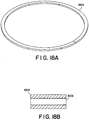
- retaining ring seal 664 preferably made of carbon steel, is shown attached to rotating assembly 53.
- the retaining seal ring 664 is preferably a split ring as shown in perspective view in Figure 18A , and has a cross-section as shown in Figure 18B . Splitting the ring facilitates installation and removal.
- the retaining seal ring 664 can be attached to the rotating assembly 53 with a cap screw 140, although other suitable means for attaching the ring 664 could be used.
- the rotating assembly includes a groove for properly positioning the retaining ring seal in place.
- Opposite retaining seal ring 664 is mounting ring 091, best seen in Figures 18C and 18D .
- the mounting ring 091 is also coupled to rotating assembly 53 with cap screw 140', and a groove for properly positioning the mounting ring 091 is formed in the rotating assembly.
- the weight of the seal ring 658 can result in wear as it slides against the mounting ring 091.
- the mounting ring 663 is formed with a tongue 401 formed along its circumference, preferably centrally located as best shown in Figure 18D .
- An optional plate-bearing arc 663 has a groove 402 ( Figures 18E, 18F ) corresponding in shape and location to the tongue 401, and seats over the mounting ring 091 when assembled as shown in Figure 18 .
- the plate-bearing arc 663 is preferably made of a material different from seal ring 658 to facilitate its function as a bearing. Suitable materials include bronze, ceramic, or other metal different from the metal used as the material for seal ring 658.
- seal ring 658 Positioned between retaining seal ring 664 and arc 663 is seal ring 658. As shown in Figures 18G and 18H , the seal ring 658 has a radial slot 403 formed throughout its circumference. At one edge of the seal ring 658, the radial slot 403 terminates in a circumferential semi-circular configuration, so that a distribution groove 145 is created when the seal ring 658 abuts against the ring seal housing 659, as shown in Figure 11 . Alternatively, more than one radial slot 403 could be used. In the embodiment shown, ring seal 658 also has a bore 404 formed in communication with and orthogonally to radial slot 403.
- seal ring 658 By pressurizing this bore 404, a counterbalance is created whereby the seal ring 658 is inhibited from moving downwardly due to its own weight. If the orientation of the valve were different, such as rotated 180°, the bore 404 could be formed in the upper portion of seal ring 658. Alternatively, more than one bore 404 could e used in the upper or lower portions, or both. If the orientation were rotated 90°, for example, no counterbalance would be necessary. Since seal ring 658 remains stationary and the housing is stationary, seal 658 need not be round; other shapes including oval and octagonal also are suitable. The ring seal 658 can be made of a single piece, or could be two or more pieces.
- the ring seal 658 biases against ring seal housing 659, and remains stationary even as the flow distributor 50 (and seal ring 664, plate bearing 663 and mounting ring 091) rotates. Pressurized air (or gas) flows through the radial ducts 83 as shown by the arrows in Figure 18 , and into the radial slot 403 and bore 404, as well as in the distribution groove 145 between the ring seal 658 and housing 659, the gap between the retaining ring seal 664 and housing 659, and the gaps between the arc 663 and housing 659 and mounting ring 091 and housing 659.
- the distribution groove 145 divides the outside surface of the ring seal 658 into three zones, with two in contact with the outer bore, and a center pressure zone.
- a single sealing ring assembly By using a single sealing ring assembly, forces which push or pull dual piston ring seals apart are eliminated. In addition, a savings is realized as the number parts are reduced, and a single ring can be made of a larger cross-section and thereby can be made from more dimensionally stable components.
- the ring can be split into two halves to allow for easier installation and replacement. Compression springs or other biasing means can be placed in recessed holes 405 ( Figure 18I ) at the split to provide outward force of the ring to the bore.
- Figure 15 illustrates how the plenum 64 feeding the shaft 52 with pressurized air is sealed against the drive shaft 52.
- the sealing is in a manner similar to the rotating port discussed above, except that the seals are not pressurized, and only one piston ring need by used for each seal above and below the plenum 64.
- a C-shaped inner ring seal 216 is formed by boring a central groove therein.
- a stationary annular cylindrical wall 210 that functions as an outer ring seal includes an outer annular flange 211 used to center the wall 210 and clamp it to the plenum 64.
- a stationary piston ring 212 sits in the groove formed in the C-shaped inner ring seal 216 and biases against the wall 210.
- a similar cylindrical wall 310, C-shaped inner seal 316 and piston ring 312 is used on the opposite side of the plenum 64 as shown in Figure 15 .
- Cool air that normally enters aperture 110 in plenum 64 housed in manifold 51 and flows into the shaft 52 through apertures 81 is instead diverted into heat exchanger 112.
- the preferred way to divert the flow of cool air is with a baffle 115 positioned in plenum 64.
- the baffle 115 extends from the floor of the plenum 64 to the ceiling of the plenum 64, thereby segregating the plenum 64 into a heat exchanger inlet section 116 and a heat exchanger outlet section 117.
- the aperture 110 is positioned entirely in the heat exchanger inlet section 116, so that cold air flowing from the aperture 110 into the plenum 64 resides only in inlet section 116 and is forced into the inlet of the heat exchanger 112 (via slots 111a, lllb) where it is heated to a temperature sufficient to minimize or prevent cooling of the process gas condensables. Suitable temperatures are those above the dew point of the process gas, generally from about 338.7°K (150°F) to about 393.4°K (250°F).
- the heated sealing air exits the heat exchanger on the opposite side of the baffle into heat exchanger outlet portion 117 of plenum 64 (via slots lllc, llld), and enters the drive shaft 52 in fluid communication with outlet section 117 of the plenum 64 in a heated state. Since the inlet section 116 is not in fluid communication with the drive shaft 52, unheated seal air cannot enter the drive shaft until it has passed through the heat exchanger.
- the drive shaft 52 acts as a fluid conduit to direct the heated seal air to the sealing surfaces.
- the heat exchanger 112 is preferably positioned in the outlet plenum 47 so that the atmosphere surrounding the heat exchanger 112 is hot exhaust air. In this way, the seal air is heated by conduction and no supplemental heat source is necessary to heat the seal air.
- the temperature of the hot exhaust air is high enough so that the heat exchanger 112 is heated to a temperature sufficient to heat the cold seal air as it flows through the heat exchanger 112. The present invention thus captures this previously wasted heat (energy) and heats the seal air without taxing the system or requiring an additional energy source.
- This particular location for the heat exchanger 112 shown in Figures 8 and 9 at the front of the plenum 47 is a convenient location amenable to easy retrofitting of existing equipment, since communication with plenum 64 is readily accomplished simply by forming heat exchange inlet and outlet holes or slots 111 (sufficient to provide fluid communication between the plenum 64 and the heat exchange tubes) in the side walls of plenum 64 as shown in Figure 12 .
- This location of the heat exchanger 112 also does not result in interference with other oxidizer peripheries, such as an entrapment chamber.
- the heat exchanger 112 could be positioned about the inner perimeter of the plenum 47, around the flow distributor 50.
- FIG 13 shows a preferred embodiment of a heat exchanger 112 suitable for use in the present invention.
- a plurality of tubes 112 (ten shown) are assembled in a configuration conducive to placement in the exhaust plenum 64.
- the preferred configuration is substantially C-shaped as shown.
- the gap between the inlet end 123 of the heat exchanger 112 and outlet end 124 of the heat exchanger 112 is sufficient to accommodate the plenum 64.
- the heat exchanger 112 is formed in two equal parts, held together after assembly by center support flange 129.
- a 40-50% efficient heat exchanger has been found to be sufficient to heat the seal air to a suitable temperature.
- Figure 14 illustrates how the plenum 64 feeding the shaft 52 with pressurized air is sealed against the drive shaft 52. Only one piston ring need by used for each seal above and below the plenum 64.
- a C-shaped inner ring seal 216 is formed by boring a central groove therein.
- a stationary annular cylindrical wall 210 that functions as an outer ring seal includes an outer annular flange 211 used to center the wall 210 and clamp it to the plenum 64.
- a stationary piston ring 212 sits in the groove formed in the C-shaped inner ring seal 216 and biases against the wall 210.
- a similar cylindrical wall 310, C-shaped inner seal 316 and piston ring 312 is used on the opposite side of the plenum 64 as shown in Figure 14 .
- untreated (“dirty”) process gas flows into inlet 48, through passageway 61 of the flow distributor 50, and into which ever respective valve ports 25 that are in open communication with the passageway 61 in this mode.
- the untreated process gas then flows up through the hot heat exchange media supported by cold face plenum 20 and through the combustion zone where it is treated, and the now clean gas is then cooled as it flows down through the cold heat exchange media in a second column, through the valve ports 25 in communication with passageway 60, and out through plenum 47 and outlet 49.
- the cycle is reversed by activating the drive mechanism to rotate drive shaft 52 and flow distributor 50.
- untreated process gas again flows into inlet 48, through passageway 61 of the flow distributor 50, which passageway is now in communication with different valve ports 25 that were previously only in fluid communication with passageway 60, thus directing the untreated process gas to the now hot heat exchange column and then through the combustion zone where the process gas is treated.
- the cleaned gas is then cooled as it flows down through the now cold heat exchange media in the other column, through the valve ports 25 now in communication with passageway 60, and out through plenum 47 and outlet 49.
- This cycle repeats itself as needed, typically every 1-4 minutes.
- the hot exhaust gas in plenum 47 surrounds the heat exchanger 112 and transfers some of its heat thereto, thereby heating the seal air circulating in the heat exchanger 112.
- the present invention is applicable to other types of valve systems, including poppet valves and butterfly valves.
- the important components are the valve, a blower or other device to deliver sealing gas, a heat exchanger in the hot exhaust stream, and a conduit from the heat exchanger to the sealing surface(s).
- a blower or other device to deliver sealing gas For example, in a two bed regenerative thermal oxidizer utilizing four poppet valves 200, 201, 202 and 203 as shown in Figure 16 , only the two valves at the column inlets require heated seal air, since the two outlet valves are already warm and condensation generally is not problematic.
- a seal air blower 210 feeds seal air through heat exchanger 212 positioned in the exhaust stream, such as in the exhaust stack 216.
- the outlet of the heat exchanger 212 is in fluid communication with the sealing surfaces of the valve through suitable delivery conduits.
- On/off valves 220, 221 are positioned in each respective conduit to stop sealing air flow to a respective poppet valve when the poppet valve is in the open position, and to allow for flow when the poppet valve is in the closed, sealed position.
- the poppet disk 230 of the poppet valve is coupled to a shaft 231 that retracts and extends the valve using cylinder 232.
- An annular plenum 240 with two seats is in fluid communication with the heated seal air as shown. When the valve is in the closed position, the heated seal air flows into the plenum and creates an effective seal.
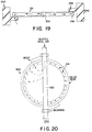
- FIG. 19 and 20 illustrate application of the present invention to butterfly valve 330.
- a cavity of a hollow blade 331 is in fluid communication with hollow shaft 332 that is coupled to a rotary actuator 344 for rotating the blade 331 into and out of sealing relationship with the valve seat 335 of valve housing 340.
- the shaft 332 is also in fluid communication with a source of heated seal air.
- the blade 331 includes a plurality of seal ports 341 about its periphery that align with valve seat 335 to create the sealed interface when the valve is in the closed position. Heated seal air flows from the shaft 332, into the blade 331, out the seal ports 341 and against the valve seat 335.
Description
- Regenerative thermal oxidizers are conventionally used for destroying volatile organic compounds (VOCs) in high flow, low concentration emissions from industrial and power plants. Such oxidizers typically require high oxidation temperatures in order to achieve high VOC destruction. To achieve high heat recovery efficiency, the "dirty" process gas that is to be treated is preheated before oxidation. A heat exchanger column is typically provided to preheat these gases. The column is usually packed with a heat exchange material having good thermal and mechanical stability and sufficient thermal mass. In operation, the process gas is fed through a previously heated heat exchanger column, which, in turn, heats the process gas to a temperature approaching or attaining its VOC oxidation temperature. This pre-heated process gas is then directed into a combustion zone where any incomplete VOC oxidation is usually completed. The treated now "clean" gas is then directed out of the combustion zone and back through the heat exchanger column, or through a second heat exchange column. As the hot oxidized gas continues through this column, the gas transfers its heat to the heat exchange media in that column, cooling the gas and pre-heating the heat exchange media so that another batch of process gas may be preheated prior to the oxidation treatment. Usually, a regenerative thermal oxidizer has at least two heat exchanger columns, which alternately receive process and treated gases. This process is continuously carried out, allowing a large volume of process gas to be efficiently treated.
- The performance of a regenerative oxidizer may be optimized by increasing VOC destruction efficiency and by reducing operating and capital costs. The art of increasing VOC destruction efficiency has been addressed in the literature using, for example, means such as improved oxidation systems and purge systems (e.g., entrapment chambers), and three or more heat exchangers to handle the untreated volume of gas within the oxidizer during switchover. Operating costs can be reduced by increasing the heat recovery efficiency, and by reducing the pressure drop across the oxidizer. Operating and capital costs may be reduced by properly designing the oxidizer and by selecting appropriate heat transfer packing materials.
- An important element of an efficient oxidizer is the valving used to switch the flow of process gas from one heat exchange column to another. Any leakage of untreated process gas through the valve system will decrease the efficiency of the apparatus. In addition, disturbances and fluctuations in the pressure and/or flow in the system can be caused during valve switchover and are undesirable. Valve wear is also problematic, especially in view of the high frequency of valve switching in regenerative thermal oxidizer applications.
- One conventional two-column design uses a single switching valve having an improved seal, as disclosed in
U.S Patent No. 6,261,092 . The valve has a seal plate that defines two chambers, each chamber being a flow port that leads to one of two regenerative beds of the oxidizer. The valve also includes a switching flow distributor that provides alternate channeling of the inlet or outlet process gas to each half of the seal plate. The valve operates between two modes: a stationary mode and a valve movement mode. In the stationary mode, a tight gas seal is used to minimize or prevent process gas leakage. The gas seal also seals during valve movement. Associated baffling minimizes or eliminates untreated process gas leakage across the valve during switchover. The use of a single valve, rather than the two or four conventionally used, significantly reduces the area that requires sealing. The geometry of the switching flow distributor reduces the distance and number of turns the process gas goes through since the flow distributor can be located close to the heat exchange beds. This reduces the volume of trapped, untreated gas during valve switching. Since the process gas passes through the same valve ports in the inlet cycle as in the outlet cycle, gas distribution to the heat exchange beds is improved. Valve switching with minimal pressure fluctuations, excellent sealing, and minimal or no bypass during switching are achieved in regenerative thermal oxidation applications. In view of the elimination of bypass during switching, the conventional entrapment chambers used to store the volume of unprocessed gas in the system during switching can be eliminated, thereby saving substantial costs. - Seal air has been used to enhance the ability for such flow control valves to direct flow into and out of regenerative thermal and catalytic oxidizers, for example. This is accomplished by using positive or negative pressurized gas directed at the seating surfaces of the valve. Typically the air used for sealing is external air at or near ambient temperature. In systems using positive pressure gas, the cooling effect of this seal air can cause deposits on the valve seat due to condensable or sticky particulate in the process gas stream. This is especially problematic in graphic arts applications, where the presence of condensables is common in the process gas.
- It therefore would be desirable to reduce or eliminate the condensation of substances in such oxidizers. Document
US5871349 discloses a rotary valve thermal oxidizer including an interfacial seal disposed between rotating and fixed valve portions. The valve sealing device includes a flowable sealing material and may include as well purge and/or sealing gases. DocumentUS6039927 discloses a poppet valves assembly used in a chamber regenerative thermal oxidizer. DocumentUS3368611 discloses a rotary regenerator with a heat exchanger for heating a second gas with a source of hot gas. - The problems of the prior art have been overcome by the present invention, which provides a gas seal for a switching valve. The seal of the present invention utilizes gas, preferably air, that is at a sufficiently high temperature to minimize or eliminate condensation of substances that would otherwise condense as a result of being cooled by the sealing gas. The sealing gas is heated by heat exchange with exhaust air from the regenerative thermal oxidizer, thereby providing a cost-effective solution to deleterious condensation. Strategic location of the heat exchanger for heating the sealing gas allows for compact construction and simplicity in retrofitting the heat exchanger into existing units. Reference (s) to "embodiment (s)" throughout the description which are not under the scope of the appended claims merely represent possible exemplary executions and are therefore not part of the present invention.
-
-
Figure 1 is a perspective view of a regenerative thermal oxidizer in accordance with one embodiment of the present invention; -
Figure 2 is a perspective exploded view of a portion of a regenerative thermal oxidizer in accordance with one embodiment of the present invention; -
Figure 3 is a bottom perspective view of valve ports forming part of a valve suitable for use with the present invention; -
Figure 4 is a perspective view of a flow distributor forming part of a switching valve suitable for use with the present invention; -
Figure 4A is a cross-sectional view of the flow distributor ofFigure 4 ; -
Figure 5 is a perspective view of a portion of the flow distributor ofFigure 4 ; -
Figure 6 is a top view of the seal plate of a valve suitable for use with the present invention; -
Figure 6A is a cross-sectional view of a portion of the seal plate ofFigure 6 ; -
Figure 7 is a perspective view of the shaft of the flow distributor ofFigure 4 ; -
Figure 8 is a top view of the heat exchanger positioned in the outlet gas plenum in accordance with the present invention; -
Figure 9 is a top view of the sealing gas plenum with the heat exchanger removed for clarity, in accordance with the present invention; -
Figure 10 is a front view of the gas outlet plenum and sealing gas plenum in accordance with the present invention; -
Figure 11 is a cross-sectional view of the flow distributor and of the heat exchanger in the gas outlet plenum in accordance with an embodiment of the present invention; -
Figure 12 is a perspective view of the baffle in the sealing gas plenum in accordance with the present invention; -
Figure 13 is a perspective view of the heat exchanger in accordance with the present invention; -
Figure 14 is a cross-sectional view of the rotating port of a flow distributor suitable for use with the present invention; -
Figure 15 is a cross-sectional view of the lower portion of the drive shaft of the flow distributor suitable for use with the present invention; -
Figure 16 is a schematic view of a regenerative thermal oxidizer using poppet valves with heated seal air in accordance with an embodiment of the present invention; -
Figure 17 is a schematic view of the annular sealing interface for a poppet valve in accordance with an embodiment of the present invention -
Figure 18 is a cross-sectional view of the rotating port of a valve suitable for use with the present invention; -
Figure 18A is a perspective view of the retaining ring for sealing a valve suitable for use with the present invention; -
Figure 18B is a cross-sectional view of the retaining ring ofFigure 18A ; -
Figure 18C is a perspective view of the mounting ring for sealing a valve suitable for use with the present invention; -
Figure 18D is a cross-sectional view of the mounting ring ofFigure 18C ; -
Figure 18E is a perspective view of the plate bearing arc for valve suitable for use with the present invention; -
Figure 18F is a cross-sectional view of the plate bearing arc ofFigure 18E ; -
Figure 18G is a perspective view of one embodiment of the seal ring for a valve suitable for use with the present invention; -
Figure 18H is a cross-sectional view of the seal ring ofFigure 18G ; -
Figure 18I is a cross-sectional view of the recess in the seal ring ofFigure 18G ; -
Figure 19 is a sectional view of a butterfly valve utilizing heated seal air in accordance with an embodiment of the present invention; and -
Figure 20 is a top view of the butterfly valve ofFigure 19 . - Although the majority of the following description illustrates the use of heated sealing gas in the context of the switching valve of
U.S. Patent No. 6,261,092 , it is noted that the invention is not intended to be limited to any particular valve and can be employed in any valve system that includes a source of heat. - Familiarity with the valve disclosed in the '092 patent is assumed. Briefly,
Figures 1 and2 show a two-chamber regenerative thermal oxidizer 10 (catalytic or non-catalytic) supported on aframe 12 as shown. Theoxidizer 10 includeshousing 15 in which there are first and second heat exchanger chambers in communication with a centrally located combustion zone. A burner (not shown) may be associated with the combustion zone, and a combustion blower may be supported on theframe 12 to supply combustion air to the burner. The combustion zone includes abypass outlet 14 in fluid communication withexhaust stack 16 typically leading to atmosphere. A control cabinet 11 houses the controls for the apparatus and is also preferably located onframe 12. Opposite control cabinet 11 is a fan (not shown) supported onframe 12 for driving the process gas into theoxidizer 10.Housing 15 includes a top chamber orroof 17 having one ormore access doors 18 providing operator access into thehousing 15. Those skilled in the art will appreciate that the foregoing description of the oxidizer is for illustrative purposes only; other designs are well within the scope of the present invention, including oxidizers with more or less than two chambers, oxidizers with horizontally oriented chamber(s), and catalytic oxidizers. Acold face plenum 20 forms the base ofhousing 15 as best seen inFigure 2 . Suitable support grating 19 is provided on thecold face plenum 20 and supports the heat exchange matrix in each heat exchange column as is discussed in greater detail below. In the embodiment shown, the heat exchange chambers are separated byseparation walls 21, which are preferably insulated. Also in the embodiment shown, flow through the heat exchange beds is vertical; process gas enters the beds from the valve ports located in thecold face plenum 20, flows upwardly (towards roof 17) into a first bed, enters the combustion zone in communication with the first bed, flows out of the combustion zone and into a second chamber, where it flows downwardly through a second bed towards thecold face plenum 20. However, those skilled in the art will appreciate that other orientations are suitable including a horizontal arrangement, such as one where the heat exchange columns face each other and are separated by a centrally located combustion zone. -
Figure 3 is a view of the valve ports 25 from the bottom.Plate 28 has two oppositesymmetrical openings Figure 2 ), define the valve ports 25. Situated in each valve port 25 is anoptional turn vane 27. Eachturn vane 27 has a first end secured to theplate 28, and a second end spaced from the first end secured to the baffle 24 on each side. Eachturn vane 27 widens from its first end toward its second end, and is angled upwardly at an angle and then flattens to horizontal at 27A as shown inFigure 4 . The turn vanes 27 act to direct the flow of process gas emanating from the valve ports away from the valve ports to assist in distribution across the cold face plenum during operation. Uniform distribution into thecold face plenum 20 helps ensure uniform distribution through the heat exchange media for optimum heat exchange efficiency. -
Figures 4 and 4A show theflow distributor 50 contained in a manifold 51 having aprocess gas inlet 48 and a process gas outlet 49 (althoughelement 48 could be the outlet and 49 the inlet, for purposes of illustration the former embodiment will be used herein). Theflow distributor 50 includes a preferably hollow cylindrical drive shaft 52 (Figures 4A ,6 ) that is coupled to a drive mechanism. Coupled to thedrive shaft 52 is a partial frusto-conically shapedmember 53. Themember 53 includes a mating plate formed of two opposite pie-shaped sealing surfaces 55, 56, each connected by circularouter edge 54 and extending outwardly from thedrive shaft 52 at an angle of 45°, such that the void defined by the two sealingsurfaces outer edge 54 defines a first gas route orpassageway 60. Similarly, a second gas route orpassageway 61 is defined by the sealing surfaces 55, 56 opposite the first passageway, and three angled side plates, namely, oppositeangled side plates angled side plate 57C. The angled side plates 57separate passageway 60 frompassageway 61. The top of thesepassageways symmetrical openings plate 28, and in the assembled condition, eachpassageway respective openings Passageway 61 is in fluid communication withonly inlet 48, andpassageway 60 is in fluid communication withonly outlet 49 viaplenum 47, regardless of the orientation of theflow distributor 50 at any given time. Thus, process gas entering the manifold 51 throughinlet 48 flows throughonly passageway 61, and processgas entering passageway 60 from the valve ports 25 flows only throughoutlet 49 viaplenum 47. - A sealing plate 100 (
Figure 6 ) is coupled to theplate 28 defining the valve ports 25 (Figure 3 ). Preferably an air seal is used between the top surface of theflow distributor 50 and theseal plate 100, as discussed in greater detail below. The flow distributor is rotatable about a vertical axis, viadrive shaft 52, with respect to thestationary plate 28. Such rotation moves the sealing surfaces 55, 56 into and out of blocking alignment with portions ofopenings - The method for sealing the valve will now be discussed first with reference to
Figures 4 ,6 and7 . Theflow distributor 50 rides on a cushion of air, in order to minimize or eliminate wear as the flow distributor moves. Those skilled in the art will appreciate that gases other than air could be used, although air is preferred and will be referred to herein for purposes of illustration. A cushion of air not only seals the valve, but also results in frictionless or substantially frictionless flow distributor movement. A pressurized delivery system, such as a fan or the like, which can be the same or different from the fan used to supply the combustion air to the combustion zone burner, supplies air to thedrive shaft 52 of theflow distributor 50 via suitable ducting (not shown) andplenum 64. As best seen inFigure 7 , the air travels from the ducting into thedrive shaft 52 via one ormore apertures 81 formed in the body of thedrive shaft 52 above the base 82 of thedrive shaft 52 that is coupled to the drive mechanism 70. The exact location of the apertures (s) 81 is not particularly limited, although preferably theapertures 18 are symmetrically located about theshaft 52 and are equally sized for uniformity. The pressurized air flows up the shaft as depicted by the arrows inFigure 5 , and a portion enters on or moreradial ducts 83 which communicate with and feed a ring seal located at the annularrotating port 90 as discussed in greater detail below. A portion of the air that does not enter theradial ducts 83 continues up thedrive shaft 52 until it reachespassageways 94, which distribute the air in a channel having asemi-annular portion 95 and a portion defined by the pie-shapedwedges flow distributor 50, in particular, the mating surfaces of pie-shapedwedges annular edge 54, are formed with a plurality ofapertures 96 as shown inFigure 4 . The pressurized air fromchannel 95 escapes fromchannel 95 through theseapertures 96 as shown by the arrows inFigure 5 , and creates a cushion of air between the top surface of theflow distributor 50 and astationary seal plate 100 shown inFigure 6 . Theseal plate 100 includes an annularouter edge 102 having a width corresponding to the width of thetop surface 54 of theflow distributor 50, and a pair of pie-shapedelements wedges flow distributor 50. It matches (and is coupled to) plate 28 (Figure 3 ) of the valve port.Aperture 104 receives shaft pin 59 (Figure 5 ) coupled to theflow distributor 50. The underside of the annularouter edge 102 facing the flow distributor includes one or more annular grooves 99 (Figure 6A ) which align with theapertures 96 in the mating surface of theflow distributor 50. Preferably there are two concentric rows ofgrooves 99, and two corresponding rows ofapertures 96. Thus, thegrooves 99 aid in causing the air escaping fromapertures 96 in thetop surface 54 to form a cushion of air between themating surface 54 and the annularouter edge 102 of theseal plate 100. In addition, the air escaping theapertures 96 in the pie-shapedportions portions portions seal plate 100. These cushions of air minimize or prevent leakage of the process gas that has not been cleaned into the flow of clean process gas. The relatively large pie-shaped wedges of both theflow distributor 50 and theseal plate 100 provide a long path across the top of theflow distributor 50 that uncleaned gas would have to traverse in order to cause leakage. Since the flow distributor is stationary the majority of time during operation, an impenetrable cushion of air is created between all of the valve mating surfaces. When the flow distributor is required to move, the cushion of air used to seal the valve now also functions to eliminate any high contact pressures from creating wear between theflow distributor 50 and theseal plate 100. - Preferably the pressurized air is delivered from a fan different from that delivering the process gas to the apparatus in which the valve is used, so that the pressure of the sealing air is higher than the inlet or outlet process gas pressure, thereby providing a positive seal.
- The
flow distributor 50 includes a rotating port as best seen inFigures 7 and14 . The frusto-conical section 53 of theflow distributor 50 rotates about an annularcylindrical wall 110 that functions as an outer ring seal. Thewall 110 includes an outerannular flange 111 used to center thewall 110 and clamp it to the manifold 51 (see alsoFigure 4 ). An E-shaped inner ring seal member 116 (preferably made of metal) is coupled to theflow distributor 50 and has a pair of spacedparallel grooves Piston ring 112A sits ingroove 115A, andpiston ring 112B sits ingroove 115B as shown. Eachpiston ring 112 biases against the outerring seal wall 110, and remains stationary even as theflow distributor 50 rotates. Pressurized air (or gas) flows through theradial ducts 83 as shown by the arrows inFigure 14 , throughapertures 84 communicating with eachradial duct 83, and into thechannel 119 between thepiston rings piston ring 112 and theinner ring seal 116. As the flow distributor rotates with respect to stationary cylindrical wall 110 (and thepiston rings channel 119 pressurizes the space between the twopiston rings inner piston seal 116, and thegap 85 between theinner piston seal 116 and thewall 110, accommodate any movement (axial or otherwise) in thedrive shaft 52 due to thermal growth or other factors. Those skilled in the art will appreciate that although a dual piston ring seal is shown, three or more piston rings also could be employed for further sealing. Positive or negative pressure can be used to seal. -
Figure 15 illustrates how theplenum 64 feeding theshaft 52 with pressurized air is sealed against thedrive shaft 52. The sealing is in a manner similar to the rotating port discussed above, except that the seals are not pressurized, and only one piston ring need by used for each seal above and below theplenum 64. Using the seal above theplenum 64 as exemplary, a C-shapedinner ring seal 216 is formed by boring a central groove therein. A stationary annularcylindrical wall 210 that functions as an outer ring seal includes an outerannular flange 211 used to center thewall 210 and clamp it to theplenum 64. Astationary piston ring 212 sits in the groove formed in the C-shapedinner ring seal 216 and biases against thewall 210. The gap between thepiston ring 212 and the bore of the C-shapedinner seal 216, as well as the gap between the C-shapedinner seal 216 and the outercylindrical wall 210, accommodates any movement of thedrive shaft 52 due to thermal expansion or the like. A similarcylindrical wall 310, C-shapedinner seal 316 andpiston ring 312 is used on the opposite side of theplenum 64 as shown inFigure 15 . - An alternative embodiment for sealing is shown in
Figures 18-18I and is as shown in co-pendingU.S. Patent Application Serial No. 09/849,785 . Turning toFigure 18 , retainingring seal 664, preferably made of carbon steel, is shown attached to rotatingassembly 53. The retainingseal ring 664 is preferably a split ring as shown in perspective view inFigure 18A , and has a cross-section as shown inFigure 18B . Splitting the ring facilitates installation and removal. The retainingseal ring 664 can be attached to the rotatingassembly 53 with a cap screw 140, although other suitable means for attaching thering 664 could be used. Preferably, the rotating assembly includes a groove for properly positioning the retaining ring seal in place. - Opposite retaining
seal ring 664 is mountingring 091, best seen inFigures 18C and 18D . The mountingring 091 is also coupled to rotatingassembly 53 with cap screw 140', and a groove for properly positioning the mountingring 091 is formed in the rotating assembly. - In the embodiment shown, where the rotating assembly rotates about a vertical axis, the weight of the
seal ring 658 can result in wear as it slides against the mountingring 091. In order to reduce or eliminate this wear, the mountingring 663 is formed with atongue 401 formed along its circumference, preferably centrally located as best shown inFigure 18D . An optional plate-bearingarc 663 has a groove 402 (Figures 18E, 18F ) corresponding in shape and location to thetongue 401, and seats over the mountingring 091 when assembled as shown inFigure 18 . The plate-bearingarc 663 is preferably made of a material different fromseal ring 658 to facilitate its function as a bearing. Suitable materials include bronze, ceramic, or other metal different from the metal used as the material forseal ring 658. - Positioned between retaining
seal ring 664 andarc 663 isseal ring 658. As shown inFigures 18G and 18H , theseal ring 658 has aradial slot 403 formed throughout its circumference. At one edge of theseal ring 658, theradial slot 403 terminates in a circumferential semi-circular configuration, so that adistribution groove 145 is created when theseal ring 658 abuts against thering seal housing 659, as shown inFigure 11 . Alternatively, more than oneradial slot 403 could be used. In the embodiment shown,ring seal 658 also has abore 404 formed in communication with and orthogonally toradial slot 403. By pressurizing thisbore 404, a counterbalance is created whereby theseal ring 658 is inhibited from moving downwardly due to its own weight. If the orientation of the valve were different, such as rotated 180°, thebore 404 could be formed in the upper portion ofseal ring 658. Alternatively, more than onebore 404 could e used in the upper or lower portions, or both. If the orientation were rotated 90°, for example, no counterbalance would be necessary. Sinceseal ring 658 remains stationary and the housing is stationary,seal 658 need not be round; other shapes including oval and octagonal also are suitable. Thering seal 658 can be made of a single piece, or could be two or more pieces. - The
ring seal 658 biases againstring seal housing 659, and remains stationary even as the flow distributor 50 (andseal ring 664, plate bearing 663 and mounting ring 091) rotates. Pressurized air (or gas) flows through theradial ducts 83 as shown by the arrows inFigure 18 , and into theradial slot 403 and bore 404, as well as in thedistribution groove 145 between thering seal 658 andhousing 659, the gap between the retainingring seal 664 andhousing 659, and the gaps between thearc 663 andhousing 659 and mountingring 091 andhousing 659. As the flow distributor rotates with respect to stationary housing 659 (and the stationary seal ring 658), the air in these gaps pressurizes these spaces creating a continuous and non-friction seal. Thedistribution groove 145 divides the outside surface of thering seal 658 into three zones, with two in contact with the outer bore, and a center pressure zone. - By using a single sealing ring assembly, forces which push or pull dual piston ring seals apart are eliminated. In addition, a savings is realized as the number parts are reduced, and a single ring can be made of a larger cross-section and thereby can be made from more dimensionally stable components. The ring can be split into two halves to allow for easier installation and replacement. Compression springs or other biasing means can be placed in recessed holes 405 (
Figure 18I ) at the split to provide outward force of the ring to the bore. -
Figure 15 illustrates how theplenum 64 feeding theshaft 52 with pressurized air is sealed against thedrive shaft 52. The sealing is in a manner similar to the rotating port discussed above, except that the seals are not pressurized, and only one piston ring need by used for each seal above and below theplenum 64. Using the seal above theplenum 64 as exemplary, a C-shapedinner ring seal 216 is formed by boring a central groove therein. A stationary annularcylindrical wall 210 that functions as an outer ring seal includes an outerannular flange 211 used to center thewall 210 and clamp it to theplenum 64. Astationary piston ring 212 sits in the groove formed in the C-shapedinner ring seal 216 and biases against thewall 210. The gap between thepiston ring 212 and the bore of the C-shapedinner seal 216, as well as the gap between the C-shapedinner seal 216 and the outercylindrical wall 210, accommodates any movement of thedrive shaft 52 due to thermal expansion or the like. A similarcylindrical wall 310, C-shapedinner seal 316 andpiston ring 312 is used on the opposite side of theplenum 64 as shown inFigure 15 . - Turning now to
Figures 8 and 9 , the preferred embodiment for heating the sealing air is illustrated. Cool air that normally entersaperture 110 inplenum 64 housed inmanifold 51 and flows into theshaft 52 throughapertures 81 is instead diverted intoheat exchanger 112. With particular reference toFigures 9 and12 , the preferred way to divert the flow of cool air is with abaffle 115 positioned inplenum 64. Thebaffle 115 extends from the floor of theplenum 64 to the ceiling of theplenum 64, thereby segregating theplenum 64 into a heatexchanger inlet section 116 and a heatexchanger outlet section 117. Theaperture 110 is positioned entirely in the heatexchanger inlet section 116, so that cold air flowing from theaperture 110 into theplenum 64 resides only ininlet section 116 and is forced into the inlet of the heat exchanger 112 (via slots 111a, lllb) where it is heated to a temperature sufficient to minimize or prevent cooling of the process gas condensables. Suitable temperatures are those above the dew point of the process gas, generally from about 338.7°K (150°F) to about 393.4°K (250°F). The heated sealing air exits the heat exchanger on the opposite side of the baffle into heatexchanger outlet portion 117 of plenum 64 (via slots lllc, llld), and enters thedrive shaft 52 in fluid communication withoutlet section 117 of theplenum 64 in a heated state. Since theinlet section 116 is not in fluid communication with thedrive shaft 52, unheated seal air cannot enter the drive shaft until it has passed through the heat exchanger. Thedrive shaft 52 acts as a fluid conduit to direct the heated seal air to the sealing surfaces. - The
heat exchanger 112 is preferably positioned in theoutlet plenum 47 so that the atmosphere surrounding theheat exchanger 112 is hot exhaust air. In this way, the seal air is heated by conduction and no supplemental heat source is necessary to heat the seal air. The temperature of the hot exhaust air is high enough so that theheat exchanger 112 is heated to a temperature sufficient to heat the cold seal air as it flows through theheat exchanger 112. The present invention thus captures this previously wasted heat (energy) and heats the seal air without taxing the system or requiring an additional energy source. This particular location for theheat exchanger 112 shown inFigures 8 and 9 at the front of theplenum 47 is a convenient location amenable to easy retrofitting of existing equipment, since communication withplenum 64 is readily accomplished simply by forming heat exchange inlet and outlet holes or slots 111 (sufficient to provide fluid communication between theplenum 64 and the heat exchange tubes) in the side walls ofplenum 64 as shown inFigure 12 . This location of theheat exchanger 112 also does not result in interference with other oxidizer peripheries, such as an entrapment chamber. Alternatively, theheat exchanger 112 could be positioned about the inner perimeter of theplenum 47, around theflow distributor 50. -
Figure 13 shows a preferred embodiment of aheat exchanger 112 suitable for use in the present invention. A plurality of tubes 112 (ten shown) are assembled in a configuration conducive to placement in theexhaust plenum 64. The preferred configuration is substantially C-shaped as shown. The gap between theinlet end 123 of theheat exchanger 112 and outlet end 124 of theheat exchanger 112 is sufficient to accommodate theplenum 64. For ease of assembly, preferably theheat exchanger 112 is formed in two equal parts, held together after assembly bycenter support flange 129. A 40-50% efficient heat exchanger has been found to be sufficient to heat the seal air to a suitable temperature. -
Figure 14 illustrates how theplenum 64 feeding theshaft 52 with pressurized air is sealed against thedrive shaft 52. Only one piston ring need by used for each seal above and below theplenum 64. Using the seal above theplenum 64 as exemplary, a C-shapedinner ring seal 216 is formed by boring a central groove therein. A stationary annularcylindrical wall 210 that functions as an outer ring seal includes an outerannular flange 211 used to center thewall 210 and clamp it to theplenum 64. Astationary piston ring 212 sits in the groove formed in the C-shapedinner ring seal 216 and biases against thewall 210. The gap between thepiston ring 212 and the bore of the C-shapedinner seal 216, as well as the gap between the C-shapedinner seal 216 and the outercylindrical wall 210, accommodates any movement of thedrive shaft 52 due to thermal expansion or the like. A similarcylindrical wall 310, C-shapedinner seal 316 andpiston ring 312 is used on the opposite side of theplenum 64 as shown inFigure 14 . - In operation, in a first mode, untreated ("dirty") process gas flows into
inlet 48, throughpassageway 61 of theflow distributor 50, and into which ever respective valve ports 25 that are in open communication with thepassageway 61 in this mode. The untreated process gas then flows up through the hot heat exchange media supported bycold face plenum 20 and through the combustion zone where it is treated, and the now clean gas is then cooled as it flows down through the cold heat exchange media in a second column, through the valve ports 25 in communication withpassageway 60, and out throughplenum 47 andoutlet 49. Once the cold heat exchange media becomes relatively hot and the hot heat exchange media becomes relatively cold, the cycle is reversed by activating the drive mechanism to rotatedrive shaft 52 andflow distributor 50. In this second mode, untreated process gas again flows intoinlet 48, throughpassageway 61 of theflow distributor 50, which passageway is now in communication with different valve ports 25 that were previously only in fluid communication withpassageway 60, thus directing the untreated process gas to the now hot heat exchange column and then through the combustion zone where the process gas is treated. The cleaned gas is then cooled as it flows down through the now cold heat exchange media in the other column, through the valve ports 25 now in communication withpassageway 60, and out throughplenum 47 andoutlet 49. This cycle repeats itself as needed, typically every 1-4 minutes. The hot exhaust gas inplenum 47 surrounds theheat exchanger 112 and transfers some of its heat thereto, thereby heating the seal air circulating in theheat exchanger 112. - As stated above, the present invention is applicable to other types of valve systems, including poppet valves and butterfly valves. The important components are the valve, a blower or other device to deliver sealing gas, a heat exchanger in the hot exhaust stream, and a conduit from the heat exchanger to the sealing surface(s). For example, in a two bed regenerative thermal oxidizer utilizing four
poppet valves Figure 16 , only the two valves at the column inlets require heated seal air, since the two outlet valves are already warm and condensation generally is not problematic. Aseal air blower 210 feeds seal air throughheat exchanger 212 positioned in the exhaust stream, such as in theexhaust stack 216. The outlet of theheat exchanger 212 is in fluid communication with the sealing surfaces of the valve through suitable delivery conduits. On/offvalves 220, 221 are positioned in each respective conduit to stop sealing air flow to a respective poppet valve when the poppet valve is in the open position, and to allow for flow when the poppet valve is in the closed, sealed position. - As best seen in
Figure 17 , thepoppet disk 230 of the poppet valve is coupled to ashaft 231 that retracts and extends thevalve using cylinder 232. Anannular plenum 240 with two seats is in fluid communication with the heated seal air as shown. When the valve is in the closed position, the heated seal air flows into the plenum and creates an effective seal. - Similarly,
Figures 19 and 20 illustrate application of the present invention tobutterfly valve 330. A cavity of ahollow blade 331 is in fluid communication withhollow shaft 332 that is coupled to arotary actuator 344 for rotating theblade 331 into and out of sealing relationship with thevalve seat 335 ofvalve housing 340. Theshaft 332 is also in fluid communication with a source of heated seal air. Theblade 331 includes a plurality ofseal ports 341 about its periphery that align withvalve seat 335 to create the sealed interface when the valve is in the closed position. Heated seal air flows from theshaft 332, into theblade 331, out theseal ports 341 and against thevalve seat 335.
Claims (13)
- A valve assembly, comprising: a source of sealing gas; a source of hot gas having a temperature higher than the temperature of said sealing gas; a heat exchanger (112) having an inlet (116) and an outlet (117), said inlet being in fluid communication with said source of sealing gas such that said sealing gas enters said inlet (116), flows through said heat exchanger (112) and exits said outlet (117), said sealing gas being heated while flowing through said heat exchanger (112), said heat exchanger (112) being heated by said hot gas; a valve including at least one sealing interface (54, 55, 56); and a delivery conduit (52) in fluid communication with said outlet (117) of said heat exchanger (112) and with said at least one sealing interface (54, 55,56) to deliver said heated sealing gas to said interface (54, 55,56).
- The valve assembly of claim 1, wherein said sealing gas is air.
- The valve assembly of claim 1, wherein said sealing gas is heated to a temperature of from about 338.7 K (150°F) to about 394.3 K (250 °F) in said heat exchanger (112).
- The valve assembly of claim 1, wherein said valve is a poppet valve.
- The valve assembly of claim 4, further comprising at least one delivery conduit valve for controlling the flow of sealing gas to said sealing interface based upon the position of said poppet valve.
- The valve assembly of claim 1, wherein said valve is a butterfly valve.
- The valve assembly of claim 1, wherein said valve comprises : a flow distributor (50) having a first passageway(61) adapted to be in fluid communication with a gas inlet (48) and a second passageway (60) adapted to be in fluid communication with a gas outlet (49), said gas outlet comprising a gas outlet compartment containing said hot gas; wherein said heat exchanger (112) is positioned in said gas outlet compartment so as to be heated by said hot gas, and wherein said sealing gas flows through said heated heat exchanger prior to entering said delivery conduit (52).
- The valve assembly of claim 7, wherein said delivery conduit comprises a hollow shaft (52) coupled to said flow distributor (50).
- The valve assembly of claim 7, wherein said sealing gas is air.
- The valve assembly of claim 7, further comprising a sealing gas plenum (64) in fluid communication with said source of sealing gas, and wherein said sealing gas plenum (64) is divided into a first inlet section (116) in fluid communication with said heat exchanger inlet and a second section (117) in fluid communication with said heat exchanger outlet, and wherein said second section is in fluid communication with said delivery conduit (52).
- The valve assembly of claim 10, wherein said sealing gas plenum (64) is divided by a baffle (115).
- The valve assembly of claim 1, wherein said heat exchanger (112) comprises a plurality of tubes.
- The valve assembly of claim 7, wherein said sealing gas is heated to a temperature of from about 338.7 K (150°F) to about 394.3 K (250°F) in said heat exchanger.
Applications Claiming Priority (3)
| Application Number | Priority Date | Filing Date | Title |
|---|---|---|---|
| US139927 | 2002-05-07 | ||
| US10/139,927 US7325562B2 (en) | 2002-05-07 | 2002-05-07 | Heated seal air for valve and regenerative thermal oxidizer containing same |
| PCT/US2003/009306 WO2003095921A1 (en) | 2002-05-07 | 2003-03-25 | Heated seal air for valve and regenerative thermal oxidizer containing same |
Publications (3)
| Publication Number | Publication Date |
|---|---|
| EP1502065A1 EP1502065A1 (en) | 2005-02-02 |
| EP1502065A4 EP1502065A4 (en) | 2016-11-09 |
| EP1502065B1 true EP1502065B1 (en) | 2020-03-18 |
Family
ID=29418377
Family Applications (1)
| Application Number | Title | Priority Date | Filing Date |
|---|---|---|---|
| EP03750024.6A Expired - Lifetime EP1502065B1 (en) | 2002-05-07 | 2003-03-25 | Heated seal air for valve assembly |
Country Status (8)
| Country | Link |
|---|---|
| US (1) | US7325562B2 (en) |
| EP (1) | EP1502065B1 (en) |
| JP (2) | JP4431490B2 (en) |
| AU (1) | AU2003226019B2 (en) |
| CA (3) | CA2712353A1 (en) |
| MX (1) | MXPA04010916A (en) |
| PL (1) | PL202601B1 (en) |
| WO (1) | WO2003095921A1 (en) |
Families Citing this family (9)
| Publication number | Priority date | Publication date | Assignee | Title |
|---|---|---|---|---|
| JP4953076B2 (en) * | 2007-06-27 | 2012-06-13 | 新東工業株式会社 | Method and apparatus for heating piston rod part of cylinder in exhaust gas purification equipment |
| US20110061576A1 (en) | 2009-09-14 | 2011-03-17 | Richard Greco | Four-way valve |
| WO2011149635A1 (en) | 2010-05-28 | 2011-12-01 | Exxonmobil Chemical Patents Inc. | Reactor with reactor head and integrated valve |
| WO2011149640A1 (en) | 2010-05-28 | 2011-12-01 | Exxonmobil Upstream Research Company | Integrated adsorber head and valve design and swing adsorption methods related thereto |
| DE102010048308B4 (en) * | 2010-10-14 | 2016-06-16 | Ctp Chemisch Thermische Prozesstechnik Gmbh | Device for cleaning polluted exhaust gas |
| WO2012118757A1 (en) | 2011-03-01 | 2012-09-07 | Exxonmobil Upstream Research Company | Apparatus and systems having a reciprocating valve head assembly and swing adsorption processes related thereto |
| KR101598196B1 (en) * | 2015-03-31 | 2016-02-29 | (주)지앤씨 | Regenerative oxidizer system |
| US11181267B2 (en) * | 2019-12-10 | 2021-11-23 | Dustex Llc | Regenerative oxidizer arrangement |
| BE1028163B1 (en) * | 2020-03-25 | 2021-10-25 | Ventil Valves Control | Shut-off valve for closing a flue gas pipe |
Family Cites Families (73)
| Publication number | Priority date | Publication date | Assignee | Title |
|---|---|---|---|---|
| US2219994A (en) | 1937-09-24 | 1940-10-29 | Bbc Brown Boveri & Cie | Gas turbine plant and regulating system therefor |
| US2898202A (en) | 1955-10-24 | 1959-08-04 | Oxy Catalyst Inc | Gas treating apparatus |
| US2946651A (en) | 1956-08-09 | 1960-07-26 | Oxy Catalyst Inc | Catalytic treatment of gas streams |
| US3368611A (en) * | 1967-07-21 | 1968-02-13 | Gen Motors Corp | Rotary regenerator seal with high pressure fluid recovery |
| DE1946436C3 (en) | 1969-05-31 | 1974-04-25 | Ansaldo Meccanico-Nucleare S.P.A., Genua (Italien) | Regenerative heat exchanger |
| DE2116728A1 (en) | 1971-04-06 | 1972-10-19 | Rothemuehle Brandt Kritzler | Regenerative air preheater with stationary regenerative chamber and rotatable cold end part |
| US4256171A (en) | 1979-02-05 | 1981-03-17 | General Motors Corporation | Regenerator seal hub gas passages |
| US4280416A (en) | 1980-01-17 | 1981-07-28 | Philip Edgerton | Rotary valve for a regenerative thermal reactor |
| US4384566A (en) * | 1980-08-11 | 1983-05-24 | Smith Rodney I | Prefabricated fireplace |
| SE445776B (en) | 1981-09-09 | 1986-07-14 | Svenska Rotor Maskiner Ab | REGENERATIVE VEHICLES INCLUDING A ROTOR WITH SECTOR-SIZED ROOMS INCLUDING REGENERATOR MATERIAL |
| DE3140406C2 (en) | 1981-10-12 | 1985-03-07 | Apparatebau Rothemühle Brandt + Kritzler GmbH, 5963 Wenden | Regenerative heat exchanger for the separate heating of two parallel flows of a heat-absorbing medium by a heat-emitting medium |
| US4454826A (en) | 1982-06-23 | 1984-06-19 | Regenerative Environmental Equipment Co., Inc. | Vertical flow incinerator having regenerative heat exchange |
| JPS59157486A (en) | 1983-02-28 | 1984-09-06 | Baanaa Internatl:Kk | Rotary heat exchanger |
| GB2136553B (en) | 1983-03-11 | 1986-02-12 | British Gas Corp | Burner |
| DE3312784A1 (en) | 1983-04-09 | 1984-10-11 | Saarbergwerke AG, 6600 Saarbrücken | REGENERATIVE HEAT TRANSFER SYSTEM |
| GB8325512D0 (en) | 1983-09-23 | 1983-10-26 | Davidson & Co Ltd | Controlling seal systems |
| SE441623B (en) | 1984-06-21 | 1985-10-21 | Heed Bjoern | PROCEDURE AND DEVICE FOR COMBUSTION AND / OR DISTRIBUTION OF POLLUTANTS |
| DE3426662A1 (en) | 1984-07-19 | 1986-01-23 | Linde Ag, 6200 Wiesbaden | Regenerator unit and method for operating the same |
| US4658853A (en) | 1985-01-09 | 1987-04-21 | Regenerative Environmental Equipment Co., Inc. | Anti-leak valving system |
| DE3508553A1 (en) | 1985-03-11 | 1986-09-11 | Hüls AG, 4370 Marl | METHOD AND DEVICE FOR CATALYTICALLY CONVERTING GASES |
| JPS6274437A (en) * | 1985-09-30 | 1987-04-06 | Babcock Hitachi Kk | Method for preventing corrosion of wet type waste gas desulfurization apparatus |
| GB2206682A (en) | 1987-07-02 | 1989-01-11 | Howden James & Co Ltd | A rotary regenerative heat exchanger |
| GR1000258B (en) | 1988-05-03 | 1992-05-12 | Leonidas Dounis | Gas burner |
| DK161037C (en) | 1988-10-17 | 1991-10-28 | Haldor Topsoe As | PROCEDURE AND PLANT TO CONTINUOUSLY CLEAN AN OXYGEN GAS FOR FLAMMABLE POLLUTIONS |
| US5016547A (en) | 1990-05-04 | 1991-05-21 | Salem Industries, Inc. | Regenerative incinerator |
| US5137078A (en) | 1990-05-11 | 1992-08-11 | Borowy William J | Air heater seals |
| US5101741A (en) * | 1991-05-10 | 1992-04-07 | Jwp Air Technologies | Flow line bake-out process for incinerator |
| DE4142136C2 (en) | 1991-12-20 | 1994-07-21 | Eisenmann Kg Maschbau | Device for cleaning polluted exhaust air from industrial plants by regenerative post-combustion |
| US5460789A (en) | 1991-12-20 | 1995-10-24 | Eisenmann Maschinenbau Kg | Apparatus for purifying pollutant-containing outgoing air from industrial installations by regenerative afterburning |
| IT1259150B (en) | 1992-09-07 | 1996-03-11 | Orv Spa | PERFECTED THERMAL DESTROYER |
| DE4301748C2 (en) | 1993-01-23 | 1995-07-27 | Ltg Lufttechnische Gmbh | Regenerative reactor |
| US5376340A (en) | 1993-04-15 | 1994-12-27 | Abb Air Preheater, Inc. | Regenerative thermal oxidizer |
| SE501211C2 (en) | 1993-06-21 | 1994-12-12 | Svenska Rotor Maskiner Ab | Device for maintaining and controlling the clearance between the sector plates and the generator mass in a rotating, regenerative heat exchanger |
| ATE180325T1 (en) | 1993-07-02 | 1999-06-15 | Berndt Lindstroem | REGENERATIVE HEAT EXCHANGER |
| US5352115A (en) * | 1993-07-12 | 1994-10-04 | Durr Industries, Inc. | Regenerative thermal oxidizer with heat exchanger columns |
| DE4344750C2 (en) | 1993-12-28 | 1997-02-27 | Schueco Int Kg | Double-skin facade |
| WO1995024593A1 (en) | 1994-03-11 | 1995-09-14 | Daikin Industries, Ltd. | Change-over valve, and regenerative combustion apparatus and regenerative heat exchanger using same |
| US5538693A (en) | 1994-08-04 | 1996-07-23 | Tellkamp Systems, Inc. | Varying switching temperature set-point method for bed flow reversal for regenerative incinerator systems |
| EP0702195A3 (en) | 1994-08-17 | 1997-05-14 | Grace W R & Co | Annular air distributor for regenerative thermal oxidizers |
| US5664942A (en) | 1994-10-25 | 1997-09-09 | Abb Air Preheater, Inc. | Regenerative thermal oxidizer |
| US5562442A (en) | 1994-12-27 | 1996-10-08 | Eisenmann Corporation | Regenerative thermal oxidizer |
| US5540584A (en) | 1995-02-03 | 1996-07-30 | Cycle-Therm | Valve cam actuation system for regenerative thermal oxidizer |
| SE504008C2 (en) | 1995-02-10 | 1996-10-14 | Ljungstroem Technology Ab | Rotary, regenerative heat exchanger where the clearance between sector plate and rotor is maintained with the help of a gas cushion, and ways to operate such a heat exchanger |
| SE503962C2 (en) | 1995-02-10 | 1996-10-07 | Ljungstroem Technology Ab | Regenerative heat exchanger and a way to operate a regenerative heat exchanger |
| SE504019C2 (en) | 1995-02-24 | 1996-10-21 | Ljungstroem Technology Ab | Rotating regenerative heat exchanger and ways to control such a heat exchanger |
| SE503802C2 (en) | 1995-03-20 | 1996-09-09 | Berndt Lindstroem | Arrangement with regenerative heat exchanger |
| US5503551A (en) | 1995-06-05 | 1996-04-02 | Houston; Reagan | Rotary valve for fume incinerator |
| SE504462C2 (en) | 1995-06-08 | 1997-02-17 | Ljungstroem Technology Ab | Regenerative, rotary heat exchanger with control that prevents drag of slip shoe |
| SE506021C2 (en) | 1995-08-17 | 1997-11-03 | Svenska Rotor Maskiner Ab | Regenerative, rotary heat exchanger |
| WO1997021959A1 (en) | 1995-12-08 | 1997-06-19 | Megtec Systems Ab | A method and a device for recovery of energy from media containing combustible substances even at low concentration |
| US5634625A (en) | 1996-01-01 | 1997-06-03 | Rose Controls Corporation | Valve closure system |
| US5700433A (en) | 1996-02-21 | 1997-12-23 | Eisenmann Corporation | Rotary valve for regenerative thermal oxidizer |
| US5888063A (en) | 1996-03-07 | 1999-03-30 | Scott; Gregory J. | Method and apparatus for quick purging a multiple bed regenerative fume incinerator |
| US5837205A (en) | 1996-05-07 | 1998-11-17 | Megtec Systems, Inc. | Bypass system and method for regenerative thermal oxidizers |
| US5833938A (en) | 1996-05-20 | 1998-11-10 | Megtec Systems, Inc. | Integrated VOC entrapment system for regenerative oxidation |
| US5692892A (en) | 1996-06-12 | 1997-12-02 | Houston; Reagan | Continuous flow rotary valve for regenerative fume incinerators |
| SE517212C2 (en) | 1996-08-15 | 2002-05-07 | Air Preheater Abb | Methods and apparatus for sensing a game |
| SE517213C2 (en) | 1996-08-15 | 2002-05-07 | Air Preheater Abb | Device for a regenerative, rotary heat exchanger |
| US5692893A (en) | 1996-08-16 | 1997-12-02 | Houston; Reagan | Rotary valve for 2-bed regenerative fume incinerator |
| US6019597A (en) * | 1996-08-20 | 2000-02-01 | Martin; Gary Lee | Process for minimizing condensibles in process streams treated by thermal oxidizers |
| DE19637090C1 (en) | 1996-09-12 | 1997-12-18 | Duerr Systems Gmbh | Device for cleaning output air - raw gas - containing oxidisable hazardous material coming from industrial plant |
| DE19643821C1 (en) | 1996-10-30 | 1998-01-15 | Schedler Johannes | Gas cleaning device for combustion chamber |
| US5871347A (en) | 1997-04-01 | 1999-02-16 | Engelhard Corporation | Rotary regenerative oxidizer |
| GB9707948D0 (en) | 1997-04-19 | 1997-06-11 | Interotex Limited | Rotary heat and/or mass transfer arrangements |
| DE19716877C1 (en) | 1997-04-22 | 1998-12-10 | Schedler Johannes | Thermally-efficient incinerator plant for cost-effective destruction of volatile organic compounds contaminating air |
| JPH10306919A (en) * | 1997-05-08 | 1998-11-17 | Babcock Hitachi Kk | Heat storage type air preheater and combustion system employing the same |
| DE19738678B4 (en) | 1997-09-04 | 2004-08-26 | Ltg Lufttechnische Gmbh | Regenerative reactor |
| US5871349A (en) | 1997-10-16 | 1999-02-16 | Smith Engineering Company | Rotary valve thermal oxidizer |
| DE19747905C1 (en) | 1997-10-30 | 1999-01-28 | Chemisch Thermische Prozestech | Cleaner for pollutant bearing exhaust gases |
| US6039927A (en) | 1997-11-04 | 2000-03-21 | Greco; Richard | Valve system for regenerative thermal oxidizers |
| US6261092B1 (en) | 2000-05-17 | 2001-07-17 | Megtec Systems, Inc. | Switching valve |
| JP3583057B2 (en) * | 2000-06-06 | 2004-10-27 | 大阪ガスエンジニアリング株式会社 | Rotary heat exchanger |
| JP2002021779A (en) * | 2000-07-07 | 2002-01-23 | Babcock Hitachi Kk | Ventilator shaft seal mechanism |
-
2002
- 2002-05-07 US US10/139,927 patent/US7325562B2/en not_active Expired - Lifetime
-
2003
- 2003-03-25 MX MXPA04010916A patent/MXPA04010916A/en active IP Right Grant
- 2003-03-25 CA CA 2712353 patent/CA2712353A1/en not_active Abandoned
- 2003-03-25 WO PCT/US2003/009306 patent/WO2003095921A1/en active Application Filing
- 2003-03-25 CA CA 2712541 patent/CA2712541A1/en not_active Abandoned
- 2003-03-25 JP JP2004503873A patent/JP4431490B2/en not_active Expired - Fee Related
- 2003-03-25 PL PL371900A patent/PL202601B1/en not_active IP Right Cessation
- 2003-03-25 CA CA2478870A patent/CA2478870C/en not_active Expired - Lifetime
- 2003-03-25 AU AU2003226019A patent/AU2003226019B2/en not_active Expired
- 2003-03-25 EP EP03750024.6A patent/EP1502065B1/en not_active Expired - Lifetime
-
2009
- 2009-11-17 JP JP2009261489A patent/JP2010078317A/en active Pending
Non-Patent Citations (1)
| Title |
|---|
| None * |
Also Published As
| Publication number | Publication date |
|---|---|
| JP2010078317A (en) | 2010-04-08 |
| AU2003226019A1 (en) | 2003-11-11 |
| JP2005524811A (en) | 2005-08-18 |
| CA2478870A1 (en) | 2003-11-20 |
| CA2712353A1 (en) | 2003-11-20 |
| CA2712541A1 (en) | 2003-11-20 |
| CA2478870C (en) | 2011-06-14 |
| EP1502065A4 (en) | 2016-11-09 |
| AU2003226019B2 (en) | 2008-04-24 |
| PL202601B1 (en) | 2009-07-31 |
| MXPA04010916A (en) | 2005-01-25 |
| PL371900A1 (en) | 2005-07-11 |
| EP1502065A1 (en) | 2005-02-02 |
| JP4431490B2 (en) | 2010-03-17 |
| US20050115696A1 (en) | 2005-06-02 |
| WO2003095921A1 (en) | 2003-11-20 |
| US7325562B2 (en) | 2008-02-05 |
Similar Documents
| Publication | Publication Date | Title |
|---|---|---|
| US6261092B1 (en) | Switching valve | |
| JP2010078317A (en) | Heated seal air for regenerative thermal oxidizer equipped with valve | |
| US6749815B2 (en) | Switching valve seal | |
| US6783111B2 (en) | Dual lift system | |
| US7150446B1 (en) | Dual lift system | |
| AU2002255899A1 (en) | Switching valve seal | |
| AU2008201845B2 (en) | Heated seal air for valve and regenerative thermal oxidizer containing same |
Legal Events
| Date | Code | Title | Description |
|---|---|---|---|
| PUAI | Public reference made under article 153(3) epc to a published international application that has entered the european phase |
Free format text: ORIGINAL CODE: 0009012 |
|
| 17P | Request for examination filed |
Effective date: 20041113 |
|
| AK | Designated contracting states |
Kind code of ref document: A1 Designated state(s): AT BE BG CH CY CZ DE DK EE ES FI FR GB GR HU IE IT LI LU MC NL PT RO SE SI SK TR |
|
| AX | Request for extension of the european patent |
Extension state: AL LT LV MK |
|
| DAX | Request for extension of the european patent (deleted) | ||
| RA4 | Supplementary search report drawn up and despatched (corrected) |
Effective date: 20161007 |
|
| RIC1 | Information provided on ipc code assigned before grant |
Ipc: F23L 15/02 20060101ALI20160930BHEP Ipc: F27D 99/00 20100101ALI20160930BHEP Ipc: F16K 49/00 20060101ALI20160930BHEP Ipc: F27D 7/02 20060101ALI20160930BHEP Ipc: F27D 17/00 20060101ALI20160930BHEP Ipc: F28D 15/00 20060101AFI20160930BHEP Ipc: F23G 7/06 20060101ALI20160930BHEP |
|
| RAP1 | Party data changed (applicant data changed or rights of an application transferred) |
Owner name: BABCOCK & WILCOX MEGTEC, LLC |
|
| RAP1 | Party data changed (applicant data changed or rights of an application transferred) |
Owner name: BABCOCK & WILCOX MEGTEC, LLC |
|
| STAA | Information on the status of an ep patent application or granted ep patent |
Free format text: STATUS: EXAMINATION IS IN PROGRESS |
|
| 17Q | First examination report despatched |
Effective date: 20180823 |
|
| RIC1 | Information provided on ipc code assigned before grant |
Ipc: F16K 49/00 20060101ALI20160930BHEP Ipc: F28D 15/00 20060101AFI20160930BHEP Ipc: F27D 7/02 20060101ALI20160930BHEP Ipc: F23L 15/02 20060101ALI20160930BHEP Ipc: F27D 17/00 20060101ALI20160930BHEP Ipc: F27D 99/00 20100101ALI20160930BHEP Ipc: F23G 7/06 20060101ALI20160930BHEP |
|
| RIC1 | Information provided on ipc code assigned before grant |
Ipc: F27D 7/02 20060101ALI20160930BHEP Ipc: F23G 7/06 20060101ALI20160930BHEP Ipc: F28D 15/00 20060101AFI20160930BHEP Ipc: F27D 17/00 20060101ALI20160930BHEP Ipc: F27D 99/00 20100101ALI20160930BHEP Ipc: F23L 15/02 20060101ALI20160930BHEP Ipc: F16K 49/00 20060101ALI20160930BHEP |
|
| GRAP | Despatch of communication of intention to grant a patent |
Free format text: ORIGINAL CODE: EPIDOSNIGR1 |
|
| STAA | Information on the status of an ep patent application or granted ep patent |
Free format text: STATUS: GRANT OF PATENT IS INTENDED |
|
| INTG | Intention to grant announced |
Effective date: 20190430 |
|
| RIC1 | Information provided on ipc code assigned before grant |
Ipc: F23G 7/06 20060101ALI20190412BHEP Ipc: F27D 7/02 20060101ALI20190412BHEP Ipc: F16K 25/02 20060101AFI20190412BHEP Ipc: F27D 17/00 20060101ALI20190412BHEP Ipc: F27D 99/00 20100101ALI20190412BHEP Ipc: F23L 15/02 20060101ALI20190412BHEP |
|
| GRAJ | Information related to disapproval of communication of intention to grant by the applicant or resumption of examination proceedings by the epo deleted |
Free format text: ORIGINAL CODE: EPIDOSDIGR1 |
|
| STAA | Information on the status of an ep patent application or granted ep patent |
Free format text: STATUS: EXAMINATION IS IN PROGRESS |
|
| REG | Reference to a national code |
Ref country code: DE Ref legal event code: R079 Ref document number: 60352414 Country of ref document: DE Free format text: PREVIOUS MAIN CLASS: F28D0015000000 Ipc: F16K0049000000 |
|
| GRAP | Despatch of communication of intention to grant a patent |
Free format text: ORIGINAL CODE: EPIDOSNIGR1 |
|
| STAA | Information on the status of an ep patent application or granted ep patent |
Free format text: STATUS: GRANT OF PATENT IS INTENDED |
|
| INTC | Intention to grant announced (deleted) | ||
| RIC1 | Information provided on ipc code assigned before grant |
Ipc: F16K 49/00 20060101AFI20190903BHEP Ipc: F27D 17/00 20060101ALI20190903BHEP Ipc: F27D 7/02 20060101ALI20190903BHEP Ipc: F27D 99/00 20100101ALI20190903BHEP Ipc: F23G 7/06 20060101ALI20190903BHEP Ipc: F16K 25/02 20060101ALI20190903BHEP Ipc: F23L 15/02 20060101ALI20190903BHEP |
|
| INTG | Intention to grant announced |
Effective date: 20190923 |
|
| GRAS | Grant fee paid |
Free format text: ORIGINAL CODE: EPIDOSNIGR3 |
|
| GRAA | (expected) grant |
Free format text: ORIGINAL CODE: 0009210 |
|
| STAA | Information on the status of an ep patent application or granted ep patent |
Free format text: STATUS: THE PATENT HAS BEEN GRANTED |
|
| RAP1 | Party data changed (applicant data changed or rights of an application transferred) |
Owner name: DURR SYSTEMS, INC. |
|
| AK | Designated contracting states |
Kind code of ref document: B1 Designated state(s): AT BE BG CH CY CZ DE DK EE ES FI FR GB GR HU IE IT LI LU MC NL PT RO SE SI SK TR |
|
| REG | Reference to a national code |
Ref country code: GB Ref legal event code: FG4D |
|
| REG | Reference to a national code |
Ref country code: DE Ref legal event code: R096 Ref document number: 60352414 Country of ref document: DE |
|
| REG | Reference to a national code |
Ref country code: AT Ref legal event code: REF Ref document number: 1246282 Country of ref document: AT Kind code of ref document: T Effective date: 20200415 Ref country code: IE Ref legal event code: FG4D |
|
| REG | Reference to a national code |
Ref country code: FI Ref legal event code: FGE |
|
| REG | Reference to a national code |
Ref country code: NL Ref legal event code: MP Effective date: 20200318 |
|
| PG25 | Lapsed in a contracting state [announced via postgrant information from national office to epo] |
Ref country code: SE Free format text: LAPSE BECAUSE OF FAILURE TO SUBMIT A TRANSLATION OF THE DESCRIPTION OR TO PAY THE FEE WITHIN THE PRESCRIBED TIME-LIMIT Effective date: 20200318 Ref country code: BG Free format text: LAPSE BECAUSE OF FAILURE TO SUBMIT A TRANSLATION OF THE DESCRIPTION OR TO PAY THE FEE WITHIN THE PRESCRIBED TIME-LIMIT Effective date: 20200618 Ref country code: GR Free format text: LAPSE BECAUSE OF FAILURE TO SUBMIT A TRANSLATION OF THE DESCRIPTION OR TO PAY THE FEE WITHIN THE PRESCRIBED TIME-LIMIT Effective date: 20200619 |
|
| PG25 | Lapsed in a contracting state [announced via postgrant information from national office to epo] |
Ref country code: NL Free format text: LAPSE BECAUSE OF FAILURE TO SUBMIT A TRANSLATION OF THE DESCRIPTION OR TO PAY THE FEE WITHIN THE PRESCRIBED TIME-LIMIT Effective date: 20200318 |
|
| PG25 | Lapsed in a contracting state [announced via postgrant information from national office to epo] |
Ref country code: EE Free format text: LAPSE BECAUSE OF FAILURE TO SUBMIT A TRANSLATION OF THE DESCRIPTION OR TO PAY THE FEE WITHIN THE PRESCRIBED TIME-LIMIT Effective date: 20200318 Ref country code: SK Free format text: LAPSE BECAUSE OF FAILURE TO SUBMIT A TRANSLATION OF THE DESCRIPTION OR TO PAY THE FEE WITHIN THE PRESCRIBED TIME-LIMIT Effective date: 20200318 Ref country code: PT Free format text: LAPSE BECAUSE OF FAILURE TO SUBMIT A TRANSLATION OF THE DESCRIPTION OR TO PAY THE FEE WITHIN THE PRESCRIBED TIME-LIMIT Effective date: 20200812 Ref country code: RO Free format text: LAPSE BECAUSE OF FAILURE TO SUBMIT A TRANSLATION OF THE DESCRIPTION OR TO PAY THE FEE WITHIN THE PRESCRIBED TIME-LIMIT Effective date: 20200318 |
|
| REG | Reference to a national code |
Ref country code: CH Ref legal event code: PL |
|
| REG | Reference to a national code |
Ref country code: AT Ref legal event code: MK05 Ref document number: 1246282 Country of ref document: AT Kind code of ref document: T Effective date: 20200318 |
|
| REG | Reference to a national code |
Ref country code: DE Ref legal event code: R097 Ref document number: 60352414 Country of ref document: DE |
|
| REG | Reference to a national code |
Ref country code: BE Ref legal event code: MM Effective date: 20200331 |
|
| PG25 | Lapsed in a contracting state [announced via postgrant information from national office to epo] |
Ref country code: MC Free format text: LAPSE BECAUSE OF FAILURE TO SUBMIT A TRANSLATION OF THE DESCRIPTION OR TO PAY THE FEE WITHIN THE PRESCRIBED TIME-LIMIT Effective date: 20200318 Ref country code: LU Free format text: LAPSE BECAUSE OF NON-PAYMENT OF DUE FEES Effective date: 20200325 |
|
| PLBE | No opposition filed within time limit |
Free format text: ORIGINAL CODE: 0009261 |
|
| STAA | Information on the status of an ep patent application or granted ep patent |
Free format text: STATUS: NO OPPOSITION FILED WITHIN TIME LIMIT |
|
| PG25 | Lapsed in a contracting state [announced via postgrant information from national office to epo] |
Ref country code: IT Free format text: LAPSE BECAUSE OF FAILURE TO SUBMIT A TRANSLATION OF THE DESCRIPTION OR TO PAY THE FEE WITHIN THE PRESCRIBED TIME-LIMIT Effective date: 20200318 Ref country code: LI Free format text: LAPSE BECAUSE OF NON-PAYMENT OF DUE FEES Effective date: 20200331 Ref country code: DK Free format text: LAPSE BECAUSE OF FAILURE TO SUBMIT A TRANSLATION OF THE DESCRIPTION OR TO PAY THE FEE WITHIN THE PRESCRIBED TIME-LIMIT Effective date: 20200318 Ref country code: CH Free format text: LAPSE BECAUSE OF NON-PAYMENT OF DUE FEES Effective date: 20200331 Ref country code: AT Free format text: LAPSE BECAUSE OF FAILURE TO SUBMIT A TRANSLATION OF THE DESCRIPTION OR TO PAY THE FEE WITHIN THE PRESCRIBED TIME-LIMIT Effective date: 20200318 Ref country code: IE Free format text: LAPSE BECAUSE OF NON-PAYMENT OF DUE FEES Effective date: 20200325 Ref country code: ES Free format text: LAPSE BECAUSE OF FAILURE TO SUBMIT A TRANSLATION OF THE DESCRIPTION OR TO PAY THE FEE WITHIN THE PRESCRIBED TIME-LIMIT Effective date: 20200318 |
|
| 26N | No opposition filed |
Effective date: 20201221 |
|
| PG25 | Lapsed in a contracting state [announced via postgrant information from national office to epo] |
Ref country code: BE Free format text: LAPSE BECAUSE OF NON-PAYMENT OF DUE FEES Effective date: 20200331 |
|
| PG25 | Lapsed in a contracting state [announced via postgrant information from national office to epo] |
Ref country code: FR Free format text: LAPSE BECAUSE OF NON-PAYMENT OF DUE FEES Effective date: 20200518 |
|
| PG25 | Lapsed in a contracting state [announced via postgrant information from national office to epo] |
Ref country code: SI Free format text: LAPSE BECAUSE OF FAILURE TO SUBMIT A TRANSLATION OF THE DESCRIPTION OR TO PAY THE FEE WITHIN THE PRESCRIBED TIME-LIMIT Effective date: 20200318 |
|
| PGFP | Annual fee paid to national office [announced via postgrant information from national office to epo] |
Ref country code: GB Payment date: 20220321 Year of fee payment: 20 Ref country code: FI Payment date: 20220322 Year of fee payment: 20 Ref country code: DE Payment date: 20220322 Year of fee payment: 20 |
|
| PG25 | Lapsed in a contracting state [announced via postgrant information from national office to epo] |
Ref country code: TR Free format text: LAPSE BECAUSE OF FAILURE TO SUBMIT A TRANSLATION OF THE DESCRIPTION OR TO PAY THE FEE WITHIN THE PRESCRIBED TIME-LIMIT Effective date: 20200318 Ref country code: CY Free format text: LAPSE BECAUSE OF FAILURE TO SUBMIT A TRANSLATION OF THE DESCRIPTION OR TO PAY THE FEE WITHIN THE PRESCRIBED TIME-LIMIT Effective date: 20200318 |
|
| PGFP | Annual fee paid to national office [announced via postgrant information from national office to epo] |
Ref country code: CZ Payment date: 20220325 Year of fee payment: 20 |
|
| REG | Reference to a national code |
Ref country code: DE Ref legal event code: R071 Ref document number: 60352414 Country of ref document: DE |
|
| REG | Reference to a national code |
Ref country code: GB Ref legal event code: PE20 Expiry date: 20230324 |
|
| PG25 | Lapsed in a contracting state [announced via postgrant information from national office to epo] |
Ref country code: CZ Free format text: LAPSE BECAUSE OF EXPIRATION OF PROTECTION Effective date: 20230325 |
|
| PG25 | Lapsed in a contracting state [announced via postgrant information from national office to epo] |
Ref country code: GB Free format text: LAPSE BECAUSE OF EXPIRATION OF PROTECTION Effective date: 20230324 |