EP1501722B1 - Verbesserungen bei bugsprieten - Google Patents
Verbesserungen bei bugsprieten Download PDFInfo
- Publication number
- EP1501722B1 EP1501722B1 EP03714553A EP03714553A EP1501722B1 EP 1501722 B1 EP1501722 B1 EP 1501722B1 EP 03714553 A EP03714553 A EP 03714553A EP 03714553 A EP03714553 A EP 03714553A EP 1501722 B1 EP1501722 B1 EP 1501722B1
- Authority
- EP
- European Patent Office
- Prior art keywords
- section
- assembly according
- anchor
- disposed
- elongate member
- Prior art date
- Legal status (The legal status is an assumption and is not a legal conclusion. Google has not performed a legal analysis and makes no representation as to the accuracy of the status listed.)
- Expired - Lifetime
Links
- 239000000463 material Substances 0.000 claims description 5
- 239000004033 plastic Substances 0.000 claims description 3
- 229920003023 plastic Polymers 0.000 claims description 3
- 230000001154 acute effect Effects 0.000 claims description 2
- 238000010276 construction Methods 0.000 claims description 2
- 241000935974 Paralichthys dentatus Species 0.000 description 6
- 230000000694 effects Effects 0.000 description 6
- 230000006378 damage Effects 0.000 description 5
- XLYOFNOQVPJJNP-UHFFFAOYSA-N water Substances O XLYOFNOQVPJJNP-UHFFFAOYSA-N 0.000 description 4
- 241000242541 Trematoda Species 0.000 description 3
- 125000006850 spacer group Chemical group 0.000 description 3
- 230000000712 assembly Effects 0.000 description 2
- 238000000429 assembly Methods 0.000 description 2
- 238000005452 bending Methods 0.000 description 2
- 239000002184 metal Substances 0.000 description 2
- 238000000034 method Methods 0.000 description 2
- 238000007790 scraping Methods 0.000 description 2
- 239000004677 Nylon Substances 0.000 description 1
- 229910000831 Steel Inorganic materials 0.000 description 1
- 208000027418 Wounds and injury Diseases 0.000 description 1
- 230000000295 complement effect Effects 0.000 description 1
- 208000014674 injury Diseases 0.000 description 1
- 230000001788 irregular Effects 0.000 description 1
- 238000012986 modification Methods 0.000 description 1
- 230000004048 modification Effects 0.000 description 1
- 229920001778 nylon Polymers 0.000 description 1
- 239000011435 rock Substances 0.000 description 1
- 238000000926 separation method Methods 0.000 description 1
- 239000007787 solid Substances 0.000 description 1
- 239000010959 steel Substances 0.000 description 1
- 239000002023 wood Substances 0.000 description 1
Images


Classifications
-
- B—PERFORMING OPERATIONS; TRANSPORTING
- B63—SHIPS OR OTHER WATERBORNE VESSELS; RELATED EQUIPMENT
- B63B—SHIPS OR OTHER WATERBORNE VESSELS; EQUIPMENT FOR SHIPPING
- B63B15/00—Superstructures, deckhouses, wheelhouses or the like; Arrangements or adaptations of masts or spars, e.g. bowsprits
-
- B—PERFORMING OPERATIONS; TRANSPORTING
- B63—SHIPS OR OTHER WATERBORNE VESSELS; RELATED EQUIPMENT
- B63B—SHIPS OR OTHER WATERBORNE VESSELS; EQUIPMENT FOR SHIPPING
- B63B21/00—Tying-up; Shifting, towing, or pushing equipment; Anchoring
- B63B21/22—Handling or lashing of anchors
-
- B—PERFORMING OPERATIONS; TRANSPORTING
- B63—SHIPS OR OTHER WATERBORNE VESSELS; RELATED EQUIPMENT
- B63B—SHIPS OR OTHER WATERBORNE VESSELS; EQUIPMENT FOR SHIPPING
- B63B15/00—Superstructures, deckhouses, wheelhouses or the like; Arrangements or adaptations of masts or spars, e.g. bowsprits
- B63B2015/0008—Bowsprits
Definitions
- the present invention relates, in general terms, to improvements in bowsprits or anchor davits, being assemblies or apparatus for use in the raising, lowering and securing (when not in use), of anchors.
- anchors employed with sea-going vessels involved a simple weight, such as for example a heavy rock, tied with a rope, chain or the like. Subsequently, however, anchors were designed which included structures allowing for such anchors to dig into the bottom of the body of water where the vessel was to be moored or anchored.
- anchors of this general type included one or more flukes, or pointed members which would dig into the ground or footing. In order to orient the flukes so that they would dig into the ground and not merely lie flat on the bottom of the body of water, one or more cross-pieces were attached to the bottom of the anchor crosswise to the fluke(s). In the result an anchor of this general type included the or each fluke, an extended shank to which the anchor cable of the ship or vessel was attached, and a cross-piece to maintain the fluke or flukes in the appropriate orientation to ensure digging into the bottom of the body of water.
- anchors have become in some ways more complicated and more sophisticated structures, the aim being to provide improved anchorage regardless of the nature of the bottom of the body of water wherein the relevant vessel is to be moored.
- One of the problems which has arisen involves the storing of anchors in such a way that they can be deployed quickly and easily, with a minimum of effort and reduced margin for error, regardless of the expertise, or lack of expertise, of the person or persons executing such a task.
- Another problem has been found to be the tendency, with known bowsprits, for chafing of the anchor rope, usually attached to an anchor via an anchor chain or the lie, due to the abrasive effect of rapid movement thereof during, for example, setting of the associated anchor.
- Such chafing if not avoided, may ultimately give rise to severing of the anchor rope, in turn resulting in loss of the anchor, a potentially disastrous consequence for the vessel user(s).
- the present invention therefore seeks to overcome the problems and disadvantages associated with the known and presently in use bowsprit arrangements or assemblies, by providing an overall bowsprit which has, to all intents and purposes, no moving parts, is stronger and hence more resistant to the significant loads and stresses likely to be encountered during raising and lowering of an anchor, and wherein the likelihood of jamming of the anchor rope or cable, and even the onset of severing or chafing thereof, is minimised, if not removed altogether.
- the present invention seeks to provide an improvement means for raising and lowering of anchors.
- an improved assembly for the raising and lowering of an anchor including an elongate frame member including: a first or rear substantially U-shaped section adapted, in use, to be mounted or secured to a deck or the like surface of a vessel, said first section being adapted to receive and releasably retain a main shank of said anchor when said anchor is not deployed or in use; and a second or front U-shaped section, depending longitudinally from said first section and adapted to extend from the deck of the vessel, wherein said second section includes respective primary and secondary rollers or pulley wheels for guiding a rope or cable of said anchor as it is raised and lowered, said rollers or pulley wheels being spaced apart both longitudinally and in the height direction of said second section.
- a bowsprit or anchor davit is intended to be associated with any given sea-going vessel, to assist in setting and raising of an anchor and also to provide a means for receiving and returning such anchor when that anchor is not in use or set.
- anchors as formally in use nowadays include, as their principal components, an elongate shank member and a fluke or the like associated therewith.
- An anchor line generally in the form of a length of chain or the like attached in turn to a length of rope (hawser) as attached in any suitable manner to the anchor itself. That anchor line is disposed so as to pass through the bowsprit or davit.
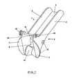
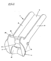
- a bowsprit or anchor davit in accordance with the invention includes an elongate, substantially U-shaped frame or main body made up from a first or rear section 1, which is adapted to be preferably releasably affixed (in any known manner) to the deck of a vessel, and a second or front section 2 which is adapted to extend over the edge of a structural member - as for example a deck or the like surface - of a vessel on which the overall bowsprit or davit is to be mounted.
- the U-shaped frame is made up from opposed side wall members 3 and 4 extending longitudinally of the bowsprit from front to rear thereof, and a substantially flat bottom or base 5,6 extending therebetween.
- the overall bowsprit is a unitary member, constructed from a material of a suitable strength, as for example steel or the like.
- the base 6 of the front section 2 preferably depends at an acute angle downwardly from the base 5 of the rear section 1.
- the overall bowsprit frame may be releasably attached to the deck or the like surface of the vessel in any suitable manner and using any suitable means, as for example one or more bolts and associated locknuts.
- the base or bottom 5 of the rear section 1 may be provided, at or in the vicinity of the rear section of the overall frame, with one or more pre-drilled or pre-formed apertures (not shown).
- the opposed side wall members 3 and 4 are, over the length of the rear section 1, of a lesser height than over the length of the front section 2.
- the rear section 1 of the bowsprit is of a greater length than the front section 2.
- each side wall member 3 and 4 adjacent the outermost extremity of the front section 2 of the frame there is provided a shaped flap 7 extending substantially normally thereto.
- These flaps 7 function to assist in feeding in of an anchor rope or chain to the bowsprit, to ensure an acceptable degree of directional control therefor. They also protect the anchor rope or chain from unwanted damage - as for example from chafing, scraping or even severing - since there is thus no sharp surface or knife edge to be engaged thereby. This is in marked contrast to known and currently in use arrangements, wherein the front edge of side members of a bowsprit constitute an effective knife edge or cutting surface.
- a first or primary guide roller 10 extending laterally of the front section 2 and preferably mounted for rotation between the side members 3 and 4 thereof.
- the centre-line or rotational axis of the primary roller 10 is disposed below the base of the rear section 1.
- This primary roller 10 is intended to receive and guide an anchor rope and/or chain, during the operation of raising or setting the anchor.
- a variety of different methods and means may be provided for mounting the roller 10 between the side members 3 and 4 of the front section 2.
- a bolt or the like means 11 (preferably of the standard hexagonal head type) may be disposed laterally of the front section 2, such to be located in opposed apertures 12 extending through the opposed sides 3 and 4.
- a locknut or the like means 13 can be employed to fix such bolt 11 in place transversely of the front section 2.
- a support bushing or spacer tube 14 may be disposed on the bolt 11, thereby to allow for rotation of the roller 10 as disposed thereon.
- the roller 10 will be of a substantial V-shape, having a groove formed centrally thereof.
- the outer surface of the roller 10 may have a plurality of grooves formed therein, whereby to enhance engagement of the anchor rope or chain thereby.
- the roller or pulley wheel 10 itself can be formed from any suitable material, preferably a high strength plastics material.
- a secondary roller 15 in the preferred embodiments illustrated in the form of a straight roller of a suitable high strength plastics material.
- this secondary roller 15 is mounted for rotation on a bolt or the like means 11, preferably with the interposition of a bushing or spacer tube 14, with the bolt 11 and associated bushing 14 and secondary roller 15 being releasably affixed transversely of the front section 2, by means of a locknut 13.
- each side wall member 3 and 4 of the front section 2 there is provided a means adapted to releasably extend therebetween, thereby to maintain those uppermost ends a fixed distance apart from one another, and also to allow for releasing of the anchor line or chain as and if desired.
- an elongate member 20 is provided, preferably threaded at one end 21 thereof and having means 22 at the other end thereof to facilitate handling/turning, such elongate member 20 being adapted, in use, to extend transversely of the front section 2 and to extend through complementary shaped apertures 23 provided in the sides thereof.
- a locknut or the like 24 may be employed to secure this elongate member 20 in place, against unwanted release through the effects of vibration.
- the means for handling 22 can be in the form of a shaped and knurled end section which, in use, is disposed externally of the front section 2.
- the elongate member 20 preferably has at least one protrusion thereon, hereinafter termed a roll or tie pin, extending substantially normally therefrom, such serving to prevent unwanted separation of the elongate member or support bolt 20 from the overall assembly.
- annular sleeve or the like may be provided on the internal surface of one side wall member of the bowsprit, at or in the vicinity of the uppermost edge thereof, said sleeve or the like being adapted to receive, and releasably retain, the threaded end of the elongate member 20.
- the secondary roller 15 is mounted or positioned so as to have its axis substantially in line with the base of the rear section 1. This is in contrast to known and previously in use arrangements, wherein a single roller was mounted at a location relatively above the base of the rear section, a configuration which has been formed to give rise to undue stresses on means employed for actually mounting the overall bowsprit to the deck. These stresses have been known to result in undesirable and unwanted bending of the overall bowsprit. With the present arrangement, in effect all forces are kept substantially parallel with the mounting screws or means, minimising any possible levering effect due to off-set loading.
- the first or primary roller 10 is disposed well forward of the junction of the respective front and rear sections 2 and 1. In the result the rope or chain is extremely unlikely to come into contact with any metal edge, further reducing the likelihood of damage thereto (as by chafing, scraping or even cutting).
- the hand-operated, releasable, solid screw-in bolt 20 extending across the upper ends of the side members 3 and 4 of the front section affords increased rigidity and strength to the bowsprit when installed.
- Such an arrangement is substantially proof against unwanted release or relaxation, as could occur with vibration in known arrangements. Furthermore, it ensures that the rope or chain cannot work free of the overall bowsprit during retrieval of an anchor, as can be possible with known arrangements.
- the arrangement is such that, when the anchor is not in use, the shank portion thereof is located within the U-shaped main body, with the fluke or leading end thereof located at or in the vicinity of the outermost free end of the second or front section 2.
- the anchor cable or line can then be tied off internally of the vessel in any suitable manner, whereby to retain the overall anchor in place relative to the bowsprit.
- the anchor cable/line is released and the anchor allowed to fall free from the bowsprit, to be deployed as necessary.
- it is time to retrieve the anchor then it is released from its footing and brought back into its storage location, within the bowsprit.
- the present arrangement by its very configuration, ,generally facilitates there procedures.
- a heavy duty (metal) sleeve or bushing 14 is employed.
- the bolt or the like 11 is tightened, the ends of this sleeve or bushing 14 come into contact with the internal surfaces of the side members 3, 4 of the bowsprit. The end result is an extremely rigid and significantly stronger unit.
- the overall bowsprit is stronger and less prone to unwanted bending or flexing under load, when compared with the prior art arrangement.
- the arrangement is such that the rope or chain cannot escape from the confines of the bowsprit during retrieval of an anchor, hence minimising the likelihood of injury to the unwary or careless user.
- the dimensions of the bowsprit of the present invention may be varied to suit the mounting conditions, the size of the anchors to be accommodated and other factors.
- the pulley wheel(s) could be mounted on a pair of pivoting arms to move in much the same direction, or could be mounted in a track; the entire assembly could be mounted at a different angle, for example, on a block of wood, instead of horizontal on the deck, and the anchor cable could take the form of a nylon rope or line, a wire rope, or an old-fashioned rope hawser, instead of a chain; suitable resilient elements or bumpers could also be employed in the structure.
- the assembly could be used to raise and lower, and to store, anchors of irregular configurations.
Landscapes
- Chemical & Material Sciences (AREA)
- Engineering & Computer Science (AREA)
- Combustion & Propulsion (AREA)
- Mechanical Engineering (AREA)
- Ocean & Marine Engineering (AREA)
- Emergency Lowering Means (AREA)
- Piles And Underground Anchors (AREA)
- Connection Of Plates (AREA)
Claims (18)
- Verbesserte Anordnung zum Anheben und Absenken eines Ankers, wobei die Anordnung ein lang gestrecktes Rahmenelement enthält, das umfasst: einen ersten oder hinteren im Wesentlichen U-förmigen Abschnitt (1), der dafür ausgelegt ist, im Gebrauch an der Oberfläche eines Decks oder dergleichen eines Schiffes montiert oder befestigt zu werden, wobei der erste Abschnitt (1) dafür ausgelegt ist, einen Hauptschaft des Ankers aufzunehmen und lösbar zu halten, wenn der Anker nicht verwendet wird oder in Gebrauch ist; und einen zweiten oder vorderen U-förmigen Abschnitt (2), der von dem ersten Abschnitt (1) longitudinal herabhängt und dafür ausgelegt ist, sich von dem Deck des Schiffes zu erstrecken, dadurch gekennzeichnet, dass der zweite Abschnitt (2) primäre (10) und sekundäre (15) Rollen oder Führungswalzen umfasst, um ein Seil oder ein Tau des Ankers zu führen, wenn er angehoben und abgesenkt wird, wobei die Rollen oder Führungswalzen (10, 15) sowohl longitudinal als auch in Höhenrichtung des zweiten Abschnitts (2) voneinander beabstandet sind;
der zweite Abschnitt (2) ferner Mittel (20) umfasst, die dafür ausgelegt sind, zwischen gegenüberliegenden Seiten des kanalförmigen zweiten Abschnitts (2) zu verlaufen, um den Abstand zwischen ihnen trotz Vibrationen und Belastungsbeanspruchungen, die während des Gebrauchs der Anordnung angetroffen werden, aufrecht zu erhalten; und
wobei die Anordnung eine einteilige Konstruktion ist. - Anordnung nach Anspruch 1, wobei der zweite Abschnitt (2) unter einem spitzen Winkel von dem ersten Abschnitt (1) nach unten hängt.
- Anordnung nach Anspruch 2, wobei jeder U-förmige Abschnitt (1, 2) aus gegenüberliegenden, beabstandeten länglichen Wandelementen (3, 4) gebildet ist, die ein zwischen ihnen angeordnetes Basiselement (5) besitzen, wobei das Basiselement (5) wenigstens längs eines Teils der Längsabmessung der Abschnitte (1, 2) verläuft.
- Anordnung nach Anspruch 3, wobei der erste Abschnitt (1) dafür ausgelegt ist, an der Oberfläche eines Decks oder dergleichen des Schiffes lösbar befestigt werden zu können.
- Anordnung nach Anspruch 4, wobei jedes der gegenüberliegenden Wandelemente (3, 4) des zweiten Abschnitts (2) an seinem freien Ende einen nach außen verlaufende Flansch oder eine nach außen verlaufende Klappe (7) aufweist, der bzw. die sich wenigstens längs eines Teils seiner Höhenabmessung erstreckt.
- Anordnung nach Anspruch 5, wobei die primäre Rolle oder Führungswalze (10) an dem äußersten freien Ende des zweiten Abschnitts (2) oder in dessen Nähe angeordnet ist, wobei sich die primäre Rolle oder Führungswalze (10) quer zu dem zweiten Abschnitt (2) erstreckt.
- Anordnung nach Anspruch 6, wobei die primäre Rolle (10) in dem zweiten Abschnitt (2) drehbar montiert ist, wobei die Drehachse hiervon unter der Ebene der Basis (5) des ersten Abschnitts (1) angeordnet ist.
- Anordnung nach Anspruch 7, wobei die sekundäre Rolle (15) für eine Drehung quer zu dem zweiten Abschnitt (2) angeordnet ist, wobei ihre Drehachse von der primäre Rolle (10) beabstandet ist und sich hinter dem zweiten Abschnitt (2) befindet und an einem Ort oberhalb der Ebene der Basis (5) des ersten Abschnitts (1) angeordnet ist.
- Anordnung nach Anspruch 8, wobei jede Rolle oder Führungswalze (10, 15) an einer Buchse (14) montiert ist, die ihrerseits an einem langgestreckten Element angeordnet ist, das quer zu dem zweiten Abschnitt (2) verläuft und daran lösbar befestigt ist.
- Anordnung nach Anspruch 9, wobei das langgestreckte Element ein Bolzen (11) ist, der an einem Ende einen Gewindeabschnitt besitzt, und das Befestigungsmittel eine Gegenmutter (13) ist, die außerhalb des Wandelements des zweiten Abschnitts (2) anzuordnen ist.
- Anordnung nach Anspruch 10, wobei die Rollen (10, 15) aus einem hochfesten Kunststoff hergestellt sind.
- Anordnung nach Anspruch 11, wobei wenigstens die primäre Rolle (10) eine im Wesentlichen konkave oder V-Form hat, deren Nut im Wesentlichen mittig angeordnet ist.
- Anordnung nach Anspruch 11, wobei wenigstens die primäre Rolle (10) mehrere Nuten, die in ihrer Oberfläche ausgebildet sind, besitzt.
- Anordnung nach Anspruch 13, die ein langgestrecktes Element (20) aufweist, das dafür ausgelegt ist, im Gebrauch zwischen den gegenüberliegenden Wandelementen (3, 4) des zweiten Abschnitts (2) an einem Ort in der Nähe ihres obersten Endes oder ihrer freien Oberfläche zu verlaufen, wobei das langgestreckte Element (20) dafür ausgelegt ist, durch eine Öffnung (23), die durch ein Wandelement (3 oder 4) vorgesehen ist, zu verlaufen und an dem anderen Wandelement (4 oder 3) lösbar befestigt zu sein.
- Anordnung nach Anspruch 14, wobei das langgestreckte Element (20) an einem Ende, das jenes Ende ist, das an dem anderen Wandelement (3 oder 4) lösbar befestigt werden soll, ein Gewinde aufweist.
- Anordnung nach Anspruch 15, wobei das andere Wandelement (4 oder 3) ein Gewindeelement aufweist, das dafür ausgelegt ist, sich nach innen zu erstrecken, um das Gewindeende des langgestreckten Elements (20) aufzunehmen und lösbar zu halten.
- Anordnung nach Anspruch 16, wobei das langgestreckte Element (20) wenigstens einen Stift oder einen ähnlichen Vorsprung, der sich im Wesentlichen senkrecht hiervon erstreckt, aufweist.
- Anordnung nach Anspruch 17, wobei das langgestreckte Element (20) an seinem anderen Ende ein Greifmittel in Form eines gerändelten Griffs (22), der sich im Wesentlichen senkrecht von dem anderen Ende erstreckt, aufweist.
Applications Claiming Priority (3)
| Application Number | Priority Date | Filing Date | Title |
|---|---|---|---|
| AUPS1983A AUPS198302A0 (en) | 2002-04-26 | 2002-04-26 | Improvements in bowsprits |
| AUPS198302 | 2002-04-26 | ||
| PCT/AU2003/000490 WO2003091091A1 (en) | 2002-04-26 | 2003-04-24 | Improvements in bowsprits |
Publications (3)
| Publication Number | Publication Date |
|---|---|
| EP1501722A1 EP1501722A1 (de) | 2005-02-02 |
| EP1501722A4 EP1501722A4 (de) | 2010-07-07 |
| EP1501722B1 true EP1501722B1 (de) | 2013-01-23 |
Family
ID=3835557
Family Applications (1)
| Application Number | Title | Priority Date | Filing Date |
|---|---|---|---|
| EP03714553A Expired - Lifetime EP1501722B1 (de) | 2002-04-26 | 2003-04-24 | Verbesserungen bei bugsprieten |
Country Status (8)
| Country | Link |
|---|---|
| US (2) | US7299759B2 (de) |
| EP (1) | EP1501722B1 (de) |
| JP (1) | JP4399273B2 (de) |
| CN (1) | CN100390017C (de) |
| AU (2) | AUPS198302A0 (de) |
| CA (1) | CA2482409C (de) |
| NZ (1) | NZ535997A (de) |
| WO (1) | WO2003091091A1 (de) |
Families Citing this family (12)
| Publication number | Priority date | Publication date | Assignee | Title |
|---|---|---|---|---|
| US8430048B2 (en) | 2011-02-11 | 2013-04-30 | Paul A. Tamulewicz | Line guard apparatus |
| KR200484425Y1 (ko) * | 2012-10-16 | 2017-09-05 | 대우조선해양 주식회사 | 리그용 체이서 행오프 |
| GB2532289A (en) * | 2014-11-17 | 2016-05-18 | Lewmar Ltd | Windlass assembly |
| CN107676373A (zh) * | 2017-10-19 | 2018-02-09 | 中船黄埔文冲船舶有限公司 | 一种角轮器 |
| USD862356S1 (en) * | 2018-01-09 | 2019-10-08 | Charles J Ceccarelli | Marine anchor nest |
| CN110329431B (zh) * | 2019-08-06 | 2020-06-23 | 杭州博途船用机电设备有限公司 | 运用于锚机的承载式滑轨锚支架结构及其控制方法 |
| CN111268032A (zh) * | 2020-04-17 | 2020-06-12 | 江龙船艇科技股份有限公司 | 一种船锚收放托架 |
| USD1065001S1 (en) | 2022-05-04 | 2025-03-04 | Grady-White Boats, Inc. | Boat anchor roller |
| US12420892B2 (en) | 2022-05-04 | 2025-09-23 | Grady-White Boats, Inc. | Boat anchor roller |
| CN116834897B (zh) * | 2023-08-02 | 2024-03-22 | 浙江欣海船舶设计研究院股份有限公司 | 一种用于甲板驳船的尾锚固定装置及使用方法 |
| KR102896728B1 (ko) * | 2023-12-07 | 2025-12-15 | 한국해양과학기술원 | 해양구조물용 탈부착 계류시스템 및 이를 이용한 해양구조물 계류방법 |
| KR20250098275A (ko) * | 2023-12-22 | 2025-07-01 | 한국해양과학기술원 | 해양구조물 계류용 체인 장력조절장치 |
Family Cites Families (16)
| Publication number | Priority date | Publication date | Assignee | Title |
|---|---|---|---|---|
| US2743696A (en) * | 1953-10-19 | 1956-05-01 | Maxwell George Earl | Anchor holder |
| US2742696A (en) | 1954-05-24 | 1956-04-24 | Holly L Williams | Twin lead cutting tool |
| US3577951A (en) * | 1969-03-19 | 1971-05-11 | Erwin M Smith | Apparatus for stowing and dropping an anchor |
| NL7015445A (de) * | 1969-11-07 | 1971-05-11 | ||
| AU472094B2 (en) * | 1972-10-11 | 1976-05-13 | roy JAMES DENNIS and KLEMENS KIELPIKOWSKI | Anchor boom |
| US4057025A (en) * | 1976-07-26 | 1977-11-08 | The Worth Company | Anchor davit |
| USD259240S (en) * | 1979-05-24 | 1981-05-19 | Myron Clayton E | Boat bow roller |
| US4248171A (en) * | 1979-07-02 | 1981-02-03 | Barbour Robert G | Anchor handling and securing assembly |
| USD259329S (en) * | 1979-11-26 | 1981-05-26 | Barbour Robert G | Boat anchor davit |
| SE436188B (sv) * | 1980-02-21 | 1984-11-19 | Bengt Thimander | Ankardevert |
| NL8004476A (nl) * | 1980-08-06 | 1982-03-01 | Haak Rob Van Den | Ankerrek. |
| FI71701C (fi) | 1980-09-25 | 1987-02-09 | Den Haak Rob Van | Ankare. |
| US4556007A (en) * | 1984-05-09 | 1985-12-03 | Deep Seven Co. | Anchor boom assembly |
| CA1278725C (en) * | 1985-09-27 | 1991-01-08 | Rob Van Den Haak | Anchor |
| AU734943B2 (en) | 1997-09-10 | 2001-06-28 | Rex William Francis | Improvements in anchors |
| US5996524A (en) * | 1998-08-20 | 1999-12-07 | Johnson; Robert K. | Boat anchor davit |
-
2002
- 2002-04-26 AU AUPS1983A patent/AUPS198302A0/en not_active Abandoned
-
2003
- 2003-04-24 WO PCT/AU2003/000490 patent/WO2003091091A1/en not_active Ceased
- 2003-04-24 JP JP2003587671A patent/JP4399273B2/ja not_active Expired - Fee Related
- 2003-04-24 US US10/512,323 patent/US7299759B2/en not_active Expired - Fee Related
- 2003-04-24 NZ NZ535997A patent/NZ535997A/en not_active IP Right Cessation
- 2003-04-24 CA CA2482409A patent/CA2482409C/en not_active Expired - Fee Related
- 2003-04-24 AU AU2003218912A patent/AU2003218912B2/en not_active Expired
- 2003-04-24 CN CNB038092468A patent/CN100390017C/zh not_active Expired - Fee Related
- 2003-04-24 EP EP03714553A patent/EP1501722B1/de not_active Expired - Lifetime
-
2007
- 2007-10-25 US US11/924,123 patent/US7484469B2/en not_active Expired - Fee Related
Also Published As
| Publication number | Publication date |
|---|---|
| US20080041289A1 (en) | 2008-02-21 |
| AUPS198302A0 (en) | 2002-06-06 |
| EP1501722A1 (de) | 2005-02-02 |
| NZ535997A (en) | 2009-11-27 |
| CA2482409C (en) | 2010-11-16 |
| AU2003218912A1 (en) | 2003-11-10 |
| CN1649767A (zh) | 2005-08-03 |
| CN100390017C (zh) | 2008-05-28 |
| CA2482409A1 (en) | 2003-11-06 |
| WO2003091091A1 (en) | 2003-11-06 |
| JP2005523838A (ja) | 2005-08-11 |
| US7299759B2 (en) | 2007-11-27 |
| JP4399273B2 (ja) | 2010-01-13 |
| US7484469B2 (en) | 2009-02-03 |
| US20050160961A1 (en) | 2005-07-28 |
| EP1501722A4 (de) | 2010-07-07 |
| AU2003218912B2 (en) | 2010-02-18 |
Similar Documents
| Publication | Publication Date | Title |
|---|---|---|
| US7484469B2 (en) | Bowsprits | |
| US6260498B1 (en) | Anchor cleat | |
| US5493983A (en) | Boat fender hanger | |
| EP0425497B1 (de) | Schiffsanker | |
| US5996524A (en) | Boat anchor davit | |
| US4248171A (en) | Anchor handling and securing assembly | |
| CA1278725C (en) | Anchor | |
| US3063402A (en) | Boat beaching and anchoring techniques and mechanisms | |
| US8567334B1 (en) | System for aiding line handling when docking a boat or other vessel | |
| US6626123B1 (en) | Bi-metal, light weight self penetrating boat anchor | |
| US4556007A (en) | Anchor boom assembly | |
| US4708086A (en) | Boat anchor | |
| US20050066870A1 (en) | Ground anchors using tines and compression plate | |
| IE44912B1 (en) | Improvements in anchor retrieval devices | |
| US4479452A (en) | Anchor handling and storage device | |
| US4480573A (en) | Rail mount anchor bracket | |
| US20060174811A1 (en) | Anchor rope lock | |
| NL1043284B9 (nl) | Ontwikkelingen en verbeteringen van "Automatische losinrichting bij het wegvaren" naar ook automatisch aanleggen | |
| US11648868B1 (en) | Vessel guidance system | |
| US6655310B1 (en) | Spring loaded bollard | |
| WO1994016936A1 (en) | An anchor device | |
| AU766289B2 (en) | Spring loaded bollard | |
| US20160200399A1 (en) | Snagless Push Pole Holder | |
| JPS6226191A (ja) | 引き船 | |
| WO2005123496A1 (en) | Device for automatically releasing anchors, particularly of the plow type |
Legal Events
| Date | Code | Title | Description |
|---|---|---|---|
| PUAI | Public reference made under article 153(3) epc to a published international application that has entered the european phase |
Free format text: ORIGINAL CODE: 0009012 |
|
| 17P | Request for examination filed |
Effective date: 20041126 |
|
| AK | Designated contracting states |
Kind code of ref document: A1 Designated state(s): AT BE BG CH CY CZ DE DK EE ES FI FR GB GR HU IE IT LI LU MC NL PT RO SE SI SK TR |
|
| AX | Request for extension of the european patent |
Extension state: AL LT LV MK |
|
| A4 | Supplementary search report drawn up and despatched |
Effective date: 20100604 |
|
| 17Q | First examination report despatched |
Effective date: 20100915 |
|
| REG | Reference to a national code |
Ref country code: DE Ref legal event code: R079 Ref document number: 60343171 Country of ref document: DE Free format text: PREVIOUS MAIN CLASS: B63B0021220000 Ipc: B63B0015000000 |
|
| GRAP | Despatch of communication of intention to grant a patent |
Free format text: ORIGINAL CODE: EPIDOSNIGR1 |
|
| RIC1 | Information provided on ipc code assigned before grant |
Ipc: B63B 21/22 20060101ALI20120606BHEP Ipc: B63B 15/00 20060101AFI20120606BHEP |
|
| GRAS | Grant fee paid |
Free format text: ORIGINAL CODE: EPIDOSNIGR3 |
|
| RAP1 | Party data changed (applicant data changed or rights of an application transferred) |
Owner name: FRANCIS, REX WILLIAM |
|
| RIN1 | Information on inventor provided before grant (corrected) |
Inventor name: FRANCIS, REX WILLIAM |
|
| GRAA | (expected) grant |
Free format text: ORIGINAL CODE: 0009210 |
|
| AK | Designated contracting states |
Kind code of ref document: B1 Designated state(s): AT BE BG CH CY CZ DE DK EE ES FI FR GB GR HU IE IT LI LU MC NL PT RO SE SI SK TR |
|
| REG | Reference to a national code |
Ref country code: GB Ref legal event code: FG4D |
|
| REG | Reference to a national code |
Ref country code: CH Ref legal event code: EP |
|
| REG | Reference to a national code |
Ref country code: CH Ref legal event code: EP Ref country code: AT Ref legal event code: REF Ref document number: 594794 Country of ref document: AT Kind code of ref document: T Effective date: 20130215 |
|
| REG | Reference to a national code |
Ref country code: IE Ref legal event code: FG4D |
|
| REG | Reference to a national code |
Ref country code: DE Ref legal event code: R096 Ref document number: 60343171 Country of ref document: DE Effective date: 20130321 |
|
| REG | Reference to a national code |
Ref country code: AT Ref legal event code: MK05 Ref document number: 594794 Country of ref document: AT Kind code of ref document: T Effective date: 20130123 |
|
| REG | Reference to a national code |
Ref country code: NL Ref legal event code: VDEP Effective date: 20130123 |
|
| PG25 | Lapsed in a contracting state [announced via postgrant information from national office to epo] |
Ref country code: ES Free format text: LAPSE BECAUSE OF FAILURE TO SUBMIT A TRANSLATION OF THE DESCRIPTION OR TO PAY THE FEE WITHIN THE PRESCRIBED TIME-LIMIT Effective date: 20130504 Ref country code: CY Free format text: LAPSE BECAUSE OF FAILURE TO SUBMIT A TRANSLATION OF THE DESCRIPTION OR TO PAY THE FEE WITHIN THE PRESCRIBED TIME-LIMIT Effective date: 20130123 Ref country code: BG Free format text: LAPSE BECAUSE OF FAILURE TO SUBMIT A TRANSLATION OF THE DESCRIPTION OR TO PAY THE FEE WITHIN THE PRESCRIBED TIME-LIMIT Effective date: 20130423 Ref country code: AT Free format text: LAPSE BECAUSE OF FAILURE TO SUBMIT A TRANSLATION OF THE DESCRIPTION OR TO PAY THE FEE WITHIN THE PRESCRIBED TIME-LIMIT Effective date: 20130123 Ref country code: BE Free format text: LAPSE BECAUSE OF FAILURE TO SUBMIT A TRANSLATION OF THE DESCRIPTION OR TO PAY THE FEE WITHIN THE PRESCRIBED TIME-LIMIT Effective date: 20130123 Ref country code: SE Free format text: LAPSE BECAUSE OF FAILURE TO SUBMIT A TRANSLATION OF THE DESCRIPTION OR TO PAY THE FEE WITHIN THE PRESCRIBED TIME-LIMIT Effective date: 20130123 |
|
| PG25 | Lapsed in a contracting state [announced via postgrant information from national office to epo] |
Ref country code: GR Free format text: LAPSE BECAUSE OF FAILURE TO SUBMIT A TRANSLATION OF THE DESCRIPTION OR TO PAY THE FEE WITHIN THE PRESCRIBED TIME-LIMIT Effective date: 20130424 Ref country code: NL Free format text: LAPSE BECAUSE OF FAILURE TO SUBMIT A TRANSLATION OF THE DESCRIPTION OR TO PAY THE FEE WITHIN THE PRESCRIBED TIME-LIMIT Effective date: 20130123 Ref country code: SI Free format text: LAPSE BECAUSE OF FAILURE TO SUBMIT A TRANSLATION OF THE DESCRIPTION OR TO PAY THE FEE WITHIN THE PRESCRIBED TIME-LIMIT Effective date: 20130123 Ref country code: FI Free format text: LAPSE BECAUSE OF FAILURE TO SUBMIT A TRANSLATION OF THE DESCRIPTION OR TO PAY THE FEE WITHIN THE PRESCRIBED TIME-LIMIT Effective date: 20130123 Ref country code: PT Free format text: LAPSE BECAUSE OF FAILURE TO SUBMIT A TRANSLATION OF THE DESCRIPTION OR TO PAY THE FEE WITHIN THE PRESCRIBED TIME-LIMIT Effective date: 20130523 |
|
| PG25 | Lapsed in a contracting state [announced via postgrant information from national office to epo] |
Ref country code: CZ Free format text: LAPSE BECAUSE OF FAILURE TO SUBMIT A TRANSLATION OF THE DESCRIPTION OR TO PAY THE FEE WITHIN THE PRESCRIBED TIME-LIMIT Effective date: 20130123 Ref country code: RO Free format text: LAPSE BECAUSE OF FAILURE TO SUBMIT A TRANSLATION OF THE DESCRIPTION OR TO PAY THE FEE WITHIN THE PRESCRIBED TIME-LIMIT Effective date: 20130123 Ref country code: EE Free format text: LAPSE BECAUSE OF FAILURE TO SUBMIT A TRANSLATION OF THE DESCRIPTION OR TO PAY THE FEE WITHIN THE PRESCRIBED TIME-LIMIT Effective date: 20130123 Ref country code: SK Free format text: LAPSE BECAUSE OF FAILURE TO SUBMIT A TRANSLATION OF THE DESCRIPTION OR TO PAY THE FEE WITHIN THE PRESCRIBED TIME-LIMIT Effective date: 20130123 Ref country code: DK Free format text: LAPSE BECAUSE OF FAILURE TO SUBMIT A TRANSLATION OF THE DESCRIPTION OR TO PAY THE FEE WITHIN THE PRESCRIBED TIME-LIMIT Effective date: 20130123 |
|
| PG25 | Lapsed in a contracting state [announced via postgrant information from national office to epo] |
Ref country code: MC Free format text: LAPSE BECAUSE OF FAILURE TO SUBMIT A TRANSLATION OF THE DESCRIPTION OR TO PAY THE FEE WITHIN THE PRESCRIBED TIME-LIMIT Effective date: 20130123 |
|
| PLBE | No opposition filed within time limit |
Free format text: ORIGINAL CODE: 0009261 |
|
| REG | Reference to a national code |
Ref country code: CH Ref legal event code: PL |
|
| STAA | Information on the status of an ep patent application or granted ep patent |
Free format text: STATUS: NO OPPOSITION FILED WITHIN TIME LIMIT |
|
| PG25 | Lapsed in a contracting state [announced via postgrant information from national office to epo] |
Ref country code: IT Free format text: LAPSE BECAUSE OF FAILURE TO SUBMIT A TRANSLATION OF THE DESCRIPTION OR TO PAY THE FEE WITHIN THE PRESCRIBED TIME-LIMIT Effective date: 20130123 |
|
| 26N | No opposition filed |
Effective date: 20131024 |
|
| REG | Reference to a national code |
Ref country code: IE Ref legal event code: MM4A |
|
| PG25 | Lapsed in a contracting state [announced via postgrant information from national office to epo] |
Ref country code: LI Free format text: LAPSE BECAUSE OF NON-PAYMENT OF DUE FEES Effective date: 20130430 Ref country code: CH Free format text: LAPSE BECAUSE OF NON-PAYMENT OF DUE FEES Effective date: 20130430 Ref country code: DE Free format text: LAPSE BECAUSE OF NON-PAYMENT OF DUE FEES Effective date: 20131101 |
|
| REG | Reference to a national code |
Ref country code: FR Ref legal event code: ST Effective date: 20131231 |
|
| REG | Reference to a national code |
Ref country code: DE Ref legal event code: R097 Ref document number: 60343171 Country of ref document: DE Effective date: 20131024 |
|
| REG | Reference to a national code |
Ref country code: DE Ref legal event code: R119 Ref document number: 60343171 Country of ref document: DE Effective date: 20131101 |
|
| PG25 | Lapsed in a contracting state [announced via postgrant information from national office to epo] |
Ref country code: FR Free format text: LAPSE BECAUSE OF NON-PAYMENT OF DUE FEES Effective date: 20130430 |
|
| PG25 | Lapsed in a contracting state [announced via postgrant information from national office to epo] |
Ref country code: IE Free format text: LAPSE BECAUSE OF NON-PAYMENT OF DUE FEES Effective date: 20130424 |
|
| PG25 | Lapsed in a contracting state [announced via postgrant information from national office to epo] |
Ref country code: TR Free format text: LAPSE BECAUSE OF FAILURE TO SUBMIT A TRANSLATION OF THE DESCRIPTION OR TO PAY THE FEE WITHIN THE PRESCRIBED TIME-LIMIT Effective date: 20130123 |
|
| PG25 | Lapsed in a contracting state [announced via postgrant information from national office to epo] |
Ref country code: LU Free format text: LAPSE BECAUSE OF NON-PAYMENT OF DUE FEES Effective date: 20130424 Ref country code: HU Free format text: LAPSE BECAUSE OF FAILURE TO SUBMIT A TRANSLATION OF THE DESCRIPTION OR TO PAY THE FEE WITHIN THE PRESCRIBED TIME-LIMIT; INVALID AB INITIO Effective date: 20030424 |
|
| PGFP | Annual fee paid to national office [announced via postgrant information from national office to epo] |
Ref country code: GB Payment date: 20190430 Year of fee payment: 17 |
|
| GBPC | Gb: european patent ceased through non-payment of renewal fee |
Effective date: 20200424 |
|
| PG25 | Lapsed in a contracting state [announced via postgrant information from national office to epo] |
Ref country code: GB Free format text: LAPSE BECAUSE OF NON-PAYMENT OF DUE FEES Effective date: 20200424 |