EP1501691B1 - Monitoring device and patch assembly - Google Patents
Monitoring device and patch assembly Download PDFInfo
- Publication number
- EP1501691B1 EP1501691B1 EP03724354A EP03724354A EP1501691B1 EP 1501691 B1 EP1501691 B1 EP 1501691B1 EP 03724354 A EP03724354 A EP 03724354A EP 03724354 A EP03724354 A EP 03724354A EP 1501691 B1 EP1501691 B1 EP 1501691B1
- Authority
- EP
- European Patent Office
- Prior art keywords
- monitoring device
- patch
- platform
- encapsulation material
- electronic monitoring
- Prior art date
- Legal status (The legal status is an assumption and is not a legal conclusion. Google has not performed a legal analysis and makes no representation as to the accuracy of the status listed.)
- Expired - Lifetime
Links
- 238000012806 monitoring device Methods 0.000 title claims description 106
- 239000000463 material Substances 0.000 claims description 85
- 238000005538 encapsulation Methods 0.000 claims description 71
- 238000012544 monitoring process Methods 0.000 claims description 44
- 238000000034 method Methods 0.000 claims description 23
- 239000000853 adhesive Substances 0.000 claims description 8
- 230000001070 adhesive effect Effects 0.000 claims description 8
- 238000004382 potting Methods 0.000 description 12
- 229920001971 elastomer Polymers 0.000 description 11
- 239000005060 rubber Substances 0.000 description 11
- 239000000203 mixture Substances 0.000 description 10
- -1 bromobutyl Chemical group 0.000 description 8
- 125000004432 carbon atom Chemical group C* 0.000 description 6
- 229920000647 polyepoxide Polymers 0.000 description 6
- 239000003822 epoxy resin Substances 0.000 description 5
- 239000004814 polyurethane Substances 0.000 description 5
- 229920002396 Polyurea Polymers 0.000 description 4
- 238000009472 formulation Methods 0.000 description 4
- LNEPOXFFQSENCJ-UHFFFAOYSA-N haloperidol Chemical compound C1CC(O)(C=2C=CC(Cl)=CC=2)CCN1CCCC(=O)C1=CC=C(F)C=C1 LNEPOXFFQSENCJ-UHFFFAOYSA-N 0.000 description 4
- 229920002635 polyurethane Polymers 0.000 description 4
- 244000043261 Hevea brasiliensis Species 0.000 description 3
- IISBACLAFKSPIT-UHFFFAOYSA-N bisphenol A Chemical compound C=1C=C(O)C=CC=1C(C)(C)C1=CC=C(O)C=C1 IISBACLAFKSPIT-UHFFFAOYSA-N 0.000 description 3
- 239000003795 chemical substances by application Substances 0.000 description 3
- 150000001875 compounds Chemical class 0.000 description 3
- 125000005442 diisocyanate group Chemical group 0.000 description 3
- VLKZOEOYAKHREP-UHFFFAOYSA-N n-Hexane Chemical compound CCCCCC VLKZOEOYAKHREP-UHFFFAOYSA-N 0.000 description 3
- 229920003052 natural elastomer Polymers 0.000 description 3
- 229920001194 natural rubber Polymers 0.000 description 3
- 230000029058 respiratory gaseous exchange Effects 0.000 description 3
- 239000002904 solvent Substances 0.000 description 3
- PLIKAWJENQZMHA-UHFFFAOYSA-N 4-aminophenol Chemical compound NC1=CC=C(O)C=C1 PLIKAWJENQZMHA-UHFFFAOYSA-N 0.000 description 2
- RTZKZFJDLAIYFH-UHFFFAOYSA-N Diethyl ether Chemical compound CCOCC RTZKZFJDLAIYFH-UHFFFAOYSA-N 0.000 description 2
- RPNUMPOLZDHAAY-UHFFFAOYSA-N Diethylenetriamine Chemical compound NCCNCCN RPNUMPOLZDHAAY-UHFFFAOYSA-N 0.000 description 2
- 229920002943 EPDM rubber Polymers 0.000 description 2
- BRLQWZUYTZBJKN-UHFFFAOYSA-N Epichlorohydrin Chemical compound ClCC1CO1 BRLQWZUYTZBJKN-UHFFFAOYSA-N 0.000 description 2
- 239000004593 Epoxy Substances 0.000 description 2
- JOYRKODLDBILNP-UHFFFAOYSA-N Ethyl urethane Chemical compound CCOC(N)=O JOYRKODLDBILNP-UHFFFAOYSA-N 0.000 description 2
- XSQUKJJJFZCRTK-UHFFFAOYSA-N Urea Chemical compound NC(N)=O XSQUKJJJFZCRTK-UHFFFAOYSA-N 0.000 description 2
- 125000003118 aryl group Chemical group 0.000 description 2
- 239000004202 carbamide Substances 0.000 description 2
- 239000003054 catalyst Substances 0.000 description 2
- 238000006243 chemical reaction Methods 0.000 description 2
- 239000013530 defoamer Substances 0.000 description 2
- 150000004985 diamines Chemical class 0.000 description 2
- QGBSISYHAICWAH-UHFFFAOYSA-N dicyandiamide Chemical compound NC(N)=NC#N QGBSISYHAICWAH-UHFFFAOYSA-N 0.000 description 2
- KORSJDCBLAPZEQ-UHFFFAOYSA-N dicyclohexylmethane-4,4'-diisocyanate Chemical compound C1CC(N=C=O)CCC1CC1CCC(N=C=O)CC1 KORSJDCBLAPZEQ-UHFFFAOYSA-N 0.000 description 2
- 125000002887 hydroxy group Chemical group [H]O* 0.000 description 2
- IQPQWNKOIGAROB-UHFFFAOYSA-N isocyanate group Chemical group [N-]=C=O IQPQWNKOIGAROB-UHFFFAOYSA-N 0.000 description 2
- 238000005259 measurement Methods 0.000 description 2
- 238000002844 melting Methods 0.000 description 2
- 230000008018 melting Effects 0.000 description 2
- 239000000178 monomer Substances 0.000 description 2
- ISWSIDIOOBJBQZ-UHFFFAOYSA-N phenol group Chemical group C1(=CC=CC=C1)O ISWSIDIOOBJBQZ-UHFFFAOYSA-N 0.000 description 2
- 229920000642 polymer Polymers 0.000 description 2
- 238000002360 preparation method Methods 0.000 description 2
- 230000000284 resting effect Effects 0.000 description 2
- FAGUFWYHJQFNRV-UHFFFAOYSA-N tetraethylenepentamine Chemical compound NCCNCCNCCNCCN FAGUFWYHJQFNRV-UHFFFAOYSA-N 0.000 description 2
- 229920002725 thermoplastic elastomer Polymers 0.000 description 2
- 229920002397 thermoplastic olefin Polymers 0.000 description 2
- 229920002803 thermoplastic polyurethane Polymers 0.000 description 2
- RUELTTOHQODFPA-UHFFFAOYSA-N toluene 2,6-diisocyanate Chemical compound CC1=C(N=C=O)C=CC=C1N=C=O RUELTTOHQODFPA-UHFFFAOYSA-N 0.000 description 2
- QMWAEOQXUXMSLU-UHFFFAOYSA-N 1,3,5-trichloro-1,3,5-triazinane-2,4,6-trione Chemical compound ClN1C(=O)N(Cl)C(=O)N(Cl)C1=O.ClN1C(=O)N(Cl)C(=O)N(Cl)C1=O QMWAEOQXUXMSLU-UHFFFAOYSA-N 0.000 description 1
- AZYRZNIYJDKRHO-UHFFFAOYSA-N 1,3-bis(2-isocyanatopropan-2-yl)benzene Chemical compound O=C=NC(C)(C)C1=CC=CC(C(C)(C)N=C=O)=C1 AZYRZNIYJDKRHO-UHFFFAOYSA-N 0.000 description 1
- VGHSXKTVMPXHNG-UHFFFAOYSA-N 1,3-diisocyanatobenzene Chemical compound O=C=NC1=CC=CC(N=C=O)=C1 VGHSXKTVMPXHNG-UHFFFAOYSA-N 0.000 description 1
- WZCQRUWWHSTZEM-UHFFFAOYSA-N 1,3-phenylenediamine Chemical compound NC1=CC=CC(N)=C1 WZCQRUWWHSTZEM-UHFFFAOYSA-N 0.000 description 1
- OHLKMGYGBHFODF-UHFFFAOYSA-N 1,4-bis(isocyanatomethyl)benzene Chemical compound O=C=NCC1=CC=C(CN=C=O)C=C1 OHLKMGYGBHFODF-UHFFFAOYSA-N 0.000 description 1
- ALQLPWJFHRMHIU-UHFFFAOYSA-N 1,4-diisocyanatobenzene Chemical compound O=C=NC1=CC=C(N=C=O)C=C1 ALQLPWJFHRMHIU-UHFFFAOYSA-N 0.000 description 1
- CBCKQZAAMUWICA-UHFFFAOYSA-N 1,4-phenylenediamine Chemical compound NC1=CC=C(N)C=C1 CBCKQZAAMUWICA-UHFFFAOYSA-N 0.000 description 1
- QGLRLXLDMZCFBP-UHFFFAOYSA-N 1,6-diisocyanato-2,4,4-trimethylhexane Chemical compound O=C=NCC(C)CC(C)(C)CCN=C=O QGLRLXLDMZCFBP-UHFFFAOYSA-N 0.000 description 1
- VILCJCGEZXAXTO-UHFFFAOYSA-N 2,2,2-tetramine Chemical compound NCCNCCNCCN VILCJCGEZXAXTO-UHFFFAOYSA-N 0.000 description 1
- YBRVSVVVWCFQMG-UHFFFAOYSA-N 4,4'-diaminodiphenylmethane Chemical compound C1=CC(N)=CC=C1CC1=CC=C(N)C=C1 YBRVSVVVWCFQMG-UHFFFAOYSA-N 0.000 description 1
- RYGMFSIKBFXOCR-UHFFFAOYSA-N Copper Chemical compound [Cu] RYGMFSIKBFXOCR-UHFFFAOYSA-N 0.000 description 1
- 239000005058 Isophorone diisocyanate Substances 0.000 description 1
- 239000002841 Lewis acid Substances 0.000 description 1
- 239000002879 Lewis base Substances 0.000 description 1
- 239000004721 Polyphenylene oxide Substances 0.000 description 1
- 125000001931 aliphatic group Chemical group 0.000 description 1
- 125000000217 alkyl group Chemical group 0.000 description 1
- 150000001414 amino alcohols Chemical class 0.000 description 1
- 125000003277 amino group Chemical group 0.000 description 1
- 150000004982 aromatic amines Chemical class 0.000 description 1
- 239000012298 atmosphere Substances 0.000 description 1
- 239000011324 bead Substances 0.000 description 1
- HIFVAOIJYDXIJG-UHFFFAOYSA-N benzylbenzene;isocyanic acid Chemical class N=C=O.N=C=O.C=1C=CC=CC=1CC1=CC=CC=C1 HIFVAOIJYDXIJG-UHFFFAOYSA-N 0.000 description 1
- 235000010290 biphenyl Nutrition 0.000 description 1
- 239000004305 biphenyl Substances 0.000 description 1
- 229920005557 bromobutyl Polymers 0.000 description 1
- 125000000484 butyl group Chemical group [H]C([*])([H])C([H])([H])C([H])([H])C([H])([H])[H] 0.000 description 1
- 229920005549 butyl rubber Polymers 0.000 description 1
- 229920005556 chlorobutyl Polymers 0.000 description 1
- 229910052802 copper Inorganic materials 0.000 description 1
- 239000010949 copper Substances 0.000 description 1
- 230000008878 coupling Effects 0.000 description 1
- 238000010168 coupling process Methods 0.000 description 1
- 238000005859 coupling reaction Methods 0.000 description 1
- QSAWQNUELGIYBC-UHFFFAOYSA-N cyclohexane-1,2-dicarboxylic acid Chemical class OC(=O)C1CCCCC1C(O)=O QSAWQNUELGIYBC-UHFFFAOYSA-N 0.000 description 1
- 150000001993 dienes Chemical class 0.000 description 1
- 150000002009 diols Chemical class 0.000 description 1
- 238000005516 engineering process Methods 0.000 description 1
- 125000003700 epoxy group Chemical group 0.000 description 1
- 239000012467 final product Substances 0.000 description 1
- 238000005187 foaming Methods 0.000 description 1
- 239000011521 glass Substances 0.000 description 1
- 238000010438 heat treatment Methods 0.000 description 1
- 239000012948 isocyanate Substances 0.000 description 1
- ZFSLODLOARCGLH-UHFFFAOYSA-N isocyanuric acid Chemical compound OC1=NC(O)=NC(O)=N1 ZFSLODLOARCGLH-UHFFFAOYSA-N 0.000 description 1
- NIMLQBUJDJZYEJ-UHFFFAOYSA-N isophorone diisocyanate Chemical compound CC1(C)CC(N=C=O)CC(C)(CN=C=O)C1 NIMLQBUJDJZYEJ-UHFFFAOYSA-N 0.000 description 1
- 150000007517 lewis acids Chemical class 0.000 description 1
- 150000007527 lewis bases Chemical class 0.000 description 1
- 238000012423 maintenance Methods 0.000 description 1
- 238000004519 manufacturing process Methods 0.000 description 1
- 239000002184 metal Substances 0.000 description 1
- 229910052751 metal Inorganic materials 0.000 description 1
- 229910052755 nonmetal Inorganic materials 0.000 description 1
- 125000001997 phenyl group Chemical group [H]C1=C([H])C([H])=C(*)C([H])=C1[H] 0.000 description 1
- ZUOUZKKEUPVFJK-UHFFFAOYSA-N phenylbenzene Natural products C1=CC=CC=C1C1=CC=CC=C1 ZUOUZKKEUPVFJK-UHFFFAOYSA-N 0.000 description 1
- 229920001084 poly(chloroprene) Polymers 0.000 description 1
- 229920000768 polyamine Polymers 0.000 description 1
- 229920000728 polyester Polymers 0.000 description 1
- 229920000570 polyether Polymers 0.000 description 1
- 229920005862 polyol Polymers 0.000 description 1
- 150000003077 polyols Chemical class 0.000 description 1
- 229920006295 polythiol Polymers 0.000 description 1
- 229920003226 polyurethane urea Polymers 0.000 description 1
- 238000003825 pressing Methods 0.000 description 1
- 150000003141 primary amines Chemical class 0.000 description 1
- 125000002924 primary amino group Chemical group [H]N([H])* 0.000 description 1
- 125000004805 propylene group Chemical group [H]C([H])([H])C([H])([*:1])C([H])([H])[*:2] 0.000 description 1
- 230000001681 protective effect Effects 0.000 description 1
- 239000000376 reactant Substances 0.000 description 1
- 238000007151 ring opening polymerisation reaction Methods 0.000 description 1
- 150000003335 secondary amines Chemical class 0.000 description 1
- 230000035939 shock Effects 0.000 description 1
- 238000005476 soldering Methods 0.000 description 1
- 239000007787 solid Substances 0.000 description 1
- 229920003048 styrene butadiene rubber Polymers 0.000 description 1
- 239000000758 substrate Substances 0.000 description 1
- 239000000725 suspension Substances 0.000 description 1
- 229920001187 thermosetting polymer Polymers 0.000 description 1
- 150000003673 urethanes Chemical class 0.000 description 1
Images



Classifications
-
- G—PHYSICS
- G01—MEASURING; TESTING
- G01M—TESTING STATIC OR DYNAMIC BALANCE OF MACHINES OR STRUCTURES; TESTING OF STRUCTURES OR APPARATUS, NOT OTHERWISE PROVIDED FOR
- G01M17/00—Testing of vehicles
- G01M17/007—Wheeled or endless-tracked vehicles
- G01M17/02—Tyres
-
- B—PERFORMING OPERATIONS; TRANSPORTING
- B60—VEHICLES IN GENERAL
- B60C—VEHICLE TYRES; TYRE INFLATION; TYRE CHANGING; CONNECTING VALVES TO INFLATABLE ELASTIC BODIES IN GENERAL; DEVICES OR ARRANGEMENTS RELATED TO TYRES
- B60C23/00—Devices for measuring, signalling, controlling, or distributing tyre pressure or temperature, specially adapted for mounting on vehicles; Arrangement of tyre inflating devices on vehicles, e.g. of pumps or of tanks; Tyre cooling arrangements
- B60C23/02—Signalling devices actuated by tyre pressure
- B60C23/04—Signalling devices actuated by tyre pressure mounted on the wheel or tyre
- B60C23/0491—Constructional details of means for attaching the control device
- B60C23/0493—Constructional details of means for attaching the control device for attachment on the tyre
-
- B—PERFORMING OPERATIONS; TRANSPORTING
- B60—VEHICLES IN GENERAL
- B60C—VEHICLE TYRES; TYRE INFLATION; TYRE CHANGING; CONNECTING VALVES TO INFLATABLE ELASTIC BODIES IN GENERAL; DEVICES OR ARRANGEMENTS RELATED TO TYRES
- B60C23/00—Devices for measuring, signalling, controlling, or distributing tyre pressure or temperature, specially adapted for mounting on vehicles; Arrangement of tyre inflating devices on vehicles, e.g. of pumps or of tanks; Tyre cooling arrangements
- B60C23/02—Signalling devices actuated by tyre pressure
- B60C23/04—Signalling devices actuated by tyre pressure mounted on the wheel or tyre
Definitions
- the present invention generally relates to a patch for mounting an electronic monitoring device to the inside surface of a pneumatic tire. More particularly, the present invention relates to a patch having an electronic monitoring device encapsulated directly to the patch to form an assembly that is mounted to a pneumatic tire. The invention also related to methods of forming the monitoring device and patch assembly.
- Protecting monitoring devices against harsh tire conditions has been accomplished in the past by encapsulating the monitoring device in an encapsulation or potting material.
- the potting material is poured over the monitoring device and fills the voids around the elements of the monitoring device.
- the material hardens and forms a protective block having a high modulus of elasticity around the elements of the monitoring device.
- the monitoring device is protected in this manner from the flexing and shock forces experienced in a pneumatic tire.
- Rubber patches are also known in the art to mount monitoring devices to the inner surface of a tire.
- the potted monitoring device has been connected to the patch with adhesive and the patch was then adhered to the innerliner of the tire.
- Other methods of mounting monitoring devices inside tires include forming a pocket in the tire and placing the monitoring device in the pocket.
- Other methods have placed a rubber patch over the top of the monitoring device to hold the monitoring device against the tire sidewall.
- the present invention provides a monitoring device and patch assembly that is ready for mounting to the inside of the tire.
- the invention solves the problems in the art by directly potting the monitoring device to an attachment patch to form an assembly that may be mounted to a tire.
- the invention provides a method of forming an electronic monitoring device and patch assembly that is adapted to be mounted to a pneumatic tire, the method comprising the steps of: (a) providing an attachment patch having a first side, a second side, and a platform extending from the first side; (b) providing at least a portion of an electronic monitoring device; and (c) encapsulating the at least one portion of the electronic monitoring device directly to the platform of the attachment patch to connect the at least one portion of the electronic monitoring device to the attachment patch; wherein the platform has an overhang; the method including the step of substantially surrounding the overhang with the encapsulation material.
- the invention provides a patch for mounting a monitoring device to the inside of a pneumatic tire comprising: a body having a first side, a second side, and a platform extending from the first side; at least a first portion of an electronic monitoring device; and an encapsulation material substantially surrounding the at least first portion of the electronic monitoring device and at least a portion of the platform to connect the at least first portion of the electronic monitoring device to the patch; wherein the platform includes an overhang; and the encapsulation material is directly applied and then cured to the platform so as to directly and securely bond with the material of the platform to connect the encapsulation material and the electronic monitoring device to the material of the platform.
- the invention further provides a patch for mounting a monitoring device to the inside of a pneumatic tire; comprising: a body having a first side, a second side, and a platform extending from the first side; the platform having an overhang; at least a first portion of an electronic monitoring device; an encapsulation material substantially surrounding the at least first portion of the electronic monitoring device; and the encapsulation material substantially surrounding the overhang of the platform to connect the at least first portion of the electronic monitoring device to the patch; wherein the encapsulation material is directly applied and then cured to the platform so as to directly and securely bond with the material of the platform to connect the encapsulation material and the electronic monitoring device to the material of the platform.
- the assembly includes a patch having a platform.
- An electronic monitoring device or a monitoring package is positioned adjacent the patch with an encapsulation material surrounding at least a portion of the electronic monitoring device/package and at least a portion of the platform.
- the encapsulation material connects the monitoring device/package to the patch.
- the invention also provides a patch and monitoring device assembly wherein the patch includes a platform having an overhang. At least a portion of the overhang and the monitoring device are encapsulated to connected the monitoring device to the patch.
- Another aspect of the invention provides placing the connecting elements used to electrically connect the monitoring package to an antenna embedded within the patch in a location where the connecting elements are surrounded by the encapsulation material.
- the method of the present invention includes the steps of providing a patch having a platform, positioning at least a portion of an electronic monitoring device adjacent the patch, and encapsulating at least a portion of the electronic monitoring device and at least a portion of the platform.
- Assembly 10 preferably mounts the electronic monitoring device to the innerliner 12 of a pneumatic tire 14 so that the electronic monitoring device may monitor at least one engineering condition of tire 14.
- Assembly 10 generally includes an attachment patch 20 and an encapsulated monitoring device 22.
- Attachment patch 20 is used to connect encapsulated monitoring device 22 to innerliner 12 so that the monitoring device may perform its measurements.
- Attachment patch 20 includes a first side 24 configured to receive encapsulated monitoring device 22 and a second side 26 configured to attach to tire 14.
- Attachment patch 20 is preferably fabricated from rubber.
- the rubber material is preferably vulcanized at a pre-selected temperature and a time sufficient to vulcanize the patch.
- the patch may be fabricated from a rubber selected from the group consisting of Ethylene Propylene Diene Monomer (EPDM) rubber, butyl rubber, natural rubber, neoprene, and mixtures thereof.
- EPDM Ethylene Propylene Diene Monomer
- patches made from these rubber compositions may be cured by heating to a temperature of about 150 degrees Celsius and holding this temperature for about thirty minutes. The time and temperature may be modified as necessary to achieve sufficient curing of the patch for further manufacturing steps.
- SBR Styrene-Butadiene rubber
- patches made from these rubber compositions may be cured by heating to a temperature of about 150 degrees Celsius and holding this temperature for about thirty minutes. The time and temperature may be modified as necessary to achieve sufficient curing of the patch for further manufacturing steps.
- patch 20 may be fabricated from a variety of other rubber mixtures known in the art. In addition to rubbers, patch 20 may be fabricated from other materials that may be adhered to tire 14 and accept encapsulated monitoring device 22 as described below.
- Thermoplastic Elastomers, Thermoplastic Urethanes or Thermoplastic Olefins may also be used to form attachment patch 20.
- Patch 20 carries an antenna 30 used to send and receive signals from encapsulating monitoring device 22.
- Antenna 30 includes connecting elements 32 that protrude outwardly from the outer perimeter of patch 20. Connecting elements 32 may be the male or female portion of a pin and socket-type connector. Connecting elements 32 are used to allow a monitoring package 34 to be plugged into antenna 30 after antenna 30 is cured into to patch 20. Antenna 30 may be connected to patch 20 in a variety of other ways other than being cured into patch 20. For instance, antenna 30 may be mounted on an outer surface of patch 20.
- Monitoring package 34 may include the various sensors, controllers, memory devices, and power supplies necessary to perform the monitoring, transmitting, and receiving functions desired in the art. Monitoring package 34 must be connected to antenna 30 so that it may communicate with a data gathering device position outside of tire 14. Monitoring package 34 also includes connecting elements 36 that are configured to mate with connecting elements 32 to form a direct electrical connection between monitoring package 34 and antenna 30.
- Monitoring package 34 is encapsulated with an encapsulation material 40 directly to attachment patch 20 such that encapsulation material 40 is chemically and/or physically bonded to attachment patch 20.
- a frame 42 is fabricated and attached to first side 24 of attachment patch 20 by an adhesive 44 by applying adhesive 44 around frame 42 and ensuring a continuous bead of adhesive 44 around the perimeter.
- a copper faced board having a thickness of 0.0345 inches is used to fabricate frame 42 by soldering the ends of four pieces together to form frame 42.
- Another preferred material for forming frame 42 is glass-filled epoxy.
- substantially any material may be used for frame 42 that will not interfere with a radio frequency signal if frame 42 remains connected to encapsulated monitoring device 22 as depicted in Fig. 5 and will not melt at the relatively high encapsulation or potting temperature. This temperature is typically 95-125 degrees Celsius.
- frame 42 is held against first side 24 of attachment patch 20 by applying pressure as indicated by the numeral 46 against frame 42.
- Pressure 46 maintains the correct position of frame 42 and prevents encapsulation material 40 from leaking out from between frame 42 and attachment patch 20.
- Frame 42 is positioned on attachment patch 20 such that connecting elements 32 are disposed within frame 42.
- the position of connecting elements 32 with respect to frame 42 is referred to as the connection location. It is an important aspect to provide strength around the connection location so that the connections between monitoring package 34 and antenna 30 do not become loose with extended use of patch 10.
- frame 42 may need to be sandblasted and degreased with solvent to clean the surface prior to performing the encapsulation steps.
- the copper-faced board discussed above is preferably sandblasted and solvent washed to clean the surface.
- first side 24 of attachment patch 20 is preferably cleaned and primed with a 3% 1, 3, 5 - T ri c hloro-s- t riazine t rione (Trichloroisocyanuric acid) (TCTT) solutions in butyl actetate. Side 24 was then wiped with a piece of Rymplecloth to remove the excess solvent and surface dirt. Patch 20 was then allowed to dry thoroughly.
- Adhesive 44 used around frame 42 is preferably FUSOR® 320 (five parts by weight)/310 B (two parts by weight). FUSOR® is available from Lord Corporation. Adhesive 44 is then cured in an oven at 80 degrees Celsius for thirty minutes.
- Monitoring package 34 is then positioned within frame 42 so that it is suspended within frame 42 adjacent first side 24.
- a chimney 48 may be attached to a sensor (such as a pressure sensor or a temperature sensor) on monitoring package 34 so that it may communicate with the atmosphere surrounding encapsulated monitoring device 22 after encapsulation material 40 is cured.
- Chimney 48 provides an air passage 50 to monitoring package 34.
- encapsulation material 40 is introduced inside frame 42 to substantially surround monitoring package 34 and to fill substantially all voids around monitoring package 34 as depicted in Fig. 5.
- encapsulation material 40 is a formulation including 100 gm STYCAST® 2651; 7 gm Catalyst 9; and 3 drops defoamer 88.
- encapsulation material 40 is a formulation including 110 gm STYCAST® 2651; 10 gm Phenyl Gycidyl Ether; 9.4gm Catalyst 9; and 6 drops of defoamer 88. These materials were mixed together at room temperature until thoroughly mixed.
- Frame 42 may be left in position as depicted in Fig. 5 or removed as depicted in Fig. 6.
- encapsulation materials 40 will also function. For instance, a variety of epoxies and urethanes that are pourable and cure to a rigid tough material having a high modulus of elasticity may be used. It is desired that encapsulation material 40 having a Young's modulus of at least 30,000 psi and which is capable of being molded around electronic monitoring package 34. Preferably, encapsulation material 40 will have a Young's modulus at least 100,000 psi.
- STYCAST®2651 is the preferred encapsulation material.
- high melting point polyurethanes and/or polyureas may be utilized.
- the polyurethanes are derived from polysiocyanates which generally have the formula R(NO) n where n is an integer of 2, 3 or 4 with approximately 2 being preferred.
- the "n” may, however, vary and often is not an integer because combinations of various polysiocyanates can be utilized.
- R is an aliphatic having from about 2 to about 20 carbon atoms or preferably an aromatic including an alkyl substituted aromatic having from about 6 to about 20 carbon atoms with from about 6 to about 15 carbon atoms being desired, or combinations thereof.
- polysiocyanates examples include 1,6-diisocyanto hexane; 2,2,4-and/or 2,4,4 trimethylhexamethylene diisocyanate; p- and m-tetramethyl xylene diisocyanate; dicyclohexylmethane-4,4'-diisocyanate (Hydrogenated MDI); 4,4-methylene diphenyl isocyanate (MDI); p- and m-phenylene diisocyanate; 2,4-and/or 2,6-toluene diisocyanate (TDI); durene-1,4-diisocyanate; isophorone diisocyanate and isopropylene bis-(p-phenyl isocyanate).
- TDI is desirably utilized.
- the various diphenylmethane diisocyanates (MDI) and mixtures of MDI with polymeric MDI having an average isocyanate functionality of from about 2 to about 3.2
- polyurethanes and/or polyureas are well known to the art and to the literature.
- a short chain oligomer or polymer derived from polyester or polyether polyols generally having a molecular weight of from about 55 to about 1,000 and preferably from about 6 to about 200 are reacted with the above-noted diisocyanates to form a urethane prepolymer.
- a short chain diamine can be utilized and reacted with the above-noted diisocyanates to form a urea prepolymer.
- Aromatic diisocyanates are generally utilized to yield high melting point urethane or urea prepolymers which also generally have a high modulus of elasticity.
- the resulting prepolymer is subsequently reacted with diols, diamine, diacids, or amino alcohols, and the like to cure the same and form a polyurethane or polyurea.
- the polyurethanes and/or polyureas are formed by reacting an existing prepolymer with the above-noted curing or chain extending agents.
- the equivalent ratio of isocyanate groups (NCO) reacted with the hydroxyl groups (OH) or amine groups (NH 2 ) of the short chain compound is generally from about 0.90 to about 1.10, desirably from about 0.95 to about 1.05, and preferably from about 0.98 to about 1.02.
- thermoset epoxy resins are preferred.
- the epoxy resin or polymer is generally formed by the reaction of bisphenol A and epichlorohydrin.
- the preparation of epoxy resins is well known to the literature and to the art.
- epichlorohydrin is reacted with a variety of hydroxy, carboxy, or amino compounds to form monomers with two or more epoxied groups, and these monomers are then used in the reaction with bisphenol A.
- Examples of such compounds are the diglycidyl derivative of cyclohexane-1,2-dicarboxylic acid, the triglycidyl derivates of p-aminophenol and cyanuric acid, and the polyglycidyl derivative of phenolic prepolymers.
- Epoxidized diolefins can also be employed.
- Various co-reactants can be utilized to cure epoxy resins either through the epoxied or hydroxyl groups.
- Polyamines such as primary or secondary amines are a common curing agent such as aliphatic amines having a total of from about 2 to about 18 carbon atoms and desirably from about 4 to about 8 carbon atoms.
- Suitable compounds include diethylene triamine, triethylenetetraamine, tetraethylene pentaamine, 4,4'-diaminodiphenylmethane, and polyaminoamides. A combination of diethylene triamine and tetraethylene pentaamine is often desired.
- Aromatic amines can also be utilized such as those having a total of from 6 to 20 carbon atoms such as meta or paraphenylene diamine and the like.
- Other curing agents including polythiols, dicyandiamide (cyanoguanidine), diisocyanates, and phenolic prepolymers. Curing of epoxy resins can also be achieved by ring opening polymerization of the epoxied groups using either Lewis acids or Lewis bases.
- a first embodiment of the present invention of an assembly used to mount an electronic monitoring device to the inside surface of a pneumatic tire is indicated generally by the numeral 110 in Fig. 11.
- Assembly 110 may be used to mount the electronic monitoring device to the innerliner 12 of a pneumatic tire 14 so that the electronic monitoring device may monitor at least one engineering condition of tire 14.
- the engineering condition may be the temperature of tire 14, the pressure of tire 14, or other conditions known in the art.
- Assembly 110 generally includes an attachment patch 120 and an encapsulated monitoring device 122 (Fig. 11).
- Attachment patch 120 is used to connect encapsulated monitoring device 122 to innerliner 12 so that the monitoring device may perform its measurements.
- Attachment patch 120 includes a body having a first side 124 configured to receive encapsulated monitoring device 122 and a second side 126 configured to be attached to tire 14.
- Attachment patch 120 is preferably fabricated from rubber as described above with respect to patch 20. In addition to rubbers, patch 120 may be fabricated from other materials that may be adhered to tire 14 and accept encapsulated monitoring device 122. Thermoplastic Elastomers, Thermoplastic Urethanes or Thermoplastic Olefins may also be used to form attachment patch 120.
- a platform 128 extends from first side 124 of attachment patch 120.
- Platform 128 includes a sidewall that extends generally vertically from first side 124 of patch 120.
- Platform 128 includes at least one overhang 129 that extends outwardly from the sidewall of platform 128.
- Overhang 129 includes a lower surface that opposes first side 124 such that a space is defined between overhang 129 and first side 124.
- overhang 129 may be a single continuous protrusion that extends about the circumference of platform 128.
- overhang 129 may include a plurality of spaced overhang portions disposed about the circumference of platform 128.
- overhang 129 may be a single protrusion that does not extend around the entire periphery of the platform 128.
- overhang 129 extends from the upper surface of platform 128.
- overhang 129 extends out from an intermediate portion of the sidewall of platform 128.
- platform 128 is solid.
- platform 128 may be hollow or define a plurality of openings. When hollow, patch 128 may receive portions of the encapsulation material.
- Overhang 129 may have a smoothly curved outer surface and is free of sharp edges.
- Platform 128 may also define a recessed collar 131 that is configured to receive a mold 133 that is used to form encapsulated monitoring device 122.
- Collar 131 is defined by a recess in the sidewall of platform 128.
- Mold 133 may include a first portion 135 and a second portion 137 that cooperate to form an encapsulation chamber 139 bounded by portions 135 and 137 as well as patch 120.
- first mold portion 135 engages collar 131 such that platform 128 projects up into chamber 139 with overhang 129 disposed entirely within chamber 139.
- first mold portion 135 abuts against platform 128 without the necessity of collar.
- assembly 110 is formed by first positioning mold portion 135 against patch 120 to locate platform 128 and overhang 129 in chamber 139. This configuration is depicted in Fig. 8.
- the user then positions the monitoring package 134 within chamber 139.
- Monitoring package 134 may include the elements described above with respect to monitoring package 34 and may, in some embodiments, include the antenna of the system.
- monitoring package 134 is suspended within chamber 139 by holders 141 that are attached to one of mold portions 135 and 137. The suspension of monitoring package 134 allows the encapsulation material 140 to substantially surround and protect monitoring package 134.
- Holders 141 may be thin wires that suspend monitoring package 134 within chamber 139. Holders 141 may be removed or left in place when the encapsulation material 140 is placed in chamber 139. Holders 141 may be fabricated from a metal or a nonmetal.
- encapsulation material 140 (as described above) is placed into chamber 139 to surround and protect monitoring package 134.
- a breathing tube may be created form a pressure sensor if such a tube is desired.
- Encapsulation material 140 also surrounds overhang 129 such that a mechanical interference fit is created between encapsulation material 140 and patch 120 in addition to any bonding that occurs between encapsulation material 140 and patch 120. Platform 128 and overhang 129 thus help form a secure connection between encapsulation material 140 and patch 120. This step is depicted in Fig. 10.
- Encapsulation material 140 may then be cured. If desired, mold 133 is then removed yielding assembly 110. In other embodiments of the invention, mold 133 is left in place and forms part of assembly 110.
- assembly 210 is formed without the use of holders 141.
- Assembly 210 includes many of the same elements described above with respect to assembly 110 and the same numbers are used to refer to these elements.
- monitoring package 134 is suspended within chamber 139 by filling a first portion of the chamber with a first portion 211 of encapsulation material 140 and resting monitoring package 134 on first portion 211 (Fig. 13).
- a second portion 212 of encapsulation material 140 is then placed over monitoring package 134 to substantially surround and protect monitoring package 134.
- a breathing tube may be formed for a pressure sensor if desired. Second portion 212 may be added while first portion 211 is curing so that the two portions bond together.
- assembly 310 is formed without the use of holders 141 and the antenna 330 of the monitoring device is spaced from monitoring package 134.
- Assembly 310 includes many of the same elements described above with respect to assembly 110 and the same numbers are used to refer to these elements.
- antenna 330 is suspended within chamber 139 by filling a first portion 311 of chamber 139 with encapsulation material 140. Antenna 330 is then placed on top of first portion 311. In other embodiments, antenna 330 may be suspended with a holder as described above with respect to holders 141.
- Antenna 330 includes a connecting element 331 that is used to electrically connect antenna 330 with monitoring package 134. Connecting element 331 may be a plug and socket connection, a soldered wire, an electrical coupling connection, or the like.
- Monitoring package 134 is suspended within chamber 139 by filling a second portion of the chamber with a second portion 312 of encapsulation material 140 and resting monitoring package 134 on second portion 312 (Figs. 17 and 18). In another embodiment, monitoring package 134 may be supported by appropriate holders. Monitoring package 134 is connected to connecting element 331 at this time. A third portion 313 of encapsulation material 140 is then placed over monitoring package 134 to substantially surround and protect monitoring package 134. A breathing tube may be formed for a pressure sensor if desired. Second portion 312 may be added while first portion 311 is curing so that the two portions bond together. Similarly, third portion 313 may be added while second portion 312 is curing so that the two portions bond together.
- assembly 410 includes an antenna 430 connected to patch 120.
- antenna 430 is mounted to patch 120 and may be embedded within patch 120.
- a connecting element 431 is connected to antenna 430 and extends up through platform 128 into chamber 139.
- Monitoring package 134 is connected to connecting element 131 and may be suspended within chamber 139 by connecting element 131 as depicted in Fig. 22.
- Encapsulation material 140 is then placed into chamber 139 to surround monitoring package 134. In other embodiments, monitoring package 134 may be suspended within chamber 139 by any of the methods described above.
- the cured encapsulation material cooperates with overhang 129 on platform 128 to form an interference fit preventing the encapsulated monitoring package 134 from being separated from patch 102.
Landscapes
- Engineering & Computer Science (AREA)
- Mechanical Engineering (AREA)
- Physics & Mathematics (AREA)
- General Physics & Mathematics (AREA)
- Measuring Fluid Pressure (AREA)
- Arrangements For Transmission Of Measured Signals (AREA)
Description
- The present invention generally relates to a patch for mounting an electronic monitoring device to the inside surface of a pneumatic tire. More particularly, the present invention relates to a patch having an electronic monitoring device encapsulated directly to the patch to form an assembly that is mounted to a pneumatic tire. The invention also related to methods of forming the monitoring device and patch assembly.
- Monitoring the internal conditions of a pneumatic tire while the tire is in use on a vehicle is becoming increasingly desired in the art. One problem with this technology is protecting the relatively sensitive electronic monitoring device in the relatively harsh environment inside a tire. Another problem in the art is that the inner surface of a tire does not have surfaces where monitoring devices may be easily mounted in a secure manner.
- Protecting monitoring devices against harsh tire conditions has been accomplished in the past by encapsulating the monitoring device in an encapsulation or potting material. The potting material is poured over the monitoring device and fills the voids around the elements of the monitoring device. The material hardens and forms a protective block having a high modulus of elasticity around the elements of the monitoring device. The monitoring device is protected in this manner from the flexing and shock forces experienced in a pneumatic tire.
- Rubber patches are also known in the art to mount monitoring devices to the inner surface of a tire. The potted monitoring device has been connected to the patch with adhesive and the patch was then adhered to the innerliner of the tire. Other methods of mounting monitoring devices inside tires include forming a pocket in the tire and placing the monitoring device in the pocket. Other methods have placed a rubber patch over the top of the monitoring device to hold the monitoring device against the tire sidewall.
- One problem with these mounting solutions is the relatively high number of steps required to mount the monitoring device to the tire. Another problem is the number of times the monitoring device must be handled prior to mounting inside the tire. More importantly, the users of the monitoring devices desire stronger connections between the monitoring device and the tire.
- Another problem in the art occurs when the antenna is mounted in a different substrate than the monitoring device. In these situations, a connection must be formed between the monitoring device and the antenna. An example of this situation is shown in Patent Application Serial No. 09/301,781 filed April 29, 1999, which is owned by the Assignee of the present application. In this situation, a pair of connectors are used to form the direct physical connection between the antenna and the monitoring device. The problem that has occurred is that the adhesive used to bond the monitoring device to the patch is forced around the connectors sometimes flowing into the connectors. The art desires a solution to this problem by providing a method of connecting the encapsulated monitoring device to a patch while not fouling the connectors.
- International patent application WO 02/07993 and WO 01/74609 describe electronic tire maintenance systems for measuring a parameter of a device at a first location. The system includes a sensor for measuring the device parameter and generating a data signal representing the measured parameter. This document also describes a method of forming an electronic monitoring device and patch assembly.
- The present invention provides a monitoring device and patch assembly that is ready for mounting to the inside of the tire. The invention solves the problems in the art by directly potting the monitoring device to an attachment patch to form an assembly that may be mounted to a tire.
- In particular, the invention provides a method of forming an electronic monitoring device and patch assembly that is adapted to be mounted to a pneumatic tire, the method comprising the steps of: (a) providing an attachment patch having a first side, a second side, and a platform extending from the first side; (b) providing at least a portion of an electronic monitoring device; and (c) encapsulating the at least one portion of the electronic monitoring device directly to the platform of the attachment patch to connect the at least one portion of the electronic monitoring device to the attachment patch;
wherein the platform has an overhang; the method including the step of substantially surrounding the overhang with the encapsulation material. - Moreover, the invention provides a patch for mounting a monitoring device to the inside of a pneumatic tire comprising: a body having a first side, a second side, and a platform extending from the first side; at least a first portion of an electronic monitoring device; and an encapsulation material substantially surrounding the at least first portion of the electronic monitoring device and at least a portion of the platform to connect the at least first portion of the electronic monitoring device to the patch; wherein the platform includes an overhang; and the encapsulation material is directly applied and then cured to the platform so as to directly and securely bond with the material of the platform to connect the encapsulation material and the electronic monitoring device to the material of the platform.
- The invention further provides a patch for mounting a monitoring device to the inside of a pneumatic tire; comprising: a body having a first side, a second side, and a platform extending from the first side; the platform having an overhang; at least a first portion of an electronic monitoring device; an encapsulation material substantially surrounding the at least first portion of the electronic monitoring device; and the encapsulation material substantially surrounding the overhang of the platform to connect the at least first portion of the electronic monitoring device to the patch; wherein the encapsulation material is directly applied and then cured to the platform so as to directly and securely bond with the material of the platform to connect the encapsulation material and the electronic monitoring device to the material of the platform.
- In one embodiment of the invention, the assembly includes a patch having a platform. An electronic monitoring device or a monitoring package is positioned adjacent the patch with an encapsulation material surrounding at least a portion of the electronic monitoring device/package and at least a portion of the platform. The encapsulation material connects the monitoring device/package to the patch.
- The invention also provides a patch and monitoring device assembly wherein the patch includes a platform having an overhang. At least a portion of the overhang and the monitoring device are encapsulated to connected the monitoring device to the patch.
- Another aspect of the invention provides placing the connecting elements used to electrically connect the monitoring package to an antenna embedded within the patch in a location where the connecting elements are surrounded by the encapsulation material.
- The method of the present invention includes the steps of providing a patch having a platform, positioning at least a portion of an electronic monitoring device adjacent the patch, and encapsulating at least a portion of the electronic monitoring device and at least a portion of the platform.
-
- Fig. 1 is a sectional view of a pneumatic tire with an encapsulated monitoring device mounted to the innerliner of the tire with an attachment patch;
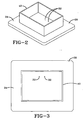
- Fig. 2 is a perspective view of the attachment patch with a potting frame assembled and placed on the upper surface of the attachment patch to surround the connectors for the antenna;
- Fig. 3 is a top plan view of Fig. 2;
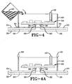
- Fig. 4 is a sectional side view of the attachment patch and the potting frame with the electronic monitoring device positioned within the potting frame and the potting material being poured into the potting frame;
- Fig. 4A is a view similar to Fig. 4 showing an alternative where the potting frame is held against the attachment patch with pressure;
- Fig. 5 is a view similar to Fig. 4 showing the potting frame substantially filled with the potting material; and
- Fig. 6 is a view similar to Fig. 4 showing one embodiment of the final product.
- Fig. 7 is a side view of the attachment patch used in a first embodiment of the invention.
- Fig. 8 is a section view showing a first portion of the mold connected to the attachment patch.
- Fig. 9 is a section view showing a second portion of the mold being connected to the first portion of the mold with the electronic monitoring device being suspended by the second portion of the mold.
- Fig. 10 is a section view showing the encapsulation material disposed in the mold around the electronic monitoring device.
- Fig. 11 is a section view of the assembly with the mold removed.
- Fig. 12 is a section view showing an initial step in forming a second embodiment of the assembly of the invention.
- Fig. 13 is a section view showing the electronic monitoring device and a portion of the encapsulation material being installed.
- Fig. 14 is a section view showing the remaining portion of the encapsulation material placed in the mold.
- Fig. 15 is a section view of the second embodiment of the assembly of the invention.
- Fig. 16 is a section view showing an initial step in forming a third embodiment of the assembly of the invention.
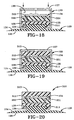
- Fig. 17 is a section view showing an antenna installed and a second layer of encapsulation material disposed over the antenna.
- Fig. 18 is a section view showing the monitoring device and second portion of the mold being installed.
- Fig. 19 is a section view showing the final layer of encapsulation material installed.
- Fig. 20 is a section view of the third embodiment of the invention.
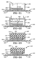
- Fig. 21 is a section view showing an initial step in forming a fourth embodiment of the assembly of the invention.
- Fig. 22 is a section view showing a monitoring device suspended within the mold.
- Fig. 23 is a section view showing the encapsulation material installed in the mold.
- Fig. 24 is a section view showing the fourth embodiment of the invention.
- Similar numbers refer to similar parts throughout the specification.
- An assembly used to mount an electronic monitoring device to the inside surface of a pneumatic tire is indicated generally by the numeral 10 in the drawings.
Assembly 10 preferably mounts the electronic monitoring device to theinnerliner 12 of apneumatic tire 14 so that the electronic monitoring device may monitor at least one engineering condition oftire 14. -
Assembly 10 generally includes anattachment patch 20 and an encapsulatedmonitoring device 22.Attachment patch 20 is used to connect encapsulatedmonitoring device 22 to innerliner 12 so that the monitoring device may perform its measurements.Attachment patch 20 includes afirst side 24 configured to receive encapsulatedmonitoring device 22 and asecond side 26 configured to attach to tire 14.Attachment patch 20 is preferably fabricated from rubber. The rubber material is preferably vulcanized at a pre-selected temperature and a time sufficient to vulcanize the patch. The patch may be fabricated from a rubber selected from the group consisting of Ethylene Propylene Diene Monomer (EPDM) rubber, butyl rubber, natural rubber, neoprene, and mixtures thereof. One preferred embodiment is a mixture of chlorobutyl rubber and natural rubber. Another preferred embodiment is bromobutyl rubber. Another embodiment is a mixture of Styrene-Butadiene rubber (SBR) natural rubber. Typically, patches made from these rubber compositions may be cured by heating to a temperature of about 150 degrees Celsius and holding this temperature for about thirty minutes. The time and temperature may be modified as necessary to achieve sufficient curing of the patch for further manufacturing steps. The present invention also contemplates thatpatch 20 may be fabricated from a variety of other rubber mixtures known in the art. In addition to rubbers,patch 20 may be fabricated from other materials that may be adhered to tire 14 and accept encapsulatedmonitoring device 22 as described below. Thermoplastic Elastomers, Thermoplastic Urethanes or Thermoplastic Olefins may also be used to formattachment patch 20. -
Patch 20 carries anantenna 30 used to send and receive signals from encapsulatingmonitoring device 22.Antenna 30 includes connectingelements 32 that protrude outwardly from the outer perimeter ofpatch 20.Connecting elements 32 may be the male or female portion of a pin and socket-type connector.Connecting elements 32 are used to allow amonitoring package 34 to be plugged intoantenna 30 afterantenna 30 is cured into to patch 20.Antenna 30 may be connected to patch 20 in a variety of other ways other than being cured intopatch 20. For instance,antenna 30 may be mounted on an outer surface ofpatch 20. Monitoringpackage 34 may include the various sensors, controllers, memory devices, and power supplies necessary to perform the monitoring, transmitting, and receiving functions desired in the art. Monitoringpackage 34 must be connected toantenna 30 so that it may communicate with a data gathering device position outside oftire 14. Monitoringpackage 34 also includes connectingelements 36 that are configured to mate with connectingelements 32 to form a direct electrical connection betweenmonitoring package 34 andantenna 30. - Monitoring
package 34 is encapsulated with anencapsulation material 40 directly toattachment patch 20 such thatencapsulation material 40 is chemically and/or physically bonded toattachment patch 20. In one embodiment, aframe 42 is fabricated and attached tofirst side 24 ofattachment patch 20 by an adhesive 44 by applyingadhesive 44 aroundframe 42 and ensuring a continuous bead of adhesive 44 around the perimeter. In one embodiment, a copper faced board having a thickness of 0.0345 inches is used to fabricateframe 42 by soldering the ends of four pieces together to formframe 42. Another preferred material for formingframe 42 is glass-filled epoxy. In other embodiments, substantially any material may be used forframe 42 that will not interfere with a radio frequency signal ifframe 42 remains connected to encapsulatedmonitoring device 22 as depicted in Fig. 5 and will not melt at the relatively high encapsulation or potting temperature. This temperature is typically 95-125 degrees Celsius. - In another embodiment,
frame 42 is held againstfirst side 24 ofattachment patch 20 by applying pressure as indicated by the numeral 46 againstframe 42.Pressure 46 maintains the correct position offrame 42 and preventsencapsulation material 40 from leaking out from betweenframe 42 andattachment patch 20. -
Frame 42 is positioned onattachment patch 20 such that connectingelements 32 are disposed withinframe 42. The position of connectingelements 32 with respect to frame 42 is referred to as the connection location. It is an important aspect to provide strength around the connection location so that the connections betweenmonitoring package 34 andantenna 30 do not become loose with extended use ofpatch 10. - Depending on the material used to fabricate
frame 42,frame 42 may need to be sandblasted and degreased with solvent to clean the surface prior to performing the encapsulation steps. For instance, the copper-faced board discussed above is preferably sandblasted and solvent washed to clean the surface. In addition,first side 24 ofattachment patch 20 is preferably cleaned and primed with a 3% 1, 3, 5 - Trichloro-s-triazinetrione (Trichloroisocyanuric acid) (TCTT) solutions in butyl actetate.Side 24 was then wiped with a piece of Rymplecloth to remove the excess solvent and surface dirt.Patch 20 was then allowed to dry thoroughly.Adhesive 44 used aroundframe 42 is preferably FUSOR® 320 (five parts by weight)/310 B (two parts by weight). FUSOR® is available from Lord Corporation.Adhesive 44 is then cured in an oven at 80 degrees Celsius for thirty minutes. - Monitoring
package 34 is then positioned withinframe 42 so that it is suspended withinframe 42 adjacentfirst side 24. Achimney 48 may be attached to a sensor (such as a pressure sensor or a temperature sensor) onmonitoring package 34 so that it may communicate with the atmosphere surrounding encapsulatedmonitoring device 22 afterencapsulation material 40 is cured.Chimney 48 provides anair passage 50 tomonitoring package 34. - After monitoring
package 34 is positioned adjacentfirst side 24 and withinframe 42,encapsulation material 40 is introduced insideframe 42 to substantially surroundmonitoring package 34 and to fill substantially all voids aroundmonitoring package 34 as depicted in Fig. 5. In the preferred embodiment,encapsulation material 40 is a formulation including 100 gm STYCAST® 2651; 7 gm Catalyst 9; and 3 drops defoamer 88. In another embodiment of the invention,encapsulation material 40 is a formulation including 110 gm STYCAST® 2651; 10 gm Phenyl Gycidyl Ether; 9.4gm Catalyst 9; and 6 drops of defoamer 88. These materials were mixed together at room temperature until thoroughly mixed. The formulation was degassed until foaming subsided. The formulation was then poured intoframe 42 and allowed to cure in an oven at 55 degrees Celsius for thirty minutes. It was then post-cured at 80 degrees Celsius for thirty minutes. This process results in a strong encapsulatedmonitoring device 22 directly bonded toattachment patch 20.Frame 42 may be left in position as depicted in Fig. 5 or removed as depicted in Fig. 6. - Various
other encapsulation materials 40 will also function. For instance, a variety of epoxies and urethanes that are pourable and cure to a rigid tough material having a high modulus of elasticity may be used. It is desired thatencapsulation material 40 having a Young's modulus of at least 30,000 psi and which is capable of being molded aroundelectronic monitoring package 34. Preferably,encapsulation material 40 will have a Young's modulus at least 100,000 psi. - STYCAST®2651 is the preferred encapsulation material. Alternatively, high melting point polyurethanes and/or polyureas may be utilized. The polyurethanes are derived from polysiocyanates which generally have the formula R(NO)n where n is an integer of 2, 3 or 4 with approximately 2 being preferred. The "n" may, however, vary and often is not an integer because combinations of various polysiocyanates can be utilized. R is an aliphatic having from about 2 to about 20 carbon atoms or preferably an aromatic including an alkyl substituted aromatic having from about 6 to about 20 carbon atoms with from about 6 to about 15 carbon atoms being desired, or combinations thereof. Examples of suitable polysiocyanates include 1,6-diisocyanto hexane; 2,2,4-and/or 2,4,4 trimethylhexamethylene diisocyanate; p- and m-tetramethyl xylene diisocyanate; dicyclohexylmethane-4,4'-diisocyanate (Hydrogenated MDI); 4,4-methylene diphenyl isocyanate (MDI); p- and m-phenylene diisocyanate; 2,4-and/or 2,6-toluene diisocyanate (TDI); durene-1,4-diisocyanate; isophorone diisocyanate and isopropylene bis-(p-phenyl isocyanate). TDI is desirably utilized. The various diphenylmethane diisocyanates (MDI) and mixtures of MDI with polymeric MDI having an average isocyanate functionality of from about 2 to about 3.2 are preferred.
- The preparation of the polyurethanes and/or polyureas are well known to the art and to the literature. For example, a short chain oligomer or polymer derived from polyester or polyether polyols generally having a molecular weight of from about 55 to about 1,000 and preferably from about 6 to about 200 are reacted with the above-noted diisocyanates to form a urethane prepolymer. Similarly, a short chain diamine can be utilized and reacted with the above-noted diisocyanates to form a urea prepolymer. Aromatic diisocyanates are generally utilized to yield high melting point urethane or urea prepolymers which also generally have a high modulus of elasticity. The resulting prepolymer is subsequently reacted with diols, diamine, diacids, or amino alcohols, and the like to cure the same and form a polyurethane or polyurea. Alternatively, the polyurethanes and/or polyureas are formed by reacting an existing prepolymer with the above-noted curing or chain extending agents.
- The equivalent ratio of isocyanate groups (NCO) reacted with the hydroxyl groups (OH) or amine groups (NH2) of the short chain compound is generally from about 0.90 to about 1.10, desirably from about 0.95 to about 1.05, and preferably from about 0.98 to about 1.02.
- In general, thermoset epoxy resins are preferred. The epoxy resin or polymer is generally formed by the reaction of bisphenol A and epichlorohydrin. The preparation of epoxy resins is well known to the literature and to the art. Generally, epichlorohydrin is reacted with a variety of hydroxy, carboxy, or amino compounds to form monomers with two or more epoxied groups, and these monomers are then used in the reaction with bisphenol A. Examples of such compounds are the diglycidyl derivative of cyclohexane-1,2-dicarboxylic acid, the triglycidyl derivates of p-aminophenol and cyanuric acid, and the polyglycidyl derivative of phenolic prepolymers. Epoxidized diolefins can also be employed. Various co-reactants can be utilized to cure epoxy resins either through the epoxied or hydroxyl groups. Polyamines such as primary or secondary amines are a common curing agent such as aliphatic amines having a total of from about 2 to about 18 carbon atoms and desirably from about 4 to about 8 carbon atoms. Suitable compounds include diethylene triamine, triethylenetetraamine, tetraethylene pentaamine, 4,4'-diaminodiphenylmethane, and polyaminoamides. A combination of diethylene triamine and tetraethylene pentaamine is often desired. Aromatic amines can also be utilized such as those having a total of from 6 to 20 carbon atoms such as meta or paraphenylene diamine and the like. Other curing agents including polythiols, dicyandiamide (cyanoguanidine), diisocyanates, and phenolic prepolymers. Curing of epoxy resins can also be achieved by ring opening polymerization of the epoxied groups using either Lewis acids or Lewis bases.
- A first embodiment of the present invention of an assembly used to mount an electronic monitoring device to the inside surface of a pneumatic tire is indicated generally by the numeral 110 in Fig. 11.
Assembly 110 may be used to mount the electronic monitoring device to theinnerliner 12 of apneumatic tire 14 so that the electronic monitoring device may monitor at least one engineering condition oftire 14. The engineering condition may be the temperature oftire 14, the pressure oftire 14, or other conditions known in the art. -
Assembly 110 generally includes anattachment patch 120 and an encapsulated monitoring device 122 (Fig. 11).Attachment patch 120 is used to connect encapsulatedmonitoring device 122 to innerliner 12 so that the monitoring device may perform its measurements. -
Attachment patch 120 includes a body having afirst side 124 configured to receive encapsulatedmonitoring device 122 and asecond side 126 configured to be attached totire 14.Attachment patch 120 is preferably fabricated from rubber as described above with respect to patch 20. In addition to rubbers,patch 120 may be fabricated from other materials that may be adhered to tire 14 and accept encapsulatedmonitoring device 122. Thermoplastic Elastomers, Thermoplastic Urethanes or Thermoplastic Olefins may also be used to formattachment patch 120. - A
platform 128 extends fromfirst side 124 ofattachment patch 120.Platform 128 includes a sidewall that extends generally vertically fromfirst side 124 ofpatch 120.Platform 128 includes at least oneoverhang 129 that extends outwardly from the sidewall ofplatform 128.Overhang 129 includes a lower surface that opposesfirst side 124 such that a space is defined betweenoverhang 129 andfirst side 124. In one embodiment of the invention,overhang 129 may be a single continuous protrusion that extends about the circumference ofplatform 128. In another embodiment of the invention,overhang 129 may include a plurality of spaced overhang portions disposed about the circumference ofplatform 128. In a further embodiment,overhang 129 may be a single protrusion that does not extend around the entire periphery of theplatform 128. In the embodiment of the invention depicted in the drawings,overhang 129 extends from the upper surface ofplatform 128. In other embodiments,overhang 129 extends out from an intermediate portion of the sidewall ofplatform 128. In the embodiment of the invention depicted in the drawings,platform 128 is solid. In other embodiments,platform 128 may be hollow or define a plurality of openings. When hollow,patch 128 may receive portions of the encapsulation material.Overhang 129 may have a smoothly curved outer surface and is free of sharp edges. -
Platform 128 may also define a recessedcollar 131 that is configured to receive amold 133 that is used to form encapsulatedmonitoring device 122.Collar 131 is defined by a recess in the sidewall ofplatform 128.Mold 133 may include afirst portion 135 and asecond portion 137 that cooperate to form anencapsulation chamber 139 bounded byportions patch 120. In the exemplary embodiment of the invention,first mold portion 135 engagescollar 131 such thatplatform 128 projects up intochamber 139 withoverhang 129 disposed entirely withinchamber 139. In other embodiments of the invention,first mold portion 135 abuts againstplatform 128 without the necessity of collar. - In the first embodiment of the invention,
assembly 110 is formed by firstpositioning mold portion 135 againstpatch 120 to locateplatform 128 andoverhang 129 inchamber 139. This configuration is depicted in Fig. 8. The user then positions themonitoring package 134 withinchamber 139.Monitoring package 134 may include the elements described above with respect tomonitoring package 34 and may, in some embodiments, include the antenna of the system. In the exemplary embodiment,monitoring package 134 is suspended withinchamber 139 byholders 141 that are attached to one ofmold portions monitoring package 134 allows theencapsulation material 140 to substantially surround and protectmonitoring package 134.Holders 141 may be thin wires that suspendmonitoring package 134 withinchamber 139.Holders 141 may be removed or left in place when theencapsulation material 140 is placed inchamber 139.Holders 141 may be fabricated from a metal or a nonmetal. - Once
monitoring package 134 is in place, encapsulation material 140 (as described above) is placed intochamber 139 to surround and protectmonitoring package 134. A breathing tube may be created form a pressure sensor if such a tube is desired.Encapsulation material 140 also surroundsoverhang 129 such that a mechanical interference fit is created betweenencapsulation material 140 andpatch 120 in addition to any bonding that occurs betweenencapsulation material 140 andpatch 120.Platform 128 andoverhang 129 thus help form a secure connection betweenencapsulation material 140 andpatch 120. This step is depicted in Fig. 10.Encapsulation material 140 may then be cured. If desired,mold 133 is then removed yieldingassembly 110. In other embodiments of the invention,mold 133 is left in place and forms part ofassembly 110. - In the second embodiment of the invention depicted in Figs. 12-15,
assembly 210 is formed without the use ofholders 141.Assembly 210 includes many of the same elements described above with respect toassembly 110 and the same numbers are used to refer to these elements. In the second alternative embodiment,monitoring package 134 is suspended withinchamber 139 by filling a first portion of the chamber with afirst portion 211 ofencapsulation material 140 and restingmonitoring package 134 on first portion 211 (Fig. 13). Asecond portion 212 ofencapsulation material 140 is then placed overmonitoring package 134 to substantially surround and protectmonitoring package 134. A breathing tube may be formed for a pressure sensor if desired.Second portion 212 may be added whilefirst portion 211 is curing so that the two portions bond together. - In the third embodiment of the invention depicted in Figs. 16-20,
assembly 310 is formed without the use ofholders 141 and theantenna 330 of the monitoring device is spaced frommonitoring package 134.Assembly 310 includes many of the same elements described above with respect toassembly 110 and the same numbers are used to refer to these elements. In the third embodiment,antenna 330 is suspended withinchamber 139 by filling afirst portion 311 ofchamber 139 withencapsulation material 140.Antenna 330 is then placed on top offirst portion 311. In other embodiments,antenna 330 may be suspended with a holder as described above with respect toholders 141.Antenna 330 includes a connectingelement 331 that is used to electrically connectantenna 330 withmonitoring package 134. Connectingelement 331 may be a plug and socket connection, a soldered wire, an electrical coupling connection, or the like. -
Monitoring package 134 is suspended withinchamber 139 by filling a second portion of the chamber with asecond portion 312 ofencapsulation material 140 and restingmonitoring package 134 on second portion 312 (Figs. 17 and 18). In another embodiment,monitoring package 134 may be supported by appropriate holders.Monitoring package 134 is connected to connectingelement 331 at this time. Athird portion 313 ofencapsulation material 140 is then placed overmonitoring package 134 to substantially surround and protectmonitoring package 134. A breathing tube may be formed for a pressure sensor if desired.Second portion 312 may be added whilefirst portion 311 is curing so that the two portions bond together. Similarly,third portion 313 may be added whilesecond portion 312 is curing so that the two portions bond together. - The fourth embodiment of the invention is depicted in Figs. 21-24 with the fourth embodiment of the assembly being indicated generally by the numeral 410. In the fourth embodiment,
assembly 410 includes anantenna 430 connected to patch 120. In the exemplary embodiment,antenna 430 is mounted to patch 120 and may be embedded withinpatch 120. A connectingelement 431 is connected toantenna 430 and extends up throughplatform 128 intochamber 139.Monitoring package 134 is connected to connectingelement 131 and may be suspended withinchamber 139 by connectingelement 131 as depicted in Fig. 22.Encapsulation material 140 is then placed intochamber 139 to surroundmonitoring package 134. In other embodiments,monitoring package 134 may be suspended withinchamber 139 by any of the methods described above. - In each of these embodiments, the cured encapsulation material cooperates with
overhang 129 onplatform 128 to form an interference fit preventing the encapsulatedmonitoring package 134 from being separated from patch 102.
Claims (18)
- A method of forming an electronic monitoring device and patch assembly that is adapted to be mounted to a pneumatic tire, the method comprising the steps of:(a) providing an attachment patch (120) having a first side (124), a second side (126), and a platform (128) extending from the first side (124); and(b) providing at least a portion of an electronic monitoring device (134); characterized in that the method further comprises the step of:(c) encapsulating the at least one portion of the electronic monitoring device (134) directly to the platform (128) of the attachment patch (120) to connect the at least one portion of the electronic monitoring device to the attachment patch;wherein the platform has an overhang (129); the method including the step of substantially surrounding the overhang (129) with the encapsulation material (140).
- The method of claim 1 further comprising the steps of:mounting an antenna (330) to the attachment patch (120);connecting the at least one portion of the electronic monitoring device to the antenna (330) at a connection location; andcovering the connection location during step (c).
- The method of claim 1, further comprising the steps of providing a mold (133); surrounding the monitoring device (134) with the mold; and filling the mold with encapsulation material (140).
- The method of claim 3, further comprising the step of engaging the platform (128) with the mold (133).
- The method of claim 4, further comprising the step of suspending the at least one portion of the monitoring device from the mold (133).
- The method of claim 1, wherein step (c) includes the steps of:providing a first portion (211) of encapsulation material;contacting the at least one portion of the monitoring device with the first portion of the encapsulation material; andproviding a second portion (212) of encapsulation material to substantially surround the at least one portion of the monitoring device.
- The method of claim 1, further comprising the steps of providing a second portion of the monitoring device (134).
- The method of claim 7, wherein step (c) includes the steps of:providing a first portion (311) of encapsulation material;contacting the second portion of the monitoring device (330) with the first portion (311) of the encapsulation material;providing a second portion (312) of encapsulation material to substantially surround the second portion (330) of the monitoring device (134);contacting the at least one portion (134) of the monitoring device with the second portion of the encapsulation material; andproviding a third portion (313) of encapsulation material to substantially surround the at least one portion of the monitoring device (134).
- The method of claim 1, further comprising the step of mounting the attachment patch to the inner surface of a pneumatic tire (14).
- A patch for mounting a monitoring device to the inside of a pneumatic tire (14) comprising:a body having a first side (124), a second side (126), and a platform (128) extending from the first side; wherein the platform (128) includes an overhang (129); andat least a first portion of an electronic monitoring device (134);characterized in that the patch further comprises:an encapsulation material (140) substantially surrounding the at least first portion of the electronic monitoring device and at least a portion of the platform (128) to connect the at least first portion of the electronic monitoring (134) device to the patch; andthe encapsulation material (140) is directly applied and then cured to the platform (128) so as to directly and securely bond with the material of the platform to connect the encapsulation material (140) and the electronic monitoring device to the material of the platform (128).
- The patch of claim 10, wherein the attachment patch is free of adhesive holding the encapsulation material (140) to the platform (128).
- The patch of claim 10, further comprising an antenna (330) mounted to the body; the antenna being electrically connected to the at least first portion of the electronic monitoring device (134).
- The patch of claim 10, further comprising an antenna (330) spaced from the at least first portion of the electronic monitoring device; the encapsulation material substantially surrounding the antenna.
- The patch of claim.10 wherein the encapsulation material is disposed intermediate the overhang (129) and the body.
- The patch of claim 10, wherein the platform defines a recessed collar (131).
- The patch of claim 15, further comprising an encapsulation mold (135); the encapsulation mold engaging the recessed collar (131).
- The patch of claim 16, wherein the platform includes an overhang (129); the overhang being substantially surrounded by the encapsulation mold (135).
- A patch (120) for mounting a monitoring device to the inside of a pneumatic tire; comprising:a body having a first side (124), a second side (126), and a platform (128) extending from the first side;the platform (128) having an overhang (129); andat least a first portion of an electronic monitoring device (134);characterized in that the patch further comprises:an encapsulation material (140) substantially surrounding the at least first portion of the electronic monitoring device (134); andthe encapsulation material (140) substantially surrounding the overhang (129) of the platform to connect the at least first portion of the electronic monitoring device to the patch (120);wherein the encapsulation (140) material is directly applied and then cured to the platform so as to directly and securely bond with the material of the platform to connect the encapsulation material and the electronic monitoring device to the material of the platform (128).
Applications Claiming Priority (3)
| Application Number | Priority Date | Filing Date | Title |
|---|---|---|---|
| US140607 | 2002-05-07 | ||
| US10/140,607 US7331367B2 (en) | 2000-03-31 | 2002-05-07 | Monitoring device and patch assembly |
| PCT/US2003/013512 WO2003095243A1 (en) | 2002-05-07 | 2003-04-29 | Monitoring device and patch assembly |
Publications (2)
| Publication Number | Publication Date |
|---|---|
| EP1501691A1 EP1501691A1 (en) | 2005-02-02 |
| EP1501691B1 true EP1501691B1 (en) | 2006-11-15 |
Family
ID=29418389
Family Applications (1)
| Application Number | Title | Priority Date | Filing Date |
|---|---|---|---|
| EP03724354A Expired - Lifetime EP1501691B1 (en) | 2002-05-07 | 2003-04-29 | Monitoring device and patch assembly |
Country Status (8)
| Country | Link |
|---|---|
| US (1) | US7331367B2 (en) |
| EP (1) | EP1501691B1 (en) |
| JP (1) | JP4216802B2 (en) |
| KR (2) | KR20050034641A (en) |
| AU (1) | AU2003231219A1 (en) |
| CA (1) | CA2484779C (en) |
| DE (1) | DE60309692T2 (en) |
| WO (1) | WO2003095243A1 (en) |
Cited By (4)
| Publication number | Priority date | Publication date | Assignee | Title |
|---|---|---|---|---|
| US8640535B2 (en) | 2009-09-30 | 2014-02-04 | Compagnie Generale Des Etablissements Michelin | Apparatus and method for tire temperature measurement |
| DE102007001279B4 (en) * | 2007-01-08 | 2021-02-11 | Continental Reifen Deutschland Gmbh | Pneumatic vehicle tires with an electronic module |
| EP3835044A1 (en) | 2019-12-10 | 2021-06-16 | Continental Reifen Deutschland GmbH | Method and joining system for fixing a receptacle to a tyre |
| US12128716B2 (en) | 2017-12-18 | 2024-10-29 | Pirelli Tyre S.P.A. | Tyre monitoring device comprising an electronic unit and tyre comprising said device |
Families Citing this family (36)
| Publication number | Priority date | Publication date | Assignee | Title |
|---|---|---|---|---|
| US6868717B2 (en) * | 1998-10-16 | 2005-03-22 | Bridgestone/Firestone North America Tire, Llc | Method and device to encapsulate tire tag |
| US6688353B1 (en) | 2000-03-31 | 2004-02-10 | Bridgestone/Firestone North American Tire, Llc | Attachment patch for mounting an electronic monitoring device to the inside of a pneumatic tire |
| US7331367B2 (en) | 2000-03-31 | 2008-02-19 | Bridgestone Firestone North American Tire, Llc | Monitoring device and patch assembly |
| DE10255138A1 (en) * | 2002-11-26 | 2004-06-17 | Iq-Mobil Electronics Gmbh | Holding device for fastening an electronic component |
| ATE328747T1 (en) | 2003-01-23 | 2006-06-15 | Michelin Soc Tech | FASTENING A RIGID ELEMENT TO A TIRE |
| BR8300869U (en) * | 2003-06-18 | 2003-11-25 | Techinvest Ltda | Device introduced in hidden receiver-emitter path of tires and the like |
| US7186308B2 (en) * | 2003-10-09 | 2007-03-06 | Michelin Recherche Et Technique S.A. | System and method for providing tire electronics mounting patches |
| US20050076982A1 (en) * | 2003-10-09 | 2005-04-14 | Metcalf Arthur Richard | Post patch assembly for mounting devices in a tire interior |
| US20060237109A1 (en) * | 2003-11-17 | 2006-10-26 | Anton Mangold | Holding device for fixing an electronic component |
| US20050126668A1 (en) * | 2003-12-16 | 2005-06-16 | Pierre Fornerod | Post patch for mounting devices inside tires |
| FR2867721A1 (en) * | 2004-03-18 | 2005-09-23 | Michelin Soc Tech | POCKET HOLDING ELECTRONIC SENSOR |
| US20050262934A1 (en) * | 2004-05-25 | 2005-12-01 | Sensfab Pte Ltd | Tyre pressure monitoring sensor |
| JP2005348032A (en) * | 2004-06-02 | 2005-12-15 | Yokohama Rubber Co Ltd:The | On-vehicle communication antenna |
| US7353720B2 (en) * | 2004-07-09 | 2008-04-08 | Michelin Recherche Et Technique, S.A. | Bridge patch for electromechanical transducer elements in tire assemblies |
| CN101052538A (en) * | 2004-11-12 | 2007-10-10 | 米其林技术公司 | Tread fixture patch for fixture rigid structure of tyres |
| JP4732788B2 (en) * | 2005-04-26 | 2011-07-27 | 株式会社ブリヂストン | Protective member, electronic monitoring device and pneumatic tire |
| CN101194296B (en) * | 2005-06-10 | 2011-07-27 | 米其林研究和技术股份有限公司 | Inductive Coupling of Piezoelectric Pulses |
| EP1889025B1 (en) * | 2005-06-10 | 2012-02-15 | Michelin Recherche et Technique S.A. | Use of piezoelectric sensor attached to electronics package housing |
| WO2007000781A1 (en) * | 2005-06-28 | 2007-01-04 | Pirelli Tyre S.P.A. | A tyre provided with a device for detecting at least one functional parameter of the tyre itself, and a method for detecting at least one functional parameter in a tyre |
| KR100736773B1 (en) * | 2006-10-25 | 2007-07-09 | 한국타이어 주식회사 | RDF tag mounting structure inside the tire |
| EP2205652A1 (en) * | 2007-10-30 | 2010-07-14 | Société de Technologie MICHELIN | Polyurethaneurea system |
| US20090151828A1 (en) * | 2007-12-15 | 2009-06-18 | Junling Zhao | Tire with antenna encapsulated with rubber compound containing thermoplastic |
| JP2009298328A (en) * | 2008-06-13 | 2009-12-24 | Bridgestone Corp | Pneumatic tire |
| US8742265B2 (en) * | 2008-08-29 | 2014-06-03 | Compagnie Generale Des Etablissements Michelin | 1-D tire patch apparatus and methodology |
| DE102009050268A1 (en) * | 2009-10-21 | 2011-05-05 | Rema Tip Top Gmbh | Mounting system for attaching brackets to elastomer components |
| JP4623229B1 (en) * | 2009-11-16 | 2011-02-02 | 横浜ゴム株式会社 | Transmitter for transmitting information on tire condition and tire condition monitoring system |
| FR2952856B1 (en) * | 2009-11-20 | 2012-01-06 | Continental Automotive France | ELECTRONIC UNIT ADAPTED TO BE POSITIONED ON THE INTERNAL SIDE OF A TIRE TREAD OF A PNEUMATIC |
| JP4623231B1 (en) * | 2009-11-30 | 2011-02-02 | 横浜ゴム株式会社 | Transmitter for transmitting information on tire condition and tire condition monitoring system |
| US9121885B2 (en) * | 2010-08-16 | 2015-09-01 | Infineon Technologies Ag | Sensor package and method of manufacturing thereof |
| US9016118B2 (en) | 2010-12-22 | 2015-04-28 | Caterpillar Inc. | Mounting structure |
| JP5943505B2 (en) * | 2011-10-31 | 2016-07-05 | 住友化学株式会社 | High voltage coil |
| JP2017071341A (en) * | 2015-10-08 | 2017-04-13 | 株式会社デンソー | Tire mount sensor and sensor device used therefor |
| JP6534634B2 (en) * | 2016-05-13 | 2019-06-26 | 太平洋工業株式会社 | Tire condition detection device |
| US10836222B2 (en) * | 2018-10-26 | 2020-11-17 | Sensata Technologies, Inc. | Tire mounted sensors with controlled orientation and removal detection |
| IT201900001575A1 (en) | 2019-02-04 | 2020-08-04 | Bridgestone Europe Nv Sa | TIRE FITTED WITH A TRANSPONDER |
| JP2023035683A (en) * | 2021-09-01 | 2023-03-13 | 株式会社ブリヂストン | Tire sensor and tire |
Family Cites Families (13)
| Publication number | Priority date | Publication date | Assignee | Title |
|---|---|---|---|---|
| US6239737B1 (en) | 1994-07-15 | 2001-05-29 | Micron Technology, Inc. | Method and apparatus for attaching a radio frequency transponder to an object |
| AU740137B2 (en) | 1998-02-12 | 2001-11-01 | Michelin Recherche Et Technique S.A. | Attachment means for a tire electronic package |
| US6217683B1 (en) | 1998-02-12 | 2001-04-17 | Michelin Recherche Et Technique S.A. | Monitored vehicle tire and monitor retainer assembly |
| US6534711B1 (en) * | 1998-04-14 | 2003-03-18 | The Goodyear Tire & Rubber Company | Encapsulation package and method of packaging an electronic circuit module |
| BR9912848A (en) * | 1998-08-03 | 2001-05-08 | Goodyear Tire & Rubber | Assembly of transponders in tires |
| US6474380B1 (en) | 1999-04-29 | 2002-11-05 | Bridgestone/Firestone North American Tire, Llc | Pneumatic tire and monitoring device including dipole antenna |
| US6192746B1 (en) | 1999-04-29 | 2001-02-27 | Bridgestone/Firestone Research, Inc. | Apparatus and method of providing electrical power to an active electronic device embedded within a tire |
| US6591671B2 (en) | 1999-08-16 | 2003-07-15 | The Goodyear Tire & Rubber Company | Monitoring pneumatic tire conditions |
| US6255940B1 (en) | 1999-10-01 | 2001-07-03 | The Goodyear Tire & Rubber Company | Apparatus for monitoring a condition of a tire |
| US7331367B2 (en) | 2000-03-31 | 2008-02-19 | Bridgestone Firestone North American Tire, Llc | Monitoring device and patch assembly |
| US6688353B1 (en) | 2000-03-31 | 2004-02-10 | Bridgestone/Firestone North American Tire, Llc | Attachment patch for mounting an electronic monitoring device to the inside of a pneumatic tire |
| US7161476B2 (en) * | 2000-07-26 | 2007-01-09 | Bridgestone Firestone North American Tire, Llc | Electronic tire management system |
| ES2381940T3 (en) | 2000-07-26 | 2012-06-01 | Bridgestone Americas Tire Operations, Llc | Electronic tire management system |
-
2002
- 2002-05-07 US US10/140,607 patent/US7331367B2/en not_active Expired - Lifetime
-
2003
- 2003-04-29 KR KR1020047017971A patent/KR20050034641A/en not_active Withdrawn
- 2003-04-29 EP EP03724354A patent/EP1501691B1/en not_active Expired - Lifetime
- 2003-04-29 WO PCT/US2003/013512 patent/WO2003095243A1/en not_active Ceased
- 2003-04-29 DE DE60309692T patent/DE60309692T2/en not_active Expired - Lifetime
- 2003-04-29 KR KR1020047017990A patent/KR101012607B1/en not_active Expired - Fee Related
- 2003-04-29 AU AU2003231219A patent/AU2003231219A1/en not_active Abandoned
- 2003-04-29 JP JP2004503295A patent/JP4216802B2/en not_active Expired - Lifetime
- 2003-04-29 CA CA2484779A patent/CA2484779C/en not_active Expired - Lifetime
Cited By (4)
| Publication number | Priority date | Publication date | Assignee | Title |
|---|---|---|---|---|
| DE102007001279B4 (en) * | 2007-01-08 | 2021-02-11 | Continental Reifen Deutschland Gmbh | Pneumatic vehicle tires with an electronic module |
| US8640535B2 (en) | 2009-09-30 | 2014-02-04 | Compagnie Generale Des Etablissements Michelin | Apparatus and method for tire temperature measurement |
| US12128716B2 (en) | 2017-12-18 | 2024-10-29 | Pirelli Tyre S.P.A. | Tyre monitoring device comprising an electronic unit and tyre comprising said device |
| EP3835044A1 (en) | 2019-12-10 | 2021-06-16 | Continental Reifen Deutschland GmbH | Method and joining system for fixing a receptacle to a tyre |
Also Published As
| Publication number | Publication date |
|---|---|
| JP4216802B2 (en) | 2009-01-28 |
| EP1501691A1 (en) | 2005-02-02 |
| WO2003095243A1 (en) | 2003-11-20 |
| AU2003231219A1 (en) | 2003-11-11 |
| DE60309692D1 (en) | 2006-12-28 |
| KR101012607B1 (en) | 2011-02-10 |
| CA2484779A1 (en) | 2003-11-20 |
| CA2484779C (en) | 2011-10-18 |
| DE60309692T2 (en) | 2007-09-06 |
| US20020124934A1 (en) | 2002-09-12 |
| KR20050034641A (en) | 2005-04-14 |
| KR20040111591A (en) | 2004-12-31 |
| US7331367B2 (en) | 2008-02-19 |
| JP2005524572A (en) | 2005-08-18 |
Similar Documents
| Publication | Publication Date | Title |
|---|---|---|
| CA2484779C (en) | Monitoring device and patch assembly | |
| EP1268225B1 (en) | Attachment patch for mounting an electronic monitoring device to the inside of a pneumatic tire | |
| US6580363B1 (en) | Method of encapsulating an electronic tire tag | |
| AU2001272997A1 (en) | Method of encapsulating an electronic tire tag | |
| JP3943027B2 (en) | Combination of monitoring device and tire | |
| KR100672544B1 (en) | The combination of a monitoring device and a patch for a pneumatic tire, and a method of installing the combined antenna | |
| AU2002234259A1 (en) | Monitoring device and tire combination |
Legal Events
| Date | Code | Title | Description |
|---|---|---|---|
| PUAI | Public reference made under article 153(3) epc to a published international application that has entered the european phase |
Free format text: ORIGINAL CODE: 0009012 |
|
| 17P | Request for examination filed |
Effective date: 20041105 |
|
| AK | Designated contracting states |
Kind code of ref document: A1 Designated state(s): AT BE BG CH CY CZ DE DK EE ES FI FR GB GR HU IE IT LI LU MC NL PT RO SE SI SK TR |
|
| AX | Request for extension of the european patent |
Extension state: AL LT LV MK |
|
| DAX | Request for extension of the european patent (deleted) | ||
| RBV | Designated contracting states (corrected) |
Designated state(s): DE FR IT |
|
| GRAP | Despatch of communication of intention to grant a patent |
Free format text: ORIGINAL CODE: EPIDOSNIGR1 |
|
| GRAS | Grant fee paid |
Free format text: ORIGINAL CODE: EPIDOSNIGR3 |
|
| GRAA | (expected) grant |
Free format text: ORIGINAL CODE: 0009210 |
|
| AK | Designated contracting states |
Kind code of ref document: B1 Designated state(s): DE FR IT |
|
| RIN1 | Information on inventor provided before grant (corrected) |
Inventor name: LOUDIN, PHILIP, B. Inventor name: SEARS, ROBERT, J. Inventor name: PRZYGOCKI, DAVID, A. Inventor name: KOCH, RUSSELL, W. |
|
| REF | Corresponds to: |
Ref document number: 60309692 Country of ref document: DE Date of ref document: 20061228 Kind code of ref document: P |
|
| ET | Fr: translation filed | ||
| PLBE | No opposition filed within time limit |
Free format text: ORIGINAL CODE: 0009261 |
|
| STAA | Information on the status of an ep patent application or granted ep patent |
Free format text: STATUS: NO OPPOSITION FILED WITHIN TIME LIMIT |
|
| 26N | No opposition filed |
Effective date: 20070817 |
|
| REG | Reference to a national code |
Ref country code: FR Ref legal event code: PLFP Year of fee payment: 14 |
|
| REG | Reference to a national code |
Ref country code: FR Ref legal event code: PLFP Year of fee payment: 15 |
|
| REG | Reference to a national code |
Ref country code: FR Ref legal event code: PLFP Year of fee payment: 16 |
|
| PGFP | Annual fee paid to national office [announced via postgrant information from national office to epo] |
Ref country code: ES Payment date: 20190619 Year of fee payment: 9 |
|
| PG25 | Lapsed in a contracting state [announced via postgrant information from national office to epo] |
Ref country code: IT Free format text: LAPSE BECAUSE OF NON-PAYMENT OF DUE FEES Effective date: 20200429 |
|
| PGFP | Annual fee paid to national office [announced via postgrant information from national office to epo] |
Ref country code: FR Payment date: 20220324 Year of fee payment: 20 |
|
| PGFP | Annual fee paid to national office [announced via postgrant information from national office to epo] |
Ref country code: DE Payment date: 20220318 Year of fee payment: 20 |
|
| REG | Reference to a national code |
Ref country code: DE Ref legal event code: R071 Ref document number: 60309692 Country of ref document: DE |
|
| P01 | Opt-out of the competence of the unified patent court (upc) registered |
Effective date: 20230524 |