EP1501329A2 - Système de communication sans fil, unité de communication sans fil et procédé de réduction de l'impact des signaux de brouillage interférence - Google Patents
Système de communication sans fil, unité de communication sans fil et procédé de réduction de l'impact des signaux de brouillage interférence Download PDFInfo
- Publication number
- EP1501329A2 EP1501329A2 EP04102540A EP04102540A EP1501329A2 EP 1501329 A2 EP1501329 A2 EP 1501329A2 EP 04102540 A EP04102540 A EP 04102540A EP 04102540 A EP04102540 A EP 04102540A EP 1501329 A2 EP1501329 A2 EP 1501329A2
- Authority
- EP
- European Patent Office
- Prior art keywords
- wireless
- communication
- wireless communication
- communication unit
- broadcast
- Prior art date
- Legal status (The legal status is an assumption and is not a legal conclusion. Google has not performed a legal analysis and makes no representation as to the accuracy of the status listed.)
- Granted
Links
- 238000004891 communication Methods 0.000 title claims abstract description 130
- 238000000034 method Methods 0.000 title claims abstract description 30
- 230000004044 response Effects 0.000 claims description 12
- 238000001514 detection method Methods 0.000 claims description 3
- 238000010561 standard procedure Methods 0.000 claims 2
- 230000002452 interceptive effect Effects 0.000 abstract description 5
- 230000005540 biological transmission Effects 0.000 description 17
- 230000008569 process Effects 0.000 description 9
- 230000009471 action Effects 0.000 description 7
- 238000012544 monitoring process Methods 0.000 description 5
- 238000005516 engineering process Methods 0.000 description 4
- 230000008901 benefit Effects 0.000 description 3
- 230000001419 dependent effect Effects 0.000 description 3
- 230000001413 cellular effect Effects 0.000 description 2
- 238000010586 diagram Methods 0.000 description 2
- 238000007726 management method Methods 0.000 description 2
- 230000007246 mechanism Effects 0.000 description 2
- 238000012545 processing Methods 0.000 description 2
- 238000001228 spectrum Methods 0.000 description 2
- 230000006978 adaptation Effects 0.000 description 1
- 230000003466 anti-cipated effect Effects 0.000 description 1
- 238000013459 approach Methods 0.000 description 1
- 230000010267 cellular communication Effects 0.000 description 1
- 230000000694 effects Effects 0.000 description 1
- 230000036039 immunity Effects 0.000 description 1
- 230000006872 improvement Effects 0.000 description 1
- 238000009434 installation Methods 0.000 description 1
- 230000001788 irregular Effects 0.000 description 1
- 239000000203 mixture Substances 0.000 description 1
- 238000010295 mobile communication Methods 0.000 description 1
- 238000012986 modification Methods 0.000 description 1
- 230000004048 modification Effects 0.000 description 1
- 230000008672 reprogramming Effects 0.000 description 1
- 230000011664 signaling Effects 0.000 description 1
- 230000007704 transition Effects 0.000 description 1
Images


Classifications
-
- H—ELECTRICITY
- H04—ELECTRIC COMMUNICATION TECHNIQUE
- H04W—WIRELESS COMMUNICATION NETWORKS
- H04W48/00—Access restriction; Network selection; Access point selection
- H04W48/02—Access restriction performed under specific conditions
-
- H—ELECTRICITY
- H04—ELECTRIC COMMUNICATION TECHNIQUE
- H04K—SECRET COMMUNICATION; JAMMING OF COMMUNICATION
- H04K2203/00—Jamming of communication; Countermeasures
- H04K2203/10—Jamming or countermeasure used for a particular application
- H04K2203/16—Jamming or countermeasure used for a particular application for telephony
-
- H—ELECTRICITY
- H04—ELECTRIC COMMUNICATION TECHNIQUE
- H04K—SECRET COMMUNICATION; JAMMING OF COMMUNICATION
- H04K3/00—Jamming of communication; Counter-measures
- H04K3/20—Countermeasures against jamming
- H04K3/22—Countermeasures against jamming including jamming detection and monitoring
Definitions
- This invention relates to a wireless communication system, and a communication unit and method of communication useful therein.
- the invention is applicable to, but not limited to, a mechanism to reduce an impact of an occasional or a jamming interference.
- Wireless communication systems typically provide for radio telecommunication links to be arranged between a plurality of base transceiver stations (BTSs) and a plurality of subscriber units, often termed mobile stations (MSs).
- BTSs base transceiver stations
- MSs mobile stations
- the term mobile station generally includes both hand-portable and vehicular mounted radio units.
- Wireless communication systems are distinguished over fixed communication systems, such as the public switched telephone networks (PSTN), principally in that mobile stations move between service providers (and/or different BTSs) and in doing so encounter varying radio propagation environments.
- PSTN public switched telephone networks
- each BTS has associated with it a particular geographical coverage area (or cell).
- the coverage area is a particular range that the BTS can maintain acceptable communications with MSs operating within its serving cell.
- a wireless communication system may provide communication between a large number of these cells to produce an expanded system coverage area.
- Multiple access techniques permit simultaneous transmissions from several MS to a single BTS over a plurality of communications channels. Some channels are used for carrying traffic communications, whilst other channels (which may be logical or dedicated channels) are used for transferring control information, such as call paging, between the BTSs and MSs.
- multiple access techniques include: frequency division multiple access (FDMA), time division multiplexing/ multiple access (TDM, TDMA) and code division multiple access (CDMA).
- FDMA frequency division multiple access
- TDM time division multiplexing/ multiple access
- CDMA code division multiple access
- different duplex (two-way communication) paths are arranged. Such paths can be arranged in a frequency division duplex (FDD) configuration using a pair of radio frequencies, whereby a first frequency is dedicated for uplink communication, i.e. communication from a MS to a BTS, and a second frequency is dedicated for downlink communication, i.e. communication from a BTS to MS.
- FDD frequency division duplex
- radio frequency interference may affect the quality of a communication link.
- RF radio frequency
- a known mechanism to minimise interference is for the system operator to employ automatic frequency planning (AFP), prior to system installation or on an off-line, irregular, basis.
- AFP effectively assigns frequency sub-sets to different BTSs to reduce any mutual interference.
- frequency planning does not provide a real-time solution to the problem of interference, as the plans are generally based on anticipated statistical traffic models.
- the level of interference may vary according to the weather conditions.
- Frequency hopping can provide a statistical improvement in resistance to interference, for example in global system mobile (GSM) communication networks.
- GSM global system mobile
- frequency-hopping techniques are, by their very nature, highly complex and require excessively large portions of spectrum. Thus, very few GSM/private or public radio networks deploy this technology in practice.
- Jamming of a communication resource is caused by a third party intentionally generating one or more dedicated interference signal(s) to attack the communication frequencies/links in a particular geographical area.
- Anti-jamming techniques find particular use in military scenarios, where the communication customers have stringent requirements on several specific operational issues, such as a high-grade security, survivability, and jamming immunity.
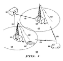
- the wireless communication system 100 incorporates a Central Control Switch or so-called Mobile Switching Centre (MSC) 110 and a number of remote Base Transceiver Stations (BTS) 120, 125 that are operably connected to MSC 110 via site links 115.
- MSC Mobile Switching Centre
- BTS Base Transceiver Stations
- a number of MS(s) (with only MS 140 shown for clarity purposes only) are able to move throughout the coverage area 130, 135.
- a single communication link consists of two frequencies: an outbound (downlink) frequency f 1 and an inbound (uplink) frequency f 2 , marked as 145 and 155 respectively, for communication in respective directions between the MS 140 and the BTS 125.
- Any wireless communication link i.e. link 145 or 155, is a potential subject to be jammed by interfering signal 170 generated by an adversary/jammer 160.
- the outbound link 145 from BTS 125 to MS 140 is a continuous signal while the inbound communication link 155 from the MS 140 to the BTS 125 uses burst transmissions.
- the inbound communication link 155 is considered to be more vulnerable, and is therefore the preferred target for jamming activity, due to the reduced transmission power and low antenna positioning of mobile communication units such as MS 140.
- a system is able to take if it is configured with the ability to detect jamming.
- a further per-user action performed in some systems includes re-locating a particular service to a different channel.
- These actions are typically implemented in point-to-point services such as telephony or individual calls, or packet data or any type of logical channel providing the ability to deliver specific control information.
- group-call communication such as Motorola's integrated digitally enhanced network (iDENTM), TETRA or the US APCO-25 standard, the actions may be performed on per group of users basis.
- the message indicates that the uplink transmission link is not available any more.
- the transmitting MS has previously successfully set up a session with the BTS prior to application of the jamming signal.
- the solution is only applicable to a specifically identified individual user and therefore all other MSs, including those being passive receivers, are not aware about the uplink status.
- a wireless communication system comprising at least one wireless serving communication unit serving a plurality of remote units with a communication resource.
- the at least one wireless serving communication unit comprises a transmitter for transmitting a signal to at least one of the plurality of remote units on an outbound communication resource, and a receiver for receiving communication from the at least one of the plurality of remote units on an inbound communication resource.
- the at least one wireless serving communication unit transmits a broadcast message on an outbound communication resource indicating a non-availability of one or more inbound communication resource(s).
- the message is sent in response to detection of non-availability of one or more inbound communication resource(s) owing to interference or jamming, e.g. as applied by a transmitter which is not part of the system with the intention of reducing the effectiveness of the system.
- the inventors of the present invention have proposed detection of non-availability of an uplink or inbound resource owing to interference or jamming and in response provision of a 'broadcast' transmission of indicating the unavailability of the uplink communication resource's non-availability to any MS currently using, or possibly subsequently using, the affected communication resource. This enables a delay of a communication service until the problem has been resolved and/or minimises impact of the uplink interference/jamming in subsequent call attempts by served MS(s).
- the 'broadcast' transmission of an uplink communication resource's non-availability comprises an indication of alternative communication resources (frequency and/or time) to be used.
- the wireless communication system may transmit a message to a MS indicating an uplink channel's unavailability. Notably, if this feature is supported in the wireless communication system, it is transmit using an 'individually-addressed' message. On receipt and processing of this message, the specifically-addressed MS is able to take appropriate action based on this knowledge.
- An embodiment of the present invention proposes that the transmission of such an 'uplink channel unavailability' message is performed using a specific 'broadcast address', which all MSs are configured to listen to. In this manner, the message is made available to all MSs allocated on, or directed to, that particular frequency.
- a trunked radio communication system 200 supporting a TErrestrial Trunked RAdio (TETRA) air-interface is shown in outline, in accordance with an embodiment of the invention.
- the European Telecommunications Standards Institute (ETSI) has defined the TETRA air interface.
- the air-interface protocol is administered from base sites that are geographically spaced apart - one base site supporting a cell or sectors of a cell.
- a plurality of subscriber units such as a mixture of MSs 212-216 and fixed terminals (not shown), communicate over a selected air-interface 218-220 with a plurality of serving base transceiver stations (BTS) 222-232.
- the BTSs 222-232 may be connected to a conventional public-switched telephone network (PSTN) 234 through base station controllers (BSCs) 236-240 and mobile switching centres (MSCs) 242-244.
- PSTN public-switched telephone network
- BSCs base station controllers
- MSCs mobile switching centres
- infrastructure elements including the BTS (sometimes referred to as a base station (BS)) may be grouped and defined as the Switching and Management Infrastructure (SwMI).
- BTS sometimes referred to as a base station (BS)
- SwMI Switching and Management Infrastructure
- the different terminology used should be considered as interchangeable.
- Each BSC 236-240 may control one or more BTSs 222-232, with BSCs 236-240 generally interconnected through MSCs 242-244. Each BSC 236-240 is therefore able to communicate with one another, if desired, to pass system administration information therebetween, with BSCs responsible for establishing and maintaining control channel and traffic channels to serviceable MSs affiliated therewith. The interconnection of BSCs therefore allows the trunked radio communication system to support handover of the MSs between cells.
- Each MSC 242-244 provides a gateway to the PSTN 234, with MSCs interconnected through an operations and management centre (OMC) 246 that administers general control of the trunked radio system 200, as will be understood by those skilled in the art.
- OMC operations and management centre
- the various system elements, such as BSCs 236-238 and OMC 246, will include control logic 248-252, with the various system elements usually having associated memory element 254 (shown only in relation to BSC 238 for the sake of clarity).
- the memory element 254 typically stores historically compiled operational data as well as in-call data, system information and control algorithms.
- one or more BTS(s) 222-232 have been adapted to implement the inventive concepts hereinafter described.
- One or more BTS(s), for example BTS 222 includes a controller and/or signal processor 221 that has been adapted to initiate a downlink 'broadcast' transmission of an 'uplink channel unavailable' message using a specific 'broadcast address'.
- a number (preferably all) MSs operating in the cell and supported by the one or more BTS are configured to listen to this specific 'broadcast address' to receive such a message. In this manner, the message is made available to all MSs listening to the specific 'broadcast address'.
- the 'uplink channel unavailable' message is sent using a low-level protocol message, for example a Medium Access Control (MAC) message, which is defined to contain a control flag/element (e.g. "Radio Uplink Failure") that indicates uplink unavailability of a particular channel.
- MAC Medium Access Control
- an MS On receipt and processing of this message, an MS is able to take appropriate action.
- the BTS is configured to continue to transmit the 'uplink channel unavailable' message periodically on the specific broadcast channel or to a broadcast address, whilst continuing to assess the uplink signal performance of the jammed/interfered channel, for example by examining the received signal strength and attempting to correctly decode any received signal on that channel.
- the system effectively reduces the number of transmission attempts on the jammed/unavailable channel.
- the one or more BTS(s) will continue to monitor the uplink channel and consider any non-decodable signal presence in the uplink channel as an interfering/jamming signal. As soon as the presence of an interfering/jamming signal ceases, the system will stop broadcasting the "uplink non-availability" message. Thus, the MSs will conclude that normal uplink performance has been resumed.
- BTS 222 BTS 222
- MS say MS 212
- BTS 222 BTS 222
- MS 212 MS 212
- new apparatus may be added to a conventional communication unit, or alternatively existing parts of a conventional communication unit may be adapted, for example by reprogramming one or more processors 211, 221 therein.
- the required adaptation may be implemented in the form of processor-implementable instructions stored on a storage medium, such as a floppy disk, hard disk, programmable read-only memory (PROM), random access memory (RAM) or any combination of these or other storage media.
- a storage medium such as a floppy disk, hard disk, programmable read-only memory (PROM), random access memory (RAM) or any combination of these or other storage media.
- a flowchart 300 illustrates an embodiment of a wireless communication system's operation.
- the flowchart commences in step 305 with the BTS continuously monitoring a performance of the uplink channels. This process continues as long as the BTS fails to detect jamming on one or more of the uplink channels, in step 310. However, once jamming is detected in step 310, for example by detecting a presence of a non-decodable signal, the BTS transmits a broadcast message that indicates there is a communication failure in one or more of the uplink channels, as shown in step 315.
- the BTS continues to monitor the uplink channels, particularly the one or more uplink channels that have been identified as faulty due to, say, being jammed or suffering interference from other RF transmissions, as in step 320. Whilst the one or more faulty/ jammed uplink channels continue(s) to be faulty/ jammed, in step 325, the process loops around steps 315, 320 and 325.
- any MSs allocated to, or arriving at, the frequency that has an interfered uplink channel will be able to recognise that the frequency is faulty/ jammed by decoding the broadcast message transmitted on the specific broadcast channel/frequency indicating the uplink failure conditions.
- the MS may initiate re-selection to a different cell.
- the MS may move to another frequency within the same cell.
- the MS may decide to remain on the jammed frequency if only downlink information and/or services are expected.
- step 325 If the one or more uplink channels identified as being faulty/jammed is subsequently found to be functioning correctly in step 325, the BTS halts its broadcast notification of that/those uplink failure(s), as shown in step 330. The process then reverts to step 305, for general BTS monitoring of uplink channels.
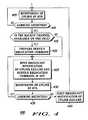
- step 405 commences in step 405 with the BTS continuously monitoring the uplink channels. This process continues as long as the BTS fails to detect jamming on one or more of the uplink channels, in step 410. However, once jamming is detected in step 410, for example by detecting a presence of a non-decodable signal, the BTS determines whether one or more back-up channels are available, as shown in step 415. If one or more back-up channels is/are available in step 415, the BTS prepares a service re-location command to broadcast to all served MS, as shown in step 420. If one or more back-up channels is/are not available in step 415, the process moves to step 425.
- the BTS then transmits a broadcast message that indicates there is a communication failure in one or more of the uplink channels, as shown in step 425.
- the broadcast message may be sent on a ⁇ per channel' basis, with the broadcast message sent on a current channel, indicating the unavailability of that appropriate uplink.
- the broadcast message in step 425 also includes any appropriate service re-location command, dependent upon the previous determination in step 415.
- the BTS continues to monitor the uplink channels, particularly the one or more uplink channels that have been identified as faulty due to, say, being jammed or suffering interference from other RF transmissions, as in step 430.
- the process Whilst the one or more faulty/jammed uplink channels continue(s) to be faulty/jammed, in step 435, the process loops around steps 425, 430 and 435. Otherwise, when jamming or interference is no longer detected, the broadcast transmission of an uplink failure message is halted, in step 440, and the process returns to step 405.
- the BTS is able to use the broadcast message in order to direct any interested MS(s) to the back-up channel if available.
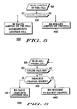
- a flowchart 500 illustrates an MS's operation in response to a 'broadcast' uplink-failure message, when attempting to register on a cell, in accordance with an embodiment of the present invention.
- the MS is attempting to register/camp on a cell, as shown in step 505.
- the MS halts the 'camping' process and may decide to re-select to another cell, as shown in step 515, in accordance with known cell-reselection techniques. Whilst the MS does not receive the uplink failure message in step 510, the MS continues to attempt to camp on the cell, as shown in step 520.
- the MS is able to adapt its registration process in a real-time manner dependent upon the information contained in the broadcast transmission received from the BTS.
- a flowchart 600 illustrates an MS's operation in response to an uplink failure indication when in 'idle' mode, in accordance with an embodiment of the present invention.
- the MS is in an 'idle' mode of operation, i.e. the MS is "camped" on the cell but not currently in service.
- the MS is able to continue monitoring the downlink channel.
- the MS determines whether a back-up channel exists, as shown in step 615. If a back-up channel does exist in step 615, the MS may decide to re-select to this back-up channel, as shown in step 625. Alternatively, if a back-up channel does not exist in step 615, the MS may decide to re-select to another cell, as shown in step 620.
- the MS may immediately switch to one of the back-up frequencies.
- the MS is able to postpone the transition until the moment it needs to send an uplink message.
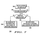
- flowchart 700 proposes that the BTS includes a 'channel allocation' element within the broadcast message.
- the preferred embodiment of the present invention uses a known TETRA MAC-RESOURCE PDU with a known "power Control information element "Radio Uplink Failure".
- the 'channel allocation' element serves as a notification of an alternative uplink channel to be used.
- a known TETRA MAC-RESOURSE PDU may be used with a known power control information element, i.e. "Radio Uplink Failure".
- this message is addressed to a broadcast address rather than to the individual MS, and preferably it still carries a channel allocation element.
- a channel allocation element is normally sent together with a Layer-3 PDU.
- a Layer-3 PDU allows routing of the information to a Layer-3 entity that decides whether service and channel allocations are accepted or rejected.
- Radio uplink failure and channel allocations will allow lower layers (e.g. MAC) to decide that service is re-located, without involving upper layers.
- lower layers e.g. MAC
- a new Layer-3 message e.g. a D-UPLINK-SERVICE PDU
- the new Layer-3 message would preferably contain a list of frequencies supported by the cell site together with a specific availability bit associated with each frequency and indicating its availability.
- a value "1" may be used to indicate an operational frequency
- a value "0" may be used to indicate that, for that specific frequency, the uplink channel is jammed and unreliable.
- this embodiment can be expanded to a D-NETWORK-BROADCAST PDU that is sent on the downlink channel and provides the information about the adjacent cells. In this case, it is envisaged that additional bits can be introduced into the message that will indicate those neighbouring cells that are experiencing a jamming attack.
- Flowchart 700 illustrates an MS's operation in response to an uplink failure message when in an 'active' mode of operation (step 705), in accordance with an embodiment of the present invention.
- the MS determines whether the broadcast message includes a 'service re-located' command, as shown in step 715. If the broadcast message includes a 'service re-located' command in step 715, the MS may decide to switch to the back-up channel and continue service, as shown in step 725. Alternatively, if the broadcast message does not include a 'service re-located' command in step 715, the MS may decide to re-select to another cell in order to restore service, as shown in step 720.
- the MS when the system supports 'service relocation' commands within a cell, for example where the command is broadcast within an uplink failure message, the MS is able to move to the back-up channel without a break in its service.
- the introduction of the inventive concepts described herein into most modern wireless communication systems can be implemented by re-programming of one or more processors within a BTS.
- the re-programming of the one or more processors comprise introducing a supplementary protocol allowing broadcast addressing of uplink failure conditions.
- a particular advantage of the proposed methods is the ability of the system to promptly respond to hostile or occasional interference (jamming) of the uplink channel, for example in FDD-type systems, thereby supporting increased service availability to the users.
- the invention has also been described with reference to an FDD-based communication system, where the interference occurs on one or more inbound frequency channels, it is envisaged that the same inventive concepts can be applied to alternative duplex technologies, such as a TDD-based system, where the interference occurs on one or more time slots/frames.
- the transmissions instead of providing broadcast transmissions on a particular frequency, the transmissions can be broadcast to MSs within one or more pre-defined time-slots or on one or more pre-defined time-slots on one or more particular frequencies.
- the messages may be transmitted in traffic or signalling channels, and may be included at various positions (header, data, tail, etc.) in, for example, a packet data transmission.
- the broadcast messages may be sent in a short message service format or on a broadcast paging channel or via any other appropriate means.
Applications Claiming Priority (2)
| Application Number | Priority Date | Filing Date | Title |
|---|---|---|---|
| GB0317373A GB2404306B (en) | 2003-07-25 | 2003-07-25 | Wireless communication system, communication unit and method of communication |
| GB0317373 | 2003-07-25 |
Publications (3)
| Publication Number | Publication Date |
|---|---|
| EP1501329A2 true EP1501329A2 (fr) | 2005-01-26 |
| EP1501329A3 EP1501329A3 (fr) | 2006-04-19 |
| EP1501329B1 EP1501329B1 (fr) | 2008-02-27 |
Family
ID=27772612
Family Applications (1)
| Application Number | Title | Priority Date | Filing Date |
|---|---|---|---|
| EP04102540A Not-in-force EP1501329B1 (fr) | 2003-07-25 | 2004-06-04 | Système de communication sans fil, unité de communication sans fil et procédé de réduction de l'impact des signaux de brouillage interférence |
Country Status (4)
| Country | Link |
|---|---|
| EP (1) | EP1501329B1 (fr) |
| AT (1) | ATE387823T1 (fr) |
| DE (1) | DE602004012028T2 (fr) |
| GB (1) | GB2404306B (fr) |
Cited By (3)
| Publication number | Priority date | Publication date | Assignee | Title |
|---|---|---|---|---|
| WO2007104009A3 (fr) * | 2006-03-08 | 2008-01-17 | Motorola Inc | Système de communications mobile et station mobile, station de base émettrice-réceptrice et procédé d'utilisation de ladite station |
| GB2481720A (en) * | 2010-07-02 | 2012-01-04 | Vodafone Plc | Radio access network monitors communication characteristics to identify interruptions, preferably related to jamming of security communications |
| EP2809022A1 (fr) * | 2013-05-27 | 2014-12-03 | Nokia Solutions and Networks Oy | Détection de brouillage radio intentionnel |
Citations (5)
| Publication number | Priority date | Publication date | Assignee | Title |
|---|---|---|---|---|
| GB2293523A (en) * | 1994-09-21 | 1996-03-27 | Motorola Ltd | Radio base station equipment with non-constant offset duplex trunking |
| US5708975A (en) * | 1994-06-06 | 1998-01-13 | Nokia Telecommunications Oy | Method for reacting to disturbance in a mobile communication system |
| EP1041836A2 (fr) * | 1999-03-31 | 2000-10-04 | Siemens Aktiengesellschaft | Procédé pour sélectionner une unité centrale de communication sans fil d'une pluralité d'unités centrales de communication |
| EP1304895A2 (fr) * | 2001-10-17 | 2003-04-23 | Motorola, Inc. | Emetteurs-récepteurs et procédé d'utilisation en communications radio |
| GB2384139A (en) * | 2002-01-15 | 2003-07-16 | Motorola Inc | Wireless communication system and method for use therein |
Family Cites Families (3)
| Publication number | Priority date | Publication date | Assignee | Title |
|---|---|---|---|---|
| US5896376A (en) * | 1996-12-13 | 1999-04-20 | Ericsson Inc. | Optimal use of logical channels within a mobile telecommunications network |
| KR100429540B1 (ko) * | 1998-08-26 | 2004-08-09 | 삼성전자주식회사 | 이동통신시스템의패킷데이터통신장치및방법 |
| CN1147204C (zh) * | 1999-08-03 | 2004-04-21 | 皇家菲利浦电子有限公司 | 用于在无线电通信系统中分配随机接入信道的方法与系统 |
-
2003
- 2003-07-25 GB GB0317373A patent/GB2404306B/en not_active Expired - Fee Related
-
2004
- 2004-06-04 AT AT04102540T patent/ATE387823T1/de not_active IP Right Cessation
- 2004-06-04 DE DE602004012028T patent/DE602004012028T2/de active Active
- 2004-06-04 EP EP04102540A patent/EP1501329B1/fr not_active Not-in-force
Patent Citations (5)
| Publication number | Priority date | Publication date | Assignee | Title |
|---|---|---|---|---|
| US5708975A (en) * | 1994-06-06 | 1998-01-13 | Nokia Telecommunications Oy | Method for reacting to disturbance in a mobile communication system |
| GB2293523A (en) * | 1994-09-21 | 1996-03-27 | Motorola Ltd | Radio base station equipment with non-constant offset duplex trunking |
| EP1041836A2 (fr) * | 1999-03-31 | 2000-10-04 | Siemens Aktiengesellschaft | Procédé pour sélectionner une unité centrale de communication sans fil d'une pluralité d'unités centrales de communication |
| EP1304895A2 (fr) * | 2001-10-17 | 2003-04-23 | Motorola, Inc. | Emetteurs-récepteurs et procédé d'utilisation en communications radio |
| GB2384139A (en) * | 2002-01-15 | 2003-07-16 | Motorola Inc | Wireless communication system and method for use therein |
Cited By (6)
| Publication number | Priority date | Publication date | Assignee | Title |
|---|---|---|---|---|
| WO2007104009A3 (fr) * | 2006-03-08 | 2008-01-17 | Motorola Inc | Système de communications mobile et station mobile, station de base émettrice-réceptrice et procédé d'utilisation de ladite station |
| KR101013261B1 (ko) * | 2006-03-08 | 2011-02-09 | 모토로라 인코포레이티드 | 이동 통신 시스템과 이동국, 기지 송수신국 및 그 이용 방법 |
| US8059619B2 (en) | 2006-03-08 | 2011-11-15 | Motorola Solutions, Inc. | Mobile communication system and a mobile station, a base transceiver station and a method for use therein |
| GB2481720A (en) * | 2010-07-02 | 2012-01-04 | Vodafone Plc | Radio access network monitors communication characteristics to identify interruptions, preferably related to jamming of security communications |
| GB2481720B (en) * | 2010-07-02 | 2014-02-12 | Vodafone Plc | Telecommunication networks |
| EP2809022A1 (fr) * | 2013-05-27 | 2014-12-03 | Nokia Solutions and Networks Oy | Détection de brouillage radio intentionnel |
Also Published As
| Publication number | Publication date |
|---|---|
| DE602004012028D1 (de) | 2008-04-10 |
| GB0317373D0 (en) | 2003-08-27 |
| EP1501329B1 (fr) | 2008-02-27 |
| DE602004012028T2 (de) | 2009-04-02 |
| GB2404306B (en) | 2005-08-31 |
| ATE387823T1 (de) | 2008-03-15 |
| EP1501329A3 (fr) | 2006-04-19 |
| GB2404306A (en) | 2005-01-26 |
Similar Documents
| Publication | Publication Date | Title |
|---|---|---|
| EP1090467B1 (fr) | Procede et appareil de transfert de communications a l'interieur d'un systeme de communication | |
| EP0948231B1 (fr) | Transfert de communication déclenché par l'intensité du signal reçu dans systèmes de communication sans fil | |
| EP0965187B1 (fr) | Système de communication radio utilisant sélectivement la multidiffusion avec un temps de déphasage variable | |
| US7003303B2 (en) | Dedicated high priority access channel | |
| EP1997253B1 (fr) | Système de communications mobile | |
| JP3395978B2 (ja) | 移動通信方式における無線網集中制御方法および装置 | |
| US6246886B1 (en) | System and methods for controlling access to digital wireless network in a dual mode wireless system | |
| US8583121B2 (en) | Mobile communication system, radio apparatus, and radio frequency change method | |
| US20070161374A1 (en) | Co-channel handover in a cellular network | |
| US7945263B2 (en) | Mobile station handover for base stations with adaptive antenna system | |
| CN102484830B (zh) | 用于呼叫重建的接入过程 | |
| US20020068569A1 (en) | Method and apparatus for flexible call recovery in a wireless communication system | |
| EP1032236A1 (fr) | Commande améliorée d'encombrement utilisant l'accès par catégories | |
| US6885866B1 (en) | Handover-method in a cellular radio system with two frequency bands | |
| EP1415486B1 (fr) | Transmission d'information de diffusion a une station mobile dans un systeme de radiocommunications | |
| WO1997044968A2 (fr) | Procede de transmission de donnees et appareil correspondant | |
| AU2002316956A1 (en) | Delivery of broadcast information to a mobile station in a radio communication system | |
| JP4344095B2 (ja) | データ伝送のための方法および無線通信システム | |
| WO2002017671A1 (fr) | Regulation de l'encombrement amelioree par utilisation de classes d'acces | |
| EP2048897B1 (fr) | Procédé pour réduire le risque de coupures d'appels dans un réseau de communication mobile | |
| EP1501329B1 (fr) | Système de communication sans fil, unité de communication sans fil et procédé de réduction de l'impact des signaux de brouillage interférence | |
| CN101938801A (zh) | 一种实现网络间重定位的方法及系统 | |
| WO2002030142A2 (fr) | Procede de traitement des appels de depart dans un systeme de telecommunications | |
| AU5039199A (en) | Handover-method in a cellular radio system | |
| EP1468509B1 (fr) | Espacement de frequences variable dans un systeme de communications duplex a repartition de frequences |
Legal Events
| Date | Code | Title | Description |
|---|---|---|---|
| PUAI | Public reference made under article 153(3) epc to a published international application that has entered the european phase |
Free format text: ORIGINAL CODE: 0009012 |
|
| AK | Designated contracting states |
Kind code of ref document: A2 Designated state(s): AT BE BG CH CY CZ DE DK EE ES FI FR GB GR HU IE IT LI LU MC NL PL PT RO SE SI SK TR |
|
| AX | Request for extension of the european patent |
Extension state: AL HR LT LV MK |
|
| PUAL | Search report despatched |
Free format text: ORIGINAL CODE: 0009013 |
|
| AK | Designated contracting states |
Kind code of ref document: A3 Designated state(s): AT BE BG CH CY CZ DE DK EE ES FI FR GB GR HU IE IT LI LU MC NL PL PT RO SE SI SK TR |
|
| AX | Request for extension of the european patent |
Extension state: AL HR LT LV MK |
|
| 17P | Request for examination filed |
Effective date: 20061019 |
|
| 17Q | First examination report despatched |
Effective date: 20061116 |
|
| AKX | Designation fees paid |
Designated state(s): AT BE BG CH CY CZ DE DK EE ES FI FR GB GR HU IE IT LI LU MC NL PL PT RO SE SI SK TR |
|
| GRAP | Despatch of communication of intention to grant a patent |
Free format text: ORIGINAL CODE: EPIDOSNIGR1 |
|
| GRAS | Grant fee paid |
Free format text: ORIGINAL CODE: EPIDOSNIGR3 |
|
| GRAA | (expected) grant |
Free format text: ORIGINAL CODE: 0009210 |
|
| AK | Designated contracting states |
Kind code of ref document: B1 Designated state(s): AT BE BG CH CY CZ DE DK EE ES FI FR GB GR HU IE IT LI LU MC NL PL PT RO SE SI SK TR |
|
| REG | Reference to a national code |
Ref country code: GB Ref legal event code: FG4D |
|
| REG | Reference to a national code |
Ref country code: CH Ref legal event code: EP |
|
| REG | Reference to a national code |
Ref country code: IE Ref legal event code: FG4D |
|
| REF | Corresponds to: |
Ref document number: 602004012028 Country of ref document: DE Date of ref document: 20080410 Kind code of ref document: P |
|
| PG25 | Lapsed in a contracting state [announced via postgrant information from national office to epo] |
Ref country code: ES Free format text: LAPSE BECAUSE OF FAILURE TO SUBMIT A TRANSLATION OF THE DESCRIPTION OR TO PAY THE FEE WITHIN THE PRESCRIBED TIME-LIMIT Effective date: 20080607 Ref country code: FI Free format text: LAPSE BECAUSE OF FAILURE TO SUBMIT A TRANSLATION OF THE DESCRIPTION OR TO PAY THE FEE WITHIN THE PRESCRIBED TIME-LIMIT Effective date: 20080227 |
|
| NLV1 | Nl: lapsed or annulled due to failure to fulfill the requirements of art. 29p and 29m of the patents act | ||
| PG25 | Lapsed in a contracting state [announced via postgrant information from national office to epo] |
Ref country code: AT Free format text: LAPSE BECAUSE OF FAILURE TO SUBMIT A TRANSLATION OF THE DESCRIPTION OR TO PAY THE FEE WITHIN THE PRESCRIBED TIME-LIMIT Effective date: 20080227 |
|
| PG25 | Lapsed in a contracting state [announced via postgrant information from national office to epo] |
Ref country code: PL Free format text: LAPSE BECAUSE OF FAILURE TO SUBMIT A TRANSLATION OF THE DESCRIPTION OR TO PAY THE FEE WITHIN THE PRESCRIBED TIME-LIMIT Effective date: 20080227 Ref country code: SI Free format text: LAPSE BECAUSE OF FAILURE TO SUBMIT A TRANSLATION OF THE DESCRIPTION OR TO PAY THE FEE WITHIN THE PRESCRIBED TIME-LIMIT Effective date: 20080227 Ref country code: BE Free format text: LAPSE BECAUSE OF FAILURE TO SUBMIT A TRANSLATION OF THE DESCRIPTION OR TO PAY THE FEE WITHIN THE PRESCRIBED TIME-LIMIT Effective date: 20080227 |
|
| PG25 | Lapsed in a contracting state [announced via postgrant information from national office to epo] |
Ref country code: DK Free format text: LAPSE BECAUSE OF FAILURE TO SUBMIT A TRANSLATION OF THE DESCRIPTION OR TO PAY THE FEE WITHIN THE PRESCRIBED TIME-LIMIT Effective date: 20080227 Ref country code: NL Free format text: LAPSE BECAUSE OF FAILURE TO SUBMIT A TRANSLATION OF THE DESCRIPTION OR TO PAY THE FEE WITHIN THE PRESCRIBED TIME-LIMIT Effective date: 20080227 Ref country code: SE Free format text: LAPSE BECAUSE OF FAILURE TO SUBMIT A TRANSLATION OF THE DESCRIPTION OR TO PAY THE FEE WITHIN THE PRESCRIBED TIME-LIMIT Effective date: 20080527 Ref country code: SK Free format text: LAPSE BECAUSE OF FAILURE TO SUBMIT A TRANSLATION OF THE DESCRIPTION OR TO PAY THE FEE WITHIN THE PRESCRIBED TIME-LIMIT Effective date: 20080227 Ref country code: CZ Free format text: LAPSE BECAUSE OF FAILURE TO SUBMIT A TRANSLATION OF THE DESCRIPTION OR TO PAY THE FEE WITHIN THE PRESCRIBED TIME-LIMIT Effective date: 20080227 Ref country code: PT Free format text: LAPSE BECAUSE OF FAILURE TO SUBMIT A TRANSLATION OF THE DESCRIPTION OR TO PAY THE FEE WITHIN THE PRESCRIBED TIME-LIMIT Effective date: 20080721 |
|
| ET | Fr: translation filed | ||
| PG25 | Lapsed in a contracting state [announced via postgrant information from national office to epo] |
Ref country code: RO Free format text: LAPSE BECAUSE OF FAILURE TO SUBMIT A TRANSLATION OF THE DESCRIPTION OR TO PAY THE FEE WITHIN THE PRESCRIBED TIME-LIMIT Effective date: 20080227 |
|
| PLBE | No opposition filed within time limit |
Free format text: ORIGINAL CODE: 0009261 |
|
| STAA | Information on the status of an ep patent application or granted ep patent |
Free format text: STATUS: NO OPPOSITION FILED WITHIN TIME LIMIT |
|
| PG25 | Lapsed in a contracting state [announced via postgrant information from national office to epo] |
Ref country code: MC Free format text: LAPSE BECAUSE OF NON-PAYMENT OF DUE FEES Effective date: 20080630 |
|
| REG | Reference to a national code |
Ref country code: CH Ref legal event code: PL |
|
| 26N | No opposition filed |
Effective date: 20081128 |
|
| PG25 | Lapsed in a contracting state [announced via postgrant information from national office to epo] |
Ref country code: IE Free format text: LAPSE BECAUSE OF NON-PAYMENT OF DUE FEES Effective date: 20080604 Ref country code: BG Free format text: LAPSE BECAUSE OF FAILURE TO SUBMIT A TRANSLATION OF THE DESCRIPTION OR TO PAY THE FEE WITHIN THE PRESCRIBED TIME-LIMIT Effective date: 20080527 Ref country code: EE Free format text: LAPSE BECAUSE OF FAILURE TO SUBMIT A TRANSLATION OF THE DESCRIPTION OR TO PAY THE FEE WITHIN THE PRESCRIBED TIME-LIMIT Effective date: 20080227 |
|
| PG25 | Lapsed in a contracting state [announced via postgrant information from national office to epo] |
Ref country code: LI Free format text: LAPSE BECAUSE OF NON-PAYMENT OF DUE FEES Effective date: 20080630 Ref country code: CH Free format text: LAPSE BECAUSE OF NON-PAYMENT OF DUE FEES Effective date: 20080630 |
|
| PG25 | Lapsed in a contracting state [announced via postgrant information from national office to epo] |
Ref country code: CY Free format text: LAPSE BECAUSE OF FAILURE TO SUBMIT A TRANSLATION OF THE DESCRIPTION OR TO PAY THE FEE WITHIN THE PRESCRIBED TIME-LIMIT Effective date: 20080227 |
|
| PG25 | Lapsed in a contracting state [announced via postgrant information from national office to epo] |
Ref country code: IT Free format text: LAPSE BECAUSE OF FAILURE TO SUBMIT A TRANSLATION OF THE DESCRIPTION OR TO PAY THE FEE WITHIN THE PRESCRIBED TIME-LIMIT Effective date: 20080227 |
|
| PG25 | Lapsed in a contracting state [announced via postgrant information from national office to epo] |
Ref country code: LU Free format text: LAPSE BECAUSE OF NON-PAYMENT OF DUE FEES Effective date: 20080604 Ref country code: HU Free format text: LAPSE BECAUSE OF FAILURE TO SUBMIT A TRANSLATION OF THE DESCRIPTION OR TO PAY THE FEE WITHIN THE PRESCRIBED TIME-LIMIT Effective date: 20080828 |
|
| PG25 | Lapsed in a contracting state [announced via postgrant information from national office to epo] |
Ref country code: TR Free format text: LAPSE BECAUSE OF FAILURE TO SUBMIT A TRANSLATION OF THE DESCRIPTION OR TO PAY THE FEE WITHIN THE PRESCRIBED TIME-LIMIT Effective date: 20080227 |
|
| PG25 | Lapsed in a contracting state [announced via postgrant information from national office to epo] |
Ref country code: GR Free format text: LAPSE BECAUSE OF FAILURE TO SUBMIT A TRANSLATION OF THE DESCRIPTION OR TO PAY THE FEE WITHIN THE PRESCRIBED TIME-LIMIT Effective date: 20080528 |
|
| REG | Reference to a national code |
Ref country code: FR Ref legal event code: CD |
|
| REG | Reference to a national code |
Ref country code: DE Ref legal event code: R082 Ref document number: 602004012028 Country of ref document: DE Representative=s name: SCHUMACHER & WILLSAU PATENTANWALTSGESELLSCHAFT, DE |
|
| REG | Reference to a national code |
Ref country code: DE Ref legal event code: R081 Ref document number: 602004012028 Country of ref document: DE Owner name: MOTOROLA SOLUTIONS ISRAEL LTD., IL Free format text: FORMER OWNER: MOTOROLA SOLUTIONS, INC., SCHAUMBURG, US Effective date: 20120229 Ref country code: DE Ref legal event code: R081 Ref document number: 602004012028 Country of ref document: DE Owner name: MOTOROLA SOLUTIONS ISRAEL LTD., IL Free format text: FORMER OWNER: MOTOROLA INC., SCHAUMBURG, US Effective date: 20120113 Ref country code: DE Ref legal event code: R082 Ref document number: 602004012028 Country of ref document: DE Representative=s name: SCHUMACHER & WILLSAU PATENTANWALTSGESELLSCHAFT, DE Effective date: 20120113 Ref country code: DE Ref legal event code: R082 Ref document number: 602004012028 Country of ref document: DE Representative=s name: SCHUMACHER & WILLSAU PATENTANWALTSGESELLSCHAFT, DE Effective date: 20120229 Ref country code: DE Ref legal event code: R081 Ref document number: 602004012028 Country of ref document: DE Owner name: MOTOROLA SOLUTIONS ISRAEL LTD., IL Free format text: FORMER OWNER: MOTOROLA SOLUTIONS, INC., SCHAUMBURG, ILL., US Effective date: 20120229 Ref country code: DE Ref legal event code: R081 Ref document number: 602004012028 Country of ref document: DE Owner name: MOTOROLA SOLUTIONS ISRAEL LTD., IL Free format text: FORMER OWNER: MOTOROLA INC., SCHAUMBURG, ILL., US Effective date: 20120113 |
|
| REG | Reference to a national code |
Ref country code: FR Ref legal event code: TP Owner name: MOTOROLA SOLUTIONS ISRAEL LIMITED, IL Effective date: 20120321 |
|
| REG | Reference to a national code |
Ref country code: GB Ref legal event code: 732E Free format text: REGISTERED BETWEEN 20120419 AND 20120425 |
|
| REG | Reference to a national code |
Ref country code: FR Ref legal event code: PLFP Year of fee payment: 13 |
|
| REG | Reference to a national code |
Ref country code: FR Ref legal event code: PLFP Year of fee payment: 14 |
|
| REG | Reference to a national code |
Ref country code: FR Ref legal event code: PLFP Year of fee payment: 15 |
|
| PGFP | Annual fee paid to national office [announced via postgrant information from national office to epo] |
Ref country code: FR Payment date: 20200626 Year of fee payment: 17 |
|
| PG25 | Lapsed in a contracting state [announced via postgrant information from national office to epo] |
Ref country code: FR Free format text: LAPSE BECAUSE OF NON-PAYMENT OF DUE FEES Effective date: 20210630 |
|
| PGFP | Annual fee paid to national office [announced via postgrant information from national office to epo] |
Ref country code: GB Payment date: 20220621 Year of fee payment: 19 |
|
| PGFP | Annual fee paid to national office [announced via postgrant information from national office to epo] |
Ref country code: DE Payment date: 20220628 Year of fee payment: 19 |
|
| P01 | Opt-out of the competence of the unified patent court (upc) registered |
Effective date: 20230529 |
|
| REG | Reference to a national code |
Ref country code: DE Ref legal event code: R119 Ref document number: 602004012028 Country of ref document: DE |
|
| GBPC | Gb: european patent ceased through non-payment of renewal fee |
Effective date: 20230604 |
|
| PG25 | Lapsed in a contracting state [announced via postgrant information from national office to epo] |
Ref country code: DE Free format text: LAPSE BECAUSE OF NON-PAYMENT OF DUE FEES Effective date: 20240103 Ref country code: GB Free format text: LAPSE BECAUSE OF NON-PAYMENT OF DUE FEES Effective date: 20230604 |