EP1501262B1 - Polstervorrichtung einer Baugruppe für ein Mobilfunkgeràt - Google Patents
Polstervorrichtung einer Baugruppe für ein Mobilfunkgeràt Download PDFInfo
- Publication number
- EP1501262B1 EP1501262B1 EP04254218A EP04254218A EP1501262B1 EP 1501262 B1 EP1501262 B1 EP 1501262B1 EP 04254218 A EP04254218 A EP 04254218A EP 04254218 A EP04254218 A EP 04254218A EP 1501262 B1 EP1501262 B1 EP 1501262B1
- Authority
- EP
- European Patent Office
- Prior art keywords
- spacer
- component assembly
- housing
- layer
- mobile device
- Prior art date
- Legal status (The legal status is an assumption and is not a legal conclusion. Google has not performed a legal analysis and makes no representation as to the accuracy of the status listed.)
- Expired - Lifetime
Links
- 125000006850 spacer group Chemical group 0.000 claims abstract description 97
- 238000003780 insertion Methods 0.000 claims abstract description 7
- 230000037431 insertion Effects 0.000 claims abstract description 7
- 239000006260 foam Substances 0.000 claims description 8
- 238000004519 manufacturing process Methods 0.000 claims description 6
- 239000004973 liquid crystal related substance Substances 0.000 claims description 3
- 238000000034 method Methods 0.000 claims description 3
- 238000000151 deposition Methods 0.000 claims description 2
- 238000003892 spreading Methods 0.000 claims description 2
- 239000000463 material Substances 0.000 abstract description 25
- 230000006835 compression Effects 0.000 description 26
- 238000007906 compression Methods 0.000 description 26
- 230000002093 peripheral effect Effects 0.000 description 4
- 230000035939 shock Effects 0.000 description 4
- 238000004891 communication Methods 0.000 description 3
- 230000001413 cellular effect Effects 0.000 description 2
- 230000007423 decrease Effects 0.000 description 2
- 238000006073 displacement reaction Methods 0.000 description 2
- 230000013011 mating Effects 0.000 description 2
- 230000004075 alteration Effects 0.000 description 1
- 230000000694 effects Effects 0.000 description 1
- 238000005516 engineering process Methods 0.000 description 1
- 239000006261 foam material Substances 0.000 description 1
- 238000007373 indentation Methods 0.000 description 1
- 239000007788 liquid Substances 0.000 description 1
- 239000006193 liquid solution Substances 0.000 description 1
- 238000012986 modification Methods 0.000 description 1
- 230000004048 modification Effects 0.000 description 1
- 238000006467 substitution reaction Methods 0.000 description 1
Images





Classifications
-
- H—ELECTRICITY
- H04—ELECTRIC COMMUNICATION TECHNIQUE
- H04M—TELEPHONIC COMMUNICATION
- H04M1/00—Substation equipment, e.g. for use by subscribers
- H04M1/02—Constructional features of telephone sets
- H04M1/0202—Portable telephone sets, e.g. cordless phones, mobile phones or bar type handsets
- H04M1/026—Details of the structure or mounting of specific components
- H04M1/0277—Details of the structure or mounting of specific components for a printed circuit board assembly
-
- H—ELECTRICITY
- H04—ELECTRIC COMMUNICATION TECHNIQUE
- H04M—TELEPHONIC COMMUNICATION
- H04M1/00—Substation equipment, e.g. for use by subscribers
- H04M1/02—Constructional features of telephone sets
-
- H—ELECTRICITY
- H05—ELECTRIC TECHNIQUES NOT OTHERWISE PROVIDED FOR
- H05K—PRINTED CIRCUITS; CASINGS OR CONSTRUCTIONAL DETAILS OF ELECTRIC APPARATUS; MANUFACTURE OF ASSEMBLAGES OF ELECTRICAL COMPONENTS
- H05K7/00—Constructional details common to different types of electric apparatus
- H05K7/02—Arrangements of circuit components or wiring on supporting structure
- H05K7/12—Resilient or clamping means for holding component to structure
-
- H—ELECTRICITY
- H05—ELECTRIC TECHNIQUES NOT OTHERWISE PROVIDED FOR
- H05K—PRINTED CIRCUITS; CASINGS OR CONSTRUCTIONAL DETAILS OF ELECTRIC APPARATUS; MANUFACTURE OF ASSEMBLAGES OF ELECTRICAL COMPONENTS
- H05K7/00—Constructional details common to different types of electric apparatus
- H05K7/14—Mounting supporting structure in casing or on frame or rack
- H05K7/1417—Mounting supporting structure in casing or on frame or rack having securing means for mounting boards, plates or wiring boards
-
- H—ELECTRICITY
- H04—ELECTRIC COMMUNICATION TECHNIQUE
- H04M—TELEPHONIC COMMUNICATION
- H04M1/00—Substation equipment, e.g. for use by subscribers
- H04M1/72—Mobile telephones; Cordless telephones, i.e. devices for establishing wireless links to base stations without route selection
- H04M1/725—Cordless telephones
Definitions
- the present invention relates to a mobile devices and particularly, to a device for cushioning a component assembly in a mobile device.
- a typical component assembly is a component stack that includes a display, such as a liquid crystal display (LCD) and a circuit board.
- LCD liquid crystal display
- the housing consists of two mating halves to contain the assembly.
- the mated halves define an interior cavity and, of course, the depth of the component assembly must be slightly less than the depth of the interior cavity. The difference in depth results in an undesirable gap between the component assembly and the housing inside the assembled device.
- the gap can be expected to vary in depth due to manufacturing tolerances, assembly tolerances, substitution of components in the component assembly, redesign of the component assembly or the use of a standard housing for different models or devices.
- the gap is undesirable since it can result in movement or play of the interior components of the device allowing components to become displaced, disconnected, damaged or simply rattle around inside the housing, especially if the device suffers a shock such as from being dropped.
- one solution is to employ a cushion or spacer, for example, a layer of compressible foam.
- the uncompressed spacer is deeper than the dimension of the gap so that when the depth of the spacer is added to the depth of the component assembly, the total depth is greater than that of the to the depth of the component assembly, the total depth is greater than that of the interior of the housing.
- the interior of the housing comes into contact with the spacer and compresses it against the component stack. Accordingly, the gap is occupied by the compressed spacer preventing movement of the component assembly in the direction of the stack-up (normal to the plane of the circuit board or the LCD).
- the spacer If the spacer is insufficiently deep, it will not span the gap even in an uncompressed state or it will provide inadequate cushioning for the component assembly. If the spacer is too deep then upon compression it will expert excessive pressure to the component assembly including the display. In the situation where the display is an LCD module, the LCD itself is sensitive to the pressure applied to it. Pushing it unevenly or with too much force will cause a blemish or distortion to appear in the viewing area. Excessive pressure can also prevent the spacer from property dispersing the energy of an impact because its ability to deflect has already been used in taking up the tolerance of the small available space and in extreme cases excessive pressure or the inability to deflect a shock can result in breaking of the screen. This is very costly, especially if the screen is an expensive colour LCD,
- US 5,548,430 discloses a flickerproof retaining structure for a liquid crystal display comprising an elastic pad disposed under a lower face of the display and a peripheral supporting frame located under the elastic pad to support the same.
- the peripheral supporting frame is formed on a housing and profiled corresponding to a peripheral scaled portion or the display.
- the peripheral supporting frame has an upper edge portion supporting and abutting against a bottom face of the scaled portion of the display.
- a spacer for use in a mobile device to space a component assembly from a housing of the mobile device.
- the spacer comprises a body of compressible material for insertion between the component assembly and the housing, and a plurality of compressible features provided on the body.
- the compressible features deform to prevent displacement of the component assembly relative to the housing while leaving the body of the spacer relatively uncompressed so that the body cushions the component assembly.
- a spacer for use in a mobile device.
- the spacer fills a space between a component assembly and a housing.
- the component assembly includes a display component.
- the spacer comprises a layer of compressible material for insertion between the component assembly and the housing; and a plurality of compressible features provided on a face of the layer.
- the compressible features are compressible upon assembly of the mobile device and extend between the component assembly and the housing to space the component assembly inside the housing when the mobile device is assembled.
- the depth of the layer and uncompressed compressible features exceeds the depth of the space between the component assembly and the housing, and the depth of the compressed layer and the compressed compressible features exceeds a predetermined critical depth.
- a method of manufacturing a spacer for use in a mobile device includes a body of compressible material for insertion between a component assembly of the mobile device and a housing of the mobile device; and a plurality of compressible features are provided on the body for filling space between the component assembly and the housing during assembly of the mobile device while leaving the body of the spacer relatively uncompressed so that the body can cushion the component assembly.
- the method comprises steps of depositing partially cured solution of material onto a surface; spreading the partially cured solution of material to form a layer of desired thickness; using a patterned roller to flatten and pattern the spread partially cured solution of material; and allowing the partially cured solution of material to cure.
- a spacer for use with a mobile device having a component assembly enclosed in a housing is provided.
- the spacer occupies a gap between the component assembly and the housing.
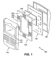
- a mobile device 100 has a component assembly or component stack contained within a housing.
- the mobile device 100 is an electronic device such as a hand-held computer, a cellular telephone with or without data communications functionality, a wireless mobile data communication device, a wireless email communication device, a pager, or a PDA, for example.
- the housing of Figure 1 consists of two mating halves, a front half 110 and a back half 150 . When the front and back halves are assembled, they define the housing and an interior cavity.
- the component assembly includes electronic circuitry 140 , for example, a circuit board and a display such as an LCD 130 .
- a seal or spacer 120 according to an embodiment of the present invention is used to eliminate any gap between the housing and the component assembly in the direction of the stack-up (normal to the plane of the circuit board 140 ).
- the spacer 120 is made of a suitable material such as compressible foam.
- the body 122 of the spacer is a layer of compressible material, such as a foam material, dimensioned to extend around the perimeter of the cavity at the front or back half of the housing.
- a central aperture 126 in the body enables the LCD 130 to be visible through a window 112 in the front of the housing.
- the central aperture also allows actuators 114 to contact or connect with corresponding elements on the circuit board 140 .
- Compressible features such as the raised feature 124 are provided on the front surface of the spacer. These compressible features make the spacer or seal hyperelastic as explained below.
- the raised features 124 illustrated in Figure 1 are domed, although they can be any suitable shape such as cylindrical, polygonal prism, conical, frusto-conical, pyramidal and frusto-pyramidal. Alternatively, a pattern of recesses, valleys or dimples can be cut, stamped or otherwise formed into the surface of the spacer, leaving compressible features (e.g. ridges surrounding the cut out portions) formed on the underlying body layer.
- the raised features 124 form a regular grid or arrayed pattern, however, any suitable pattern can be used.
- the planar density of compressible features can also be varied, for example by the pattern chosen, as discussed below.
- the raised features 124 can be made of a material different than that of the spacer but, according to a preferred embodiment, they are integrally formed with the spacer.
- the raised features 124 enable the spacer to accommodate larger gaps than a conventional spacer without over compressing the LCD 130 in smaller gaps.
- the raised features 124 deflect with minimal force since the volume of the raised features 124 of the spacer 120 is small. See region 910 in Figure 9 . Without the raised features 124 there could be a gap or inadequate cushioning between the housing and the assembly. The raised features 124 overcome the tolerance or gap without affecting the range of the work area of the spacer 120 . This makes the full compression range of at least the body 122 of the spacer 120 available for cushioning the component assembly. The component assembly will have neither pre-compression set nor play.
- Figure 11a illustrates a conventional spacer 1120 having thickness t.
- the range will vary depending on many factors, including the properties of the material of the spacer and the geometry of the spacer, component stack and housing.
- the spacer 1120 cannot accommodate gap g1 where g1 > t.
- the spacer 1120 cannot accommodate too small a gap g2 which overcompresses the spacer.
- the spacer 1120 can only accommodate gaps smaller than its thickness, i.e. g ⁇ t, and if the acceptable maximum compression is 10% then the spacer can only accommodate gaps larger than (1-0.1)t, or g > 0.9t. Accordingly, for a conventional spacer such as the spacer 1120 , 0.9t ⁇ g ⁇ t, or more generally (1-c)t ⁇ g ⁇ t, where g is the size of the gap, t is the thickness of the spacer and c is the maximum acceptable amount of compression and 0 ⁇ c ⁇ 1.
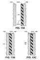
- a spacer 1210 includes a main body 1212 with thickness t and protrusions 1214 with thickness h. Assuming that the volume of material in the protrusions is small compared with the volume of material in the body, then the protrusions will be nearly completely collapsed before any substantial compression of the body 1212 occurs, as shown in Figures 13a to 13c . When the protrusions are partially compressed, a compression force is exerted on the component stack preventing it from moving in the stack direction.
- any gap which satisfies g ⁇ t+h and g>(1-c)t can be accommodated, or (1-c)t ⁇ g ⁇ t+h.
- the spacer 1210 accommodates a greater range of gaps, including gaps up to a size of t+h instead of gaps up to size t, without affecting the compression limit c.
- the ratio of h to t is important, and selected for a desired gap range. For example, the increase in gap range is very significant if h/t is close to 1.
- the maximum amount of compression expressed in terms of the total thickness of the spacer, can vary substantially.
- the maximum amount of compression, c is in the range 3% to 10%.
- c is in the range 4% to 6%.
- c is approximately 5%.
- a spacer includes a spacer having a body and layer of compressible features provided on the body.
- the body and the layer of compressible features have different compression properties.
- the body is relatively resistant to compression and the layer of compressible features is relatively easy to compress.
- This arrangement can be effected by using different materials or by using the same materials for differently formed structures or differently dimensioned structures as in the examples above.
- the body comprises a first layer relatively resistant to compression and the protrusions form a sparse second layer of material that is relatively compressible.
- the relatively compressible layer is formed of a layer similar to the body layer but having depressions, cut-outs, grooves or other volumes of material removed so that the total volume of material compressed is less than the volume of material compressed in a like volume of space.
- Spacers according to aspects of the present invention have different physical characteristics than a conventional spacer. This is illustrated in Figure 10 .
- a conventional spacer without raised features has the compression curve 1010 whereas a spacer according to an embodiment of the present invention has compression curve 1020 .
- Figure 2 illustrates another embodiment of the present invention, in which a spacer 200 includes a body 220 having raised features 222 that are differently spaced than in the preceding embodiment shown in Figure 1 .
- Figures 3 and 4 illustrate still another embodiment wherein a spacer 300 has a different pattern of raised features 310 on the body 320 .
- FIG. 5 an alternative embodiment of the present invention is illustrated in which a front spacer 120 and a back spacer 510 are employed, corresponding to each of the two halves 110 and 150 of the housing. This provides additional protection for the components and enables larger tolerances to be overcome.
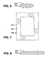
- the spacer 600 has raised features 610 on both its surfaces. Again, this increases the amount of tolerance which can be accommodated by the spacer.
- Figure 7 illustrates another pattern of raised features 710 which are less densely spaced on the body 720 of the spacer 700 than the raised features of Figure 1 . This decreases the volume of spacer 700 to be compressed and decreases the associated pressure.
- the pattern of compressible features can be more densely spaced to increase the volume of material initially compressed and increase the pressure.
- Figure 8 illustrates compressible features 810 of varying heights that modify the compression curve of the spacer 800 over its area.
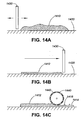
- FIGs 14 and 15 An example method of manufacturing the spacer of the present invention is illustrated in Figures 14 and 15 .
- a mass 1410 of liquid solution of rubber or other suitable material is deposited on a plate 1420 , as shown in Figure 14a .
- an oscillating blade 1430 spreads the rubber solution 1410 over the plate 1420 to achieve a layer of rubber 1412 in a half-liquid state, as in Figure 14b .
- the layer is approximately twice the thickness of the final spacer, although this can be varied as required.
- a master roll 1440 is then used to flatten and pattern the rubber 1412 and produce a mass of material 1414 of the desired thickness, for example, 0.787 mm not including the thickness of the raised features 1416 .
- the material is allowed to cure, and is then trimmed to form one or more rolls which can be cut as desired into individual spacers.
- Figure 15 illustrates an example embodiment of a master roll 1440 having indentations 1442 which result in the raised features 1416 .
- master rolls are used to produce different shapes or patterns of raised features, or to effect dimples or cut outs in a material roll for spacers.
Landscapes
- Engineering & Computer Science (AREA)
- Microelectronics & Electronic Packaging (AREA)
- Signal Processing (AREA)
- Devices For Indicating Variable Information By Combining Individual Elements (AREA)
- Telephone Set Structure (AREA)
- Vibration Dampers (AREA)
- Fittings On The Vehicle Exterior For Carrying Loads, And Devices For Holding Or Mounting Articles (AREA)
- Structure Of Receivers (AREA)
- Liquid Crystal (AREA)
- Packaging Of Machine Parts And Wound Products (AREA)
- Buffer Packaging (AREA)
Claims (9)
- Füllkörper (120) zur Verwendung in einer mobilen Vorrichtung (100), wobei der Füllkörper vorgesehen ist zum Füllen eines Raums zwischen einer Komponentenanordnung und einem Gehäuse (110), wobei die Komponentenanordnung eine Anzeigekomponente aufweist, wobei der Füllkörper aufweist:eine Schicht aus Schaumstoff zum Einfügen zwischen der Komponentenanordnung und dem Gehäuse; undeine Vielzahl von erhabenen gewölbten Merkmalen (124), vorgesehen auf einer Fläche der Schicht, wobei die erhabenen gewölbten Merkmale komprimierbar sind bei Zusammenbau der mobilen Vorrichtung und sich zwischen der Komponentenanordnung und dem Gehäuse erstrecken, um die Komponentenanordnung im Inneren des Gehäuses mit Abstand zu versehen, wenn die mobile Vorrichtung zusammengebaut wird, und die Dicke der Schicht und die nicht komprimierten erhabenen gewölbten Merkmale die Tiefe des Raums zwischen der Komponentenanordnung und dem Gehäuse übersteigen, und die Dicke der komprimierten Schicht und die komprimierten erhabenen gewölbten Merkmale eine vorgegebene kritische Dicke übersteigen.
- Füllkörper gemäß Anspruch 1, wobei die erhabenen gewölbten Merkmale in der Form gewölbt, zylinderförmig, polygonales Prisma, konisch, kegelstumpfförmig, pyramidenförmig oder stumpf-pyramidenförmig sind.
- Füllkörper gemäß Anspruch 1, wobei die erhabenen gewölbten Merkmale in der Dicke einheitlich sind.
- Füllkörper gemäß Anspruch 1, wobei die erhabenen gewölbten Merkmale auf gegenüberliegenden Seiten der Schicht vorgesehen sind.
- Füllkörper gemäß Anspruch 1, wobei die erhabenen gewölbten Merkmale in Gruppen gebündelt sind, die mit Abstand zueinander angeordnet sind.
- Füllkörper gemäß Anspruch 1, wobei die Schicht mit einer Öffnung (126) vorgesehen ist, um die Anzeigekomponente freizugeben.
- Füllkörper gemäß Anspruch 6, wobei die Anzeigekomponente eine ist aus:einer Flüssigkristallanzeige, einer Plasmaanzeige, einer Leuchtdiodenanzeige und einer organischen Anzeige.
- Füllkörper gemäß Anspruch 1, wobei die erhabenen gewölbten Merkmale ein Gittermuster bilden.
- Verfahren zum Herstellen eines Füllkörpers (120) zur Verwendung in einer mobilen Vorrichtung (100), wobei der Füllkörper eine Schicht (122) aus Schaumstoff zum Einfügen zwischen einer Komponentenanordnung der mobilen Vorrichtung und einem Gehäuse (110) der mobilen Vorrichtung umfasst; und eine Vielzahl von erhabenen gewölbten Merkmalen (124), die auf der Schicht vorgesehen sind zum Ausfüllen eines Raums zwischen der Komponentenanordnung und dem Gehäuse während der Herstellung der mobilen Vorrichtung und die Schicht des Füllkörpers relativ unkomprimiert lassen, so dass die Schicht die Komponentenanordnung polstern kann, wobei das Verfahren aufweist:Aufbringen einer teilweise ausgehärteten Lösung aus Schaumstoff auf eine Oberfläche;Auftragen der teilweise ausgehärteten Lösung aus Schaumstoff, um eine Schicht gewünschter Dicke zu bilden;Verwenden eines gemusterten Rollers, um die aufgetragene teilweise ausgehärtete Lösung aus Schaumstoff zu glätten und mit einem Muster zu versehen, um erhabene gewölbte Merkmale zu umfassen; undErmöglichen einer Aushärtung der teilweise ausgehärteten Lösung aus Schaumstoff.
Priority Applications (1)
| Application Number | Priority Date | Filing Date | Title |
|---|---|---|---|
| EP09161854A EP2091213B1 (de) | 2003-07-14 | 2004-07-14 | Polstervorrichtung einer Baugruppe für ein Mobilfunkgerät |
Applications Claiming Priority (2)
| Application Number | Priority Date | Filing Date | Title |
|---|---|---|---|
| GB0316451A GB2404090B (en) | 2003-07-14 | 2003-07-14 | Component assembly cushioning device for mobile telecommunications devices |
| GB0316451 | 2003-07-14 |
Related Child Applications (2)
| Application Number | Title | Priority Date | Filing Date |
|---|---|---|---|
| EP09161854A Division-Into EP2091213B1 (de) | 2003-07-14 | 2004-07-14 | Polstervorrichtung einer Baugruppe für ein Mobilfunkgerät |
| EP09161854A Division EP2091213B1 (de) | 2003-07-14 | 2004-07-14 | Polstervorrichtung einer Baugruppe für ein Mobilfunkgerät |
Publications (3)
| Publication Number | Publication Date |
|---|---|
| EP1501262A2 EP1501262A2 (de) | 2005-01-26 |
| EP1501262A3 EP1501262A3 (de) | 2006-05-31 |
| EP1501262B1 true EP1501262B1 (de) | 2010-01-27 |
Family
ID=27763787
Family Applications (2)
| Application Number | Title | Priority Date | Filing Date |
|---|---|---|---|
| EP04254218A Expired - Lifetime EP1501262B1 (de) | 2003-07-14 | 2004-07-14 | Polstervorrichtung einer Baugruppe für ein Mobilfunkgeràt |
| EP09161854A Expired - Lifetime EP2091213B1 (de) | 2003-07-14 | 2004-07-14 | Polstervorrichtung einer Baugruppe für ein Mobilfunkgerät |
Family Applications After (1)
| Application Number | Title | Priority Date | Filing Date |
|---|---|---|---|
| EP09161854A Expired - Lifetime EP2091213B1 (de) | 2003-07-14 | 2004-07-14 | Polstervorrichtung einer Baugruppe für ein Mobilfunkgerät |
Country Status (6)
| Country | Link |
|---|---|
| US (3) | US7256355B2 (de) |
| EP (2) | EP1501262B1 (de) |
| AT (2) | ATE456898T1 (de) |
| CA (2) | CA2473315C (de) |
| DE (1) | DE602004025313D1 (de) |
| GB (1) | GB2404090B (de) |
Families Citing this family (11)
| Publication number | Priority date | Publication date | Assignee | Title |
|---|---|---|---|---|
| GB2404090B (en) * | 2003-07-14 | 2006-04-19 | Research In Motion Ltd | Component assembly cushioning device for mobile telecommunications devices |
| US8172886B2 (en) * | 2004-12-14 | 2012-05-08 | Depuy Products, Inc. | Bone plate with pre-assembled drill guide tips |
| US7483727B2 (en) * | 2005-04-04 | 2009-01-27 | Research In Motion Limited | Mobile wireless communications device having improved antenna impedance match and antenna gain from RF energy |
| US7935126B2 (en) | 2006-03-20 | 2011-05-03 | Depuy Products, Inc. | Bone plate shaping system |
| US7554043B2 (en) * | 2007-05-03 | 2009-06-30 | Edlund Company, Inc. | Weighing scale having dual housings |
| US8182517B2 (en) | 2007-11-02 | 2012-05-22 | Depuy Products, Inc. | Fracture fixation plate for the olecranon of the proximal ulna |
| JP4745360B2 (ja) * | 2008-03-28 | 2011-08-10 | 京セラ株式会社 | ディスプレイを具えた携帯端末機器 |
| US9158340B2 (en) | 2011-06-27 | 2015-10-13 | Hand Held Products, Inc. | Apparatus and method for assembling display of indicia reading terminal |
| CN102958340A (zh) * | 2011-08-19 | 2013-03-06 | 富泰华工业(深圳)有限公司 | 电子装置 |
| JP2017098472A (ja) * | 2015-11-27 | 2017-06-01 | 京セラ株式会社 | 電子機器およびその製造方法 |
| US20210159933A1 (en) * | 2019-11-25 | 2021-05-27 | Jack Dufelmeier | Mobile device cover with impact absorption structure |
Family Cites Families (16)
| Publication number | Priority date | Publication date | Assignee | Title |
|---|---|---|---|---|
| EP0060907A1 (de) | 1981-03-21 | 1982-09-29 | Burlington Industries, Inc. | Schaumdoublierschicht für Vorhangstoffe |
| US5002368A (en) * | 1989-05-31 | 1991-03-26 | Poqet Computer Corporation | Liquid crystal display mounting structure |
| US5117073A (en) | 1991-04-02 | 1992-05-26 | Motorola, Inc. | Control signal initiator responsive to a hinge position |
| US5548430A (en) * | 1994-12-02 | 1996-08-20 | Kinpo Electroncis, Inc. | Flickerproof retaining structure for a liquid crystal display having a frame below the seal |
| US5731062A (en) * | 1995-12-22 | 1998-03-24 | Hoechst Celanese Corp | Thermoplastic three-dimensional fiber network |
| JP3219266B2 (ja) * | 1997-06-16 | 2001-10-15 | 富士高分子工業株式会社 | 低圧縮荷重型シリコーンゴムスペーサー |
| JP3835644B2 (ja) * | 1997-09-30 | 2006-10-18 | 株式会社モリック | Lcdディスプレイ |
| KR100280882B1 (ko) | 1998-04-22 | 2001-03-02 | 구본준 | 슬림형 노트북 퍼스널 컴퓨터 |
| US20030193283A1 (en) * | 1998-12-22 | 2003-10-16 | Shigehiko Aoki | Electro-luminescent light emission device with vibration dampening |
| US6144552A (en) * | 1999-04-26 | 2000-11-07 | Emc Corporation | Handheld computer system |
| US6222121B1 (en) * | 1999-09-23 | 2001-04-24 | Getac Corporation | Data storage apparatus with a buffer frame |
| US6483719B1 (en) * | 2000-03-21 | 2002-11-19 | Spraylat Corporation | Conforming shielded form for electronic component assemblies |
| JP2001290434A (ja) | 2000-04-04 | 2001-10-19 | Nec Corp | 表示装置 |
| US6527991B1 (en) | 2001-04-11 | 2003-03-04 | Rbx Industries, Inc. | Method for embossing a foam article |
| GB2383472B (en) * | 2001-12-21 | 2005-09-07 | Nokia Mobile Developments | A mounting |
| GB2404090B (en) * | 2003-07-14 | 2006-04-19 | Research In Motion Ltd | Component assembly cushioning device for mobile telecommunications devices |
-
2003
- 2003-07-14 GB GB0316451A patent/GB2404090B/en not_active Expired - Fee Related
-
2004
- 2004-07-08 CA CA002473315A patent/CA2473315C/en not_active Expired - Fee Related
- 2004-07-08 CA CA2649052A patent/CA2649052C/en not_active Expired - Fee Related
- 2004-07-14 AT AT04254218T patent/ATE456898T1/de not_active IP Right Cessation
- 2004-07-14 US US10/890,325 patent/US7256355B2/en not_active Expired - Fee Related
- 2004-07-14 EP EP04254218A patent/EP1501262B1/de not_active Expired - Lifetime
- 2004-07-14 AT AT09161854T patent/ATE524012T1/de not_active IP Right Cessation
- 2004-07-14 EP EP09161854A patent/EP2091213B1/de not_active Expired - Lifetime
- 2004-07-14 DE DE602004025313T patent/DE602004025313D1/de not_active Expired - Lifetime
-
2007
- 2007-01-23 US US11/625,872 patent/US7764933B2/en not_active Expired - Fee Related
-
2010
- 2010-06-24 US US12/822,524 patent/US8078121B2/en not_active Expired - Fee Related
Also Published As
| Publication number | Publication date |
|---|---|
| CA2473315A1 (en) | 2005-01-14 |
| ATE456898T1 (de) | 2010-02-15 |
| US8078121B2 (en) | 2011-12-13 |
| CA2649052C (en) | 2011-11-29 |
| ATE524012T1 (de) | 2011-09-15 |
| CA2649052A1 (en) | 2005-01-14 |
| US7764933B2 (en) | 2010-07-27 |
| US20070135183A1 (en) | 2007-06-14 |
| EP2091213B1 (de) | 2011-09-07 |
| DE602004025313D1 (de) | 2010-03-18 |
| US20100261439A1 (en) | 2010-10-14 |
| GB0316451D0 (en) | 2003-08-20 |
| US7256355B2 (en) | 2007-08-14 |
| EP2091213A1 (de) | 2009-08-19 |
| EP1501262A2 (de) | 2005-01-26 |
| GB2404090B (en) | 2006-04-19 |
| US20050011659A1 (en) | 2005-01-20 |
| CA2473315C (en) | 2009-03-24 |
| GB2404090A (en) | 2005-01-19 |
| EP1501262A3 (de) | 2006-05-31 |
Similar Documents
| Publication | Publication Date | Title |
|---|---|---|
| US8078121B2 (en) | Component assembly cushioning device for mobile devices | |
| CN115188908B (zh) | 一种显示模组及显示装置 | |
| DE60317414T2 (de) | Druckknopf für mobiles Telekommunikationsgerät mit vibrationsverhindernder Vorrichtung | |
| KR100342959B1 (ko) | 휴대폰용 키패드와 그 제작방법 | |
| US9986802B2 (en) | Protective cushion cover for an electronic device | |
| US9129659B2 (en) | Buckling shock mounting | |
| US10165838B2 (en) | Protective cover for a mobile display device | |
| US20100076583A1 (en) | Method of Making a Customized Wireless Communication Device | |
| JP2010124072A (ja) | 筐体の防水機構、筐体組立方法および携帯端末装置 | |
| EP1881512B1 (de) | Tastenfolie | |
| US20180329457A1 (en) | Mechanical shock protection for electronic device | |
| US20090256727A1 (en) | Side keypad assembly and portable electronic device using the same | |
| CN215955146U (zh) | 按键结构、壳体组件及电子设备 | |
| US20080151421A1 (en) | Cushioning member, shock protection device, and portable information equipment using the same | |
| HK1072336A (en) | Component assembly cushioning device for mobile devices | |
| CN113192423A (zh) | 缓冲结构、oled显示面板和oled显示屏 | |
| EP2444964A1 (de) | Schallaufnahmekörper und herstellungsverfahren dafür | |
| CN101599373A (zh) | 按键结构及应用其的便携式电子装置 | |
| KR20020088178A (ko) | 필름삽입형 키와 실리콘 고무 조합형 휴대폰용 키패드 및그 제조방법 | |
| KR101928826B1 (ko) | 쉴드캔용 전자파 차폐시트 | |
| KR100275297B1 (ko) | 필름성형 키캡과 실리콘 고무 조합 키패드 제작방법 | |
| KR20020051983A (ko) | 휴대용 무선 전화기의 키 패드 및 그의 제조 방법 | |
| US9472360B2 (en) | Curable foam shims for buttons of electronic devices | |
| CN217406601U (zh) | 保护壳 | |
| KR100611907B1 (ko) | 이동통신단말기 |
Legal Events
| Date | Code | Title | Description |
|---|---|---|---|
| PUAI | Public reference made under article 153(3) epc to a published international application that has entered the european phase |
Free format text: ORIGINAL CODE: 0009012 |
|
| AK | Designated contracting states |
Kind code of ref document: A2 Designated state(s): AT BE BG CH CY CZ DE DK EE ES FI FR GB GR HU IE IT LI LU MC NL PL PT RO SE SI SK TR |
|
| AX | Request for extension of the european patent |
Extension state: AL HR LT LV MK |
|
| REG | Reference to a national code |
Ref country code: HK Ref legal event code: DE Ref document number: 1072336 Country of ref document: HK |
|
| 17P | Request for examination filed |
Effective date: 20051124 |
|
| PUAL | Search report despatched |
Free format text: ORIGINAL CODE: 0009013 |
|
| AK | Designated contracting states |
Kind code of ref document: A3 Designated state(s): AT BE BG CH CY CZ DE DK EE ES FI FR GB GR HU IE IT LI LU MC NL PL PT RO SE SI SK TR |
|
| AX | Request for extension of the european patent |
Extension state: AL HR LT LV MK |
|
| AKX | Designation fees paid |
Designated state(s): AT BE BG CH CY CZ DE DK EE ES FI FR GB GR HU IE IT LI LU MC NL PL PT RO SE SI SK TR |
|
| AXX | Extension fees paid |
Extension state: LV Payment date: 20061130 Extension state: MK Payment date: 20061130 Extension state: AL Payment date: 20061130 Extension state: LT Payment date: 20061130 Extension state: HR Payment date: 20061130 |
|
| 17Q | First examination report despatched |
Effective date: 20080625 |
|
| GRAP | Despatch of communication of intention to grant a patent |
Free format text: ORIGINAL CODE: EPIDOSNIGR1 |
|
| GRAS | Grant fee paid |
Free format text: ORIGINAL CODE: EPIDOSNIGR3 |
|
| RBV | Designated contracting states (corrected) |
Designated state(s): AT BE BG CH CY CZ DE DK EE ES FI FR GR HU IE IT LI LU MC NL PL PT RO SE SI SK TR |
|
| GRAA | (expected) grant |
Free format text: ORIGINAL CODE: 0009210 |
|
| AK | Designated contracting states |
Kind code of ref document: B1 Designated state(s): AT BE BG CH CY CZ DE DK EE ES FI FR GR HU IE IT LI LU MC NL PL PT RO SE SI SK TR |
|
| AX | Request for extension of the european patent |
Extension state: AL HR LT LV MK |
|
| REG | Reference to a national code |
Ref country code: CH Ref legal event code: EP |
|
| REG | Reference to a national code |
Ref country code: IE Ref legal event code: FG4D |
|
| REF | Corresponds to: |
Ref document number: 602004025313 Country of ref document: DE Date of ref document: 20100318 Kind code of ref document: P |
|
| REG | Reference to a national code |
Ref country code: NL Ref legal event code: VDEP Effective date: 20100127 |
|
| LTIE | Lt: invalidation of european patent or patent extension |
Effective date: 20100127 |
|
| PG25 | Lapsed in a contracting state [announced via postgrant information from national office to epo] |
Ref country code: AT Free format text: LAPSE BECAUSE OF FAILURE TO SUBMIT A TRANSLATION OF THE DESCRIPTION OR TO PAY THE FEE WITHIN THE PRESCRIBED TIME-LIMIT Effective date: 20100127 |
|
| PG25 | Lapsed in a contracting state [announced via postgrant information from national office to epo] |
Ref country code: PT Free format text: LAPSE BECAUSE OF FAILURE TO SUBMIT A TRANSLATION OF THE DESCRIPTION OR TO PAY THE FEE WITHIN THE PRESCRIBED TIME-LIMIT Effective date: 20100527 Ref country code: NL Free format text: LAPSE BECAUSE OF FAILURE TO SUBMIT A TRANSLATION OF THE DESCRIPTION OR TO PAY THE FEE WITHIN THE PRESCRIBED TIME-LIMIT Effective date: 20100127 Ref country code: ES Free format text: LAPSE BECAUSE OF FAILURE TO SUBMIT A TRANSLATION OF THE DESCRIPTION OR TO PAY THE FEE WITHIN THE PRESCRIBED TIME-LIMIT Effective date: 20100508 |
|
| PG25 | Lapsed in a contracting state [announced via postgrant information from national office to epo] |
Ref country code: SI Free format text: LAPSE BECAUSE OF FAILURE TO SUBMIT A TRANSLATION OF THE DESCRIPTION OR TO PAY THE FEE WITHIN THE PRESCRIBED TIME-LIMIT Effective date: 20100127 Ref country code: PL Free format text: LAPSE BECAUSE OF FAILURE TO SUBMIT A TRANSLATION OF THE DESCRIPTION OR TO PAY THE FEE WITHIN THE PRESCRIBED TIME-LIMIT Effective date: 20100127 Ref country code: FI Free format text: LAPSE BECAUSE OF FAILURE TO SUBMIT A TRANSLATION OF THE DESCRIPTION OR TO PAY THE FEE WITHIN THE PRESCRIBED TIME-LIMIT Effective date: 20100127 |
|
| PG25 | Lapsed in a contracting state [announced via postgrant information from national office to epo] |
Ref country code: SE Free format text: LAPSE BECAUSE OF FAILURE TO SUBMIT A TRANSLATION OF THE DESCRIPTION OR TO PAY THE FEE WITHIN THE PRESCRIBED TIME-LIMIT Effective date: 20100127 Ref country code: RO Free format text: LAPSE BECAUSE OF FAILURE TO SUBMIT A TRANSLATION OF THE DESCRIPTION OR TO PAY THE FEE WITHIN THE PRESCRIBED TIME-LIMIT Effective date: 20100127 Ref country code: GR Free format text: LAPSE BECAUSE OF FAILURE TO SUBMIT A TRANSLATION OF THE DESCRIPTION OR TO PAY THE FEE WITHIN THE PRESCRIBED TIME-LIMIT Effective date: 20100428 Ref country code: EE Free format text: LAPSE BECAUSE OF FAILURE TO SUBMIT A TRANSLATION OF THE DESCRIPTION OR TO PAY THE FEE WITHIN THE PRESCRIBED TIME-LIMIT Effective date: 20100127 Ref country code: CY Free format text: LAPSE BECAUSE OF FAILURE TO SUBMIT A TRANSLATION OF THE DESCRIPTION OR TO PAY THE FEE WITHIN THE PRESCRIBED TIME-LIMIT Effective date: 20100127 Ref country code: BE Free format text: LAPSE BECAUSE OF FAILURE TO SUBMIT A TRANSLATION OF THE DESCRIPTION OR TO PAY THE FEE WITHIN THE PRESCRIBED TIME-LIMIT Effective date: 20100127 |
|
| PG25 | Lapsed in a contracting state [announced via postgrant information from national office to epo] |
Ref country code: CZ Free format text: LAPSE BECAUSE OF FAILURE TO SUBMIT A TRANSLATION OF THE DESCRIPTION OR TO PAY THE FEE WITHIN THE PRESCRIBED TIME-LIMIT Effective date: 20100127 Ref country code: BG Free format text: LAPSE BECAUSE OF FAILURE TO SUBMIT A TRANSLATION OF THE DESCRIPTION OR TO PAY THE FEE WITHIN THE PRESCRIBED TIME-LIMIT Effective date: 20100427 Ref country code: SK Free format text: LAPSE BECAUSE OF FAILURE TO SUBMIT A TRANSLATION OF THE DESCRIPTION OR TO PAY THE FEE WITHIN THE PRESCRIBED TIME-LIMIT Effective date: 20100127 |
|
| PLBE | No opposition filed within time limit |
Free format text: ORIGINAL CODE: 0009261 |
|
| STAA | Information on the status of an ep patent application or granted ep patent |
Free format text: STATUS: NO OPPOSITION FILED WITHIN TIME LIMIT |
|
| 26N | No opposition filed |
Effective date: 20101028 |
|
| PG25 | Lapsed in a contracting state [announced via postgrant information from national office to epo] |
Ref country code: DK Free format text: LAPSE BECAUSE OF FAILURE TO SUBMIT A TRANSLATION OF THE DESCRIPTION OR TO PAY THE FEE WITHIN THE PRESCRIBED TIME-LIMIT Effective date: 20100127 |
|
| PG25 | Lapsed in a contracting state [announced via postgrant information from national office to epo] |
Ref country code: MC Free format text: LAPSE BECAUSE OF NON-PAYMENT OF DUE FEES Effective date: 20100731 |
|
| REG | Reference to a national code |
Ref country code: CH Ref legal event code: PL |
|
| PG25 | Lapsed in a contracting state [announced via postgrant information from national office to epo] |
Ref country code: IT Free format text: LAPSE BECAUSE OF FAILURE TO SUBMIT A TRANSLATION OF THE DESCRIPTION OR TO PAY THE FEE WITHIN THE PRESCRIBED TIME-LIMIT Effective date: 20100127 |
|
| PG25 | Lapsed in a contracting state [announced via postgrant information from national office to epo] |
Ref country code: CH Free format text: LAPSE BECAUSE OF NON-PAYMENT OF DUE FEES Effective date: 20100731 Ref country code: LI Free format text: LAPSE BECAUSE OF NON-PAYMENT OF DUE FEES Effective date: 20100731 |
|
| PG25 | Lapsed in a contracting state [announced via postgrant information from national office to epo] |
Ref country code: IE Free format text: LAPSE BECAUSE OF NON-PAYMENT OF DUE FEES Effective date: 20100714 |
|
| REG | Reference to a national code |
Ref country code: HK Ref legal event code: WD Ref document number: 1072336 Country of ref document: HK |
|
| PG25 | Lapsed in a contracting state [announced via postgrant information from national office to epo] |
Ref country code: HU Free format text: LAPSE BECAUSE OF FAILURE TO SUBMIT A TRANSLATION OF THE DESCRIPTION OR TO PAY THE FEE WITHIN THE PRESCRIBED TIME-LIMIT Effective date: 20100728 Ref country code: LU Free format text: LAPSE BECAUSE OF NON-PAYMENT OF DUE FEES Effective date: 20100714 |
|
| PG25 | Lapsed in a contracting state [announced via postgrant information from national office to epo] |
Ref country code: TR Free format text: LAPSE BECAUSE OF FAILURE TO SUBMIT A TRANSLATION OF THE DESCRIPTION OR TO PAY THE FEE WITHIN THE PRESCRIBED TIME-LIMIT Effective date: 20100127 |
|
| REG | Reference to a national code |
Ref country code: DE Ref legal event code: R082 Ref document number: 602004025313 Country of ref document: DE Representative=s name: MERH-IP MATIAS ERNY REICHL HOFFMANN, DE |
|
| REG | Reference to a national code |
Ref country code: DE Ref legal event code: R081 Ref document number: 602004025313 Country of ref document: DE Owner name: BLACKBERRY LIMITED, WATERLOO, CA Free format text: FORMER OWNER: RESEARCH IN MOTION LTD., WATERLOO, ONTARIO, CA Effective date: 20140925 Ref country code: DE Ref legal event code: R082 Ref document number: 602004025313 Country of ref document: DE Representative=s name: MERH-IP MATIAS ERNY REICHL HOFFMANN, DE Effective date: 20140925 Ref country code: DE Ref legal event code: R082 Ref document number: 602004025313 Country of ref document: DE Representative=s name: MERH-IP MATIAS ERNY REICHL HOFFMANN PATENTANWA, DE Effective date: 20140925 |
|
| REG | Reference to a national code |
Ref country code: FR Ref legal event code: PLFP Year of fee payment: 12 |
|
| PGFP | Annual fee paid to national office [announced via postgrant information from national office to epo] |
Ref country code: DE Payment date: 20150729 Year of fee payment: 12 |
|
| PGFP | Annual fee paid to national office [announced via postgrant information from national office to epo] |
Ref country code: FR Payment date: 20150717 Year of fee payment: 12 |
|
| REG | Reference to a national code |
Ref country code: DE Ref legal event code: R119 Ref document number: 602004025313 Country of ref document: DE |
|
| PG25 | Lapsed in a contracting state [announced via postgrant information from national office to epo] |
Ref country code: FR Free format text: LAPSE BECAUSE OF NON-PAYMENT OF DUE FEES Effective date: 20160801 Ref country code: DE Free format text: LAPSE BECAUSE OF NON-PAYMENT OF DUE FEES Effective date: 20170201 |
|
| REG | Reference to a national code |
Ref country code: FR Ref legal event code: ST Effective date: 20170331 |