EP1501158B1 - Electrical connection box - Google Patents
Electrical connection box Download PDFInfo
- Publication number
- EP1501158B1 EP1501158B1 EP20030016524 EP03016524A EP1501158B1 EP 1501158 B1 EP1501158 B1 EP 1501158B1 EP 20030016524 EP20030016524 EP 20030016524 EP 03016524 A EP03016524 A EP 03016524A EP 1501158 B1 EP1501158 B1 EP 1501158B1
- Authority
- EP
- European Patent Office
- Prior art keywords
- connector
- lower cover
- cover
- electrical connection
- connection box
- Prior art date
- Legal status (The legal status is an assumption and is not a legal conclusion. Google has not performed a legal analysis and makes no representation as to the accuracy of the status listed.)
- Expired - Lifetime
Links
- 238000006073 displacement reaction Methods 0.000 claims description 7
- 230000002093 peripheral effect Effects 0.000 claims description 3
- 239000007787 solid Substances 0.000 claims description 3
- 230000002265 prevention Effects 0.000 description 7
- 230000003014 reinforcing effect Effects 0.000 description 3
- 238000010276 construction Methods 0.000 description 2
- 230000013011 mating Effects 0.000 description 2
- 230000007246 mechanism Effects 0.000 description 2
- 230000000149 penetrating effect Effects 0.000 description 2
- XLYOFNOQVPJJNP-UHFFFAOYSA-N water Substances O XLYOFNOQVPJJNP-UHFFFAOYSA-N 0.000 description 2
- 210000000078 claw Anatomy 0.000 description 1
- 230000001419 dependent effect Effects 0.000 description 1
- 239000000463 material Substances 0.000 description 1
- 238000000465 moulding Methods 0.000 description 1
Images


Classifications
-
- H—ELECTRICITY
- H01—ELECTRIC ELEMENTS
- H01R—ELECTRICALLY-CONDUCTIVE CONNECTIONS; STRUCTURAL ASSOCIATIONS OF A PLURALITY OF MUTUALLY-INSULATED ELECTRICAL CONNECTING ELEMENTS; COUPLING DEVICES; CURRENT COLLECTORS
- H01R13/00—Details of coupling devices of the kinds covered by groups H01R12/70 or H01R24/00 - H01R33/00
- H01R13/62—Means for facilitating engagement or disengagement of coupling parts or for holding them in engagement
- H01R13/629—Additional means for facilitating engagement or disengagement of coupling parts, e.g. aligning or guiding means, levers, gas pressure electrical locking indicators, manufacturing tolerances
- H01R13/631—Additional means for facilitating engagement or disengagement of coupling parts, e.g. aligning or guiding means, levers, gas pressure electrical locking indicators, manufacturing tolerances for engagement only
- H01R13/6315—Additional means for facilitating engagement or disengagement of coupling parts, e.g. aligning or guiding means, levers, gas pressure electrical locking indicators, manufacturing tolerances for engagement only allowing relative movement between coupling parts, e.g. floating connection
-
- H—ELECTRICITY
- H01—ELECTRIC ELEMENTS
- H01R—ELECTRICALLY-CONDUCTIVE CONNECTIONS; STRUCTURAL ASSOCIATIONS OF A PLURALITY OF MUTUALLY-INSULATED ELECTRICAL CONNECTING ELEMENTS; COUPLING DEVICES; CURRENT COLLECTORS
- H01R13/00—Details of coupling devices of the kinds covered by groups H01R12/70 or H01R24/00 - H01R33/00
- H01R13/72—Means for accommodating flexible lead within the holder
-
- H—ELECTRICITY
- H01—ELECTRIC ELEMENTS
- H01R—ELECTRICALLY-CONDUCTIVE CONNECTIONS; STRUCTURAL ASSOCIATIONS OF A PLURALITY OF MUTUALLY-INSULATED ELECTRICAL CONNECTING ELEMENTS; COUPLING DEVICES; CURRENT COLLECTORS
- H01R2201/00—Connectors or connections adapted for particular applications
- H01R2201/26—Connectors or connections adapted for particular applications for vehicles
-
- H—ELECTRICITY
- H01—ELECTRIC ELEMENTS
- H01R—ELECTRICALLY-CONDUCTIVE CONNECTIONS; STRUCTURAL ASSOCIATIONS OF A PLURALITY OF MUTUALLY-INSULATED ELECTRICAL CONNECTING ELEMENTS; COUPLING DEVICES; CURRENT COLLECTORS
- H01R9/00—Structural associations of a plurality of mutually-insulated electrical connecting elements, e.g. terminal strips or terminal blocks; Terminals or binding posts mounted upon a base or in a case; Bases therefor
- H01R9/22—Bases, e.g. strip, block, panel
- H01R9/24—Terminal blocks
- H01R9/2416—Means for guiding or retaining wires or cables connected to terminal blocks
Definitions
- the invention relates to an electrical connection box mounted or mountable on a vehicle or the like.
- a known electrical connection box has a body with a lower surface that has connection parts formed thereon. Electric components, such as relays, are mounted on the lower surface at the connection parts, and connectors at the ends of electric wires are connected to the components at the connection parts.
- the electrical connection box further has a lower cover with an electric wire port. The lower cover is installed on the body to cover the outside of the connector.
- An example of the electrical connection box of this kind is disclosed in Japanese Patent Application Laid-Open No. 8-88920 .
- the known electrical connection box is assembled so that the body of the electrical connection box and the lower cover are held close to each other. Connectors and the respective electric wires then are pulled out and connected to the body of the electrical connection box. Thereafter the lower cover is mounted on the body of the electrical connection box, while the electric wires are returned to the original positions.
- the assembling work has a low operability and low assembly efficiency.
- US 6 095 852 discloses a connector bracket for holding two or more multi-wire electrical connectors in a floating manner for mating engagement with another electrical component.
- the invention relates to an electrical connection box that has a body with upper or first and lower or second surfaces.
- a component-mounting portion is formed on the upper surface of the body, and is configured for mounting at least one electric part thereon.
- a connector connection part is formed on a lower or lateral surface of the body.
- a connector is provided at an end of an electric wire and is connectable to the connector connection part of the body.
- the electrical connection box further comprises a lower or lateral cover that can be mounted on the body.
- the lower cover is configured for substantially covering a lower or lateral surface of the body and has a connector-holding part capable of holding the connector. This construction enables the connector to be placed in a wait or stand-by state with the connector-holding part. The lower cover then is to be mounted on the body to connect the connector to the connector connection part.
- An elastic or resilient member is or can be interposed or arranged (at least partly) between the connector and the connector-holding part to support the connector for elastic or resilient displacement.
- An electric wire cover for laterally pulling out the electric wire preferably is mounted on a lower portion of a housing of the connector; and a bottom or lateral surface of the electric wire cover is allowed to slide on a bottom wall of the lower cover.
- the elastic member preferably is formed on a periphery of the electric wire cover so that the connector is elastically or resiliently and displaceably supported along the bottom wall of the lower cover.
- a guide means preferably is provided on the lower cover and the body for guiding an operation of mounting the lower cover on the body. Additionally, a connection between the connector and the connector connection part starts after the body and the lower cover are placed in position by the guide means.
- the lower cover preferably has a peripheral wall with a height set to accommodate an entire connector mounted on the connector-holding part.
- At least two of the connector connection parts preferably are disposed symmetrically on the lower surface of the body in a longitudinal direction of the body.
- the female connector in the wait state is connected to the connector connection part of the body by mounting of the lower cover on the body.
- the lower cover can be mounted on the body with a high operability and efficiency.
- the elastic member supports the connector for elastic displacement.
- Both the body and the lower cover are large molded products. Thus, it is difficult to obtain a high precision in mounting the lower cover on the body, and there is a possibility that the connector and the connector connection part are dislocated from each other.
- the connector shifts if there is a dislocation between the connector and the connector connection part and absorbs the dislocation. Therefore the lower cover can be mounted on the body easily.
- the electric wire cover with the elastic piece is at the lower portion of the housing and slidably contacts the bottom wall of the lower cover.
- the connector in the wait state and the connector connection part may be dislocated from each other in mounting the lower cover on the body of the electrical connection box.
- the connector elastically shifts along the bottom wall of the lower cover to absorb the dislocation. Therefore the lower cover can be mounted on the body easily.
- connection between the connector and the connection part starts after the body of the electrical connection box and the lower cover are placed in position by the guide means. Therefore the connection between the connector and the connector connection part can be accomplished easily.
- the connector does not project outside the lower cover when the connector is mounted on the connector-holding part of the lower cover. Thus the connector can be protected.
- Two of the connector connection parts are disposed symmetrically disposed on the lower surface of the body of the electrical connection box. Therefore, it is possible to apply a uniform force to both connector connection parts during mounting to prevent the body from inclining longitudinally.
- an electrical connection box according to the above invention or preferred embodiment thereof, comprising:
- the electrical connection box further comprises resilient connection means between the connector holding part and the connector assembly for permitting the connector assembly to float relative to the lower cover for facilitating connection with the connector connection part.
- the resilient connection means comprises elastic pieces formed unitarily with the wire cover.
- the electrical connection box further comprises guide ribs formed on the elastic pieces for guiding the connector assembly into the connector-holding part of the lower cover.
- the wire cover has a substantially solid bottom wall for enclosing said wire and said connector.
- the connector-holding part has a continuous side wall extending up from a bottom wall of the lower cover, the bottom wall of the wire cover slideably disposed on the bottom wall of the lower cover.
- the connector 10 has a body 11, a lower or lateral cover 20 mounted on a lower or lateral surface of the body 11, and a female connector 30 mounted on the lower cover 20 and connected to the lower surface of the body 11.
- the body 11 of the electrical connection box 10 is substantially a solid flat rectangle that is long and narrow in a right-to-left direction.
- the body 11 has an upper surface with a plurality of part-mounting portions for mounting electric parts, such as relays and fuses.
- Right and left or lateral connector connection parts 13 are formed on the lower surface of the body 11, and the female connector 30 can be fit on the connector connection parts 13.
- the body 11 accommodates circuits composed of bus bars (not shown) layered one upon another. A portion of each bus bar at least partly projects into each connector connection part 13 and functions as a terminal (not shown).
- the lower cover 20 is an upwardly or laterally open box that is long and narrow in the right-to-left direction.
- Two locking pieces 21 extend up from an upper end of each of a front wall and a rear wall of the lower cover 20.
- the locking pieces 21 are configured to be locked elastically or resiliently with locking claws 14 formed respectively on front and rear surfaces of the body 11.
- the lower cover 20 can be mounted on the body 11, with the lower cover 20 at least partly substantially covering the lower surface of the body 11.
- One or more guide ribs 15 project down from the widthwise center of the front and rear surfaces of the body 11, and positioning grooves 25 are formed on the front and rear walls of the lower cover 20.
- the guide ribs 15 can be at least partly inserted (preferably substantially vertically) into the corresponding guide grooves 25.
- right and left connector-holding parts 22 are formed on the upper surface of the bottom wall 20A of the lower cover 20.
- Each connector-holding part 22 is a long narrow rectangle that opens up.
- a large cut out 23 is formed in the widthwise center of the rear wall of each connector-holding part 22.
- the cutout 23 is formed to at least partly receive an electric wire W to be pulled out from the female connector 30 that will be described later.
- the electric wire W is led to the outside through an electric wire port (not shown) formed on the rear wall of the lower cover 20.
- One or two reinforcing portions 26 are formed integrally or unitarily on each outer surface of the connector-holding part 22 for preventing the lower cover 20 from deforming.
- Slip-off prevention projections 27 project (preferably substantially horizontally) inward from the inner periphery of the connector-holding part 22, and are formed at positions substantially aligned with the upper end of each reinforcing portion 26.
- Draw holes 28 are formed on the bottom wall 20A of the connector holding part 22 immediately below the slip-off prevention projections 27.
- the entire lower cover 20, including the connector-holding part 22, can be preferably formed by molding a material in two dies (not shown) that open and close (preferably substantially vertically). The height of the peripheral wall of the connector-holding part 22 is set to substantially accommodate the entire female connector 30 held by the connector-holding part 22.
- the female connector 30 has a female housing 31 substantially in the shape of a block that is long and narrow in a front-to-back direction.
- the female connector 30 also has a substantially rectangular box-shaped holder 50 that at least partly accommodates the female housing 31, and an electric wire cover 60 mounted on the lateral or lower part of the holder 50.
- Cavities 32 are formed in the female housing 31 in one or more, preferably a plurality of rows.
- a female terminal fitting (not shown) connected to a terminal of the electric wire W is at least partly inserted into each cavity 32 preferably from below and at least partly accommodated therein.
- the female housing 31 is fit slidably in the holder 50 and can be held at a forward position (see Fig. 4 ) at which most of the female housing 31 projects out from the upper edge of the holder 50 and a rearward position (see Fig. 6 ) at which the female housing 31 is accommodated in the holder 50.
- the connector connection part 13 of the body 11 of the electrical connection box 10 has the shape of a hood that opens down.
- the female housing 31 of the female connector 30 can be at least partly fit or inserted in the connector connection part 13, and the holder 50 can be at least partly fit or inserted on the periphery of the connector connection part 13.
- the connector connection parts 13 have almost the same configuration and preferably are arranged substantially symmetrically in the right-to-left direction. Terminals (not shown) project into the connector connection part 13 from positions on its bottom surface corresponding to the cavities 32 of the female connector 30.
- One or more levers 40 are mounted on the opposed side surfaces of the female housing 31, and a curved cam groove 41 is formed on a side of each lever 40.
- a shaft 42 supports the lever 40 rotatably or pivotably in such a way that the lateral (right and left) sides of the lever 40 are symmetrical with respect to a certain point.
- a connection pin 43 is disposed on the end of the lever 40 opposite the cam groove 41 and is fit on a connection groove 51 of the holder 50 to connect the lever 40 and the holder 50 to each other.
- an entrance of the cam groove 41 of each lever 40 is open e.g. substantially upward.
- follower pins 16 extend from lateral (right and left) side surfaces of the connector connection part 13 and can be at least partly fit or inserted in the cam grooves 41 of the levers 40.
- the right and left follower pins 16 are disposed at the entrance of the cam groove 41 of the substantially corresponding lever 40 when the connector connection part 13 is fit on the female housing 31 at the forward position.
- the connector connection part 13 can be pressed further into the holder 50 and presses the female housing 31 into the holder 50, while rotating the lever 40. Consequently the connector connection part 13 is moved toward the female housing 31 by the action of levers between the cam groove 41 and the follower pin 16.
- the female connector 30 and the connector connection part 13 fit normally on each other when the female housing is pressed to the rearward position.
- the electric wire cover 60 is an upwardly or laterally open box that can be accommodated inside the connector-holding part 22 with a space between the electric wire cover 60 and the connector-holding part 22 in the front-to-back direction and/or the right-to-left direction. More specifically, the electric wire cover 60 is slidable in a predetermined or predeterminalbel range in the front-to-back direction and/or the right-to-left direction, with the bottom surface of the electric wire cover 60 in contact with the bottom wall 20A of the connector-holding part 22.
- One or more locking pieces 61 extend up from the upper end of the periphery of the electric wire cover 60 and can be locked to locking projections 52 formed at the lower end of the holder 50.
- the electric wire cover 60 can be mounted on the holder 50 in such a way as to cover almost the entire lower surface of the holder 50.
- An electric wire outlet 62 is formed preferably substantially centrally on the rear surface of the electric wire cover 60, and the electric wire W to be pulled out from the lower end of the female housing 31 is bent laterally (rearward) at the inner side of the electric wire cover 60 and pulled out to the outside from the electric wire outlet 62.
- One or more elastic or resilient pieces 63 are formed on each outer surface of the electric wire cover 60 at locations aligned with the respective slip-off prevention projections 27 of the connector holding part 22. Each elastic piece 63 is cantilevered upward or laterally from a lower portion of each wall surface of the electric wire cover 60 and is deformable toward the wall surface.
- a plate-shaped locking projection 64 projects from the outer surface of the leading (upper) end of the elastic piece 63 in the entire width thereof and can be locked beneath the corresponding slip-off prevention projection 64.
- a tapered rib 65 is formed preferably at the substantially widthwise center of the underside of the locking projection 64 and projects gradually lesser distances from the elastic piece 63 as the rib 65 extends toward the base side (lower side) of the elastic piece 63.
- the female housing 31 of the female connector 30 is at least partly accommodated in the holder 50 at its forward position.
- Each locking piece 61 of the electric wire cover 60 then is locked to the locking projection 52 of the holder 50 to hold the electric wire cover 60 on the lower portion of the holder 50.
- the electric wire W extends or can extend from the lower end of the female housing 31 is pulled out to the outside through the electric wire outlet 62 of the electric wire cover 60.
- the holder 50 for the female connector 30 then is at least partly inserted from above into the connector-holding part 22 of the lower cover 20.
- each elastic piece 63 is pressed down substantially into contact with the projected edge of the corresponding slip-off prevention projection 27, and the elastic pieces 63 deform elastically inward.
- the elastic pieces 63 restore elastically or resiliently toward or to their original state when the bottom surface of the electric wire cover 60 contacts the bottom wall 20A of the connector-holding part 22. Consequently the locking projection 64 of the elastic piece 63 is locked to the surface of the slip-off prevention projection 27.
- the female connector 30 is supported for elastic or resilient displacement along the bottom wall 20A of the connector-holding part 22, but is prevented from slipping off e.g. upward from the connector-holding part 22.
- the electric wire W is or can be led to the outside through the cutout 23 of the lower cover 20 and an electric wire port.
- each locking projection 64 slides on the projected edge of the slip-off prevention projection 27 in a direction from the lower side thereof to the higher side thereof.
- the elastic piece 63 undergoes a smooth elastic or resilient deformation. More specifically, the rib 65 functions as the guide for elastically deforming the elastic piece 63 and as the means for reinforcing the locking projection 64.
- the connector-holding part 22 holds the female connector 30 below the upper end of the periphery of the lower cover 20 and thus the female connector 30 preferably does not project out from the lower cover 20.
- the lower cover 20 supports a pair of the female connectors 30 in a wait state, as shown with the arrow of Fig. 1 , so that the body 11 of the electrical connection box 10 is mounted on the lower cover 20 from above.
- the leading end of each guide rib 15 is inserted into the positioning groove 25 to place the body 11 and the lower cover 20 in position.
- the female connector 30 and the connector connection part 13 are spaced from each other.
- the body 11 is moved toward the lower cover 20 in this state, and the guide rib 15 is at least partly inserted deep into the positioning groove 25. In this manner, the body 11 and the lower cover 20 are placed substantially horizontally placed in position and approach each other in a tilting-prevented state.
- the lower end of the connector connection part 13 will not align properly with the female connector 30 as they move in contact with each other. For example, as shown in Fig. 4 , let it be supposed that the axis X of the connector connection part 13 is dislocated rearward (left-hand side in Fig. 4 ) from the axis Y of the female connector 30.
- the connector connection part 13 is pressed further into the holder 50 so that the lateral (right and left) follower pins 16 are disposed at the entrance of the cam grooves 41 of the corresponding levers 40.
- the female housing 31 then is pressed into the holder 50 so that the lever 40 is rotated.
- the connector connection part 13 is moved toward the female housing 31 by the action of levers between the cam grooves 41 and the follower pins 16.
- the connector connection parts 13 preferably are arranged substantially symmetrically in the right-to-left direction (longitudinal direction of the body 11). Therefore, a force can be applied uniformly to both connector connection parts 13.
- the axis X of the connector connection part 13 may be dislocated forward from the axis Y of the female connector 30.
- the front elastic piece 63 deforms elastically and the female connector 30 shifts forward slidably to align the connector connection part 13 and the female connector 30 with each other.
- the axis X of the connector connection part 13 and the axis Y of the female connector 30 could be dislocated from each other in the right-to-left direction.
- the left-hand elastic piece 63 or the right-hand elastic piece 63 deforms elastically and the female connector 30 shifts slidably in the right-to-left direction to align the connector connection part 13 and the female connector 30 with each other.
- the female connector 30 is mounted initially in the wait or stand-by state.
- the mounting of the lower cover 20 on the body 11 connects the female connector 30 to the connector connection part 13 of the body 11.
- the lower cover 20 can be mounted on the body 11 with a high efficiency.
- Both the body 11 and the lower cover 20 are large molded products, and it is difficult to obtain a high precision in mounting the lower cover 20 on the body 11.
- the elastic or resilient piece 63 supports the female connector 30 for elastic or resilient displacement.
- the female connector 30 shifts to correct any misalignment between the female connector 30 and the connector connection part 13. Therefore the lower cover 20 can be mounted on the body 11 easily.
- the electric wire cover 60 with the elastic piece 63 is provided at the lower or lateral portion of the female housing 31 and slidably contacts the bottom wall 20A of the lower cover 20.
- the female connector 30 in the wait state and the connector connection part 13 may be dislocated from each other while mounting the lower cover 20 on the body 11 of the electrical connection box.
- the female connector 30 shifts elastically or resiliently along the bottom wall 20A of the lower cover 20, thus absorbing the dislocation. Therefore the lower cover 20 can be mounted on the body 11 easily.
- Known panel-mounted connector have self-aligning mechanisms for absorbing a dislocation between connectors.
- the panel-mounted type connector is supported, with the connector penetrating through a mounting hole formed on a panel and displaceable vertically and horizontally through an elastic piece.
- the elastic piece deforms and absorbs the dislocation between the connectors.
- the connector would be supported elastically with the connector penetrating through an opening formed on a bottom wall of a lower cover. In this case, water that has leaked up from a portion below the electrical connection box splashes on the connector or penetrates into the lower cover from the opening of the bottom wall, which is undesirable.
- connection between the female connector 30 and the connector connection part 13 starts after the body 11 of the electrical connection box and the lower cover 20 are placed in position by the guide means (preferably the guide rib 15 and the positioning groove 25). Therefore the connection between the female connector 30 and the connector connection part 13 can be accomplished reliably.
- the female connector 30 does not project outside from the lower cover 20 when the female connector 30 is mounted on the connector holding part 22 of the lower cover 20. Thus the female connector 30 can be protected.
- plural connector connection parts 13 are disposed substantially symmetrically on the lower or lateral surface of the body 11 of the electrical connection box. Therefore, it is possible to apply a uniform force to both connector connection parts 13 during mounting and to prevent the body 11 from inclining longitudinally.
- the present invention is applicable to the case in which a male connector is mounted on the lower cover.
- an electric wire cover 60 is mounted on a lower portion of a housing 31 of a female connector 30.
- the electric wire cover 60 is accommodated inside a rectangular box-shaped connector-holding part 22 formed on a bottom wall 20A of a lower cover 20, and an elastic piece 63 is interposed between the female connector 30 and the connector-holding part 22.
- the female connector 30 is supported for elastic displacement in a wait state.
- the female connector 30 is connected to a connector connection part 13 of the body 11 of an electrical connection box.
- the female connector 30 shifts along the bottom wall 20A of the lower cover 20, thus absorbing the dislocation.
Landscapes
- Connection Or Junction Boxes (AREA)
Description
- The invention relates to an electrical connection box mounted or mountable on a vehicle or the like.
- Electrical connection boxes, such as junction boxes and relay boxes, often are mounted on a vehicle. A known electrical connection box has a body with a lower surface that has connection parts formed thereon. Electric components, such as relays, are mounted on the lower surface at the connection parts, and connectors at the ends of electric wires are connected to the components at the connection parts. The electrical connection box further has a lower cover with an electric wire port. The lower cover is installed on the body to cover the outside of the connector. An example of the electrical connection box of this kind is disclosed in
Japanese Patent Application Laid-Open No. 8-88920 - The known electrical connection box is assembled so that the body of the electrical connection box and the lower cover are held close to each other. Connectors and the respective electric wires then are pulled out and connected to the body of the electrical connection box. Thereafter the lower cover is mounted on the body of the electrical connection box, while the electric wires are returned to the original positions. The assembling work has a low operability and low assembly efficiency.
-
US 6 095 852 discloses a connector bracket for holding two or more multi-wire electrical connectors in a floating manner for mating engagement with another electrical component. - It is the object of the invention to provide an electrical connection box which can be assembled with high operability.
- This object is fulfilled by an electrical connection box having the features disclosed in claim 1. Preferred embodiments are defined in the dependent claims.
- The invention relates to an electrical connection box that has a body with upper or first and lower or second surfaces. A component-mounting portion is formed on the upper surface of the body, and is configured for mounting at least one electric part thereon. A connector connection part is formed on a lower or lateral surface of the body. A connector is provided at an end of an electric wire and is connectable to the connector connection part of the body. The electrical connection box further comprises a lower or lateral cover that can be mounted on the body. The lower cover is configured for substantially covering a lower or lateral surface of the body and has a connector-holding part capable of holding the connector. This construction enables the connector to be placed in a wait or stand-by state with the connector-holding part. The lower cover then is to be mounted on the body to connect the connector to the connector connection part.
- An elastic or resilient member is or can be interposed or arranged (at least partly) between the connector and the connector-holding part to support the connector for elastic or resilient displacement.
- An electric wire cover for laterally pulling out the electric wire preferably is mounted on a lower portion of a housing of the connector; and a bottom or lateral surface of the electric wire cover is allowed to slide on a bottom wall of the lower cover. The elastic member preferably is formed on a periphery of the electric wire cover so that the connector is elastically or resiliently and displaceably supported along the bottom wall of the lower cover.
- A guide means preferably is provided on the lower cover and the body for guiding an operation of mounting the lower cover on the body. Additionally, a connection between the connector and the connector connection part starts after the body and the lower cover are placed in position by the guide means.
- The lower cover preferably has a peripheral wall with a height set to accommodate an entire connector mounted on the connector-holding part.
- At least two of the connector connection parts preferably are disposed symmetrically on the lower surface of the body in a longitudinal direction of the body.
- The female connector in the wait state is connected to the connector connection part of the body by mounting of the lower cover on the body. Thus, the lower cover can be mounted on the body with a high operability and efficiency.
- Further, the elastic member supports the connector for elastic displacement. Both the body and the lower cover are large molded products. Thus, it is difficult to obtain a high precision in mounting the lower cover on the body, and there is a possibility that the connector and the connector connection part are dislocated from each other. However, according to the present invention, the connector shifts if there is a dislocation between the connector and the connector connection part and absorbs the dislocation. Therefore the lower cover can be mounted on the body easily.
- The electric wire cover with the elastic piece is at the lower portion of the housing and slidably contacts the bottom wall of the lower cover. The connector in the wait state and the connector connection part may be dislocated from each other in mounting the lower cover on the body of the electrical connection box. However, the connector elastically shifts along the bottom wall of the lower cover to absorb the dislocation. Therefore the lower cover can be mounted on the body easily.
- Connection between the connector and the connection part starts after the body of the electrical connection box and the lower cover are placed in position by the guide means. Therefore the connection between the connector and the connector connection part can be accomplished easily.
- The connector does not project outside the lower cover when the connector is mounted on the connector-holding part of the lower cover. Thus the connector can be protected.
- Two of the connector connection parts are disposed symmetrically disposed on the lower surface of the body of the electrical connection box. Therefore, it is possible to apply a uniform force to both connector connection parts during mounting to prevent the body from inclining longitudinally.
- According to the invention, there is further provided an electrical connection box, according to the above invention or preferred embodiment thereof, comprising:
- a body having upper and lower surfaces, a connector connection part formed on the lower surface thereof;
- at least one connector assembly having a connector provided at an end of an electric wire and connectable to said connector connection part, a holder having a top opening for slideably receiving the connector in a forward position where the connector projects from the holder and in rearward position where the connector is within the holder, a wire cover for engaging the holder and for guiding the wire from the connector; and
- a lower cover mounted on said body and substantially covering the lower surface of said body, said lower cover having at least one connector-holding part capable of holding said connector assembly therein.
- According to a preferred embodiment of the invention, the electrical connection box further comprises resilient connection means between the connector holding part and the connector assembly for permitting the connector assembly to float relative to the lower cover for facilitating connection with the connector connection part.
- Preferably, the resilient connection means comprises elastic pieces formed unitarily with the wire cover.
- Further preferably, the electrical connection box further comprises guide ribs formed on the elastic pieces for guiding the connector assembly into the connector-holding part of the lower cover.
- Still further preferably, the wire cover has a substantially solid bottom wall for enclosing said wire and said connector.
- Most preferably, the connector-holding part has a continuous side wall extending up from a bottom wall of the lower cover, the bottom wall of the wire cover slideably disposed on the bottom wall of the lower cover.
- These and other objects, features and advantages of the present invention will become more apparent upon reading of the following detailed description of preferred embodiments and accompanying drawings. It should be understood that even though embodiments are separately described, single features thereof may be combined to additional embodiments.
-
-
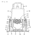
Fig. 1 is a partly broken away perspective view showing a state before a lower cover is mounted on the body of an electrical connection box according to an embodiment of the present invention. -
Fig. 2 is an exploded perspective view showing a female connector and a lower cover. -
Fig. 3 is a front view partly in section showing a state in which the female connector has been mounted on the lower cover. -
Fig. 4 is a side view partly in section showing a state before a connector connection part is connected to the female connector. -
Fig. 5 is a side view partly in section showing a state in which the female connector and the connector connection part are aligned with each other. -
Fig. 6 is a side view partly in section showing a state in which the female connector and the connector connection part are normally connected with each other. - An electrical connection box according to the invention is identified by the numeral 10 in
FIG.1 . The connector 10 has abody 11, a lower orlateral cover 20 mounted on a lower or lateral surface of thebody 11, and afemale connector 30 mounted on thelower cover 20 and connected to the lower surface of thebody 11. - As shown in
Fig. 1 , thebody 11 of the electrical connection box 10 is substantially a solid flat rectangle that is long and narrow in a right-to-left direction. Thebody 11 has an upper surface with a plurality of part-mounting portions for mounting electric parts, such as relays and fuses. Right and left or lateralconnector connection parts 13 are formed on the lower surface of thebody 11, and thefemale connector 30 can be fit on theconnector connection parts 13. Thebody 11 accommodates circuits composed of bus bars (not shown) layered one upon another. A portion of each bus bar at least partly projects into eachconnector connection part 13 and functions as a terminal (not shown). - As shown in
Fig. 1 , thelower cover 20 is an upwardly or laterally open box that is long and narrow in the right-to-left direction. Two lockingpieces 21 extend up from an upper end of each of a front wall and a rear wall of thelower cover 20. The lockingpieces 21 are configured to be locked elastically or resiliently with lockingclaws 14 formed respectively on front and rear surfaces of thebody 11. Thus, thelower cover 20 can be mounted on thebody 11, with thelower cover 20 at least partly substantially covering the lower surface of thebody 11. One ormore guide ribs 15 project down from the widthwise center of the front and rear surfaces of thebody 11, andpositioning grooves 25 are formed on the front and rear walls of thelower cover 20. Theguide ribs 15 can be at least partly inserted (preferably substantially vertically) into thecorresponding guide grooves 25. As shown inFigs. 2 and4 , right and left connector-holdingparts 22 are formed on the upper surface of thebottom wall 20A of thelower cover 20. Each connector-holdingpart 22 is a long narrow rectangle that opens up. A large cut out 23 is formed in the widthwise center of the rear wall of each connector-holdingpart 22. Thecutout 23 is formed to at least partly receive an electric wire W to be pulled out from thefemale connector 30 that will be described later. The electric wire W is led to the outside through an electric wire port (not shown) formed on the rear wall of thelower cover 20. One or two reinforcingportions 26 are formed integrally or unitarily on each outer surface of the connector-holdingpart 22 for preventing thelower cover 20 from deforming. Slip-off prevention projections 27 project (preferably substantially horizontally) inward from the inner periphery of the connector-holdingpart 22, and are formed at positions substantially aligned with the upper end of each reinforcingportion 26. Draw holes 28 are formed on thebottom wall 20A of theconnector holding part 22 immediately below the slip-off prevention projections 27. The entirelower cover 20, including the connector-holdingpart 22, can be preferably formed by molding a material in two dies (not shown) that open and close (preferably substantially vertically). The height of the peripheral wall of the connector-holdingpart 22 is set to substantially accommodate the entirefemale connector 30 held by the connector-holdingpart 22. - As shown in
Figs. 2 through 4 , thefemale connector 30 has afemale housing 31 substantially in the shape of a block that is long and narrow in a front-to-back direction. Thefemale connector 30 also has a substantially rectangular box-shapedholder 50 that at least partly accommodates thefemale housing 31, and anelectric wire cover 60 mounted on the lateral or lower part of theholder 50. -
Cavities 32 are formed in thefemale housing 31 in one or more, preferably a plurality of rows. A female terminal fitting (not shown) connected to a terminal of the electric wire W is at least partly inserted into eachcavity 32 preferably from below and at least partly accommodated therein. Thefemale housing 31 is fit slidably in theholder 50 and can be held at a forward position (seeFig. 4 ) at which most of thefemale housing 31 projects out from the upper edge of theholder 50 and a rearward position (seeFig. 6 ) at which thefemale housing 31 is accommodated in theholder 50. - As shown in
Fig. 4 , theconnector connection part 13 of thebody 11 of the electrical connection box 10 has the shape of a hood that opens down. Thefemale housing 31 of thefemale connector 30 can be at least partly fit or inserted in theconnector connection part 13, and theholder 50 can be at least partly fit or inserted on the periphery of theconnector connection part 13. As shown inFig. 1 , theconnector connection parts 13 have almost the same configuration and preferably are arranged substantially symmetrically in the right-to-left direction. Terminals (not shown) project into theconnector connection part 13 from positions on its bottom surface corresponding to thecavities 32 of thefemale connector 30. - One or
more levers 40 are mounted on the opposed side surfaces of thefemale housing 31, and acurved cam groove 41 is formed on a side of eachlever 40. Ashaft 42 supports thelever 40 rotatably or pivotably in such a way that the lateral (right and left) sides of thelever 40 are symmetrical with respect to a certain point. Aconnection pin 43 is disposed on the end of thelever 40 opposite thecam groove 41 and is fit on aconnection groove 51 of theholder 50 to connect thelever 40 and theholder 50 to each other. When thefemale housing 31 is held at the forward position, an entrance of thecam groove 41 of eachlever 40 is open e.g. substantially upward. Follower pins 16 extend from lateral (right and left) side surfaces of theconnector connection part 13 and can be at least partly fit or inserted in thecam grooves 41 of thelevers 40. - The right and left follower pins 16 are disposed at the entrance of the
cam groove 41 of the substantially correspondinglever 40 when theconnector connection part 13 is fit on thefemale housing 31 at the forward position. Theconnector connection part 13 can be pressed further into theholder 50 and presses thefemale housing 31 into theholder 50, while rotating thelever 40. Consequently theconnector connection part 13 is moved toward thefemale housing 31 by the action of levers between thecam groove 41 and thefollower pin 16. Thefemale connector 30 and theconnector connection part 13 fit normally on each other when the female housing is pressed to the rearward position. - The
electric wire cover 60 is an upwardly or laterally open box that can be accommodated inside the connector-holdingpart 22 with a space between theelectric wire cover 60 and the connector-holdingpart 22 in the front-to-back direction and/or the right-to-left direction. More specifically, theelectric wire cover 60 is slidable in a predetermined or predeterminalbel range in the front-to-back direction and/or the right-to-left direction, with the bottom surface of theelectric wire cover 60 in contact with thebottom wall 20A of the connector-holdingpart 22. One ormore locking pieces 61 extend up from the upper end of the periphery of theelectric wire cover 60 and can be locked to lockingprojections 52 formed at the lower end of theholder 50. Thus, theelectric wire cover 60 can be mounted on theholder 50 in such a way as to cover almost the entire lower surface of theholder 50. Anelectric wire outlet 62 is formed preferably substantially centrally on the rear surface of theelectric wire cover 60, and the electric wire W to be pulled out from the lower end of thefemale housing 31 is bent laterally (rearward) at the inner side of theelectric wire cover 60 and pulled out to the outside from theelectric wire outlet 62. One or more elastic orresilient pieces 63 are formed on each outer surface of theelectric wire cover 60 at locations aligned with the respective slip-off prevention projections 27 of theconnector holding part 22. Eachelastic piece 63 is cantilevered upward or laterally from a lower portion of each wall surface of theelectric wire cover 60 and is deformable toward the wall surface. A plate-shapedlocking projection 64 projects from the outer surface of the leading (upper) end of theelastic piece 63 in the entire width thereof and can be locked beneath the corresponding slip-off prevention projection 64. A taperedrib 65 is formed preferably at the substantially widthwise center of the underside of the lockingprojection 64 and projects gradually lesser distances from theelastic piece 63 as therib 65 extends toward the base side (lower side) of theelastic piece 63. - Initially the
female housing 31 of thefemale connector 30 is at least partly accommodated in theholder 50 at its forward position. Each lockingpiece 61 of theelectric wire cover 60 then is locked to the lockingprojection 52 of theholder 50 to hold theelectric wire cover 60 on the lower portion of theholder 50. At this time, the electric wire W extends or can extend from the lower end of thefemale housing 31 is pulled out to the outside through theelectric wire outlet 62 of theelectric wire cover 60. - The
holder 50 for thefemale connector 30 then is at least partly inserted from above into the connector-holdingpart 22 of thelower cover 20. As a result, eachelastic piece 63 is pressed down substantially into contact with the projected edge of the corresponding slip-off prevention projection 27, and theelastic pieces 63 deform elastically inward. Theelastic pieces 63 restore elastically or resiliently toward or to their original state when the bottom surface of the electric wire cover 60 contacts thebottom wall 20A of the connector-holdingpart 22. Consequently the lockingprojection 64 of theelastic piece 63 is locked to the surface of the slip-off prevention projection 27. Thefemale connector 30 is supported for elastic or resilient displacement along thebottom wall 20A of the connector-holdingpart 22, but is prevented from slipping off e.g. upward from the connector-holdingpart 22. The electric wire W is or can be led to the outside through thecutout 23 of thelower cover 20 and an electric wire port. - The tapered
rib 65 on the underside of each lockingprojection 64 slides on the projected edge of the slip-off prevention projection 27 in a direction from the lower side thereof to the higher side thereof. Thus theelastic piece 63 undergoes a smooth elastic or resilient deformation. More specifically, therib 65 functions as the guide for elastically deforming theelastic piece 63 and as the means for reinforcing the lockingprojection 64. As described above, the connector-holdingpart 22 holds thefemale connector 30 below the upper end of the periphery of thelower cover 20 and thus thefemale connector 30 preferably does not project out from thelower cover 20. - The
lower cover 20 supports a pair of thefemale connectors 30 in a wait state, as shown with the arrow ofFig. 1 , so that thebody 11 of the electrical connection box 10 is mounted on thelower cover 20 from above. Initially, as shown inFig. 4 , the leading end of eachguide rib 15 is inserted into thepositioning groove 25 to place thebody 11 and thelower cover 20 in position. At this time, thefemale connector 30 and theconnector connection part 13 are spaced from each other. - The
body 11 is moved toward thelower cover 20 in this state, and theguide rib 15 is at least partly inserted deep into thepositioning groove 25. In this manner, thebody 11 and thelower cover 20 are placed substantially horizontally placed in position and approach each other in a tilting-prevented state. There is a possibility that the lower end of theconnector connection part 13 will not align properly with thefemale connector 30 as they move in contact with each other. For example, as shown inFig. 4 , let it be supposed that the axis X of theconnector connection part 13 is dislocated rearward (left-hand side inFig. 4 ) from the axis Y of thefemale connector 30. When the leading end of theconnector connection part 13 and that of thefemale housing 31 are butted against each other, the rearelastic piece 63 deforms elastically or resiliently and thefemale connector 30 shifts rearward slidably on thebottom wall 20A, as shown inFig. 5 . In this manner, theconnector connection part 13 and thefemale connector 30 are aligned with each other. - The
connector connection part 13 is pressed further into theholder 50 so that the lateral (right and left) follower pins 16 are disposed at the entrance of thecam grooves 41 of the correspondinglevers 40. Thefemale housing 31 then is pressed into theholder 50 so that thelever 40 is rotated. As a result, theconnector connection part 13 is moved toward thefemale housing 31 by the action of levers between thecam grooves 41 and the follower pins 16. In this manner, thefemale connector 30 and theconnector connection part 13 fit normally on each other (seeFig. 6 ). Theconnector connection parts 13 preferably are arranged substantially symmetrically in the right-to-left direction (longitudinal direction of the body 11). Therefore, a force can be applied uniformly to bothconnector connection parts 13. - On the other hand, the axis X of the
connector connection part 13 may be dislocated forward from the axis Y of thefemale connector 30. In this case,, the frontelastic piece 63 deforms elastically and thefemale connector 30 shifts forward slidably to align theconnector connection part 13 and thefemale connector 30 with each other. The axis X of theconnector connection part 13 and the axis Y of thefemale connector 30 could be dislocated from each other in the right-to-left direction. In this case, the left-handelastic piece 63 or the right-handelastic piece 63 deforms elastically and thefemale connector 30 shifts slidably in the right-to-left direction to align theconnector connection part 13 and thefemale connector 30 with each other. - As described above, the
female connector 30 is mounted initially in the wait or stand-by state. As a result, the mounting of thelower cover 20 on thebody 11 connects thefemale connector 30 to theconnector connection part 13 of thebody 11. Thus, thelower cover 20 can be mounted on thebody 11 with a high efficiency. - Both the
body 11 and thelower cover 20 are large molded products, and it is difficult to obtain a high precision in mounting thelower cover 20 on thebody 11. Thus, there is a possibility that thefemale connector 30 and theconnector connection part 13 could be misaligned from each other. But, according to the embodiment, the elastic orresilient piece 63 supports thefemale connector 30 for elastic or resilient displacement. Thus, thefemale connector 30 shifts to correct any misalignment between thefemale connector 30 and theconnector connection part 13. Therefore thelower cover 20 can be mounted on thebody 11 easily. - The
electric wire cover 60 with theelastic piece 63 is provided at the lower or lateral portion of thefemale housing 31 and slidably contacts thebottom wall 20A of thelower cover 20. Thefemale connector 30 in the wait state and theconnector connection part 13 may be dislocated from each other while mounting thelower cover 20 on thebody 11 of the electrical connection box. However, thefemale connector 30 shifts elastically or resiliently along thebottom wall 20A of thelower cover 20, thus absorbing the dislocation. Therefore thelower cover 20 can be mounted on thebody 11 easily. - Known panel-mounted connector have self-aligning mechanisms for absorbing a dislocation between connectors. The panel-mounted type connector is supported, with the connector penetrating through a mounting hole formed on a panel and displaceable vertically and horizontally through an elastic piece. When the connector fits on a mating connector, the elastic piece deforms and absorbs the dislocation between the connectors.
- However, if the supporting construction of the panel-mounted connector is used for the connector of the electrical connection box, the connector would be supported elastically with the connector penetrating through an opening formed on a bottom wall of a lower cover. In this case, water that has leaked up from a portion below the electrical connection box splashes on the connector or penetrates into the lower cover from the opening of the bottom wall, which is undesirable.
- On the other hand, according to the invention, it is unnecessary to form a through-hole on the
bottom wall 20A of thelower cover 20. Thus, it is possible to prevent water from splashing on thefemale connector 30. - Connection between the
female connector 30 and theconnector connection part 13 starts after thebody 11 of the electrical connection box and thelower cover 20 are placed in position by the guide means (preferably theguide rib 15 and the positioning groove 25). Therefore the connection between thefemale connector 30 and theconnector connection part 13 can be accomplished reliably. - The
female connector 30 does not project outside from thelower cover 20 when thefemale connector 30 is mounted on theconnector holding part 22 of thelower cover 20. Thus thefemale connector 30 can be protected. - Moreover plural
connector connection parts 13 are disposed substantially symmetrically on the lower or lateral surface of thebody 11 of the electrical connection box. Therefore, it is possible to apply a uniform force to bothconnector connection parts 13 during mounting and to prevent thebody 11 from inclining longitudinally. - The technical scope of the present invention is not limited to the above-described embodiment, but the modes which are described below is included in the technical scope of the present invention as defined by the claims.
- The present invention is applicable to the case in which a male connector is mounted on the lower cover.
- According to the present invention, it is possible to provide a desired number of wait-side connectors and to provide some of the wait-side connectors or all of them with the self-aligning mechanism of the present invention.
- Preferably, an
electric wire cover 60 is mounted on a lower portion of ahousing 31 of afemale connector 30. Theelectric wire cover 60 is accommodated inside a rectangular box-shaped connector-holdingpart 22 formed on abottom wall 20A of alower cover 20, and anelastic piece 63 is interposed between thefemale connector 30 and the connector-holdingpart 22. Thus, thefemale connector 30 is supported for elastic displacement in a wait state. In consequence of mounting of thelower cover 20 on thebody 11, thefemale connector 30 is connected to aconnector connection part 13 of thebody 11 of an electrical connection box. Thus in the case where there is a dislocation between thefemale connector 30 and theconnector connection part 13, thefemale connector 30 shifts along thebottom wall 20A of thelower cover 20, thus absorbing the dislocation.
Claims (10)
- An electrical connection box comprising:a body (11) having upper and lower surfaces, a connector connection part (13) formed on the lower surface;a connector (30) to be provided at an end of an electric wire and connectable to said connector connection part (13);a lower cover (20) mounted on said body (11) and covering the lower surface of said body (11), said lower cover (20) having a connector-holding part (22) capable of holding said connector (30) and a bottom wall (20A);characterized byan elastic member (63) interposed between said connector (30) and said connector-holding part (22) to support said connector (30) for elastic displacement along said bottom wall (20A) of said cover (20), wherein said connector (30) is placed in a wait state with said connector-holding part (22) holding said connector (30) and in consequence of mounting of said lower cover (20) on said body (11), said connector (30) is connected to said connector connection part (13).
- The electrical connection box of claim 1, wherein an electric wire cover (60) for laterally pulling out said electric wire is mounted on a lower portion of a housing (31) of said connector (30); and a bottom surface of said electric wire cover (60) is allowed to slide on a bottom wall (20A) of said lower cover (20), and said elastic member (63) interposed between said electric wire cover (60) and said connector-holding part (22) is formed on a periphery of said electric wire cover (60) so that said connector (30) is supported for elastic displacement along said bottom wall (20A) of said lower cover (20).
- The electrical connection box of one or more of the preceding claims, wherein a guide means for guiding an operation of mounting said lower cover (20) on said body (11) is provided on said lower cover (20) and said body (11), and in mounting said lower cover (20) on said body (11), a connection between said connector (30) and said connector connection part (13) starts after said body (11) and said lower cover (20) are placed in position by said guide means.
- The electrical connection box of one or more of the preceding claims, wherein a height of a peripheral wall of said lower cover (20) is set to accommodate an entire connector (30) mounted on said connector-holding part (22).
- The electrical connection box of one or more of the preceding claims, wherein on said lower surface of said body (11), a plurality of said connector connection parts (13) are symmetrically disposed in a longitudinal direction of said body (11).
- An electrical connection box of one or more of the preceding claims, further comprising:a holder (50) having a top opening for slideably receiving the connector (30) in a forward position where the connector (30) projects from the holder (50) and in rearward position where the connector (30) is within the holder (50), anda wire cover (60) for engaging the holder (50) and for guiding the wire (W) from the connector (30)..
- The electrical connection box of one or more of the preceding claims, wherein the elastic member (63) comprises elastic pieces (63) formed unitarily with the wire cover (60).
- The electrical connection box of one or more of the preceding claims, further comprising guide ribs (65) formed on the elastic pieces (63) for guiding the connector assembly into the connector-holding part (22) of the lower cover (20).
- The electrical connection box of one or more of the preceding claims, wherein the wire cover (60) has a substantially solid bottom wall for enclosing said wire (W) and said connector (30).
- The electrical connection box of one or more of the preceding claims, wherein said connector-holding part (22) has a continuous side wall extending up from said bottom wall (20A) of the lower cover (20), the bottom wall of the wire cover (60) slideably disposed on the bottom wall (20A) of the lower cover (20).
Priority Applications (2)
| Application Number | Priority Date | Filing Date | Title |
|---|---|---|---|
| EP20030016524 EP1501158B1 (en) | 2003-07-22 | 2003-07-22 | Electrical connection box |
| DE60324268T DE60324268D1 (en) | 2003-07-22 | 2003-07-22 | Electrical connection housing |
Applications Claiming Priority (1)
| Application Number | Priority Date | Filing Date | Title |
|---|---|---|---|
| EP20030016524 EP1501158B1 (en) | 2003-07-22 | 2003-07-22 | Electrical connection box |
Publications (2)
| Publication Number | Publication Date |
|---|---|
| EP1501158A1 EP1501158A1 (en) | 2005-01-26 |
| EP1501158B1 true EP1501158B1 (en) | 2008-10-22 |
Family
ID=33483920
Family Applications (1)
| Application Number | Title | Priority Date | Filing Date |
|---|---|---|---|
| EP20030016524 Expired - Lifetime EP1501158B1 (en) | 2003-07-22 | 2003-07-22 | Electrical connection box |
Country Status (2)
| Country | Link |
|---|---|
| EP (1) | EP1501158B1 (en) |
| DE (1) | DE60324268D1 (en) |
Cited By (1)
| Publication number | Priority date | Publication date | Assignee | Title |
|---|---|---|---|---|
| US10424885B2 (en) | 2012-11-06 | 2019-09-24 | Server Technology, Inc. | High outlet density power distribution unit |
Families Citing this family (4)
| Publication number | Priority date | Publication date | Assignee | Title |
|---|---|---|---|---|
| WO2007115584A1 (en) * | 2006-04-11 | 2007-10-18 | Fci | Electrical connector capable of absorbing manufacturing tolerances |
| US11296467B2 (en) | 2012-11-06 | 2022-04-05 | Server Technology, Inc. | High outlet density power distribution unit |
| DE102016107412A1 (en) * | 2016-04-21 | 2017-10-26 | Phoenix Contact Gmbh & Co. Kg | Connector part with modular contact inserts inserted into a holding frame |
| JP6840517B2 (en) * | 2016-11-18 | 2021-03-10 | 日本航空電子工業株式会社 | Connector and composite connector |
Family Cites Families (5)
| Publication number | Priority date | Publication date | Assignee | Title |
|---|---|---|---|---|
| JP3000131B2 (en) * | 1994-09-14 | 2000-01-17 | 矢崎総業株式会社 | Wire holding mechanism |
| KR20010022868A (en) * | 1997-08-14 | 2001-03-26 | 홀리 엘리자베스 리즈 | Self docking instrument panel connector system |
| US6095852A (en) * | 1998-12-17 | 2000-08-01 | Yazaki North America, Inc. | Connector bracket wire shield with connector retention arms |
| JP4122101B2 (en) * | 1998-12-21 | 2008-07-23 | 矢崎総業株式会社 | Split connector |
| EP1104048A3 (en) * | 1999-10-28 | 2003-12-17 | Tyco Electronics Corporation | Blind mate electrical connector with mechanical assist means |
-
2003
- 2003-07-22 DE DE60324268T patent/DE60324268D1/en not_active Expired - Lifetime
- 2003-07-22 EP EP20030016524 patent/EP1501158B1/en not_active Expired - Lifetime
Cited By (2)
| Publication number | Priority date | Publication date | Assignee | Title |
|---|---|---|---|---|
| US10424885B2 (en) | 2012-11-06 | 2019-09-24 | Server Technology, Inc. | High outlet density power distribution unit |
| US10424884B2 (en) | 2012-11-06 | 2019-09-24 | Server Technology, Inc. | High outlet density power distribution unit |
Also Published As
| Publication number | Publication date |
|---|---|
| DE60324268D1 (en) | 2008-12-04 |
| EP1501158A1 (en) | 2005-01-26 |
Similar Documents
| Publication | Publication Date | Title |
|---|---|---|
| US6926545B2 (en) | Electrical connection box with a lower cover for holding and mounting a connector | |
| US5252096A (en) | Connector | |
| EP1313176B1 (en) | Electric connector and socket connector | |
| US6659797B2 (en) | Connector with resiliently deflectable lock arm | |
| US8579655B2 (en) | Device connector | |
| EP1562262B1 (en) | A connector and a method of mounting it to an electric device | |
| US7044808B1 (en) | Connector assembly with terminal position assurance device | |
| US11005215B2 (en) | Connector and connector assembly | |
| EP1501158B1 (en) | Electrical connection box | |
| JPH0717192Y2 (en) | Packaging equipment | |
| US10128605B2 (en) | Connector | |
| JP3960259B2 (en) | Connector connection structure | |
| JP3467419B2 (en) | Connector lock structure | |
| JPH0955238A (en) | Terminal device | |
| CN113711443A (en) | Joint connector | |
| JP2009170323A (en) | Connector | |
| JP2004178823A (en) | Receptacle connector with latch arm and plug connector connected thereto | |
| EP2230730B1 (en) | Cable connector | |
| GB2282277A (en) | Memory card connector and card eject unit | |
| JP3788571B2 (en) | connector | |
| JP4911712B2 (en) | Electrical connector assembly | |
| JP2011049030A (en) | Socket for relay | |
| EP1569305B1 (en) | Electrical plug connector | |
| JP2017054590A (en) | Card edge connector | |
| CN120826843A (en) | Connectors |
Legal Events
| Date | Code | Title | Description |
|---|---|---|---|
| PUAI | Public reference made under article 153(3) epc to a published international application that has entered the european phase |
Free format text: ORIGINAL CODE: 0009012 |
|
| 17P | Request for examination filed |
Effective date: 20030814 |
|
| AK | Designated contracting states |
Kind code of ref document: A1 Designated state(s): AT BE BG CH CY CZ DE DK EE ES FI FR GB GR HU IE IT LI LU MC NL PT RO SE SI SK TR |
|
| AX | Request for extension of the european patent |
Extension state: AL LT LV MK |
|
| 17Q | First examination report despatched |
Effective date: 20050606 |
|
| AKX | Designation fees paid |
Designated state(s): DE FR IT |
|
| GRAP | Despatch of communication of intention to grant a patent |
Free format text: ORIGINAL CODE: EPIDOSNIGR1 |
|
| GRAS | Grant fee paid |
Free format text: ORIGINAL CODE: EPIDOSNIGR3 |
|
| GRAA | (expected) grant |
Free format text: ORIGINAL CODE: 0009210 |
|
| AK | Designated contracting states |
Kind code of ref document: B1 Designated state(s): DE FR IT |
|
| REF | Corresponds to: |
Ref document number: 60324268 Country of ref document: DE Date of ref document: 20081204 Kind code of ref document: P |
|
| PLBE | No opposition filed within time limit |
Free format text: ORIGINAL CODE: 0009261 |
|
| STAA | Information on the status of an ep patent application or granted ep patent |
Free format text: STATUS: NO OPPOSITION FILED WITHIN TIME LIMIT |
|
| 26N | No opposition filed |
Effective date: 20090723 |
|
| PGFP | Annual fee paid to national office [announced via postgrant information from national office to epo] |
Ref country code: IT Payment date: 20140606 Year of fee payment: 12 |
|
| PGFP | Annual fee paid to national office [announced via postgrant information from national office to epo] |
Ref country code: DE Payment date: 20140716 Year of fee payment: 12 |
|
| PGFP | Annual fee paid to national office [announced via postgrant information from national office to epo] |
Ref country code: FR Payment date: 20140708 Year of fee payment: 12 |
|
| REG | Reference to a national code |
Ref country code: DE Ref legal event code: R119 Ref document number: 60324268 Country of ref document: DE |
|
| PG25 | Lapsed in a contracting state [announced via postgrant information from national office to epo] |
Ref country code: IT Free format text: LAPSE BECAUSE OF NON-PAYMENT OF DUE FEES Effective date: 20150722 Ref country code: DE Free format text: LAPSE BECAUSE OF NON-PAYMENT OF DUE FEES Effective date: 20160202 |
|
| REG | Reference to a national code |
Ref country code: FR Ref legal event code: ST Effective date: 20160331 |
|
| PG25 | Lapsed in a contracting state [announced via postgrant information from national office to epo] |
Ref country code: FR Free format text: LAPSE BECAUSE OF NON-PAYMENT OF DUE FEES Effective date: 20150731 |