BACKGROUND OF THE INVENTION
1. FIELD OF THE INVENTION
The present invention relates to a vehicular radar
device installed on, for example, a vehicle and operative to
detect the presence or absence of a preceding vehicle or the
like and position information on the same by using
electromagnetic waves such as laser light.
2. DESCRIPTION OF THE RELATED ART
Wide advances have heretofore made in the development
of radars to be used in vehicles for purposes such as
monitoring of forward obstacles and adaptive cruise control
(vehicular radar devices), and a radio wave system and a laser
system are known. Each of these systems is constructed to
transmit an electromagnetic wave such as a radio wave or laser
light toward an object within a predetermined detection area,
and finds the distance to the target from a reception delay
time which elapses until the radar receives a reflected wave
of the electromagnetic wave. There is also another system
which detects the direction and the like of a target by
transmitting an electromagnetic wave while scanning it.
In such a vehicular radar device, as a matter of course,
rain, snow, fog and the like as well as a road surface need
to be detected in the state of being discriminated from a
vehicle and the like, so that their measured data are
eliminated from monitoring targets to prevent rain, snow, fog
and the like as well as a road surface from being erroneously
detected as a monitoring target (such as an objective vehicle
or an obstacle).
In addition, since this kind of vehicular radar device
(a laser radar in particular), when it is influenced by rain,
snow, fog or the like, suffers a lowering in detection
distance performance, rain or the like needs to be detected
in the state of being discriminated from a vehicle or the like
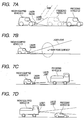
which is a monitoring target. As shown in Fig. 7A by way of
example, when the detection distance performance of a radar
device provided in a vehicle C1 is lowered by unfavorable
weather such as rain, the radar device will not be able to
detect a preceding vehicle C2, until the distance of the
preceding vehicle C2 from the vehicle C1 approaches a position
which lies at a shorter distance as shown by symbol C3.
Accordingly, in this situation, it is desirable to take
measures such as the processing of making the transmission
power and the reception sensitivity of the radar device higher
than those under normal conditions so as to maintain the
distance performance at approximately the same level as that
under normal conditions, or the processing of outputting a
warning informing a driver that the distance performance has
lowered.
Fig. 8B shows data obtained by actually measuring a
received light waveform in the case where a predetermined
target is installed at a short distance (20 m) under
unfavorable weather conditions entailing a rainfall of 30 mm
per hour (in Fig. 8A, the horizontal and vertical axes
represent distance (m) and received light quantity,
respectively). Fig. 8C shows data obtained by similarly
actually measuring a received light waveform in the case where
a predetermined target is installed at a long distance (40
m) under similar unfavorable weather conditions. It can be
seen from Figs. 8B and 8C that under the unfavorable weather
conditions, the waveform of the target installed at the short
distance exceeds the threshold of the received light quantity
and can be detected, whereas the waveform of the target
installed at the long distance does not exceed the threshold
of the received light quantity and cannot be detected, so that
the detection distance performance becomes low under the
unfavorable weather conditions. The threshold is preset on
the basis of experiments and the like so that erroneous
detection due to noise can be eliminated.
To meet this demand, Patent Document 1 (Japanese Patent
No. 2,776,253) proposes a laser radar which makes a decision
as to reflected light from fog or the like on the basis of
a received waveform.
Patent Document 2 (JP-A-2000-65932) proposes a
vehicular optical radar device which determines that a
detection target is snow or fog, when it is recognized that
the distance of the detection target is approximately the same
over a predetermined range of scanning angles (or it is
recognized that the relative speed of the detection target
is zero).
Patent Document 3 (JP-A-9-159765) proposes a vehicular
radar device which sets reference data on the basis of
measured data determined to contain no reflected light from
an object and corrects measured data on the basis of this
reference data, thereby extracting only reflected light of
the object from measured data including scattered light due
to snow or waterdrops.
Patent Document 4 (JP-A-2000-40139) proposes a method
of recognizing an object ahead of a vehicle, which prevents
a non-monitoring target such as splashes from being detected,
as by relatively lowering the output level of and reception
sensitivity to a transmitted wave in a region where there is
a low possibility that a monitoring target such as a vehicle
may exist.
Patent Document 5 (JP-A-2003-42757) proposes a
vehicular distance measuring device which determines whether
a detection target is a road surface, on the basis of a
detected distance and a received waveform (a feature quantity
of reflected light).
SUMMARY OF THE INVENTION
However, the above-mentioned related arts have the
problem that a road surface which does not greatly influence
the detection distance performance cannot be discriminated
from rain or the like, so that it is difficult to make a correct
decision as to the state in which the detection distance
performance is deteriorated by rain or the like.
As shown in Fig. 78 by way of example, if road surface
reflection occurs due to the mounting position or angle of
a radar or due to the undulations or shape of a road surface,
the road surface is erroneously determined as rain or the like
and the radar erroneously determines that the detection
distance performance is deteriorated, so that there is a risk
that the radar itself causes problems such as erroneous
outputting of the above-mentioned warning.
In addition, there is a risk that, owing to a distance
range in which a monitoring target such as a vehicle exists,
or because of the shape, reflectance and the like of the
vehicle or the like, the radar erroneously determines the
vehicle or the like as the road surface and eliminates the
vehicle or the like from monitoring targets. For example,
the device of Patent Document 5 determines whether the
detection target is a road surface, on the basis of the
detection distance and the received waveform (the feature
quantity of reflected light), so that if a vehicle having a
shape and a reflectance which produce a received waveform
showing the above-mentioned feature quantity exists in a
predetermined area, this vehicle is erroneously determined
as a road surface and is erroneously eliminated from
monitoring targets.
As shown in Figs. 7C and 7D by way of example, in the
case where there is a difference between the radar
installation height of the vehicle C1 (C5) and the height of
a preceding vehicle C4 (C6), if the distance between the
vehicle C1 (C5) and the preceding vehicle C4 (C6) becomes
extremely short, laser light fails to illuminate the
preceding vehicle C4 (C6) to a sufficient extent, and the
light waveform received from the preceding vehicle C4 (C6)
assumes a received light waveform (with a small received light
quantity and a comparatively wide range of distribution)
which is similar to the light waveform shown in Fig. 8A, which
is received from the road surface or the like as will be
described later. For this reason, even with the method of
making a decision as to a detection target on the basis of
a received light waveform (including a detection distance),
it is impossible to positively discriminate between a road
surface and a vehicle during detection.
Fig. 8A shows data examples of received light waveforms
of a road surface and rain or the like as well as a vehicle
(preceding vehicle). As shown, since the received light
waveform of the vehicle is only distributed in a particular
range with a comparatively large received light quantity, the
vehicle and rain or the like which tends to be distributed
over a wide range with a small received light quantity can
be discriminated from each other to a certain extent owing
to the difference between their received light waveforms
(including the difference between their detection distances).
However, the received light waveforms of the road surface and
rain or the like have remarkably similar features, so that
it is extremely difficult to discriminate between the road
surface and rain or the like on the basis of the difference
between the received light waveforms. In addition, as
described above, there is a case where the light quantity
received from the vehicle, owing to the shape or reflectance
thereof, becomes small and the received light waveforms of
the road surface and the vehicle become remarkably similar
to each other. Accordingly, it is also difficult to
positively discriminate between the road surface and the
vehicle on the basis of the difference between the received
light waveforms.
The invention, therefore, provides a vehicular radar
device capable of detecting rain or the like or a road surface
by discriminating the rain or the like or the road surface
and others.
A first vehicular radar device according to the
invention is a vehicular radar device which detects an object
such as an objective vehicle within a detection area on the
basis of detection data having a reception intensity
exceeding a predefined threshold, the detection data being
contained in reflected-wave data on waves irradiated into the
detection area outward of a vehicle provided with the
vehicular radar device. The vehicular radar device includes
control processing means capable of varying a direction
or/and a range of the detection area in a vertical direction,
and the control processing means is operative to set, during
a normal time, the direction or/and the range of the detection
area in the vertical direction to a normal state in which the
objective vehicle is correctly detected, and perform a
detection operation in the normal state, and is operative to
perform, during a rain decision time for making a decision
as to rain or the like, a detection operation in an up state
in which the direction or/and the range of the detection area
is shifted comparatively upwardly in the vertical direction
so that at least a road surface is not detected, and determine
that, from among detection data obtained during the up state,
detection data which does not vary in reception intensity nor
in reception delay time for a predefined time is detection
data relative to rain or the like.
A second vehicular radar device according to the
invention is a vehicular radar device similar to the first
vehicular radar device and including control processing means
capable of varying a direction or/and a range of the detection
area in a vertical direction. The control processing means
is operative to set, during a normal time, the direction
or/and the range of the detection area in the vertical
direction to a normal state in which the objective vehicle
is correctly detected, and perform a detection operation in
the normal state, and is operative to perform, during a
road-surface decision time for making a decision as to a road
surface, a detection operation in a down state in which the
direction or/and the range of the detection area is shifted
comparatively downwardly in the vertical direction so that
the road surface is correctly detected, and determine that,
from among detection data obtained during the down state,
detection data which varies in reception delay time compared
to a detection operation in an immediately previous normal
state is detection data relative to the road surface.
The term "rain or the like" signifies objects other than
a monitoring target and a road surface, which are detected
under unfavorable weather or the like, and includes at least
rain, snow, fog, hailstones, dust and the like.
The term "direction of detection area" signifies the
direction of the central axis of the detection area (the
visual field of the radar), and in the case of a general laser
radar having a detection area spreading in a fan-shaped form,
the term signifies the direction of a so-called optical axis.
The term "range of detection area" signifies the width size
of the detection area which spreads from its central axis on
the opposite sides thereof, and in the case of a general laser
radar, the term signifies an angular range centered at the
optical axis. The term "vertical direction" signifies a
direction which is vertical to a road surface on which a
vehicle runs. The term "normal time" signifies a time which
is not the rain decision time nor the road surface decision
time. The term "normal state in which objective vehicle is
correctly detected" generally signifies the state in which
the central axis of the detection area is approximately
parallel to (i.e., approximately horizontal with respect to)
the road surface, and the range of a predetermined angle
spreading vertically in the opposite directions from that
central axis constitutes the detection area spreading in the
vertical direction. The term "reception delay time"
signifies the distance data to a target which is measured by
the radar.
According to the first vehicular radar device of the
invention, the control processing means, during the rain
decision time, shifts the visual field of the radar into the
up state and makes a decision as to rain or the like. Namely,
from among detection data obtained during the up state,
detection data which satisfies the condition that the
reception intensity and the reception delay time (distance
data) do not vary for a predefined time is determined as
detection data relative to rain or the like. Accordingly,
it is possible to highly reliably discriminate between rain
or the like and others (including a road surface, an objective
vehicle and the like), and it is possible to highly
appropriately execute processing based on this
discrimination (for example, the processing of issuing a
warning to a user).
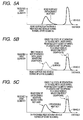
The reason for this is as follows. When the visual field
of the radar is shifted to the up state (the state in which
at least the road surface is out of the visual field), data
components relative to at least the road surface do not appear
as detection data, as shown in Fig. 5B by way of example. At
this time, as the result of the shift of the visual field,
data components relative to an objective vehicle or the like
decrease in reception intensity or do not appear as detection
data, as shown in Fig. 5B by way of example. In addition,
even if there remains a data component relative to the
objective vehicle or the like, this data is eliminated in the
decision based on the above-mentioned condition, because as
observation is performed for a given time period, the received
light quantity and the distance data necessarily vary with
the running of the vehicle. However, data relative to
unfavorable weather such as rain, even if it is observed for
the given time period, is observed at approximately the same
distance with an approximately constant received light
quantity (i.e., with approximately the same waveform) as
shown in Fig. 5C by way of example. Accordingly, through the
above-described decision, only the detection data relative
to rain or the like can be positively recognized in the state
of being discriminated from the road surface and the objective
vehicle or the like.
Incidentally, if the up state is the state in which the
direction or/and the range of the detection area is shifted
upwardly in the vertical direction so that the road surface
and the objective vehicle are not detected, the objective
vehicle or the like as well as the road surface positively
is not detected, and the condition "detection data whose do
not vary in reception intensity nor in reception delay time
for a predefined time" is not necessarily necessary.
Accordingly, it is also possible to adopt a construction which
unconditionally determines detection data obtained during
the up state, as detection data relative to rain or the like,
or a construction which makes a decision based on only a
decision using the feature quantity of a received waveform.
According to the second vehicular radar device of the
invention, the control processing means, during the road
surface decision time, shifts the visual field of the radar
into the down state and makes a decision as to the road surface.
Namely, from among detection data obtained during the down
state, detection data which satisfies the condition that the
reception delay time (distance data) varies compared to a
detection operation in an immediately previous normal state
is determined as detection data relative to the road surface.
Accordingly, it is possible to highly reliably
discriminate between the road surface and others (including
rain or the like and an objective vehicle or the like), and
it is possible to highly appropriately execute processing
based on this discrimination (for example, the processing of
issuing a warning to a user, the processing of eliminating
data relative to the road surface).
The reason for this is as follows. During the down state
(the state in which the road surface is detected as a closer
object) , as the result of the shift of the visual field, data
components relative to the road surface increase in reception
intensity and the distance data necessarily varies to
indicate a closer distance, as shown in Fig. 6B by way of
example. However, as shown in Fig. 6C by way of example, the
data relative to the objective vehicle or the like or rain
or the like may slightly decrease in reception intensity, but
is observed at approximately the same distance. Accordingly,
through the decision based on the above-mentioned condition,
only the detection data relative to the road surface can be
positively recognized in the state of being discriminated
from rain, the objective vehicle and the like.
It is to be noted that, during the above-mentioned
road-surface decision, only detection data which, as the
result of the shift to the down state, varies in the direction
in which the reception delay time becomes shorter (the
distance becomes shorter) may be determined as detection data
relative to the road surface. In this case, if there is
detection data which varies in the direction in which the
reception delay time becomes longer (data relative to an
object other than the road surface, for example, data relative
to noise), this detection data is eliminated, whereby it is
possible to make a decision as to data relative to the road
surface with far higher reliability.
In addition, during the above-mentioned road-surface
decision, only detection data whose reception delay time is
within a predefined range (detection data which is within a
predefined distance range) may also be determined as
detection data relative to the road surface. In this case
as well, since the road surface is detected in only a given
range near the vehicle on which the radar is installed,
compared to the objective vehicle or the like, it is possible
to make a decision as to data relative to the road surface
with far higher reliability.
A preferred embodiment of the invention provides a
construction in which when the control processing means is
to make a decision as to detection data relative to rain or
the like or the road surface during the above-described up
state or down state, a target decision based on the feature
quantity of a received waveform is first performed (a decision
based on a comparison between the feature quantity and a
previously registered reference value), and only when it is
determined that there exists detection data presumed to be
relative to rain or the like or the road surface, the
above-mentioned decision (the decision based on the
above-mentioned condition) is made.
This embodiment provides the advantage that, through a
comparatively simple target decision, after it has been
confirmed whether the above-mentioned decision is necessary,
the decision can be performed only when necessary, so that
useless decision processing can be avoided.
Another preferred embodiment of the invention provides
a construction in which when the control processing means is
to make a decision as to detection data relative to rain or
the like or the road surface during the above-described up
state or down state, a target decision based on the feature
quantity of a received waveform is first performed, and
detection data which is positively not relative to rain or
the like or the road surface is eliminated from decision
targets, whereby the decision processing can be made simple.
In addition, the above-mentioned rain decision time or
road surface decision time may be a time immediately after
a predefined interval time elapses (namely, it is also
possible to adopt a construction which periodically executes
the operation of shifting the visual field into the up state
to make a decision as to rain or the like or the operation
of shifting the visual field into the down state to make a
decision as to the road surface). Preferably, the following
construction is adopted.
Namely, it is possible to adopt a construction in which
the rain decision time or the road surface decision time is
a time at which when a target decision based on a feature
quantity of a received waveform is performed on the detection
data obtained through the detection operation in the normal
state, the result of the target decision shows that there
exists detection data presumed to be relative to the road
surface or rain or the like. In this case, there is the
advantage that a decision based on a shift of the visual field
is made only when necessary and a decision as to the road
surface or rain or the like is efficiently executed, whereby
it is possible to prevent power consumption or the like due
to useless operations (such as an unnecessary shift of the
visual field).
According to the vehicular radar device of the invention,
it is possible to highly reliably make a decision as to rain
or the like or a road surface by discriminating between rain
or the like on the road surface and others (including an
objective vehicle and the like), whereby it is possible to
highly appropriately execute processing based on this
decision (for example, the processing of issuing a warning
to a user, or the processing of eliminating 'data relative to
the road surface).
BRIEF DESCRIPTION OF THE DRAWINGS
The invention will become more readily appreciated and
understood from the following detailed description of a
preferred embodiment of the invention when taken in
conjunction with the accompanying drawings, in which:
DETAILED DESCRIPTION OF THE INVENTION
A preferred embodiment of the invention will be
described below with reference to the accompanying drawings.
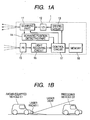
Figs. 1A and 1B are views aiding in describing a
vehicular radar device according to the preferred embodiment
of the invention. Fig. 1A is a view showing the construction
of the device, while Fig. 1B is a view showing an example in
which the vehicular radar device is installed on a vehicle.
In Fig. 1A, the vehicular radar device (in this
embodiment, a pulse-echo type of laser radar) is denoted by
reference numeral 1. This vehicular radar device 1 has a
scanning part 11, an LD (laser diode) 12, a driving circuit
13, a scanning position detecting part 14, a PD (photodiode)
15, a light receiving circuit 16, a control circuit 17, and
a memory 18.
The control circuit 17 corresponds to control
processing means in the invention. The scanning device 11,
the LD 12 and the driving circuit 13 constitute transmitting
means of the vehicular radar device 1, and the PD 15 and the
light receiving circuit 16 constitute receiving means of the
vehicular radar device 1. The scanning device 11, the LD 12
and their associated optical system (not shown) correspond
to a transmitting head of the vehicular radar device 1, while
the PD 15 and its associated optical system (not shown)
correspond to a receiving head of the vehicular radar device
1.
The scanning device 11 is operative to transmit laser
light outputted from the LD 12, while scanning the laser light
within a predetermined angular range (scanning area) at least
in the horizontal direction by means of a reflecting mirror
or the like which is swingably driven, and operates with
predetermined timing at a predetermined period under the
control of the control circuit 17. The scanning speed may
be a constant speed. The scanning area is generally set to
be slightly wider than a detection area in which measurement
is to be performed.
The driving circuit 13 is a circuit which is controlled
by the control circuit 17 and causes the LD 12 to operate to
output laser light (laser pulses) at emission timing
intervals generated by the control circuit 17. This emission
timing is preset, to obtain the predetermined resolution, so
that emission and reception of laser light is performed at
least once in each of detection regions formed by dividing
the scanning area by a predetermined width in the scanning
direction. The emission period of laser light may be
constant.
The scanning position detecting device 14 is an element
which detects the scanning direction of the scanning device
11 and inputs the resultant signal (scanning direction
signal) to the control circuit 17.
The PD 15 is operative to receive reflected light which
returns from a target when the transmitted laser light is
reflected therefrom, and outputs an electrical signal
corresponding to a received light quantity (received light
intensity) (the electrical signal is hereinafter referred to
as the received light quantity' signal). The received light
quantity signal outputted from the PD 15 is inputted into the
light receiving circuit 16, and is processed in the light
receiving circuit 16 and the control circuit 17. Namely, the
received light quantity signal is read at a sampling period
corresponding to' the emission timing, for example, only for
a constant time after emission, and data indicative of a
received light quantity corresponding to a delay time
(distance) is generated as shown in Fig. 5 by way of example
(the data corresponds to reflected wave data in the invention
and is hereinafter referred to as the received light waveform
data). For example, in the case where transmission and
reception of laser light is performed in the above-mentioned
detection region by a plurality of times (a plurality of
received light waveform data are obtained for one detection
region), the received light waveform data are integrated for
each detection region and are stored in the memory 18 as data
indicative of received signals for each detection region.
Since how many times transmission and reception of laser
light is to be performed in one detection region influences
basic detection sensitivity (detection sensitivity in a
reference area), the number of times is determined on the
basis of conditions such as light projection power, the extent
of spreading of a projected light beam and the reflectance
of a detection target so that the detection target can be
positively detected without erroneous detection, for example,
under good circumstances.
As shown in Fig. 1B by way of example, the vehicular
radar device 1 is installed on a vehicle C1, and is operative
to irradiate laser light into a forward scanning area of the
vehicle C1 and detect a preceding vehicle C2 and others
(including an obstacle) which exist in the detection area
within the scanning area.
The vehicular radar device 1 is capable of varying,
under the control of the control circuit 17, the vertical
position of the central axis (i.e., the optical axis) of the
detection area (a visual field ) (i.e., the direction of the
visual field in the vertical direction), or the vertical
spreading angle of the detection area (i.e., the range of the
visual field in the vertical direction). For example, the
vehicular radar device 1 is provided with a mechanism for
varying the mounting angle of a part including the
transmitting head or the receiving head, and is constructed
so that the control circuit 17 drives and controls this
mechanism. Otherwise, the vehicular radar device 1 may also
be of the type which performs scanning in the vertical
direction as well and has a construction in which the scanning
area in this vertical direction can be varied by the control
circuit 17 mechanically or by software and the settings of
the detection area within this scanning area can be changed
by the control circuit 17.
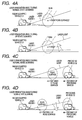
In the case of this embodiment, specifically, the
vehicular radar device 1 can be selectively set to a normal
state in which the optical axis is approximately horizontal
as shown in Fig. 4A (its scanning mode is set to normal), an
up state in which the optical axis is inclined upwardly as
shown in Fig. 4B (the scanning mode is set to up), and a down
state in which the optical axis is inclined downwardly as
shown in Fig. 4D (the scanning mode is set to down). The up
state is a state in which the optical axis is inclined upwardly
to such an extent that at least a road surface lies outside
the detection area (below the detection area) (or, a state
in which the lower side of the angular range of the visual
field is restricted to a narrow range).
The control circuit 17 is a circuit including a
microcomputer made of a CPU, a ROM, a RAM and the like, and
determines whether detection data is relative to unfavorable
weather or the road surface, and realizes adaptive processing
for the unfavorable weather or the road surface, for example,
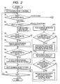
through the process shown in the flowchart of Figs. 2 and 3.
This process will be described below.
In the control circuit 17, when the process is started,
the scanning mode is set to normal in Step S1. Then, in Step
S2, it is determined which of the scanning modes is set at
this point in time. If the scanning mode is set to normal,
the process proceeds to Step S3, if the scanning mode is set
to up, the process proceeds to Step S21, or if the scanning
mode is set to down, the process proceeds to Step S31.
In Step S3, the control circuit 17 analyzes, for each
detection region, received light waveform data obtained by
newly performing scanning (detection operation) at least once
in the normal state, and discriminates between a road surface
(or unfavorable weather) and a vehicle by an existing
discrimination method using the feature quantities of
waveforms (for example, a discrimination method of Patent
Document 5 which compares feature quantities with previously
registered quantities). If the unfavorable weather (such as
rain) or the road surface is detected, the process proceeds
to Step S4; otherwise (if only the vehicle or the like is
detected, or if a target is detected), the process proceeds
to Step S10.
In Step S4, it is determined whether a
road-surface-detected state is set, and if the
road-surface-detected state is set, the process proceeds to
Step S5; otherwise, the process proceeds to Step S6. The
road-surface-detected state is set when a road surface
detection counter which is made to count up in Step S33 (Fig.
3) to be mentioned later reaches a predefined value.
Then, in Step S5, detection data which has been
determined as data relative to the road surface is deleted
(i.e., excluded from targets to be monitored for the purposes
of cruise control and the like), and the process proceeds to
Step S6.
Then, in Step S6, it is determined whether an
unfavorable-weather-detected state is set, and if the
unfavorable-weather-detected state is set, the process
proceeds to Step S7; otherwise, the process proceeds to Step
S8. The unfavorable-weather-detected state is set when an
unfavorable weather detection counter which is made to count
up in Step S23 (Fig. 3) as will be described later reaches
a predefined value.
Then, in Step S7, detection data which has been
determined as data relative to the unfavorable weather
(detection data relative to rain or the like) is deleted (i.e.,
excluded from targets to be monitored for the purposes of
cruise control and the like), and the process proceeds to Step
S8.
Then, in Step S8, the scanning mode is shifted to down
(i.e., the visual field is shifted to a down state), and the
process proceeds to Step S9.
In Step S9, it is determined whether a predetermined end
condition has been satisfied, and if the end condition has
been satisfied, the process is brought to an end. If the end
condition has not been satisfied, the process returns to Step
S2 with predetermined timing corresponding to, for example,
the execution period of scanning, and repeats the processing.
The end condition is a condition which causes the vehicular
radar device 1 to stop its radar operation; for example, the
vehicle stops running, or the ignition key is off.
When the process proceeds to Step S10, if the count value
of the road surface detection counter is not "0", the road
surface detection counter is decremented by one, and the
process proceeds to Step S11.
Then, in Step S11, it is determined whether the
road-surface-detected state which is the result of the
subtraction processing of Step S10 has been reset (for example,
the road surface detection counter has been reset to "0").
Then, if it is determined that the road-surface-detected
state has been reset, processing associated with the
resetting of the road-surface-detected state is executed in
Step S12, and then the process proceeds to Step S13. Otherwise,
the process directly proceeds to Step S13.
The processing associated with the resetting of the
road-surface-detected state is, for example, the processing
of stopping the outputting of a warning which is to be
outputted to a user (driver) during the road-surface-detected
state.
Then, in Step S13, if the count value of the unfavorable
weather detection counter is not "0", the unfavorable weather
detection counter is decremented by one, and the process
proceeds to Step S14.
Then, in Step S14, it is determined whether the
unfavorable-weather-detected state which is the result of the
subtraction processing of Step S13 has been reset (for example,
the unfavorable weather detection counter has been reset to
"0"). Then, if it is determined that the
unfavorable-weather-detected state has been reset,
processing associated with the resetting of the
unfavorable-weather-detected state is executed in Step S15,
and then the process proceeds to Step S9. Otherwise, the
process directly proceeds to Step S9.
The processing associated with the resetting of the
unfavorable-weather-detected state is, for example, the
processing of stopping the outputting of a warning which is
to be outputted to the user (driver) during the
unfavorable-weather-detected state. Otherwise, the
processing may also include the processing of resetting the
setting of making detection performance (transmission power
and reception sensitivity) higher than normal performance,
during the unfavorable-weather-detected state.
On the other hand, if the process proceeds to Step S21
in the branch processing of Step S2 (the scanning mode is set
to up), in Step S21, the control circuit 17 analyzes, for each
detection region, received light waveform data obtained by
newly performing scanning at least once in the up state, and
discriminates between the road surface (or the unfavorable
weather) and the vehicle similarly to Step S3. If the
unfavorable weather or the road surface is detected, the
process proceeds to Step S22; otherwise, the process proceeds
to Step S27.
In Step S22, scanning is again performed if necessary,
and it is determined whether the detection data (received
light quantity or/and distance) which has been determined as
data indicative of the road surface or the like in Step S21
has varied by an amount not smaller than a predefined amount
within a constant time period (i.e., during the execution of
a plurality of detection operations). If the detection data
has not varied, it is determined that the detection data is
relative to the unfavorable weather, and the process proceeds
to Step S23. Otherwise, it is determined that the detection
data is relative to the vehicle or the like, and the process
proceeds to Step S27. Incidentally, if it is determined in
Step S22 that the detection data is relative to the
unfavorable weather, the detection data is deleted in the
above-mentioned Step S7 which is executed after Step S22.
Then, in Step S23, the count value of the unfavorable
weather detection counter is incremented by one, and the
process proceeds to Step S24.
Then, in Step S24, it is determined whether the
unfavorable-weather-detected state which is the result of the
addition processing of Step S23 has been set (for example,
the unfavorable weather detection counter has been set to a
predefined value larger than "0"). Then, if it is determined
that the unfavorable-weather-detected state has been set, the
process proceeds to Step S25. Otherwise, the process proceeds
to Step S26.
Then, in Step S25, processing associated with the
unfavorable-weather-detected state is executed, and the
process proceeds to Step S26. The processing associated with
the unfavorable-weather-detected state is, for example, the
processing of outputting a warning to the user (driver) during
the unfavorable-weather-detected state, or the processing of
making detection performance (transmission power and
reception sensitivity) higher than normal performance during
the unfavorable-weather-detected state.
Then, in Step S26, the scanning mode is shifted to normal
(i.e., the visual field is shifted to a normal state), and
the process proceeds to Step S9.
When the process proceeds to Step S27, if the count value
of the unfavorable weather detection counter is not "0", the
unfavorable weather detection counter is decremented by one,
and the process proceeds to Step S28.
Then, in Step S28, it is determined whether the
unfavorable-weather-detected state which is the result of the
subtraction processing of Step S27 has been reset (for example,
the unfavorable weather detection counter has been reset to
"0"). Then, if it is determined that the
unfavorable-weather-detected state has been reset, the
processing associated with the resetting of the
unfavorable-weather-detected state is executed in Step S29,
and then the process proceeds to Step S26. Otherwise, the
process directly proceeds to Step S26.
On the other hand, if the process proceeds to Step S31
in the branch processing of Step S2 (the scanning mode is set
to down), in Step S31, the control circuit 17 analyzes, for
each detection region, received light waveform data obtained
by newly performing scanning at least once in the down state,
and discriminates between the road surface (or the
unfavorable weather) and the vehicle similarly to Step S3.
If the unfavorable weather or the road surface is detected,
the process proceeds to Step S32; otherwise, the process
proceeds to Step S37.
In Step S32, a comparison is made between the detection
data which has been determined as data indicative of the road
surface or the like in Step S31 and detection data on the same
target which has been obtained through scanning in the
previous normal mode, and it is determined whether these data
(received light quantity or/and distance) have varied by an
amount not smaller than a predefined amount. If the detection
data has varied, it is determined that the detection data is
relative to the road surface, and the process proceeds to Step
S33. Otherwise, it is determined that the detection data is
relative to the vehicle or the unfavorable weather, and the
process proceeds to Step S37. Incidentally, if it is
determined in Step S32 that the detection data is relative
to the road surface, the detection data is deleted in the
above-mentioned Step S5 which is executed after Step S32.
Then, in Step S33, the count value of the road surface
detection counter is incremented by one, and the process
proceeds to Step S34.
Then, in Step S34, it is determined whether the
road-surface-detected state which is the result of the
addition processing of Step S33 has been set (for example,
the road surface detection counter has been set to a
predefined value larger than "0"). Then, if it is determined
that the road-surface-detected state has been set, the
process proceeds to Step S35. Otherwise, the process proceeds
to Step S36.
Then, in Step S35, processing associated with the
road-surface-detected state is executed, and the process
proceeds to Step S36. The processing associated with the
road-surface-detected state is, for example, the processing
of outputting a warning to the user (driver) during the
road-surface-detected state.
Then, in Step S36, the scanning mode is shifted to up
(i.e., the visual field is shifted to an up state), and the
process proceeds to Step S9.
When the process proceeds to Step S37, if the count value
of the road surface detection counter is not "0", the road
surface detection counter is decremented by one, and the
process proceeds to Step S38.
Then, in Step S38, it is determined whether the
road-surface-detected state which is the result of the
subtraction processing of Step S37 has been reset (for example,
the road surface detection counter has been reset to "0").
Then, if it is determined that the road-surface-detected
state has been reset, the processing associated with the
resetting of the road-surface-detected state is executed in
Step S39, and then the process proceeds to Step S36. Otherwise,
the process directly proceeds to Step S36.
According to the above-described sequence of processing,
first, scanning (detection operation) is executed during the
normal state in which the direction of the visual field is
approximately horizontal, and if it is determined from the
received light waveform analysis (a decision based on feature
quantities) that there is data presumed to be detection data
relative to the unfavorable weather (such as rain) or the road
surface, the process proceeds from Step S3 to Step S8, in which
the normal state is shifted to the down state in which the
visual field is inclined downwardly (the scanning mode is set
to down). In the next cycle, the processing for the scanning
mode which is set to down (Steps S31 to S36) is executed. Then,
in the last step (Step S36) of the processing for the scanning
mode which is set to down, the down state is shifted to the
up state in which the visual field is inclined upwardly (the
scanning mode is set to up), and in the subsequent cycle, the
processing for the scanning mode which is set to up (Steps
S21 to S26) is executed. Then, in the last step (Step S26)
of the processing for the scanning mode which is set to up,
the up state is shifted to the normal state in which the
direction of the visual field is approximately horizontal
(the scanning mode is set to normal), and the process returns
to the normal state and repeats Step S3 and the following
steps.
Namely, in this embodiment, the control circuit 17 makes
a target decision as to detection data obtained from a
detection operation in the normal state, on the basis of a
feature quantity of a received waveform (received light
waveform data), and when there exists detection data presumed
to be relative to a road surface, rain or the like (part of
the received light waveform data) (when it is determined that
there is data indicative of rain or the like, or when it is
determined that there is data indicative of the road surface),
the visual field is shifted to make a final decision as to
the road surface or rain or the like.
The final decision as to rain or the like is made in the
following manner. Namely, from among detection data obtained
during the up state, detection data which does not vary for
at least a predefined time in reception intensity nor in
reception delay time (i.e., in received light quantity nor
in distance data) is determined as detection data relative
to rain or the like (Step S22).
The final decision as to the road surface is made in the
following manner. Namely, from among detection data obtained
during the down state, detection data showing a reception
delay time (i.e., distance data) which has varied compared
to a detection operation in the previous normal state is
determined as detection data relative to the road surface
(Step S32).
Accordingly, according to this embodiment, it is
possible to highly reliably discriminate between rain or the
road surface and others (such as a vehicle), and it is possible
to highly appropriately execute processing based on this
discrimination (for example, the processing of issuing a
warning to the user).
The reason for this is as follows. The decision as to
rain or the like is made after the normal state shown in Fig.
4A by way of example (for example, the state in which received
light waveform data such as that shown in Fig. 5A by way of
example is obtained) has been shifted to the up state shown
in Fig. 4A (the state in which the road surface is out of the
visual field). Accordingly, data components relative to at
least the road surface do not appear as received light
waveform data, as shown in Fig. 5B by way of example. At this
time, as the result of the shift of the visual field, data
components relative to an objective vehicle or the like
decrease in received light quantity (reception intensity) or
do not appear as detection data, as shown in Fig. 5B by way
of example. In addition, even if there remains a data
component relative to the objective vehicle or the like, this
data is eliminated in the decision of Step S22 mentioned above,
because as observation is performed for a given time period,
the received light quantity and the distance data necessarily
vary with the running of the vehicle. However, data relative
to unfavorable weather such as rain, even if it is observed
for the given time period, is observed at approximately the
same distance with an approximately constant received light
quantity (i.e., with approximately the same waveform) as
shown in Fig. 5C by way of example. Accordingly, through the
above-described decision, only the detection data relative
to rain or the like can be positively recognized in the state
of being discriminated from the road surface and the obj ective
vehicle or the like.
In addition, the decision as to the road surface is made
after the normal state shown in Fig. 4C by way of example (for
example, the state in which received light waveform data such
as that shown in Fig. 6A by way of example is obtained) has
been shifted to the down state shown in Fig. 4D (the state
in which the road surface is detected as a closer object),
on the basis of a variation in distance data before and after
this shift. At this time, as the result of the shift of the
visual field, data components relative to the road surface
increase in received light quantity (reception intensity) and
the distance data necessarily varies to indicate a closer
distance, as shown in Fig. 6B by way of example. However,
as shown in Fig. 6C by way of example, the data relative to
the objective vehicle or the like or rain or the like may
slightly decrease in received light quantity, but is observed
at approximately the same distance. Accordingly, through the
decision of Step S32 described above, only the detection data
relative to the road surface can be positively recognized in
the state of being discriminated from rain, the objective
vehicle and the like.
In this embodiment, the vehicular radar device makes a
target decision based on a feature quantity of a received
waveform, as to detection data obtained through a detection
operation in the normal state (Step S3), and when there exists
detection data presumed to be relative to the road surface
or rain or the like, shifts the visual field and makes the
decision. Accordingly, the vehicular radar device has the
advantage that it is possible to efficiently discriminate
between the road surface and rain or the like by shifting the
visual field only when necessary, and it is also possible to
prevent power consumption or the like due to useless
operations (such as an unnecessary shift of the visual field).
In this embodiment, the vehicular radar device has a
construction in which in the case where it is to be determined
during the above-described up state or down state whether the
detection data is data relative to rain or the like or the
road surface, the target decision based on the feature
quantity of the received waveform is first performed (Steps
S21 and S31), and only when it is determined that there exists
detection data presumed to be relative to rain or the like
or the road surface, the above-described decision (Steps S22
and S32) is made. Accordingly, the vehicular radar device
has the advantage that, through a comparatively simple target
decision (a decision based on a comparison between the feature
quantity and a previously registered reference value), after
it has been confirmed whether the decision (Steps S22 and S32)
is necessary, the decision can be performed only when
necessary, so that useless decision processing can be
avoided.
In addition, in this embodiment, when it is to be
determined during the up state or the down state whether the
detection data is data relative to rain or the like or the
road surface, the target decision based on the feature
quantity of the received waveform is performed (Steps S21 and
S31), and detection data which is positively not relative to
rain or the like or the road surface is eliminated from
decision targets (Steps S22 and S32). Accordingly, this
embodiment has the advantage that the decision processing
(Steps S22 and S32) is simple.
Furthermore, in this embodiment, when it is determined
that the detection data is relative to the road surface or
rain or the like, or when neither the road surface nor rain
or the like can be detected, the associated processing (for
example, the operation of outputting a warning to the user
or resetting the outputting of this warning) is not
immediately execute, but the associated detection counter
(the road surface detection counter or the unfavorable
weather detection counter) is incremented or decremented
(Steps S10, S13, S23, S27, S33 and S37), and when this
detection counter reaches a predefined count value, it is
determined that the detected state has been set or the
detected state has been reset, and the associated processing
is executed (Steps S24, S28, S34, S38, S11 and S14).
Accordingly, the relationship between the decision operation
and the execution of the associated processing can be given
an appropriate play, so that the operation can be made stable.
For example, during a delicate state which alternates between
detection and undetection of unfavorable weather, it is
possible to avoid unpreferable unstable state in which the
output state of the warning frequently alternates between on
and off states.
The invention is not limited to the above-described
embodiment, and various modifications and variations of the
invention can be made by those skilled in the art.
For example, in the case where the direction or the angle
of the visual field in the up state (the scanning mode is set
to up) can be inclined upwardly to such an extent that no
vehicles can be detected, decision processing such as Step
S22 may also be omitted. In this case, detectable data is
rain or the like with high probability. However, in this case
as well, a construction which makes a final decision as to
rain or the like through processing like Step S22 is
advantageous in terms of the probability that a sign or a
signboard which is installed above the road may be erroneously
recognized as rain or the like. This is because the sign,
the signboard and the like can be positively discriminated
from rain or the like through the processing of Step S22.
Incidentally, the direction of the visual field which
does not detect an objective vehicle or the like (an angle
theta; relative to the horizontal of the central axis of the
visual field) can be calculated, for example, in the following
manner. Namely, assuming that the vehicle height is 2 m, the
installation height of the radar head is 50 cm, the angle of
the visual field is 6 degrees, and rain or the like is detected
at a distance of nearly 5 m, the angle theta; ≥ approximately
20 deg; (= arctan((2 - 0.5) divide; 5) + (6 divide; 2).
In addition, when it is to be determined whether a road
surface has been detected, from a variation occurring in
distance data due to a shift to the down state (the scanning
mode is set to down) (for example, the decision of Step S32),
only detection data which varies in the direction in which
its reception delay time (i.e., distance data) becomes
shorter may be determined as detection data relative to the
road surface so that the reliability of the decision can be
further improved.
In addition, when it is to be determined whether a road
surface has been detected, only detection data whose
reception delay time is within a predefined range may also
be determined as detection data relative to the road surface
so that the reliability of the decision can be further
improved. Incidentally, the predefined range may be set to,
for example, an area close to a distance at which data relative
to the road surface is presumed to occur (road-surface
occurrence distance). The road-surface occurrence distance
can be easily estimated from the installation height of the
radar head and the angle of the optical axis by using a
trigonometric function.
The above-described embodiment provides a construction
which executes both the operation of inclining the visual
field upwardly to make a decision as to rain or the like and
the operation of inclining the visual field downwardly to make
a decision as to a road surface, but can also provide a
construction which executes either one of these operations.
Only by executing either one of the operations, it is possible
to positive make a decision as to either one of a road surface
and rain or the like, so that the other one can be easily
discriminated by an existing decision method. For example,
if the operation of inclining the visual field downwardly to
make a decision as to a road surface is executed, detection
data excluding detection data which is determined as data
relative to the road surface can be detected by discriminating
between rain or the like and a vehicle or the like, on the
basis of an existing decision based on received waveforms.
In addition, it is possible to adopt a construction
which, when a predefined interval time elapses (i.e.,
periodically), executes the operation of inclining the visual
field upwardly to make a decision as to rain or the like and
the operation of inclining the visual field downwardly to make
a decision as to a road surface. It is also possible to adopt
another construction which performs the above-described
operation once each time scanning is performed by a
predetermined number of times in the normal state.
Although the invention can be applied to a vehicular
radar device which performs scanning in the horizontal
direction (in the rightward and leftward directions) as in
the above-described embodiment, the invention can also be
applied to a vehicular radar device which performs scanning
in the vertical direction or a vehicular radar device which
performs scanning in two directions, i.e., the vertical
direction and the horizontal direction. Scanning is not
limited to the above-mentioned rotational operation, and may
also make use of rectilinear movement (slide) of an emission
part or the like.
Only the transmitting side may be constructed to perform
scanning, but if the state of reception is to be maintained
irrespective of the position of scanning so that a far better
distance measuring operation can be performed, it is
desirable that scanning be also performed on the receiving
side. For example, the receiving head may be constructed to
perform scanning in synchronism with the transmitting side.
The invention can be applied to not only vehicular radar
devices using laser light, but also vehicular radar devices
using, for example, radio waves. However, since laser light
has the nature that its distance performance becomes
particularly low due to rain and the like, the invention is
particularly useful in application to a laser type of radar
device.