EP1500926A1 - Verfahren zur Kompensation der Alterung eines Sensors zur Erfassung einer Gaskonzentration - Google Patents
Verfahren zur Kompensation der Alterung eines Sensors zur Erfassung einer Gaskonzentration Download PDFInfo
- Publication number
- EP1500926A1 EP1500926A1 EP04016940A EP04016940A EP1500926A1 EP 1500926 A1 EP1500926 A1 EP 1500926A1 EP 04016940 A EP04016940 A EP 04016940A EP 04016940 A EP04016940 A EP 04016940A EP 1500926 A1 EP1500926 A1 EP 1500926A1
- Authority
- EP
- European Patent Office
- Prior art keywords
- sensor
- aging
- compensating
- heated
- resistance value
- Prior art date
- Legal status (The legal status is an assumption and is not a legal conclusion. Google has not performed a legal analysis and makes no representation as to the accuracy of the status listed.)
- Granted
Links
- 230000032683 aging Effects 0.000 title claims abstract description 20
- 238000000034 method Methods 0.000 title claims abstract description 20
- 238000010438 heat treatment Methods 0.000 claims abstract description 7
- 238000012544 monitoring process Methods 0.000 claims abstract 2
- 238000012423 maintenance Methods 0.000 claims description 3
- 230000005540 biological transmission Effects 0.000 claims description 2
- 238000005259 measurement Methods 0.000 claims description 2
- 238000009434 installation Methods 0.000 abstract 1
- 239000007789 gas Substances 0.000 description 26
- UGFAIRIUMAVXCW-UHFFFAOYSA-N Carbon monoxide Chemical compound [O+]#[C-] UGFAIRIUMAVXCW-UHFFFAOYSA-N 0.000 description 20
- 229910002091 carbon monoxide Inorganic materials 0.000 description 17
- 230000001419 dependent effect Effects 0.000 description 3
- VNWKTOKETHGBQD-UHFFFAOYSA-N methane Chemical compound C VNWKTOKETHGBQD-UHFFFAOYSA-N 0.000 description 2
- 229910005191 Ga 2 O 3 Inorganic materials 0.000 description 1
- 241001101998 Galium Species 0.000 description 1
- 235000006679 Mentha X verticillata Nutrition 0.000 description 1
- 235000002899 Mentha suaveolens Nutrition 0.000 description 1
- 235000001636 Mentha x rotundifolia Nutrition 0.000 description 1
- 239000003570 air Substances 0.000 description 1
- 239000012080 ambient air Substances 0.000 description 1
- 230000007423 decrease Effects 0.000 description 1
- 238000001514 detection method Methods 0.000 description 1
- 230000000694 effects Effects 0.000 description 1
- 238000011156 evaluation Methods 0.000 description 1
- 230000000977 initiatory effect Effects 0.000 description 1
- 239000000203 mixture Substances 0.000 description 1
- 239000003345 natural gas Substances 0.000 description 1
- 230000000630 rising effect Effects 0.000 description 1
- 230000035945 sensitivity Effects 0.000 description 1
Images



Classifications
-
- G—PHYSICS
- G01—MEASURING; TESTING
- G01N—INVESTIGATING OR ANALYSING MATERIALS BY DETERMINING THEIR CHEMICAL OR PHYSICAL PROPERTIES
- G01N33/00—Investigating or analysing materials by specific methods not covered by groups G01N1/00 - G01N31/00
- G01N33/0004—Gaseous mixtures, e.g. polluted air
- G01N33/0006—Calibrating gas analysers
Definitions
- the invention relates to a method for compensating the aging of a sensor for detecting a gas concentration.
- sensors are used, for example, in natural gas or oil-fired heating systems used to optimize fuel-air ratio to be able to adjust.
- Gas sensors usually operate at operating temperatures above the temperature of the sample gas to be examined.
- Galium oxide sensors Ga 2 O 3
- the sensor element is usually heated by a mounted on its rear electrical heating element.
- the sensitivity of a gas sensor is temperature-dependent. This means that Output signal of the sensor with the same gas composition when changing the Sensor temperature fluctuates. It is therefore necessary to have a gas sensor at a constant Operating temperature to operate.
- the invention is therefore based on the object, a method for detection and Compensation of the aging of a sensor to detect a gas concentration create.
- This object is achieved by means of a method having the features according to claim 1 achieved in that the operating temperature of the sensor is increased. In certain cases - There are also sensors in which the resistance increases with increasing temperature - It may be necessary to reduce the operating temperature to the same effect to achieve. This also changes the output signal, so that the signal again can be meaningfully evaluated.
- Resistance of the sensor can be determined as a measure of the measured variable.
- the aging compensation then becomes carried out when the gas concentration to be detected is not present.
- lie Reference conditions lie Reference conditions.
- the compensation was at least partially withdrawn to see if the change was only temporary and the sensor is back has regenerated. If this is the case, the temperature is reduced again.
- a signal issued for initiation of maintenance can be, for example, an ad on a Display or a message via data line or wireless connection to one Be a specialist.
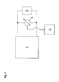
- Figure 1 shows a very simplified circuit with a sensor for detecting the Gas concentration.
- a constant current source 1 is connected to a sensor 2 for detecting the Gas concentration preferably in the exhaust path of a heating system, connected.
- Parallel to the sensor 2 a voltage measuring device 3 is arranged.
- the tension measuring device 3 again with an operational amplifier 4 which amplifies the output signal, connected.
- FIG. 2 shows the relationship between a measuring gas, in this case carbon monoxide (CO), and the resistance of a sensor for detecting a gas concentration.
- a measuring gas in this case carbon monoxide (CO)
- CO carbon monoxide
- the temperature the sensor is constant. If there is no carbon monoxide, then the resistance a certain value. With the increase in carbon monoxide concentration decreases Resistance steadily.
- Figure 3 shows the relationship between the operating temperature of the sensor and the Resistance of the sensor at constant sample gas. One can recognize that with rising Temperature of resistance drops.
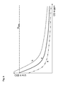
- Figure 4 shows the signal that at a voltmeter parallel to a gas sensor is connected, is present, provided that the current and the temperature are constant. With increasing sample gas concentration drops the voltage.
- Line a shows the relationship between sample gas and output voltage in mint condition. If the sensor ages and, accordingly, changes its resistance, a characteristic according to b would arise. At low carbon monoxide concentrations, however, the voltage would be higher than the supply voltage U vers . Accordingly, the operating temperature of the sensor 2 is increased, whereby the resistance drops. Accordingly, a ratio according to the line c is established. It can be seen here that, without the presence of the relevant gas (carbon monoxide), a maximum voltage in the amount of the supply voltage is established.
- the relationship between the measured variable and the output variable is the same second independent claim of the inventive method shown.
- the line d shows the ratio in the aged state. From this it would emerge that the Output voltage higher than the supply voltage would be. Accordingly, the Ratio adjusted so that according to line e, even at high measurement signal the Output signal is below the supply voltage.
- the measured voltage can be changed (see. Fig. 5). The sensor temperature is changed so that a defined Output voltage in the above reference gas is present, preferably the Supply voltage or a value slightly below this.
- the advantage of the method described is that the sensor life significantly can be extended. In addition, it is possible to have a high resolution even with aged ones Enable sensor.
- control detects this, and a Signal to initiate maintenance and repair.
- This can be a Telecommunication connection of the device in which the sensor is located, over the e.g. a mail or an SMS is sent to a specialist tradesman.
Landscapes
- Chemical & Material Sciences (AREA)
- Life Sciences & Earth Sciences (AREA)
- Engineering & Computer Science (AREA)
- Health & Medical Sciences (AREA)
- Analytical Chemistry (AREA)
- General Physics & Mathematics (AREA)
- Medicinal Chemistry (AREA)
- Physics & Mathematics (AREA)
- Combustion & Propulsion (AREA)
- Biochemistry (AREA)
- General Health & Medical Sciences (AREA)
- Food Science & Technology (AREA)
- Immunology (AREA)
- Pathology (AREA)
- Investigating Or Analyzing Materials By The Use Of Fluid Adsorption Or Reactions (AREA)
- Investigating Or Analysing Materials By Optical Means (AREA)
- Investigating Or Analyzing Materials By The Use Of Electric Means (AREA)
- Measuring Oxygen Concentration In Cells (AREA)
Abstract
Description
Claims (8)
- Verfahren zur Kompensation der Alterung eines beheizten Sensors (2) zur Erfassung einer Gaskonzentration vorzugsweise im Abgasweg einer Heizungsanlage, dadurch gekennzeichnet, dass bei Über- oder Unterschreitung eines vorgegebenen Widerstandswertes des Sensors (2) die Betriebstemperatur des Sensors (2) erhöht oder reduziert wird.
- Verfahren zur Kompensation der Alterung eines beheizten Sensors (2) gemäß Anspruch 1, dadurch gekennzeichnet, dass zur Messung des Widerstandswertes des Sensors (2) der Sensor (2) an eine Konstantstromquelle (1) angeschlossen wird und die sich ergebende Spannung gemessen wird.
- Verfahren zur Kompensation der Alterung eines beheizten Sensors (2) gemäß Anspruch 1, dadurch gekennzeichnet, dass zur Messung des Widerstandswertes des Sensors (2) der Sensor (2) an eine Konstantspannungsquelle angeschlossen wird und der sich ergebende Strom gemessen wird.
- Verfahren zur Kompensation der Alterung eines beheizten Sensors (2) gemäß einem der Ansprüche 1 bis 3, dadurch gekennzeichnet, dass die Kompensation der Alterung durchgeführt wird, wenn die zu erfassende Gaskonzentration nicht vorliegt.
- Verfahren zur Kompensation der Alterung eines beheizten Sensors (2) gemäß einem der Ansprüche 1 bis 4, dadurch gekennzeichnet, dass die Betriebstemperatur des Sensors (2) erhöht oder reduziert wird, bis das Messsignal einen bestimmten Grenzwert unter- bzw. überschreitet.
- Verfahren zur Kompensation der Alterung eines beheizten Sensors (2) gemäß einem der Ansprüche 1 bis 5, dadurch gekennzeichnet, dass nach einer bestimmten Betriebszeit des Sensors (2) die Betriebstemperatur des Sensors (2) wieder reduziert oder erhöht wird und in dem Fall, in eine Unterschreitung eines vorgegebenen Widerstandswertes des Sensors (2) vorliegt, der Sensor (2) wieder mit reduzierter oder erhöhter Betriebstemperatur betrieben wird.
- Verfahren zur Kompensation der Alterung eines beheizten Sensors (2) zur Erfassung einer Gaskonzentration vorzugsweise im Abgasweg einer Heizungsanlage mit einem Operationsverstärker (4) zur Auswertung des Signals, dadurch gekennzeichnet, dass bei Überschreitung eines vorgegebenen Widerstandswertes des Sensors (2) das Übersetzungsverhältnis eines Operationsverstärkers (4) verändert wird, vorzugsweise dahingehend, dass das Ausgangssignal reduziert wird.
- Verfahren zur Überwachung der Alterung eines beheizten Sensors (2) zur Erfassung einer Gaskonzentration vorzugsweise im Abgasweg einer Heizungsanlage mit einem Operationsverstärker (4) zur Auswertung des Signals, dadurch gekennzeichnet, dass bei Überschreitung eines vorgegebenen Widerstandswertes des Sensors (2) eine Fehlermeldung auf einem Display und / oder über eine Datenleitung ein Wartungssignal ausgegeben wird.
Priority Applications (1)
| Application Number | Priority Date | Filing Date | Title |
|---|---|---|---|
| PL04016940T PL1500926T3 (pl) | 2003-07-21 | 2004-07-19 | Sposób kompensacji starzenia się czujnika do wykrywania koncentracji gazu |
Applications Claiming Priority (2)
| Application Number | Priority Date | Filing Date | Title |
|---|---|---|---|
| AT11342003 | 2003-07-21 | ||
| AT11342003 | 2003-07-21 |
Publications (2)
| Publication Number | Publication Date |
|---|---|
| EP1500926A1 true EP1500926A1 (de) | 2005-01-26 |
| EP1500926B1 EP1500926B1 (de) | 2009-08-19 |
Family
ID=33479919
Family Applications (1)
| Application Number | Title | Priority Date | Filing Date |
|---|---|---|---|
| EP04016940A Expired - Lifetime EP1500926B1 (de) | 2003-07-21 | 2004-07-19 | Verfahren zur Kompensation der Alterung eines Sensors zur Erfassung einer Gaskonzentration |
Country Status (7)
| Country | Link |
|---|---|
| EP (1) | EP1500926B1 (de) |
| AT (1) | ATE440277T1 (de) |
| DE (2) | DE102004035177A1 (de) |
| DK (1) | DK1500926T3 (de) |
| ES (1) | ES2329998T3 (de) |
| PL (1) | PL1500926T3 (de) |
| PT (1) | PT1500926E (de) |
Families Citing this family (1)
| Publication number | Priority date | Publication date | Assignee | Title |
|---|---|---|---|---|
| DE102017109564A1 (de) * | 2017-05-04 | 2018-11-08 | Endress+Hauser Conducta Gmbh+Co. Kg | Verfahren zur Zustandsbestimmung von Sensoren |
Citations (3)
| Publication number | Priority date | Publication date | Assignee | Title |
|---|---|---|---|---|
| EP0453062A1 (de) * | 1990-02-12 | 1991-10-23 | Ford Motor Company Limited | Gerät und Verfahren zur Reduzierung von Schadstoffemission im Abgas der Brennkraftmaschine eines Kraftfahrzeuges |
| DE19522347C1 (de) * | 1995-06-20 | 1996-09-19 | Siemens Ag | Verfahren und Anordnung zur Stabilisierung der Temperatur eines Heizelementes für einen Gassensor |
| DE19516974A1 (de) * | 1995-04-07 | 1996-10-10 | Landis & Gyr Tech Innovat | Photoakustischer Gassensor |
Family Cites Families (2)
| Publication number | Priority date | Publication date | Assignee | Title |
|---|---|---|---|---|
| DE4344961B4 (de) * | 1993-12-30 | 2004-05-06 | Robert Bosch Gmbh | Auswertevorrichtung für das Signal einer Sauerstoffsonde |
| US5852228A (en) * | 1996-07-10 | 1998-12-22 | Denso Corporation | Apparatus and method for controlling oxygen sensor heating |
-
2004
- 2004-07-16 DE DE102004035177A patent/DE102004035177A1/de not_active Withdrawn
- 2004-07-19 AT AT04016940T patent/ATE440277T1/de active
- 2004-07-19 PT PT04016940T patent/PT1500926E/pt unknown
- 2004-07-19 ES ES04016940T patent/ES2329998T3/es not_active Expired - Lifetime
- 2004-07-19 DE DE502004009912T patent/DE502004009912D1/de not_active Expired - Lifetime
- 2004-07-19 DK DK04016940T patent/DK1500926T3/da active
- 2004-07-19 EP EP04016940A patent/EP1500926B1/de not_active Expired - Lifetime
- 2004-07-19 PL PL04016940T patent/PL1500926T3/pl unknown
Patent Citations (3)
| Publication number | Priority date | Publication date | Assignee | Title |
|---|---|---|---|---|
| EP0453062A1 (de) * | 1990-02-12 | 1991-10-23 | Ford Motor Company Limited | Gerät und Verfahren zur Reduzierung von Schadstoffemission im Abgas der Brennkraftmaschine eines Kraftfahrzeuges |
| DE19516974A1 (de) * | 1995-04-07 | 1996-10-10 | Landis & Gyr Tech Innovat | Photoakustischer Gassensor |
| DE19522347C1 (de) * | 1995-06-20 | 1996-09-19 | Siemens Ag | Verfahren und Anordnung zur Stabilisierung der Temperatur eines Heizelementes für einen Gassensor |
Also Published As
| Publication number | Publication date |
|---|---|
| ATE440277T1 (de) | 2009-09-15 |
| DK1500926T3 (da) | 2009-12-14 |
| EP1500926B1 (de) | 2009-08-19 |
| PL1500926T3 (pl) | 2010-01-29 |
| DE502004009912D1 (de) | 2009-10-01 |
| DE102004035177A1 (de) | 2005-02-10 |
| ES2329998T3 (es) | 2009-12-03 |
| PT1500926E (pt) | 2009-10-20 |
Similar Documents
| Publication | Publication Date | Title |
|---|---|---|
| DE3115404C2 (de) | ||
| DE69821410T2 (de) | Gassensor | |
| EP1736745A1 (de) | Verfahren zur adaptiven Korrektur von Drifterscheinungen bei einer Kraftmessvorrichtung sowie eine Kraftmessvorrichtung zur Durchführung des Verfahrens. | |
| DE102015207895A1 (de) | Verfahren zur Überwachung eines elektronischen Steuergeräts und Steuergerät für ein Kraftfahrzeug | |
| EP0377600B1 (de) | Verfahren, anwendung desselben und vorrichtung zur lambdawerterfassung | |
| DE102010041693B4 (de) | Verfahren zum Prüfen der Funktionsfähigkeit eines photoelektrischen Rauchmelders sowie Rauchmelder zur Durchführung des Verfahrens | |
| EP1697687B1 (de) | Verfahren zur ermittlung schwankender brennstoffeigenschaften während des betriebs einer kraftwerksanlage | |
| DE102012222935B4 (de) | Verfahren und System zur Überwachung einer Schwankung einer Wandlerspannungsreferenz | |
| WO2009130266A1 (de) | Ansteuerschaltung für einen elektrochemischen gassensor und verfahren zum einstellen eines elektrochemischen gassensors | |
| EP1500926B1 (de) | Verfahren zur Kompensation der Alterung eines Sensors zur Erfassung einer Gaskonzentration | |
| EP3640652B1 (de) | Verfahren zum betrieb eines batteriesensors und batteriesensor | |
| EP3712570A1 (de) | Verfahren und anordnung zur messung eines strömungsparameters in oder an einer von einem fluid durchströmbaren vorrichtung | |
| DE102008027585B4 (de) | Kalibrierung der Piezoparameter für eine Zylinderinnendruckmessung mittels Piezoinjektoren | |
| DE19530316C1 (de) | Diagnoseverfahren für einen Abgassensor | |
| DE102008043407B4 (de) | Verfahren und Vorrichtung zur Erkennung von Manipulationen an Lambdasonden | |
| EP1680771A1 (de) | Verfahren zur identifikation von analogen messsignalgebern und zugehörige anordnung | |
| EP2581890B1 (de) | Verfahren zur Erhöhung der Fehlalarmsicherheit eines Brandmelders | |
| DE4323380A1 (de) | Verfahren und Schaltung zur Fehlererkennung bei Widerstands-Meßbrücken | |
| WO2009040293A1 (de) | Verfahren und vorrichtung zum bestimmen einer dynamischen eigenschaft eines abgassensors | |
| DE102017101079A1 (de) | Verfahren und Vorrichtung zur Bestimmung und/oder Überwachung des Zustandes einer Schutzabdeckung | |
| DE102008061996B4 (de) | Messverfahren für Ströme mit unterschiedlichen Messbereichen | |
| DE102008026741B4 (de) | Verfahren zum Erfassen der Funktionsfähigkeit einer Lambda-Sonde in einem geregelten System | |
| EP3812645A1 (de) | Vorrichtung zum ermitteln eines verbrauchs eines gases aus einer zumindest teilweise mit gas gefüllten gasflasche | |
| DE102018205921A1 (de) | Verfahren zum Erzeugen eines Ausgangssignals | |
| DE19821136C2 (de) | Vorrichtung zur Analyse des Abgases von Kraftfahrzeugen |
Legal Events
| Date | Code | Title | Description |
|---|---|---|---|
| PUAI | Public reference made under article 153(3) epc to a published international application that has entered the european phase |
Free format text: ORIGINAL CODE: 0009012 |
|
| AK | Designated contracting states |
Kind code of ref document: A1 Designated state(s): AT BE BG CH CY CZ DE DK EE ES FI FR GB GR HU IE IT LI LU MC NL PL PT RO SE SI SK TR |
|
| AX | Request for extension of the european patent |
Extension state: AL HR LT LV MK |
|
| 17P | Request for examination filed |
Effective date: 20050622 |
|
| AKX | Designation fees paid |
Designated state(s): AT BE BG CH CY CZ DE DK EE ES FI FR GB GR HU IE IT LI LU MC NL PL PT RO SE SI SK TR |
|
| 17Q | First examination report despatched |
Effective date: 20080110 |
|
| GRAP | Despatch of communication of intention to grant a patent |
Free format text: ORIGINAL CODE: EPIDOSNIGR1 |
|
| GRAS | Grant fee paid |
Free format text: ORIGINAL CODE: EPIDOSNIGR3 |
|
| GRAA | (expected) grant |
Free format text: ORIGINAL CODE: 0009210 |
|
| AK | Designated contracting states |
Kind code of ref document: B1 Designated state(s): AT BE BG CH CY CZ DE DK EE ES FI FR GB GR HU IE IT LI LU MC NL PL PT RO SE SI SK TR |
|
| REG | Reference to a national code |
Ref country code: GB Ref legal event code: FG4D Free format text: NOT ENGLISH |
|
| REG | Reference to a national code |
Ref country code: CH Ref legal event code: EP |
|
| REG | Reference to a national code |
Ref country code: IE Ref legal event code: FG4D |
|
| REF | Corresponds to: |
Ref document number: 502004009912 Country of ref document: DE Date of ref document: 20091001 Kind code of ref document: P |
|
| REG | Reference to a national code |
Ref country code: PT Ref legal event code: SC4A Free format text: AVAILABILITY OF NATIONAL TRANSLATION Effective date: 20091013 |
|
| REG | Reference to a national code |
Ref country code: SE Ref legal event code: TRGR |
|
| REG | Reference to a national code |
Ref country code: ES Ref legal event code: FG2A Ref document number: 2329998 Country of ref document: ES Kind code of ref document: T3 |
|
| REG | Reference to a national code |
Ref country code: DK Ref legal event code: T3 |
|
| PG25 | Lapsed in a contracting state [announced via postgrant information from national office to epo] |
Ref country code: FI Free format text: LAPSE BECAUSE OF FAILURE TO SUBMIT A TRANSLATION OF THE DESCRIPTION OR TO PAY THE FEE WITHIN THE PRESCRIBED TIME-LIMIT Effective date: 20090819 |
|
| REG | Reference to a national code |
Ref country code: PL Ref legal event code: T3 |
|
| REG | Reference to a national code |
Ref country code: SK Ref legal event code: T3 Ref document number: E 6322 Country of ref document: SK |
|
| PG25 | Lapsed in a contracting state [announced via postgrant information from national office to epo] |
Ref country code: SI Free format text: LAPSE BECAUSE OF FAILURE TO SUBMIT A TRANSLATION OF THE DESCRIPTION OR TO PAY THE FEE WITHIN THE PRESCRIBED TIME-LIMIT Effective date: 20090819 |
|
| PG25 | Lapsed in a contracting state [announced via postgrant information from national office to epo] |
Ref country code: CY Free format text: LAPSE BECAUSE OF FAILURE TO SUBMIT A TRANSLATION OF THE DESCRIPTION OR TO PAY THE FEE WITHIN THE PRESCRIBED TIME-LIMIT Effective date: 20090819 Ref country code: BG Free format text: LAPSE BECAUSE OF FAILURE TO SUBMIT A TRANSLATION OF THE DESCRIPTION OR TO PAY THE FEE WITHIN THE PRESCRIBED TIME-LIMIT Effective date: 20091119 |
|
| PG25 | Lapsed in a contracting state [announced via postgrant information from national office to epo] |
Ref country code: EE Free format text: LAPSE BECAUSE OF FAILURE TO SUBMIT A TRANSLATION OF THE DESCRIPTION OR TO PAY THE FEE WITHIN THE PRESCRIBED TIME-LIMIT Effective date: 20090819 Ref country code: RO Free format text: LAPSE BECAUSE OF FAILURE TO SUBMIT A TRANSLATION OF THE DESCRIPTION OR TO PAY THE FEE WITHIN THE PRESCRIBED TIME-LIMIT Effective date: 20090819 |
|
| PLBE | No opposition filed within time limit |
Free format text: ORIGINAL CODE: 0009261 |
|
| STAA | Information on the status of an ep patent application or granted ep patent |
Free format text: STATUS: NO OPPOSITION FILED WITHIN TIME LIMIT |
|
| 26N | No opposition filed |
Effective date: 20100520 |
|
| PG25 | Lapsed in a contracting state [announced via postgrant information from national office to epo] |
Ref country code: GR Free format text: LAPSE BECAUSE OF FAILURE TO SUBMIT A TRANSLATION OF THE DESCRIPTION OR TO PAY THE FEE WITHIN THE PRESCRIBED TIME-LIMIT Effective date: 20091120 |
|
| BERE | Be: lapsed |
Owner name: VAILLANT G.M.B.H. Effective date: 20100731 |
|
| PG25 | Lapsed in a contracting state [announced via postgrant information from national office to epo] |
Ref country code: MC Free format text: LAPSE BECAUSE OF NON-PAYMENT OF DUE FEES Effective date: 20100731 |
|
| PG25 | Lapsed in a contracting state [announced via postgrant information from national office to epo] |
Ref country code: BE Free format text: LAPSE BECAUSE OF NON-PAYMENT OF DUE FEES Effective date: 20100731 |
|
| PG25 | Lapsed in a contracting state [announced via postgrant information from national office to epo] |
Ref country code: LU Free format text: LAPSE BECAUSE OF NON-PAYMENT OF DUE FEES Effective date: 20100719 Ref country code: HU Free format text: LAPSE BECAUSE OF FAILURE TO SUBMIT A TRANSLATION OF THE DESCRIPTION OR TO PAY THE FEE WITHIN THE PRESCRIBED TIME-LIMIT Effective date: 20100220 |
|
| PG25 | Lapsed in a contracting state [announced via postgrant information from national office to epo] |
Ref country code: TR Free format text: LAPSE BECAUSE OF FAILURE TO SUBMIT A TRANSLATION OF THE DESCRIPTION OR TO PAY THE FEE WITHIN THE PRESCRIBED TIME-LIMIT Effective date: 20090819 |
|
| REG | Reference to a national code |
Ref country code: FR Ref legal event code: PLFP Year of fee payment: 13 |
|
| REG | Reference to a national code |
Ref country code: FR Ref legal event code: ST Effective date: 20180330 |
|
| PG25 | Lapsed in a contracting state [announced via postgrant information from national office to epo] |
Ref country code: FR Free format text: LAPSE BECAUSE OF NON-PAYMENT OF DUE FEES Effective date: 20170731 |
|
| PGFP | Annual fee paid to national office [announced via postgrant information from national office to epo] |
Ref country code: CH Payment date: 20180629 Year of fee payment: 15 Ref country code: PT Payment date: 20180621 Year of fee payment: 15 |
|
| REG | Reference to a national code |
Ref country code: FR Ref legal event code: RN Effective date: 20180927 |
|
| PGFP | Annual fee paid to national office [announced via postgrant information from national office to epo] |
Ref country code: FR Payment date: 20180718 Year of fee payment: 17 Ref country code: SE Payment date: 20180725 Year of fee payment: 15 |
|
| PG25 | Lapsed in a contracting state [announced via postgrant information from national office to epo] |
Ref country code: FR Free format text: LAPSE BECAUSE OF NON-PAYMENT OF DUE FEES Effective date: 20170731 |
|
| PGRI | Patent reinstated in contracting state [announced from national office to epo] |
Ref country code: FR Effective date: 20190204 |
|
| PGFP | Annual fee paid to national office [announced via postgrant information from national office to epo] |
Ref country code: NL Payment date: 20190701 Year of fee payment: 16 |
|
| PGFP | Annual fee paid to national office [announced via postgrant information from national office to epo] |
Ref country code: DK Payment date: 20190703 Year of fee payment: 16 Ref country code: IT Payment date: 20190731 Year of fee payment: 16 Ref country code: GB Payment date: 20190626 Year of fee payment: 16 Ref country code: ES Payment date: 20190808 Year of fee payment: 16 Ref country code: DE Payment date: 20190701 Year of fee payment: 16 |
|
| PGFP | Annual fee paid to national office [announced via postgrant information from national office to epo] |
Ref country code: PL Payment date: 20190702 Year of fee payment: 16 |
|
| PGFP | Annual fee paid to national office [announced via postgrant information from national office to epo] |
Ref country code: AT Payment date: 20190701 Year of fee payment: 16 |
|
| REG | Reference to a national code |
Ref country code: CH Ref legal event code: PL |
|
| REG | Reference to a national code |
Ref country code: SE Ref legal event code: EUG |
|
| REG | Reference to a national code |
Ref country code: SK Ref legal event code: MM4A Ref document number: E 6322 Country of ref document: SK Effective date: 20190719 |
|
| PG25 | Lapsed in a contracting state [announced via postgrant information from national office to epo] |
Ref country code: PT Free format text: LAPSE BECAUSE OF NON-PAYMENT OF DUE FEES Effective date: 20200120 Ref country code: SE Free format text: LAPSE BECAUSE OF NON-PAYMENT OF DUE FEES Effective date: 20190720 |
|
| PG25 | Lapsed in a contracting state [announced via postgrant information from national office to epo] |
Ref country code: LI Free format text: LAPSE BECAUSE OF NON-PAYMENT OF DUE FEES Effective date: 20190731 Ref country code: CZ Free format text: LAPSE BECAUSE OF NON-PAYMENT OF DUE FEES Effective date: 20190719 Ref country code: SK Free format text: LAPSE BECAUSE OF NON-PAYMENT OF DUE FEES Effective date: 20190719 Ref country code: CH Free format text: LAPSE BECAUSE OF NON-PAYMENT OF DUE FEES Effective date: 20190731 |
|
| PG25 | Lapsed in a contracting state [announced via postgrant information from national office to epo] |
Ref country code: IE Free format text: LAPSE BECAUSE OF NON-PAYMENT OF DUE FEES Effective date: 20190719 |
|
| REG | Reference to a national code |
Ref country code: DE Ref legal event code: R119 Ref document number: 502004009912 Country of ref document: DE |
|
| REG | Reference to a national code |
Ref country code: DK Ref legal event code: EBP Effective date: 20200731 |
|
| REG | Reference to a national code |
Ref country code: NL Ref legal event code: MM Effective date: 20200801 |
|
| REG | Reference to a national code |
Ref country code: AT Ref legal event code: MM01 Ref document number: 440277 Country of ref document: AT Kind code of ref document: T Effective date: 20200719 |
|
| GBPC | Gb: european patent ceased through non-payment of renewal fee |
Effective date: 20200719 |
|
| PG25 | Lapsed in a contracting state [announced via postgrant information from national office to epo] |
Ref country code: FR Free format text: LAPSE BECAUSE OF NON-PAYMENT OF DUE FEES Effective date: 20200731 Ref country code: GB Free format text: LAPSE BECAUSE OF NON-PAYMENT OF DUE FEES Effective date: 20200719 Ref country code: NL Free format text: LAPSE BECAUSE OF NON-PAYMENT OF DUE FEES Effective date: 20200801 |
|
| PG25 | Lapsed in a contracting state [announced via postgrant information from national office to epo] |
Ref country code: DE Free format text: LAPSE BECAUSE OF NON-PAYMENT OF DUE FEES Effective date: 20210202 Ref country code: AT Free format text: LAPSE BECAUSE OF NON-PAYMENT OF DUE FEES Effective date: 20200719 |
|
| PG25 | Lapsed in a contracting state [announced via postgrant information from national office to epo] |
Ref country code: DK Free format text: LAPSE BECAUSE OF NON-PAYMENT OF DUE FEES Effective date: 20200731 |
|
| REG | Reference to a national code |
Ref country code: ES Ref legal event code: FD2A Effective date: 20211228 |
|
| PG25 | Lapsed in a contracting state [announced via postgrant information from national office to epo] |
Ref country code: ES Free format text: LAPSE BECAUSE OF NON-PAYMENT OF DUE FEES Effective date: 20200720 |
|
| PG25 | Lapsed in a contracting state [announced via postgrant information from national office to epo] |
Ref country code: IT Free format text: LAPSE BECAUSE OF NON-PAYMENT OF DUE FEES Effective date: 20200719 |
|
| PG25 | Lapsed in a contracting state [announced via postgrant information from national office to epo] |
Ref country code: PL Free format text: LAPSE BECAUSE OF NON-PAYMENT OF DUE FEES Effective date: 20200719 |