EP1500894A2 - Fin-and-tube type heat exchanger - Google Patents
Fin-and-tube type heat exchanger Download PDFInfo
- Publication number
- EP1500894A2 EP1500894A2 EP04077006A EP04077006A EP1500894A2 EP 1500894 A2 EP1500894 A2 EP 1500894A2 EP 04077006 A EP04077006 A EP 04077006A EP 04077006 A EP04077006 A EP 04077006A EP 1500894 A2 EP1500894 A2 EP 1500894A2
- Authority
- EP
- European Patent Office
- Prior art keywords
- louvers
- fins
- heat exchanger
- set forth
- bank
- Prior art date
- Legal status (The legal status is an assumption and is not a legal conclusion. Google has not performed a legal analysis and makes no representation as to the accuracy of the status listed.)
- Withdrawn
Links
- 238000011144 upstream manufacturing Methods 0.000 claims abstract description 12
- 125000006850 spacer group Chemical group 0.000 claims description 5
- 239000002826 coolant Substances 0.000 description 1
- 238000004519 manufacturing process Methods 0.000 description 1
- 238000012986 modification Methods 0.000 description 1
- 230000004048 modification Effects 0.000 description 1
Images


Classifications
-
- F—MECHANICAL ENGINEERING; LIGHTING; HEATING; WEAPONS; BLASTING
- F28—HEAT EXCHANGE IN GENERAL
- F28F—DETAILS OF HEAT-EXCHANGE AND HEAT-TRANSFER APPARATUS, OF GENERAL APPLICATION
- F28F1/00—Tubular elements; Assemblies of tubular elements
- F28F1/10—Tubular elements and assemblies thereof with means for increasing heat-transfer area, e.g. with fins, with projections, with recesses
- F28F1/12—Tubular elements and assemblies thereof with means for increasing heat-transfer area, e.g. with fins, with projections, with recesses the means being only outside the tubular element
- F28F1/24—Tubular elements and assemblies thereof with means for increasing heat-transfer area, e.g. with fins, with projections, with recesses the means being only outside the tubular element and extending transversely
- F28F1/32—Tubular elements and assemblies thereof with means for increasing heat-transfer area, e.g. with fins, with projections, with recesses the means being only outside the tubular element and extending transversely the means having portions engaging further tubular elements
- F28F1/325—Fins with openings
Definitions
- the subject invention relates to heat exchangers of the fin-and-tube type with an improved louver configuration.
- Fin-and-tube type heat exchangers are well known in the art. These heat exchangers having a number of fins with heat transfer tubes passing therethrough.
- the fins typically incorporate a number of louvers to redirect and mix the air flow across the fins to increase the heat transfer between the surfaces of the heat exchanger, which include the surfaces of the fins and the outside surfaces of the tubes, and the air flow.
- One issue that arises when disrupting the air flow is a pressure drop across the fins. A significant increase in the pressure drop across the fins is the penalty paid for the increased heat transfer.
- louver designs to balance the heat transfer and air pressure drops in an attempt to obtain the optimum heat exchanger design.
- Some examples of prior art attempts are disclosed in U.S. Patent Nos. 4,434,844; 4,550,776; 5,099,914; 5,509,469; and 5,730,214.
- Many of these prior art designs have louvers facing in opposite directions from an incoming flow of air across the heat exchanger.
- Still others have louvers facing in numerous different lateral, longitudinal, and angular directions to the incoming flow of air.
- a fin-and-tube type heat exchanger comprising a plurality of fins disposed adjacent to each other. Each of the fins define a plane and have an upstream portion and a downstream portion. A plurality of louvers are formed in each of the fins with each louver extending at an angle with respect to the planes of the fins. A plurality of tubes pass through the plurality of fins interconnecting the fins wherein the upstream portions of the plurality of interconnected fins define an incoming airflow side of the heat exchanger and the downstream portions of the plurality of interconnected fins define an outgoing airflow side of the heat exchanger. The plurality of louvers define a first bank of louvers formed in each of the upstream portions of the fins facing the incoming airflow side of the heat exchanger.
- the plurality of louvers also define a second bank of louvers formed in each of the downstream portions of the fins facing the incoming airflow side of the heat exchanger such that all of the louvers are facing the same direction toward the incoming airflow side whereby the louvers effectively redirect and mix an incoming flow of air and minimize an air pressure drop across the fins for increasing a heat transfer between the tubes, fins, and flow of air.
- the subject invention provides a simplified louver design for optimizing the heat transfer between the surfaces of the heat exchanger and the air flow. More specifically, the subject invention increases heat transfer while actually reducing the air pressure drop.
- the heat exchanger 10 includes a pair of manifolds 12 and a plurality of tubes 14.
- the tubes 14 are interconnected at opposite ends to the manifolds 12 to pass coolant between the manifolds 12.
- the heat exchanger 10 also includes a plurality of fins 16 disposed adjacent to each other.
- the plurality of tubes 14 pass through the plurality of fins 16 for interconnecting the fins 16 together and mounting the fins 16 to the heat exchanger 10.
- the fins 16 define collars 18 with the tubes 14 being received within and fixedly secured to the collars 18.
- the plurality of fins 16 are disposed adjacent to each other with each of the fins 16 defining a plane and having an upstream portion 20 and a downstream portion 22.
- the upstream portions 20 of the plurality of interconnected fins 16 define an incoming airflow side 24 of the heat exchanger 10.
- the downstream portions 22 of the plurality of interconnected fins 16 define an outgoing airflow side 26 of the heat exchanger 10.
- the upstream portions 20 of the fins 16, as well as the incoming airflow side 24 of the heat exchanger 10 are orientated to face an incoming air flow.
- Each of the fins 16 also includes a first outer surface 28 and a second outer surface 30.
- Spacers 32 are preferably mounted to each of the fins 16 for maintaining proper distances between adjacent fins 16. Even more preferably, the spacers 32 extend outwardly from the first outer surface 28 and are integrally formed within the fins 16. It should be appreciated that the spacers could be eliminated without deviating from the scope of the subject invention.
- a plurality of louvers 34 are formed in each of the fins 16 with each louver 34 extending at an angle with respect to the planes of the fins 16.
- the plurality of louvers 34 define a first bank of louvers 36 formed in each of the upstream portions 20 of the fins 16 facing the incoming airflow side 24 of the heat exchanger 10.
- the plurality of louvers 34 also define a second bank of louvers 38 formed in each of the downstream portions 22 of the fms 16 facing the incoming airflow side 24 of the heat exchanger 10. Hence, all of the louvers 34 are facing the same direction toward the incoming airflow side 24.
- each of the louvers 34 includes a leading edge 40 and a trailing edge 42 with the leading edge 40 facing the incoming airflow side 24 of the heat exchanger 10.
- the louvers 34 are designed to effectively redirect and mix an incoming flow of air to increase a heat transfer between the surfaces of the heat exchanger, such as the surfaces of the fins and outer surface of the tubes, and the air flow.
- the unique configuration of the louvers 34 also minimizes an air pressure drop across the fins 16 for optimizing the heat transfer between the tubes, fins and the air flow.
- louvers 34 of the first bank of louvers 36 are preferably arranged in parallel with each other.
- the louvers 34 of the second bank of louvers 38 are preferably arranged in parallel with each other.
- Each of the louvers 34 also extend at a common angle with respect to the planes of the fins 16.
- the leading edges 40 of the louvers 34 extend a common distance from the corresponding plane of the corresponding fin 16.
- each of the louvers 34 extends outwardly from only the first outer surface 28 such that the louvers 34 all extend in a common direction.
- the first 36 and second 38 banks of louvers are designed to provide a grouping or series of louvers 34 located in a particular location in the fins 16.
- the banks of louvers 36, 38 define the trailing edge 42 of a first louver 34 being adjacent to a leading edge 40 of a second subsequent louver 34.
- the trailing edge 42 of the second louver 34 is in turn adjacent a leading edge 40 of a third subsequent louver 34 and so on until the final louver 34.
- the first 36 and second 38 banks of louvers are disposed between successive rows of tubes 14.
- the first 36 and second 38 banks of louvers also have a wedge shaped configuration with each of the louvers 34 of the first bank 36 having a different length from each other and each of the louvers 34 of the second bank 38 likewise having a different length from each other.
- each of the louvers 34 also have a common width which further defines the common angle and outward distance from the plane of the fins 16.
- the length of each louver 34 is defined as the dimension between the two ends where the louver 34 is connected to the fin 16.
- the width of the louver 34 is defined as the dimension between the leading 40 and trailing 42 edges in the direction of airflow.
- the plurality of louvers 34 consist of a plurality of first 36 and second 38 banks of louvers.
- the only louvers 34 on the fins 16 are associated with the first 36 and second 38 banks of louvers.
- the first 36 and second 38 banks of louvers are orientated in a pair of columns.
- the columns have alternating tubes 14 and banks of louvers 36, 38.
- additional louvers 34 may alternatively be included on the fins 16, it is important that all of the louvers 34 face the same direction toward the incoming airflow side 24 of the heat exchanger 10.
- the basic idea of the most preferred embodiment can be extended to fins that are deeper in the air flow direction. For example, there could be four rows of tubes 14 with four banks of louvers, etc.
- louvers 34 could also extend from both outer surfaces 28 and 30 of the fin 16 as long as the angle of all the louvers 34 is common.
Landscapes
- Physics & Mathematics (AREA)
- Engineering & Computer Science (AREA)
- Geometry (AREA)
- Thermal Sciences (AREA)
- Mechanical Engineering (AREA)
- General Engineering & Computer Science (AREA)
- Heat-Exchange Devices With Radiators And Conduit Assemblies (AREA)
Abstract
Description
- The subject invention relates to heat exchangers of the fin-and-tube type with an improved louver configuration.
- Fin-and-tube type heat exchangers are well known in the art. These heat exchangers having a number of fins with heat transfer tubes passing therethrough. The fins typically incorporate a number of louvers to redirect and mix the air flow across the fins to increase the heat transfer between the surfaces of the heat exchanger, which include the surfaces of the fins and the outside surfaces of the tubes, and the air flow. One issue that arises when disrupting the air flow is a pressure drop across the fins. A significant increase in the pressure drop across the fins is the penalty paid for the increased heat transfer.
- Accordingly, there has been much development in louver designs to balance the heat transfer and air pressure drops in an attempt to obtain the optimum heat exchanger design. Some examples of prior art attempts are disclosed in U.S. Patent Nos. 4,434,844; 4,550,776; 5,099,914; 5,509,469; and 5,730,214. Many of these prior art designs have louvers facing in opposite directions from an incoming flow of air across the heat exchanger. Still others have louvers facing in numerous different lateral, longitudinal, and angular directions to the incoming flow of air. Although these designs may provide some advantages, the louver configurations are complex and expensive to manufacture and do not optimize the heat transfer between the surfaces of the heat exchanger and the air flow.
- Accordingly, it would be desirable to optimize the heat transfer between the surfaces of the heat exchanger and the air flow with a simplified less expensive louver design.
- A fin-and-tube type heat exchanger comprising a plurality of fins disposed adjacent to each other. Each of the fins define a plane and have an upstream portion and a downstream portion. A plurality of louvers are formed in each of the fins with each louver extending at an angle with respect to the planes of the fins. A plurality of tubes pass through the plurality of fins interconnecting the fins wherein the upstream portions of the plurality of interconnected fins define an incoming airflow side of the heat exchanger and the downstream portions of the plurality of interconnected fins define an outgoing airflow side of the heat exchanger. The plurality of louvers define a first bank of louvers formed in each of the upstream portions of the fins facing the incoming airflow side of the heat exchanger. The plurality of louvers also define a second bank of louvers formed in each of the downstream portions of the fins facing the incoming airflow side of the heat exchanger such that all of the louvers are facing the same direction toward the incoming airflow side whereby the louvers effectively redirect and mix an incoming flow of air and minimize an air pressure drop across the fins for increasing a heat transfer between the tubes, fins, and flow of air.
- Accordingly, the subject invention provides a simplified louver design for optimizing the heat transfer between the surfaces of the heat exchanger and the air flow. More specifically, the subject invention increases heat transfer while actually reducing the air pressure drop.
- Other advantages of the present invention will be readily appreciated as the same becomes better understood by reference to the following detailed description when considered in connection with the accompanying drawings wherein:
- Figure 1 is a perspective view of a heat exchanger with a partially fragmented grouping of fins being exploded from the heat exchanger and a partially fragmented fin being exploded from the grouping of fins;
- Figure 2 is a perspective view of a partially fragmented fin;
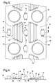
- Figure 3 is a top view of a partially fragmented fin; and
- Figure 4 is a cross-sectional view taken along line 4-4 of Figure 3.
-
- Referring to the Figures, wherein like numerals indicate like or corresponding parts throughout the several views, a heat exchanger is generally shown at 10 in Figure 1. The
heat exchanger 10 includes a pair ofmanifolds 12 and a plurality oftubes 14. Thetubes 14 are interconnected at opposite ends to themanifolds 12 to pass coolant between themanifolds 12. Theheat exchanger 10 also includes a plurality offins 16 disposed adjacent to each other. The plurality oftubes 14 pass through the plurality offins 16 for interconnecting thefins 16 together and mounting thefins 16 to theheat exchanger 10. In particular, thefins 16 definecollars 18 with thetubes 14 being received within and fixedly secured to thecollars 18. This general configuration of a heat exchanger defines what is known in the art as a fin-and-tube type heat exchanger. It should be appreciated that the exact configuration of themanifolds 12,tubes 14, andfins 16, could be of any suitable design without deviating from the scope of the subject invention. - The plurality of
fins 16 are disposed adjacent to each other with each of thefins 16 defining a plane and having anupstream portion 20 and adownstream portion 22. Theupstream portions 20 of the plurality of interconnectedfins 16 define anincoming airflow side 24 of theheat exchanger 10. Similarly, thedownstream portions 22 of the plurality of interconnectedfins 16 define anoutgoing airflow side 26 of theheat exchanger 10. As shown in Figure 1, theupstream portions 20 of thefins 16, as well as theincoming airflow side 24 of theheat exchanger 10, are orientated to face an incoming air flow. Each of thefins 16 also includes a firstouter surface 28 and a secondouter surface 30.Spacers 32 are preferably mounted to each of thefins 16 for maintaining proper distances betweenadjacent fins 16. Even more preferably, thespacers 32 extend outwardly from the firstouter surface 28 and are integrally formed within thefins 16. It should be appreciated that the spacers could be eliminated without deviating from the scope of the subject invention. - Referring also to Figures 2-4, the
fins 16 will now be discussed in greater detail. A plurality oflouvers 34 are formed in each of thefins 16 with eachlouver 34 extending at an angle with respect to the planes of thefins 16. The plurality oflouvers 34 define a first bank oflouvers 36 formed in each of theupstream portions 20 of thefins 16 facing theincoming airflow side 24 of theheat exchanger 10. The plurality oflouvers 34 also define a second bank oflouvers 38 formed in each of thedownstream portions 22 of thefms 16 facing theincoming airflow side 24 of theheat exchanger 10. Hence, all of thelouvers 34 are facing the same direction toward theincoming airflow side 24. In particular, each of thelouvers 34 includes a leadingedge 40 and atrailing edge 42 with the leadingedge 40 facing theincoming airflow side 24 of theheat exchanger 10. Thelouvers 34 are designed to effectively redirect and mix an incoming flow of air to increase a heat transfer between the surfaces of the heat exchanger, such as the surfaces of the fins and outer surface of the tubes, and the air flow. The unique configuration of thelouvers 34 also minimizes an air pressure drop across thefins 16 for optimizing the heat transfer between the tubes, fins and the air flow. - The preferred embodiment of the
louvers 34 is now discussed in detail. It should be appreciated that one or more of the specific features subsequently discussed could be altered or eliminated without deviating from the overall scope of the subject invention. In particular, thelouvers 34 of the first bank oflouvers 36 are preferably arranged in parallel with each other. Similarly, thelouvers 34 of the second bank oflouvers 38 are preferably arranged in parallel with each other. Each of thelouvers 34 also extend at a common angle with respect to the planes of thefins 16. In particular, the leadingedges 40 of thelouvers 34 extend a common distance from the corresponding plane of thecorresponding fin 16. Specifically, each of thelouvers 34 extends outwardly from only the firstouter surface 28 such that thelouvers 34 all extend in a common direction. - The first 36 and second 38 banks of louvers are designed to provide a grouping or series of
louvers 34 located in a particular location in thefins 16. The banks oflouvers trailing edge 42 of afirst louver 34 being adjacent to a leadingedge 40 of a secondsubsequent louver 34. Thetrailing edge 42 of thesecond louver 34 is in turn adjacent a leadingedge 40 of a thirdsubsequent louver 34 and so on until thefinal louver 34. The first 36 and second 38 banks of louvers are disposed between successive rows oftubes 14. The first 36 and second 38 banks of louvers also have a wedge shaped configuration with each of thelouvers 34 of thefirst bank 36 having a different length from each other and each of thelouvers 34 of thesecond bank 38 likewise having a different length from each other. Preferably, each of thelouvers 34 also have a common width which further defines the common angle and outward distance from the plane of thefins 16. The length of eachlouver 34 is defined as the dimension between the two ends where thelouver 34 is connected to thefin 16. The width of thelouver 34 is defined as the dimension between the leading 40 and trailing 42 edges in the direction of airflow. - In the most preferred embodiment, the plurality of
louvers 34 consist of a plurality of first 36 and second 38 banks of louvers. In other words, theonly louvers 34 on thefins 16 are associated with the first 36 and second 38 banks of louvers. As illustrated, the first 36 and second 38 banks of louvers are orientated in a pair of columns. The columns have alternatingtubes 14 and banks oflouvers additional louvers 34 may alternatively be included on thefins 16, it is important that all of thelouvers 34 face the same direction toward theincoming airflow side 24 of theheat exchanger 10. Further, the basic idea of the most preferred embodiment can be extended to fins that are deeper in the air flow direction. For example, there could be four rows oftubes 14 with four banks of louvers, etc. Also, while the most preferred embodiment shows the leadingedges 40 of thelouvers 34 extending a common distance from the plane of thefin 16, it is also possible for these distances to vary so long as the angle of all thelouvers 34 is common. Additionally, thelouvers 34 could also extend from bothouter surfaces fin 16 as long as the angle of all thelouvers 34 is common. - The invention has been described in an illustrative manner, and it is to be understood that the terminology which has been used is intended to be in the nature of words of description rather than of limitation. As is now apparent to those skilled in the art, many modifications and variations of the present invention are possible in light of the above teachings. It is, therefore, to be understood that within the scope of the appended claims, wherein reference numerals are merely for convenience and are not to be in any way limiting, the invention may be practiced otherwise than as specifically described.
Claims (15)
- A fin-and-tube type heat exchanger (10) comprising:a plurality of fins (16) disposed adjacent to each other with each of said fins (16) defining a plane and having an upstream portion (20) and a downstream portion (22);a plurality of louvers (34) formed in each of said fins (16) with each louver (34) extending at an angle with respect to said planes of said fins (16);a plurality of tubes (14) passing through said plurality of fins (16) interconnecting said fins 16 wherein said upstream portions (20) of said plurality of interconnected fins (16) define an incoming airflow side (24) of said heat exchanger (10) and said downstream portions (22) of said plurality of interconnected fins (16) define an outgoing airflow side (26) of said heat exchanger (10); andsaid plurality of louvers (34) defining a first bank of louvers (36) formed in each of said upstream portions (20) of said fins (16) facing said incoming airflow side (24) of said heat exchanger (10) and a second bank of louvers (38) formed in each of said downstream portions (22) of said fins (16) facing said incoming airflow side (24) of said heat exchanger (10) such that all of said louvers (34) are facing the same direction toward said incoming airflow side (24) whereby said louvers (34) effectively redirect and mix an incoming flow of air and minimize an air pressure drop across said fins (16) for increasing a heat transfer between said tubes (14), said fins (16), and the flow of air.
- A heat exchanger as set forth in claim 1 wherein said louvers (34) of said first bank of louvers (36) are arranged in parallel with each other.
- A heat exchanger as set forth in claim 2 wherein said louvers (34) of said second bank of louvers (38) are arranged in parallel with each other.
- A heat exchanger as set forth in claim 1 wherein said plurality of louvers (34) consist of a plurality of first (36) and second (38) banks of louvers.
- A heat exchanger as set forth in claim 1 wherein each of said louvers (34) extend at a common angle with respect to said planes of said fins (16).
- A heat exchanger as set forth in claim 1 wherein each of said louvers (34) includes a leading edge (40) and a trailing edge (42) with said leading edge (40) facing said incoming airflow side (24) of said heat exchanger (10).
- A heat exchanger as set forth in claim 6 wherein said leading edges (40) of said louvers (34) extend a common distance from said plane of said fin (16).
- A heat exchanger as set forth in claim 6 wherein said trailing edge (42) of a first louver (34) is adjacent to a leading edge (40) of a second subsequent louver (34) in each of said first (36) and second (38) banks of louvers.
- A heat exchanger as set forth in claim 1 wherein each of said fins (16) includes a first outer surface (28) and a second outer surface (30) with each of said louvers (34) extending outwardly from only said first outer surface (28) such that said louvers (34) all extend in a common direction.
- A heat exchanger as set forth in claim 1 wherein each of said louvers (34) has a common width.
- A heat exchanger as set forth in claim 10 wherein each of said louvers (34) of said first bank (36) have a different length from each other.
- A heat exchanger as set forth in claim 10 wherein each of said louvers (34) of said second bank (38) have a different length from each other.
- A heat exchanger as set forth in claim 1 wherein said fins (16) further define collars (18) with said tubes (14) being received within and fixedly mounted to said collars (18).
- A heat exchanger as set forth in claim 1 further including spacers (32) mounted to each of said fins (16) for maintaining proper distances between adjacent fins (16).
- A heat exchanger as set forth in claim 14 wherein said spacers (32) are integrally formed within said fins (16).
Applications Claiming Priority (2)
| Application Number | Priority Date | Filing Date | Title |
|---|---|---|---|
| US626029 | 2003-07-24 | ||
| US10/626,029 US7021370B2 (en) | 2003-07-24 | 2003-07-24 | Fin-and-tube type heat exchanger |
Publications (2)
| Publication Number | Publication Date |
|---|---|
| EP1500894A2 true EP1500894A2 (en) | 2005-01-26 |
| EP1500894A3 EP1500894A3 (en) | 2012-12-05 |
Family
ID=33490893
Family Applications (1)
| Application Number | Title | Priority Date | Filing Date |
|---|---|---|---|
| EP04077006A Withdrawn EP1500894A3 (en) | 2003-07-24 | 2004-07-09 | Fin-and-tube type heat exchanger |
Country Status (2)
| Country | Link |
|---|---|
| US (1) | US7021370B2 (en) |
| EP (1) | EP1500894A3 (en) |
Cited By (2)
| Publication number | Priority date | Publication date | Assignee | Title |
|---|---|---|---|---|
| EP2119995A4 (en) * | 2007-03-07 | 2014-05-14 | Daikin Ind Ltd | HEAT EXCHANGER |
| FR3038976A1 (en) * | 2015-07-17 | 2017-01-20 | Valeo Systemes Thermiques | HEAT EXCHANGER WITH FINS COMPRISING IMPROVED PERSIANS |
Families Citing this family (36)
| Publication number | Priority date | Publication date | Assignee | Title |
|---|---|---|---|---|
| US7428920B2 (en) * | 2003-08-21 | 2008-09-30 | Visteon Global Technologies, Inc. | Fin for heat exchanger |
| US10415894B2 (en) * | 2006-01-26 | 2019-09-17 | Ingersoll-Rand Company | Fin and tube heat exchanger |
| USD566824S1 (en) * | 2006-03-20 | 2008-04-15 | Ishikawajima-Harima Heavy Industries Co., Ltd. | Plate fin for a heat exchanger |
| US20070240865A1 (en) * | 2006-04-13 | 2007-10-18 | Zhang Chao A | High performance louvered fin for heat exchanger |
| US20070240868A1 (en) * | 2006-04-17 | 2007-10-18 | Chaun-Choung Technology Corp. | Air-guiding structure for heat-dissipating fin |
| US7568518B2 (en) * | 2006-07-21 | 2009-08-04 | Furui Precise Component (Kunshan) Co., Ltd. | Heat sink |
| US20080017350A1 (en) * | 2006-07-21 | 2008-01-24 | Foxconn Technology Co., Ltd. | Heat sink |
| WO2008064251A2 (en) | 2006-11-22 | 2008-05-29 | Johnson Controls Technology Company | Space-saving multichannel heat exchanger |
| WO2008064247A1 (en) * | 2006-11-22 | 2008-05-29 | Johnson Controls Technology Company | Multi-function multichannel heat exchanger |
| WO2008064219A1 (en) * | 2006-11-22 | 2008-05-29 | Johnson Controls Technology Company | Multichannel evaporator with flow mixing manifold |
| JP4293252B2 (en) * | 2007-03-19 | 2009-07-08 | ダイキン工業株式会社 | Fin for heat exchanger, guide and method of using the same |
| US20090025405A1 (en) * | 2007-07-27 | 2009-01-29 | Johnson Controls Technology Company | Economized Vapor Compression Circuit |
| US8166776B2 (en) * | 2007-07-27 | 2012-05-01 | Johnson Controls Technology Company | Multichannel heat exchanger |
| CN101370371B (en) * | 2007-08-17 | 2011-06-08 | 富准精密工业(深圳)有限公司 | Heat radiation model set and radiator used for the same |
| EP2193315B1 (en) * | 2007-08-24 | 2011-10-12 | Johnson Controls Technology Company | A vapor compression system and method of controlling it |
| US20100006276A1 (en) * | 2008-07-11 | 2010-01-14 | Johnson Controls Technology Company | Multichannel Heat Exchanger |
| US8234881B2 (en) | 2008-08-28 | 2012-08-07 | Johnson Controls Technology Company | Multichannel heat exchanger with dissimilar flow |
| CN102472599B (en) * | 2009-09-16 | 2014-02-19 | 松下电器产业株式会社 | Fin tube heat exchanger |
| US8439104B2 (en) * | 2009-10-16 | 2013-05-14 | Johnson Controls Technology Company | Multichannel heat exchanger with improved flow distribution |
| DE102010038945A1 (en) * | 2010-08-05 | 2012-02-09 | Behr Gmbh & Co. Kg | Plate-shaped heat exchanger for a, at least one heat exchanger package having cooling device |
| US20130299153A1 (en) * | 2011-01-21 | 2013-11-14 | Daikin Industries, Ltd. | Heat exchanger and air conditioner |
| CN103403487B (en) * | 2011-01-21 | 2015-11-25 | 大金工业株式会社 | Heat exchanger and air conditioner |
| US20130098590A1 (en) * | 2011-10-21 | 2013-04-25 | Mikutay Corporation | Heat Exchanger with heat exchange chambers and plate members utilizing respective medium directing members and method of making same |
| KR20140017835A (en) * | 2012-08-01 | 2014-02-12 | 엘지전자 주식회사 | A heat exchanger |
| KR101882020B1 (en) * | 2012-08-01 | 2018-07-25 | 엘지전자 주식회사 | A heat exchanger |
| USD776801S1 (en) * | 2014-06-24 | 2017-01-17 | Kobe Steel, Ltd | Heat exchanger tube |
| FR3038977B1 (en) * | 2015-07-17 | 2019-08-30 | Valeo Systemes Thermiques | HEAT EXCHANGER WITH FINS COMPRISING IMPROVED PERSIANS |
| CN205352165U (en) * | 2015-12-16 | 2016-06-29 | 杭州三花微通道换热器有限公司 | Heat exchanger core and heat exchanger that has it |
| US10208714B2 (en) | 2016-03-31 | 2019-02-19 | Mikutay Corporation | Heat exchanger utilized as an EGR cooler in a gas recirculation system |
| CN110741217B (en) * | 2017-06-12 | 2021-11-09 | 株式会社电装 | Heat exchanger and corrugated fin |
| US11774187B2 (en) * | 2018-04-19 | 2023-10-03 | Kyungdong Navien Co., Ltd. | Heat transfer fin of fin-tube type heat exchanger |
| KR102137462B1 (en) * | 2018-06-20 | 2020-07-24 | 엘지전자 주식회사 | Outdoor unit of air conditioner |
| JP2020063883A (en) * | 2018-10-18 | 2020-04-23 | 三星電子株式会社Samsung Electronics Co.,Ltd. | Heat exchanger and air conditioner |
| TWI736460B (en) * | 2020-10-30 | 2021-08-11 | 華擎科技股份有限公司 | Heat dissipation fin and heat dissipation module |
| JP7464872B1 (en) * | 2022-09-30 | 2024-04-10 | ダイキン工業株式会社 | Heat exchanger |
| CN223192187U (en) * | 2024-03-27 | 2025-08-05 | 杭州三花微通道换热器有限公司 | Fin, heat exchanger having the same, and heat exchange system |
Citations (5)
| Publication number | Priority date | Publication date | Assignee | Title |
|---|---|---|---|---|
| US4434844A (en) | 1981-05-15 | 1984-03-06 | Daikin Kogyo Co., Ltd. | Cross-fin coil type heat exchanger |
| US4550776A (en) | 1983-05-24 | 1985-11-05 | Lu James W B | Inclined radially louvered fin heat exchanger |
| US5099914A (en) | 1989-12-08 | 1992-03-31 | Nordyne, Inc. | Louvered heat exchanger fin stock |
| US5509469A (en) | 1994-04-19 | 1996-04-23 | Inter-City Products Corporation (Usa) | Interrupted fin for heat exchanger |
| US5730214A (en) | 1997-01-16 | 1998-03-24 | General Motors Corporation | Heat exchanger cooling fin with varying louver angle |
Family Cites Families (17)
| Publication number | Priority date | Publication date | Assignee | Title |
|---|---|---|---|---|
| HU181538B (en) * | 1980-03-11 | 1983-10-28 | Energiagazdalkodasi Intezet | Turbulent heat exchanger |
| JPS58158495A (en) * | 1982-03-16 | 1983-09-20 | Matsushita Electric Ind Co Ltd | Tube heat exchanger with fins |
| JPH0610591B2 (en) * | 1983-07-29 | 1994-02-09 | 三菱電機株式会社 | Heat exchanger |
| JPS616591A (en) * | 1984-06-19 | 1986-01-13 | Matsushita Refrig Co | Finned heat exchanger |
| KR890002903B1 (en) * | 1984-09-04 | 1989-08-08 | 마쯔시다덴기산교 가부시기가이샤 | heat transmitter |
| CA1270811A (en) * | 1985-05-10 | 1990-06-26 | Shoichi Yokoyama | Heat exchanger |
| JPS62175590A (en) * | 1986-01-27 | 1987-08-01 | Matsushita Refrig Co | Finch tube heat exchanger |
| JPS62194194A (en) * | 1986-02-20 | 1987-08-26 | Fujitsu General Ltd | Heat exchanger |
| US4709753A (en) * | 1986-09-08 | 1987-12-01 | Nordyne, Inc. | Uni-directional fin-and-tube heat exchanger |
| US4738225A (en) * | 1987-06-03 | 1988-04-19 | Juang Jinn C | Heat transfer apparatus for water heater |
| JP2834339B2 (en) * | 1991-02-21 | 1998-12-09 | 松下電器産業株式会社 | Finned heat exchanger |
| KR0155654B1 (en) * | 1995-01-23 | 1999-01-15 | 이헌조 | Fin & tube type heat exchanger |
| JPH09133488A (en) * | 1995-11-09 | 1997-05-20 | Matsushita Electric Ind Co Ltd | Finned heat exchanger |
| KR100197718B1 (en) * | 1996-12-30 | 1999-06-15 | 윤종용 | Heat exchanger of air conditioner |
| US5975200A (en) * | 1997-04-23 | 1999-11-02 | Denso Corporation | Plate-fin type heat exchanger |
| KR100347944B1 (en) * | 1999-06-03 | 2002-08-09 | 엘지전자주식회사 | Fin of evaporator in air conditioner |
| JP2003156295A (en) * | 2001-11-19 | 2003-05-30 | Matsushita Electric Ind Co Ltd | Finned heat exchanger |
-
2003
- 2003-07-24 US US10/626,029 patent/US7021370B2/en not_active Expired - Lifetime
-
2004
- 2004-07-09 EP EP04077006A patent/EP1500894A3/en not_active Withdrawn
Patent Citations (5)
| Publication number | Priority date | Publication date | Assignee | Title |
|---|---|---|---|---|
| US4434844A (en) | 1981-05-15 | 1984-03-06 | Daikin Kogyo Co., Ltd. | Cross-fin coil type heat exchanger |
| US4550776A (en) | 1983-05-24 | 1985-11-05 | Lu James W B | Inclined radially louvered fin heat exchanger |
| US5099914A (en) | 1989-12-08 | 1992-03-31 | Nordyne, Inc. | Louvered heat exchanger fin stock |
| US5509469A (en) | 1994-04-19 | 1996-04-23 | Inter-City Products Corporation (Usa) | Interrupted fin for heat exchanger |
| US5730214A (en) | 1997-01-16 | 1998-03-24 | General Motors Corporation | Heat exchanger cooling fin with varying louver angle |
Cited By (4)
| Publication number | Priority date | Publication date | Assignee | Title |
|---|---|---|---|---|
| EP2119995A4 (en) * | 2007-03-07 | 2014-05-14 | Daikin Ind Ltd | HEAT EXCHANGER |
| FR3038976A1 (en) * | 2015-07-17 | 2017-01-20 | Valeo Systemes Thermiques | HEAT EXCHANGER WITH FINS COMPRISING IMPROVED PERSIANS |
| WO2017012868A1 (en) * | 2015-07-17 | 2017-01-26 | Valeo Systemes Thermiques | Fin heat exchanger comprising improved louvres |
| CN108431537A (en) * | 2015-07-17 | 2018-08-21 | 法雷奥热系统公司 | Include the fin heat exchanger of improved louvre blade |
Also Published As
| Publication number | Publication date |
|---|---|
| US20050016718A1 (en) | 2005-01-27 |
| EP1500894A3 (en) | 2012-12-05 |
| US7021370B2 (en) | 2006-04-04 |
Similar Documents
| Publication | Publication Date | Title |
|---|---|---|
| US7021370B2 (en) | Fin-and-tube type heat exchanger | |
| JP4674602B2 (en) | Heat exchanger | |
| EP2141435B1 (en) | Plate fin tube-type heat exchanger | |
| EP2314972B1 (en) | Heat exchanger | |
| US5062475A (en) | Chevron lanced fin design with unequal leg lengths for a heat exchanger | |
| JP2960883B2 (en) | Fin tube type heat exchanger | |
| CN102128555A (en) | Fin for heat exchanger and heat exchanger having the same | |
| US20130199760A1 (en) | Heat exchanger assembly having split mini-louvered fins | |
| JPH0210097A (en) | Heat exchanger | |
| JP2002062076A (en) | Small diametric tube type heat exchanger | |
| KR100740180B1 (en) | Finned heat exchanger and method of manufacturing the same | |
| US4709753A (en) | Uni-directional fin-and-tube heat exchanger | |
| US20090173479A1 (en) | Louvered air center for compact heat exchanger | |
| WO2007089619A2 (en) | Fin and tube heat exchanger | |
| US5975200A (en) | Plate-fin type heat exchanger | |
| JPS60194293A (en) | Heat exchanger equipped with fin | |
| US5947194A (en) | Heat exchanger fins of an air conditioner | |
| US5611395A (en) | Fin for heat exchanger | |
| JP3446427B2 (en) | Heat exchanger | |
| JP2000154989A (en) | Air heat exchanger | |
| JP4513207B2 (en) | Air heat exchanger | |
| JPS62147290A (en) | Heat exchanger | |
| US20030094267A1 (en) | Multi-edge folded louvered fin for heat exchanger | |
| JPH10332292A (en) | Heat-exchanger | |
| JPH0645183Y2 (en) | Heat exchanger fins |
Legal Events
| Date | Code | Title | Description |
|---|---|---|---|
| PUAI | Public reference made under article 153(3) epc to a published international application that has entered the european phase |
Free format text: ORIGINAL CODE: 0009012 |
|
| AK | Designated contracting states |
Kind code of ref document: A2 Designated state(s): AT BE BG CH CY CZ DE DK EE ES FI FR GB GR HU IE IT LI LU MC NL PL PT RO SE SI SK TR |
|
| AX | Request for extension of the european patent |
Extension state: AL HR LT LV MK |
|
| PUAL | Search report despatched |
Free format text: ORIGINAL CODE: 0009013 |
|
| AK | Designated contracting states |
Kind code of ref document: A3 Designated state(s): AT BE BG CH CY CZ DE DK EE ES FI FR GB GR HU IE IT LI LU MC NL PL PT RO SE SI SK TR |
|
| AX | Request for extension of the european patent |
Extension state: AL HR LT LV MK |
|
| RIC1 | Information provided on ipc code assigned before grant |
Ipc: F28F 1/32 20060101AFI20121031BHEP |
|
| AKY | No designation fees paid | ||
| REG | Reference to a national code |
Ref country code: DE Ref legal event code: R108 Effective date: 20130814 |
|
| STAA | Information on the status of an ep patent application or granted ep patent |
Free format text: STATUS: THE APPLICATION IS DEEMED TO BE WITHDRAWN |
|
| 18D | Application deemed to be withdrawn |
Effective date: 20130606 |