EP1500882A2 - Outdoor unit for use in air conditioner - Google Patents
Outdoor unit for use in air conditioner Download PDFInfo
- Publication number
- EP1500882A2 EP1500882A2 EP04016998A EP04016998A EP1500882A2 EP 1500882 A2 EP1500882 A2 EP 1500882A2 EP 04016998 A EP04016998 A EP 04016998A EP 04016998 A EP04016998 A EP 04016998A EP 1500882 A2 EP1500882 A2 EP 1500882A2
- Authority
- EP
- European Patent Office
- Prior art keywords
- unit
- electronic module
- outdoor
- outdoor unit
- main body
- Prior art date
- Legal status (The legal status is an assumption and is not a legal conclusion. Google has not performed a legal analysis and makes no representation as to the accuracy of the status listed.)
- Granted
Links
Images


Classifications
-
- F—MECHANICAL ENGINEERING; LIGHTING; HEATING; WEAPONS; BLASTING
- F24—HEATING; RANGES; VENTILATING
- F24F—AIR-CONDITIONING; AIR-HUMIDIFICATION; VENTILATION; USE OF AIR CURRENTS FOR SCREENING
- F24F1/00—Room units for air-conditioning, e.g. separate or self-contained units or units receiving primary air from a central station
- F24F1/06—Separate outdoor units, e.g. outdoor unit to be linked to a separate room comprising a compressor and a heat exchanger
- F24F1/20—Electric components for separate outdoor units
-
- F—MECHANICAL ENGINEERING; LIGHTING; HEATING; WEAPONS; BLASTING
- F24—HEATING; RANGES; VENTILATING
- F24F—AIR-CONDITIONING; AIR-HUMIDIFICATION; VENTILATION; USE OF AIR CURRENTS FOR SCREENING
- F24F1/00—Room units for air-conditioning, e.g. separate or self-contained units or units receiving primary air from a central station
- F24F1/06—Separate outdoor units, e.g. outdoor unit to be linked to a separate room comprising a compressor and a heat exchanger
- F24F1/20—Electric components for separate outdoor units
- F24F1/22—Arrangement or mounting thereof
-
- F—MECHANICAL ENGINEERING; LIGHTING; HEATING; WEAPONS; BLASTING
- F24—HEATING; RANGES; VENTILATING
- F24F—AIR-CONDITIONING; AIR-HUMIDIFICATION; VENTILATION; USE OF AIR CURRENTS FOR SCREENING
- F24F13/00—Details common to, or for air-conditioning, air-humidification, ventilation or use of air currents for screening
- F24F13/20—Casings or covers
- F24F2013/207—Casings or covers with control knobs; Mounting controlling members or control units therein
Definitions
- the present invention relates to an air conditioner; and, more particularly to an outdoor unit of a split type air conditioner.
- the compressor and a control unit for controlling the compressor are installed in an outdoor unit of the air conditioner to operate a cooling cycle.
- outdoor unit main body 100 includes at least compressor 110 having a compressor unit and a motor unit for driving the compressor unit, both of which are incorporated in a sealed vessel; outdoor radiator 120 for performing a heat exchange with the ambient air; and blower 130 for blowing the ambient air through the outdoor unit 100 for a heat exchange. All of these components, i.e., compressor 110, outdoor radiator 120 and blower 130 are incorporated in an outer frame body (not shown). Further, provided in an upper space of outdoor unit 100 is driving circuit unit 140 for driving the components of outdoor unit 100.
- Driving circuit unit 140 includes a compressor control unit for controlling compressor 110, a blower control unit for controlling blower 130, cooling cycle control unit for controlling the cooling cycle, a wiring unit coupled to an indoor unit, and so forth. Among these components, the compressor control unit occupies most space of driving circuit unit 140.
- the driving circuit for driving compressor 110 through an inverter control includes a converter circuit unit for converting a commercial AC power source into a DC; an inverter circuit unit for driving the motor unit of compressor 110 by way of converting the DC into a three-phase AC; a control circuit unit for controlling the converter circuit and the inverter circuit; and so forth.
- control unit occupies a great volume of the outdoor unit, whereby a effective heat transfer area of the outdoor radiator is reduced, resulting in a deterioration of efficiency of the air conditioner.
- an object of the present invention to provide an air conditioner including an outdoor unit with a reduced size and an increased effective heat transfer area of a radiator by way of efficiently disposing a scaled-down motor control unit, which is inverter-controlled by using a commercial AC power source, in the outdoor unit.
- an outdoor unit of an air conditioner including: a unit main body; an outdoor radiator; an outdoor blower; a compressor for compressing a coolant; and an electronic module including circuit components incorporated in a sealed housing, wherein the circuit components have at least a converter circuit unit for driving the compressor, an inverter circuit unit and a control circuit unit.
- the electronic module operated by an inverter control using a commercial AC power source can be integrated within a housing to obtain a compact size and a water drip-proof structure. Further, since the electronic module can be independently disposed at any desired place within the outdoor unit, efficient use of the inner space of the outdoor unit is enabled and an effective heat transfer area of the outdoor radiator can be increased, thereby enhancing air conditioning efficiency.
- the electronic module is disposed in an airflow path formed by the outdoor blower. Therefore, the electronic module can be efficiently cooled, thereby improving reliability of the circuit components within the electronic module.
- the unit main body has a bottom plate, and the electronic module is mounted on the bottom plate.
- the bottom plate can be utilized as a heat radiation plate of exothermic circuit elements within the electronic module, thereby further improving the reliability of the circuit components.
- the electronic module is mounted on the bottom plate to be located below the compressor.
- the electronic module is disposed in a dead water region of an airflow path formed by the outdoor blower. Therefore, efficient use of the inner space of the outdoor unit is enabled and a size-reduction of the outdoor unit can be achieved without deteriorating heat transfer efficiency.
- the airflow path is formed by the outdoor blower with a bell mouth portion at least serving as an air guide, and the electronic module is installed at a peripheral portion of the bell mouth portion. Resultantly, efficient use of the inner space of the outdoor unit is enabled.
- the outdoor blower includes a fan unit and a fan motor for driving the fan unit, and the electronic module is disposed at a rear side of the fan motor. Therefore, efficient use of the inner space of the outdoor unit is enabled, and a size reduction thereof can be achieved.
- the electronic module includes a power supply terminal and the unit main body includes a side plate, wherein the electronic module is disposed on the side plate and the power supply terminal is disposed to be exposed to the outside of the outdoor unit. Accordingly, it becomes possible to use the side plate as a heat radiation plate of exothermic elements within the electronic module, which in turn enhances reliability of the circuit components. In addition, a connection of the power supply terminal to the outside gets easier.
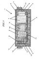
- FIG. 1 there is provided a cross sectional view of an electronic module in accordance with a first preferred embodiment of the present invention.
- Electronic module main body 1 includes housing 5 formed by side plates 2, bottom plate 3 and ceiling plate 4.
- housing 5 is a plurality of circuit components for driving a compressor.
- the circuit components are accommodated by being grouped into three blocks: a converter circuit unit for converting a commercial AC power source into a DC, an inverter circuit unit for inverting a DC into an AC, and a control circuit unit.
- Side plates 2, ceiling plate 4 and bottom plate 4 of housing 5 are made of, e.g., a metallic material having a high heat conductivity, and build up a water drip-proof structure.
- diode 6 and circuit components 7 such as a capacitor and an inductor.
- IGBT Insulated Gate Bipolar Transistor
- control circuit components such as a control signal generator and a microcomputer.
- power supply terminal 11 of a commercial AC power source and output terminal 12 for supplying the power to the compressor.
- circuit components diode 6, circuit component 7, IGBT device 8, driving circuit 9 and control circuit component 10.
- Exothermic circuit elements such as diode 6 of the converter circuit unit and IGBT device 8 of the inverter circuit unit are located to face side plates 2, and thermal conductors 14 made of a material with a high heat conductivity are intervened between side plates 2 and the exothermic circuit elements. Thermal conductors 14 serve to emit the heat generated from diode 6 and IGBT device 8 to the outside.
- adhesive resin layer 15 may be disposed closely adhered to the exothermic circuit elements, e.g., the IGBT device 8.
- resin 16 is charged between the circuit components within housing 5, thereby insulating the circuit components (diode 6, circuit component 7, IGBT device 8, driving circuit 9, and control circuit component 10) from each other and, at the same time, obtaining vibration resistance and moisture resistance.
- electronic module main body 1 has the water drip-proof structure by forming housing 5 as a sealed one body, reliability of the circuit components within electronic module main body 1 can be improved. Moreover, since the circuit components disposed in housing 5 are protected by resin 16 charged therebetween, insulating property and vibration resistance can be obtained. Therefore, it becomes possible to secure the reliability of the circuit components even in case they are directly mounted on a vibration-generating source such as a compressor.
- electronic module main body 1 can be of any shape, e.g., a cylindrical shape or a rectangular parellelopiped shape, depending on its location in an outdoor unit.
- Outdoor unit main body 30 includes casing 31, outdoor radiator 32, outdoor blower 32, and compressor 34.
- Casing 31 is of a box shape formed by bottom plate 35, left and right side plates 36, front plate 37, rear plate 38 and ceiling plate 39.
- Outdoor blower 33 has fan unit 40 and fan motor 41 for driving fan unit 40.
- bell mouth 42 serving as an air-guiding opening.
- Outdoor radiator 32 is installed in an L shape along left side plate 36 and rear plate 38, as show in Fig. 2A to obtain a predetermined heat transfer area. Further, compressor 34 is isolated from the airflow path by cover 43.
- electronic module main body 1 shown in Fig. 1 for driving at least compressor 34 is mounted on bottom plate 35 of casing 31 as shown in Figs. 2A and 2B. Since reduction in the size of electronic module main body 1 can be readily achieved as described in Fig. 1, it can be disposed at any available position on bottom plate 35. Further, though the exothermic elements such as diode 6 of the converter circuit unit and IGBT device 8 of the inverter circuit unit are disposed to face side plates 2 in electronic module main body 1 shown in Fig. 1, the first preferred embodiment employs a configuration where the exothermic elements are mounted on bottom plate 3 of electronic module main body 1, which is in turn disposed on bottom plate 35 of casing 31.
- bottom plate 35 with a large radiation area as a heat radiation plate of the exothermic elements in electronic module main body 1. Further, since the vicinity of bottom plate 35 of casing 31 forms the airflow path described above, electronic module main body 1 may be forcibly cooled down by the wind in the airflow path. As a result, the inner space of outdoor unit main body 30 can be efficiently utilized while improving the reliability of the circuit components.
- parts other than electronic module main body 1 for driving compressor 34 e.g., electrical component for driving fan motor 41
- electrical component 44 may be disposed at their conventional positions with further reduced sizes
- the conventional problem that electrical component 44 reduces the effective heat transfer area of outdoor radiator 32 can be solved, thereby improving a radiation performance thereof and enhancing the efficiency of the air conditioner.
- Figs. 3A and 3B illustrate a plan and a front view of an outdoor unit of another air conditioner in accordance with the first preferred embodiment of the present invention.
- electronic module main body 1 is mounted on bottom plate 35 of casing 31 of outdoor unit main body 30, and compressor 34 is disposed on electronic module main body 1.
- compressor 34 can be integrated as one body with electronic module main body 1, assembling outdoor unit main body 30 may become easier and more efficient. Furthermore, the integration of compressor 34 and electronic module main body 1 as one unit also eases the maintenance thereof.
- FIGs. 4A and 4B there are illustrated a plan and a front view of an outdoor unit of an air conditioner in accordance with a second preferred embodiment of the present invention.
- the distinctiveness of the second preferred embodiment resides in that electronic module main body 1 is disposed in a dead water region of an airflow path within outdoor unit main body 1, the airflow path being formed by outdoor blower 33.
- the term 'dead water region' herein used refers to a region where a wind does not blow at all or hardly blows.
- electronic module main body 1 is disposed at a peripheral portion of bell mouth 42 which is provided at front plate 37 of casing 31 to serve as an air guide.
- the peripheral portion of bell mouth 42 which hardly involves a wind blow or features a very low wind velocity, forms a useless space in outdoor unit main body 30.
- since electronic module main body 1 is disposed in this space it is possible to efficiently use the inner space of outdoor unit main body 30, thereby realizing a size reduction thereof.
- an increase of an air flow resistance and a resultant increase of power consumption of fan motor 41 can be prevented.
- a high velocity air current is formed in a rotation region of fan unit 40, i.e., a peripheral portion of bell mouth 42. Accordingly, if a desired fin unit is installed at a part of housing 5 of electronic module main body 1 where the high velocity air current flows, it may serve to facilitate a radiation of exothermic circuit elements.
- a plan and a front view of an outdoor unit of another air conditioner in accordance with the second preferred embodiment.
- electronic module main body 1 is disposed at a rear plate 38 side of fan motor 41.
- the region around the rear plate 38 side of fan motor 41 is an area where a wind suctioned by fan unit 40 does not blow, forming a useless space in outdoor unit main body 30.
- electronic module main body 1 is disposed in this region, thereby enabling an efficient use of the inner space of outdoor unit main body 30 while realizing a size reduction thereof.
- a high velocity air current suctioned by fan unit 40 is formed around an outer peripheral portion of fan motor 41. Accordingly, if a desired fin unit is installed at a part of housing 5 of electronic module main body 1 in a manner that it corresponds to the high velocity current area, it may serve to facilitate a radiation of exothermic circuit elements.
- Figs. 6A and 6B describe a plan and a front view of an outdoor unit of an air conditioner in accordance with a third preferred embodiment of the present invention.
- electronic module main body 1 is mounted on side plate 36 of casing 31 of outdoor unit main body 30 to be located above compressor 34 with its power supply terminal 47 exposed to the outside. Accordingly, side plate 36 having a large area can be utilized as a heat radiation plate of exothermic circuit elements in electronic module main body 1. Furthermore, by disposing electronic module main body 1 near compressor 34, a wiring connection therebetween becomes easier. Still further, by way of installing power supply terminal 47 of electronic module main body 1 to be exposed to the outside, a connection between power supply terminal 30 and an external power source can be readily accomplished. Consequently, an efficient use of the inner space of outdoor unit main body 30 is enabled while improving reliability of circuit components.
- the outdoor unit can improve air conditioning efficiency. Therefore, the outdoor unit of the present invention can be used in various split type air conditioners for use in household and commercial environment.
Landscapes
- Engineering & Computer Science (AREA)
- Chemical & Material Sciences (AREA)
- Combustion & Propulsion (AREA)
- Mechanical Engineering (AREA)
- General Engineering & Computer Science (AREA)
- Other Air-Conditioning Systems (AREA)
Abstract
Description
Claims (8)
- An outdoor unit of an air conditioner, comprising:wherein the circuit components have at least a converter circuit unit for driving the compressor, an inverter circuit unit and a control circuit unit.a unit main body;an outdoor radiator;an outdoor blower;a compressor for compressing a coolant; andan electronic module including circuit components incorporated in a sealed housing,
- The outdoor unit of claim 1, wherein the electronic module is disposed in an airflow path formed by the outdoor blower.
- The outdoor unit of claim 1, wherein the unit main body has a bottom plate and the electronic module is mounted on the bottom plate.
- The outdoor unit of claim 3, wherein the compressor is located above the electronic module.
- The outdoor unit of claim 1, wherein the electronic module is disposed in a dead water region of an airflow path formed by the outdoor blower.
- The outdoor unit of claim 5, wherein the airflow path is formed by the outdoor blower with a bell mouth portion at least serving as an air guide, and the electronic module is installed at a peripheral portion of the bell mouth portion.
- The outdoor unit of claim 5, wherein the outdoor blower includes a fan unit and a fan motor for driving the fan unit, and the electronic module is disposed at a rear side of the fan motor.
- The outdoor unit of claim 1, wherein the unit main body has a side plate and the electronic module includes a power supply terminal, and wherein the electronic module is disposed on the side plate and the power supply terminal is disposed to face the outside of the outdoor unit.
Applications Claiming Priority (2)
| Application Number | Priority Date | Filing Date | Title |
|---|---|---|---|
| JP2003277431 | 2003-07-22 | ||
| JP2003277431 | 2003-07-22 |
Publications (3)
| Publication Number | Publication Date |
|---|---|
| EP1500882A2 true EP1500882A2 (en) | 2005-01-26 |
| EP1500882A3 EP1500882A3 (en) | 2006-08-16 |
| EP1500882B1 EP1500882B1 (en) | 2012-10-17 |
Family
ID=33487677
Family Applications (1)
| Application Number | Title | Priority Date | Filing Date |
|---|---|---|---|
| EP04016998A Expired - Lifetime EP1500882B1 (en) | 2003-07-22 | 2004-07-19 | Outdoor unit for use in air conditioner |
Country Status (3)
| Country | Link |
|---|---|
| EP (1) | EP1500882B1 (en) |
| CN (1) | CN1266423C (en) |
| ES (1) | ES2397008T3 (en) |
Cited By (6)
| Publication number | Priority date | Publication date | Assignee | Title |
|---|---|---|---|---|
| WO2006082779A1 (en) * | 2005-02-03 | 2006-08-10 | Daikin Industries, Ltd. | Outdoor unit of air conditioner |
| JP2006214633A (en) * | 2005-02-03 | 2006-08-17 | Daikin Ind Ltd | Air conditioner outdoor unit |
| JP2006214635A (en) * | 2005-02-03 | 2006-08-17 | Daikin Ind Ltd | Air conditioner outdoor unit |
| JP2006214632A (en) * | 2005-02-03 | 2006-08-17 | Daikin Ind Ltd | Air conditioner outdoor unit |
| CN101111719B (en) * | 2005-02-03 | 2010-10-06 | 大金工业株式会社 | Outdoor unit of air conditioning unit |
| US20150059389A1 (en) * | 2013-09-05 | 2015-03-05 | Trane International Inc. | System and apparatus for heating or cooling having fluid cooled electronics |
Families Citing this family (2)
| Publication number | Priority date | Publication date | Assignee | Title |
|---|---|---|---|---|
| WO2019106854A1 (en) * | 2017-11-28 | 2019-06-06 | シャープ株式会社 | Outdoor unit |
| US11371738B2 (en) | 2019-01-09 | 2022-06-28 | Johnson Controls Tyco IP Holdings LLP | Enclosure for a controller of an HVAC system |
Citations (2)
| Publication number | Priority date | Publication date | Assignee | Title |
|---|---|---|---|---|
| JP2000022209A (en) | 1998-06-30 | 2000-01-21 | Kyocera Corp | Semiconductor light emitting device |
| EP1416230A1 (en) | 2001-08-09 | 2004-05-06 | Toshiba Carrier Corporation | Outdoor unit of air conditioner |
Family Cites Families (5)
| Publication number | Priority date | Publication date | Assignee | Title |
|---|---|---|---|---|
| JPH02110227A (en) * | 1988-10-19 | 1990-04-23 | Matsushita Seiko Co Ltd | Air conditioner |
| US5294195A (en) * | 1992-11-02 | 1994-03-15 | Carrier Corporation | Cover for the outside enclosure of an air conditioning system |
| JP3322778B2 (en) * | 1995-08-22 | 2002-09-09 | 東芝キヤリア株式会社 | Outdoor unit of air conditioner |
| JP2003106573A (en) * | 2001-09-28 | 2003-04-09 | Matsushita Electric Ind Co Ltd | Electrical component storage box for separate type air conditioner outdoor unit |
| JP3858661B2 (en) * | 2001-10-10 | 2006-12-20 | ダイキン工業株式会社 | Electrical component box and air conditioner |
-
2004
- 2004-07-19 ES ES04016998T patent/ES2397008T3/en not_active Expired - Lifetime
- 2004-07-19 EP EP04016998A patent/EP1500882B1/en not_active Expired - Lifetime
- 2004-07-21 CN CN200410070973.9A patent/CN1266423C/en not_active Expired - Fee Related
Patent Citations (2)
| Publication number | Priority date | Publication date | Assignee | Title |
|---|---|---|---|---|
| JP2000022209A (en) | 1998-06-30 | 2000-01-21 | Kyocera Corp | Semiconductor light emitting device |
| EP1416230A1 (en) | 2001-08-09 | 2004-05-06 | Toshiba Carrier Corporation | Outdoor unit of air conditioner |
Cited By (6)
| Publication number | Priority date | Publication date | Assignee | Title |
|---|---|---|---|---|
| WO2006082779A1 (en) * | 2005-02-03 | 2006-08-10 | Daikin Industries, Ltd. | Outdoor unit of air conditioner |
| JP2006214633A (en) * | 2005-02-03 | 2006-08-17 | Daikin Ind Ltd | Air conditioner outdoor unit |
| JP2006214635A (en) * | 2005-02-03 | 2006-08-17 | Daikin Ind Ltd | Air conditioner outdoor unit |
| JP2006214632A (en) * | 2005-02-03 | 2006-08-17 | Daikin Ind Ltd | Air conditioner outdoor unit |
| CN101111719B (en) * | 2005-02-03 | 2010-10-06 | 大金工业株式会社 | Outdoor unit of air conditioning unit |
| US20150059389A1 (en) * | 2013-09-05 | 2015-03-05 | Trane International Inc. | System and apparatus for heating or cooling having fluid cooled electronics |
Also Published As
| Publication number | Publication date |
|---|---|
| ES2397008T3 (en) | 2013-03-04 |
| CN1576729A (en) | 2005-02-09 |
| EP1500882B1 (en) | 2012-10-17 |
| EP1500882A3 (en) | 2006-08-16 |
| CN1266423C (en) | 2006-07-26 |
Similar Documents
| Publication | Publication Date | Title |
|---|---|---|
| US7003970B2 (en) | Power module and air conditioner | |
| US6501662B2 (en) | Motor driving inverter | |
| CN101187364B (en) | Inverter-integrated electric compressor | |
| JP5529477B2 (en) | Inverter-integrated electric compressor | |
| JP4144465B2 (en) | Inverter-integrated electric compressor for vehicles | |
| JP2008121966A (en) | Air conditioner outdoor unit | |
| CN116232013B (en) | Inverter and electrical equipment | |
| EP1500882B1 (en) | Outdoor unit for use in air conditioner | |
| CN206037286U (en) | Outdoor unit of air conditioner | |
| JP2010187435A (en) | Power conversion device, motor with built-in drive circuit using the power conversion device, indoor unit of air conditioner using the motor with built-in drive circuit, air conditioner, ventilation fan, pump, and equipment and water heater using the pump | |
| CN217715407U (en) | Frequency conversion compressor drive cooling system | |
| CN100459394C (en) | Control unit and compressor used thereby | |
| JP5030551B2 (en) | Inverter-integrated electric compressor | |
| CN104620485B (en) | The convertor device of air conditioner | |
| CN114183904A (en) | Electrical box, air conditioner and control method | |
| JP2003139352A (en) | Electrical equipment unit for outdoor unit and outdoor unit for air conditioner | |
| JP2014093304A (en) | Power conversion device | |
| CN216384525U (en) | Electrical apparatus box and air conditioner | |
| JP2005055166A (en) | Air conditioner outdoor unit | |
| CN217721009U (en) | Electric control system device and electric equipment | |
| JPH11210640A (en) | Pump device | |
| JP2007250700A (en) | Semiconductor device | |
| CN222981869U (en) | High power inverter and inverter housing | |
| JPH08284831A (en) | Pump operation control panel and pump device using the same | |
| CN220507045U (en) | Electrical box cooling components and air conditioners |
Legal Events
| Date | Code | Title | Description |
|---|---|---|---|
| PUAI | Public reference made under article 153(3) epc to a published international application that has entered the european phase |
Free format text: ORIGINAL CODE: 0009012 |
|
| AK | Designated contracting states |
Kind code of ref document: A2 Designated state(s): AT BE BG CH CY CZ DE DK EE ES FI FR GB GR HU IE IT LI LU MC NL PL PT RO SE SI SK TR |
|
| AX | Request for extension of the european patent |
Extension state: AL HR LT LV MK |
|
| PUAL | Search report despatched |
Free format text: ORIGINAL CODE: 0009013 |
|
| AK | Designated contracting states |
Kind code of ref document: A3 Designated state(s): AT BE BG CH CY CZ DE DK EE ES FI FR GB GR HU IE IT LI LU MC NL PL PT RO SE SI SK TR |
|
| AX | Request for extension of the european patent |
Extension state: AL HR LT LV MK |
|
| 17P | Request for examination filed |
Effective date: 20070212 |
|
| AKX | Designation fees paid |
Designated state(s): ES GR IT |
|
| 17Q | First examination report despatched |
Effective date: 20070405 |
|
| REG | Reference to a national code |
Ref country code: DE Ref legal event code: 8566 |
|
| RAP1 | Party data changed (applicant data changed or rights of an application transferred) |
Owner name: PANASONIC CORPORATION |
|
| REG | Reference to a national code |
Ref country code: DE Ref legal event code: R079 Free format text: PREVIOUS MAIN CLASS: F24F0001000000 Ipc: F24F0001200000 |
|
| RIC1 | Information provided on ipc code assigned before grant |
Ipc: F24F 1/22 20110101ALI20120402BHEP Ipc: F24F 1/20 20110101AFI20120402BHEP |
|
| GRAP | Despatch of communication of intention to grant a patent |
Free format text: ORIGINAL CODE: EPIDOSNIGR1 |
|
| GRAS | Grant fee paid |
Free format text: ORIGINAL CODE: EPIDOSNIGR3 |
|
| GRAA | (expected) grant |
Free format text: ORIGINAL CODE: 0009210 |
|
| AK | Designated contracting states |
Kind code of ref document: B1 Designated state(s): ES GR IT |
|
| REG | Reference to a national code |
Ref country code: GR Ref legal event code: EP Ref document number: 20120402505 Country of ref document: GR Effective date: 20121122 |
|
| REG | Reference to a national code |
Ref country code: ES Ref legal event code: FG2A Ref document number: 2397008 Country of ref document: ES Kind code of ref document: T3 Effective date: 20130304 |
|
| PLBE | No opposition filed within time limit |
Free format text: ORIGINAL CODE: 0009261 |
|
| STAA | Information on the status of an ep patent application or granted ep patent |
Free format text: STATUS: NO OPPOSITION FILED WITHIN TIME LIMIT |
|
| 26N | No opposition filed |
Effective date: 20130718 |
|
| PGFP | Annual fee paid to national office [announced via postgrant information from national office to epo] |
Ref country code: ES Payment date: 20140611 Year of fee payment: 11 Ref country code: GR Payment date: 20140620 Year of fee payment: 11 |
|
| PGFP | Annual fee paid to national office [announced via postgrant information from national office to epo] |
Ref country code: IT Payment date: 20140714 Year of fee payment: 11 |
|
| PG25 | Lapsed in a contracting state [announced via postgrant information from national office to epo] |
Ref country code: IT Free format text: LAPSE BECAUSE OF NON-PAYMENT OF DUE FEES Effective date: 20150719 |
|
| PG25 | Lapsed in a contracting state [announced via postgrant information from national office to epo] |
Ref country code: GR Free format text: LAPSE BECAUSE OF NON-PAYMENT OF DUE FEES Effective date: 20160202 |
|
| REG | Reference to a national code |
Ref country code: GR Ref legal event code: ML Ref document number: 20120402505 Country of ref document: GR Effective date: 20160202 |
|
| REG | Reference to a national code |
Ref country code: ES Ref legal event code: FD2A Effective date: 20160826 |
|
| PG25 | Lapsed in a contracting state [announced via postgrant information from national office to epo] |
Ref country code: ES Free format text: LAPSE BECAUSE OF NON-PAYMENT OF DUE FEES Effective date: 20150720 |