EP1500881A2 - Integrated device for gas-cooking hobs including a gas tap and an ignitor - Google Patents
Integrated device for gas-cooking hobs including a gas tap and an ignitor Download PDFInfo
- Publication number
- EP1500881A2 EP1500881A2 EP04103553A EP04103553A EP1500881A2 EP 1500881 A2 EP1500881 A2 EP 1500881A2 EP 04103553 A EP04103553 A EP 04103553A EP 04103553 A EP04103553 A EP 04103553A EP 1500881 A2 EP1500881 A2 EP 1500881A2
- Authority
- EP
- European Patent Office
- Prior art keywords
- gas
- bushing
- flange
- control device
- gas tap
- Prior art date
- Legal status (The legal status is an assumption and is not a legal conclusion. Google has not performed a legal analysis and makes no representation as to the accuracy of the status listed.)
- Granted
Links
- 238000010411 cooking Methods 0.000 title claims abstract description 12
- 238000009434 installation Methods 0.000 claims abstract description 9
- 239000000463 material Substances 0.000 claims abstract description 4
- 239000013013 elastic material Substances 0.000 claims description 3
- 230000002441 reversible effect Effects 0.000 claims description 3
- 238000001746 injection moulding Methods 0.000 claims 1
- 238000012423 maintenance Methods 0.000 description 1
- 238000004519 manufacturing process Methods 0.000 description 1
- 238000000465 moulding Methods 0.000 description 1
Images
Classifications
-
- F—MECHANICAL ENGINEERING; LIGHTING; HEATING; WEAPONS; BLASTING
- F24—HEATING; RANGES; VENTILATING
- F24C—DOMESTIC STOVES OR RANGES ; DETAILS OF DOMESTIC STOVES OR RANGES, OF GENERAL APPLICATION
- F24C3/00—Stoves or ranges for gaseous fuels
- F24C3/10—Arrangement or mounting of ignition devices
- F24C3/103—Arrangement or mounting of ignition devices of electric ignition devices
-
- F—MECHANICAL ENGINEERING; LIGHTING; HEATING; WEAPONS; BLASTING
- F24—HEATING; RANGES; VENTILATING
- F24C—DOMESTIC STOVES OR RANGES ; DETAILS OF DOMESTIC STOVES OR RANGES, OF GENERAL APPLICATION
- F24C3/00—Stoves or ranges for gaseous fuels
- F24C3/12—Arrangement or mounting of control or safety devices
- F24C3/124—Control panels
-
- G—PHYSICS
- G05—CONTROLLING; REGULATING
- G05G—CONTROL DEVICES OR SYSTEMS INSOFAR AS CHARACTERISED BY MECHANICAL FEATURES ONLY
- G05G1/00—Controlling members, e.g. knobs or handles; Assemblies or arrangements thereof; Indicating position of controlling members
- G05G1/02—Controlling members for hand actuation by linear movement, e.g. push buttons
-
- G—PHYSICS
- G05—CONTROLLING; REGULATING
- G05G—CONTROL DEVICES OR SYSTEMS INSOFAR AS CHARACTERISED BY MECHANICAL FEATURES ONLY
- G05G1/00—Controlling members, e.g. knobs or handles; Assemblies or arrangements thereof; Indicating position of controlling members
- G05G1/08—Controlling members for hand actuation by rotary movement, e.g. hand wheels
- G05G1/10—Details, e.g. of discs, knobs, wheels or handles
-
- H—ELECTRICITY
- H01—ELECTRIC ELEMENTS
- H01H—ELECTRIC SWITCHES; RELAYS; SELECTORS; EMERGENCY PROTECTIVE DEVICES
- H01H3/00—Mechanisms for operating contacts
- H01H3/02—Operating parts, i.e. for operating driving mechanism by a mechanical force external to the switch
- H01H3/0206—Combined operation of electric switch and of fluid control device
Definitions
- the present invention relates to a universal integrated device for controlling gas-burner rings of a cooking surface, including a gas tap and a catenary element.
- Known devices for controlling gas-burner rings of a cooking surface comprise for each gas-burner ring a gas tap and a catenary element provided with microswitch, actuation of which energizes a service gas-lighter circuit of the cooking surface, of a known type, which produces a spark on one or all of the gas-burner rings.
- the gas tap is provided with an axially mobile and rotatable element, equipped with a control knob, rotation of which (possible, for safety reasons, only by a simultaneous axial translation of the mobile element) enables supply of the combustible gas to the gas-burner ring.
- the axial movement of the mobile element/control knob is used also to actuate the microswitch, thus producing generation of the ignition spark simultaneously with supply of gas.
- the microswitch is actuated either via a contrast element carried by the mobile element of the gas tap, a contrast element which in general consists of a snap ring or else a bushing fixed on the mobile element of the gas tap via a snap ring, or else via a contrast shoulder made directly on the control knob.
- the purpose of the present invention is to provide a control device of the type referred to above, which will, however, be free from the drawbacks described.
- a purpose of the invention is to provide a device for controlling gas-burner rings of a cooking surface which can use a catenary of a standard type, irrespective of whether it is of the type with spring actuation or otherwise, at the same time guaranteeing actuation of the microswitch in any position of installation, and which will be moreover inexpensive to produce, easy and fast to install, and present small overall dimensions and a high degree of reliability.
- a device for controlling gas-burner rings of a cooking surface is provided as defined in Claim 1.
- the device includes: a contrast element consisting of a bushing made of an elastic material and comprising a sleeve for installation on a mobile element of a gas tap; and a flange designed to bear upon a microswitch.
- the bushing is provided with an annular detent set radially on the inside and has a radial slit, which interrupts its continuity without reducing appreciably the angular extent of the flange. In an angular position corresponding to that of said slit, the bushing is moreover provided with a pair of radially opposed internal circumferential slots, which interrupt the continuity of the detent.
- the bushing can assume any relative angular position with respect to the microswitch and to the respective catenary element, always ensuring, however, the possibility of a continuity of contact between the flange and the microswitch when the mobile element of the gas tap is actuated.
- the bushing is sufficiently elastic to be installed, via snap action, on the mobile element of the gas tap and, in the case where maintenance operations are required, to be easily removed using a suitable tool (for example a screw-driver).
- a suitable tool for example a screw-driver.
- the bushing is sufficiently rigid, once it is installed on the mobile element of the gas tap, as not to require the use of a snap ring for axial fixing, which makes possible smaller overall dimensions, low costs and a high degree of simplicity of installation.
- the detent is shaped and positioned so that the bushing may be installed on said mobile element of the gas tap in a reversible position, in such a way that it is possible to adjust the travel of the microswitch simply by installing the bushing engaged in the same annular seat but with the flange more or less close to the microswitch.
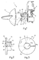
- a device for controlling the gas-burner rings of a cooking surface comprising a gas tap 2 equipped with a control knob 3 and an element 4 of a catenary 5 (which is as a whole known and of which, consequently, only the element 4 is illustrated for reasons of simplicity) for control of ignition of said gas-burner rings of the aforesaid cooking surface (known and not illustrated).
- the catenary 5 is a catenary of a standard type, preferably of the type actuated without springs, and the catenary element 4 comprises a microswitch 6, which is also of a known type and is actuated selectively by a contrast element 10 carried by an axially mobile element 11 of the gas tap 2.
- the element 11, which is also known as a whole, is provided fixed thereto with the knob 3, on an end opposite to the one coupled to the catenary 5.
- the contrast element 10 consists of a bushing, illustrated in greater detail in Figures 2 and 3, which is coupled directly, via snap action, on the mobile element 11 of the gas tap 2.
- the bushing 10 is made of an elastic material, preferably of a synthetic plastic material with which the bushing 10 itself is injection-moulded.
- the bushing 10 comprises: a mounting sleeve 12 for installation on said mobile element 11 of the gas tap 2; and a flange 14 designed to bear in use upon the microswitch 6 to actuate it as a result of a motion of translation of the mobile element 11 of the gas tap 2, said motion of translation (which takes place in the direction of the arrow illustrated in Figure 1) being exerted on the element 11 by the user, via the knob 3, whenever the element 11 itself is rotated to enable supply of combustible gas via the tap 2 to the desired gas-burner ring.
- the bushing 10 is provided with an annular detent 16, set radially on the inside, and has a radial slit 18, which interrupts its continuity without reducing appreciably the angular extent of the flange 14. In an angular position corresponding to that of the slit 18, the bushing 10 is moreover provided with a pair of circumferential slots 19a, 19b, radially internal and opposed, which interrupt the continuity of the detent 16, as is clearly illustrated in Figure 3.
- the angular extent of the slots 19a, 19b, which are preferably shaped like key seats ( Figure 3) is much greater (of at least one order of magnitude) than that of the slit 18.
- the slit 18 is divided into two portions 18a and 18b so that the angular extent of the radial slit 18 through the flange 14 (portion 18a) is of the order of a few tenths of a millimetre (approximately five tenths of a millimetre), whilst the angular extent of the slit 18 through the mounting sleeve 12 (portion 18b) is sensibly greater.
- the angular extent of the slit 18 continues to widen out progressively as it recedes from the flange 14 so that the portion 18b has a flared configuration, which simplifies production of the bushing 10 by moulding.
- the detent 16 is carried by the mounting sleeve 12 in an axial position corresponding to that of the flange 14, and the slots 19a, 19b are made flush with a first front surface 20 of the flange 14, facing, on the opposite side, a first end 21 of the sleeve 12, and extend starting from the front surface 20 and inside the sleeve 12, throughout the axial extent of the detent 16.
- the detent 16 is coupled, in use, with an annular seat 30 (Figure 1), of the known type used for housing snap rings.
- the seat 30 is made on an external side surface of the mobile element 11 of the gas tap 2.
- the flange 14 is preferably made with the first front surface 20 set flush with a second end 22 of the mounting sleeve 12, opposite to the end 21.
- the detent is shaped and positioned so that the bushing 10 may be installed on the mobile element 11 of the gas tap 2 in a reversible position, i.e., with the sleeve 12 projecting axially from the flange 14, which in use faces the microswitch 6 or else faces the opposite side with respect to the microswitch 6 itself.
- the distance of the flange 14 from the microswitch 6 can be varied without modifying the position of the seat 30, thus enabling adjustment of the travel of the microswitch 6, maintaining the same catenary 5.
- the opposed slots 19a, 19b preferably have a different angular extent.
- one first slot 19a which is set adjacent to the slit 18 (in the case in point to the portion 18a) and communicates therewith, has an angular extent smaller than that of the second slot 19b, which is set in a position diametrally opposite to the slot 19a.
- the stiffness/elasticity of the bushing 10 can be optimized, as desired, according to the dimensions of the seat 30 available on the gas tap 2.
- the annular seat 30 is moreover chosen so as to have an axial extent greater than that of an ordinary seat for a snap ring, and likewise the annular detent 16 has an axial extent (thickness) greater than the usual thickness of a snap ring.
Abstract

Description
- Figure 1 is a perspective view from above of a control device provided according to the invention; and
- Figures 2 and 3 are two orthogonal views at an enlarged scale of an essential detail of the device of Figure 1.
Claims (11)
- A device for controlling the gas-burner rings of a cooking surface comprising a gas tap equipped with a control knob and a catenary element for control of ignition of the gas-burner rings, the catenary element comprising a microswitch, which is actuated selectively by a contrast element carried axially by a mobile element of the gas tap provided with said knob; said control device being characterized in that said contrast element consists of a bushing fitted directly, via snap action, on said mobile element of the gas tap, the bushing being made of an elastic material and comprising a mounting sleeve for installation on said mobile element of the gas tap and a flange, which is designed to bear upon said microswitch to actuate it as a result of a motion of translation of the mobile element of the gas tap; the bushing being provided with a radially internal annular detent and having a radial slit that interrupts its continuity without reducing appreciably the angular extent of the flange; in an angular position corresponding to that of said slit the bushing being moreover provided with a pair of radially opposed internal circumferential slots, which interrupt the continuity of the detent.
- The control device according to Claim 1, characterized in that the angular extent of said slots is much greater than that of said slit.
- The control device according to Claim 1 or Claim 2, characterized in that said slots are shaped like key seats.
- The control device according to any one of the preceding claims, characterized in that said detent is carried by said mounting sleeve, in an axial position corresponding to that of said flange; said slots being made flush with a first front surface of said flange, facing, on the opposite side, a first end of said mounting sleeve, and extending, starting from said first front surface of the flange and within said mounting sleeve, throughout the axial extent of said detent.
- The control device according to Claim 4, characterized in that said detent is coupled in use with an annular seat made on an external side surface of said mobile element of the gas tap.
- The control device according to Claim 4 or Claim 5, characterized in that said flange is made with said first front surface set flush with a second end of said mounting sleeve opposite to the first end.
- The control device according to any one of the preceding claims, characterized in that said bushing is made of a synthetic plastic material and is obtained by injection moulding.
- The control device according to any one of the preceding claims, characterized in that the angular extent of said radial slit through said flange is in the region of a few tenths of a millimetre; said slit having, instead, the greater angular extent through said mounting sleeve; said angular extent of the slit widening progressively, in an area corresponding to said sleeve, as it recedes from the flange.
- The control device according to any one of the preceding claims, characterized in that said detent is shaped and positioned so that said bushing may be installed on said mobile element of the gas tap in a reversible position.
- The control device according to any one of the preceding claims, characterized in that said opposed slots have a different angular extent; namely, a first slot set adjacent to said slit and communicating therewith having an angular extent smaller than that of a second slot opposite to the first.
- A moulded bushing made of synthetic plastic material for installation on a device for controlling the gas-burner rings of a cooking surface, according to any one of the preceding claims.
Applications Claiming Priority (2)
| Application Number | Priority Date | Filing Date | Title |
|---|---|---|---|
| ITTO20030581 | 2003-07-25 | ||
| IT000581A ITTO20030581A1 (en) | 2003-07-25 | 2003-07-25 | INTEGRATED UNIVERSAL CONTROL UNIT FOR FIREWORKS |
Publications (3)
| Publication Number | Publication Date |
|---|---|
| EP1500881A2 true EP1500881A2 (en) | 2005-01-26 |
| EP1500881A3 EP1500881A3 (en) | 2005-06-15 |
| EP1500881B1 EP1500881B1 (en) | 2010-03-03 |
Family
ID=33485536
Family Applications (1)
| Application Number | Title | Priority Date | Filing Date |
|---|---|---|---|
| EP04103553A Active EP1500881B1 (en) | 2003-07-25 | 2004-07-23 | Integrated device for gas-cooking hobs including a gas tap and an ignitor |
Country Status (8)
| Country | Link |
|---|---|
| US (1) | US7243647B2 (en) |
| EP (1) | EP1500881B1 (en) |
| AT (1) | ATE459849T1 (en) |
| BR (1) | BRPI0403024B1 (en) |
| DE (1) | DE602004025770D1 (en) |
| ES (1) | ES2341713T3 (en) |
| IT (1) | ITTO20030581A1 (en) |
| MX (1) | MXPA04007182A (en) |
Cited By (16)
| Publication number | Priority date | Publication date | Assignee | Title |
|---|---|---|---|---|
| US7007688B2 (en) * | 2003-12-15 | 2006-03-07 | Rekrow Industrial Inc. | Heat control device of portable gas stoves |
| WO2007013014A2 (en) * | 2005-07-25 | 2007-02-01 | Arcelik Anonim Sirketi | A cooking device |
| EP1777456A2 (en) | 2005-10-21 | 2007-04-25 | Turas Gas Armatures R&D | "Y" type tap for gas furnaces or stoves with security system for shutting off the gas supply |
| WO2008135839A2 (en) * | 2007-05-04 | 2008-11-13 | Itw Industrial Components S.R.L. Con Unico Socio | Control device including a gas tap and a catenary element for burners of a cooking range |
| WO2009034445A2 (en) * | 2007-09-11 | 2009-03-19 | Itw Industrial Components S.R.L. Con Unico Socio | Rotary control device including a gas tap and a catenary element for burners of a cooking range |
| ITTO20091012A1 (en) * | 2009-12-21 | 2011-06-22 | Illinois Tool Works | IGNITION CONTROL CHAIN FOR GAS TAPS WITH OPTICAL INDICATION OF ADVANTAGE GAS TAP OPENING, FOR COOKING APPLIANCES |
| EP2383520A2 (en) | 2010-04-28 | 2011-11-02 | BSH Bosch und Siemens Hausgeräte GmbH | Gas valve with ignition device |
| EP2383519A2 (en) | 2010-04-28 | 2011-11-02 | BSH Bosch und Siemens Hausgeräte GmbH | Gas valve with ignition device |
| EP2390574A2 (en) | 2010-05-24 | 2011-11-30 | BSH Bosch und Siemens Hausgeräte GmbH | Gas valve with ignition device |
| EP2390575A2 (en) | 2010-05-24 | 2011-11-30 | BSH Bosch und Siemens Hausgeräte GmbH | Gas valve with an actuating device for an electric switch |
| WO2011082882A3 (en) * | 2009-12-17 | 2013-02-21 | BSH Bosch und Siemens Hausgeräte GmbH | Gas valve having an actuating element for an electrical switch |
| US9410525B2 (en) | 2013-08-07 | 2016-08-09 | Denso International America, Inc. | Valve controlled combustion system |
| ES2617049A1 (en) * | 2015-12-15 | 2017-06-15 | Bsh Electrodomésticos España, S.A. | Control element arrangement, and cooking point (Machine-translation by Google Translate, not legally binding) |
| WO2017209709A1 (en) * | 2016-05-30 | 2017-12-07 | Ferel Elektroni̇k Sanayi̇ Ti̇caret Anoni̇m Şi̇rketi̇ | A connection ring for gas taps |
| WO2019129405A1 (en) * | 2017-12-25 | 2019-07-04 | Arcelik Anonim Sirketi | A cooker comprising an ignition washer |
| EP3546829A1 (en) | 2018-03-28 | 2019-10-02 | Ferel Elektronik Sanay Ticaret Anonim Sirketi | A retaining ring washer for burner switching mechanism of heaters and cookers operating with gas |
Families Citing this family (8)
| Publication number | Priority date | Publication date | Assignee | Title |
|---|---|---|---|---|
| US7654820B2 (en) | 2006-12-22 | 2010-02-02 | David Deng | Control valves for heaters and fireplace devices |
| CN101382302B (en) * | 2007-09-05 | 2011-04-06 | 海尔集团公司 | Gas range electropneumatic valve preventing dry fry |
| US20100043774A1 (en) * | 2008-08-22 | 2010-02-25 | Kao Hsung Tsung | Knob igniter of a gas stove |
| CN104696433B (en) | 2010-04-12 | 2018-06-29 | 舍弗勒技术股份两合公司 | Torque converter and the piston plate component for torque converter |
| KR101623795B1 (en) * | 2014-10-07 | 2016-06-07 | 엘지전자 주식회사 | cooking appliance |
| US11085638B2 (en) | 2017-11-08 | 2021-08-10 | Illinois Tool Works Inc. | Device for controlling the ignition of gas burners of a domestic cooking appliance |
| IT201800021247A1 (en) | 2018-12-27 | 2020-06-27 | Illinois Tool Works | CONTROL DEVICE FOR IGNITION OF GAS BURNERS IN A DOMESTIC COOKING APPLIANCE |
| CN111486482A (en) * | 2020-04-23 | 2020-08-04 | 卢建强 | Gas stove handle |
Citations (11)
| Publication number | Priority date | Publication date | Assignee | Title |
|---|---|---|---|---|
| US1988595A (en) * | 1932-02-06 | 1935-01-22 | Nat Lock Washer Co | Grip ring |
| FR1597230A (en) * | 1968-02-26 | 1970-06-22 | ||
| NL6903450A (en) * | 1969-03-06 | 1970-09-08 | ||
| FR2058738A5 (en) * | 1969-09-23 | 1971-05-28 | Cepem | |
| GB1250979A (en) * | 1968-06-28 | 1971-10-27 | ||
| US3937207A (en) * | 1974-09-30 | 1976-02-10 | Winnebago Industries, Inc. | Range top hold-down and pilot light flash tube |
| US4291206A (en) * | 1978-05-09 | 1981-09-22 | Lucas Industries Limited | Contact breaker assembly |
| US4324517A (en) * | 1980-06-16 | 1982-04-13 | Sps Technologies, Inc. | Panel fastener assembly with retainer ring |
| EP0455896A2 (en) * | 1990-05-11 | 1991-11-13 | TECNOGAS S.p.A. | Automatic unit for igniting appliances containing gas rings |
| FR2782152A1 (en) * | 1998-08-05 | 2000-02-11 | Fagor S Coop | Tap and control for cooker gas supply includes safety mechanism to prevent accidental operation, and comprises integral ignition system |
| EP1035378A2 (en) * | 1999-03-08 | 2000-09-13 | Merloni Elettrodomestici S.p.A. | Household gas cooking equipment with a simplified spark ignition device |
Family Cites Families (6)
| Publication number | Priority date | Publication date | Assignee | Title |
|---|---|---|---|---|
| US3590652A (en) * | 1967-01-27 | 1971-07-06 | Robert E Strang | Sleeve and bushing structure for a torque arm speed reducer |
| US3953142A (en) * | 1972-06-21 | 1976-04-27 | Fmc Corporation | Wedge mounted machine element |
| JPS6014638A (en) * | 1983-07-01 | 1985-01-25 | Bunichi Ishimi | Speed change gear |
| SE450851B (en) * | 1986-01-24 | 1987-08-03 | Skf Mekanprodukter Ab | DEVICE FOR MOUNTING A STOCK INCLUDING SEALS |
| US5642751A (en) * | 1995-09-14 | 1997-07-01 | Crawley; Michael F. | Valve assembly |
| SE520300C2 (en) * | 2001-11-16 | 2003-06-24 | Skf Ab | Method for mounting a sleeve on a shaft and a sleeve for such mounting |
-
2003
- 2003-07-25 IT IT000581A patent/ITTO20030581A1/en unknown
-
2004
- 2004-07-23 US US10/897,432 patent/US7243647B2/en not_active Expired - Fee Related
- 2004-07-23 AT AT04103553T patent/ATE459849T1/en not_active IP Right Cessation
- 2004-07-23 EP EP04103553A patent/EP1500881B1/en active Active
- 2004-07-23 DE DE602004025770T patent/DE602004025770D1/en not_active Expired - Fee Related
- 2004-07-23 MX MXPA04007182A patent/MXPA04007182A/en active IP Right Grant
- 2004-07-23 ES ES04103553T patent/ES2341713T3/en active Active
- 2004-07-26 BR BRPI0403024-9A patent/BRPI0403024B1/en active IP Right Grant
Patent Citations (11)
| Publication number | Priority date | Publication date | Assignee | Title |
|---|---|---|---|---|
| US1988595A (en) * | 1932-02-06 | 1935-01-22 | Nat Lock Washer Co | Grip ring |
| FR1597230A (en) * | 1968-02-26 | 1970-06-22 | ||
| GB1250979A (en) * | 1968-06-28 | 1971-10-27 | ||
| NL6903450A (en) * | 1969-03-06 | 1970-09-08 | ||
| FR2058738A5 (en) * | 1969-09-23 | 1971-05-28 | Cepem | |
| US3937207A (en) * | 1974-09-30 | 1976-02-10 | Winnebago Industries, Inc. | Range top hold-down and pilot light flash tube |
| US4291206A (en) * | 1978-05-09 | 1981-09-22 | Lucas Industries Limited | Contact breaker assembly |
| US4324517A (en) * | 1980-06-16 | 1982-04-13 | Sps Technologies, Inc. | Panel fastener assembly with retainer ring |
| EP0455896A2 (en) * | 1990-05-11 | 1991-11-13 | TECNOGAS S.p.A. | Automatic unit for igniting appliances containing gas rings |
| FR2782152A1 (en) * | 1998-08-05 | 2000-02-11 | Fagor S Coop | Tap and control for cooker gas supply includes safety mechanism to prevent accidental operation, and comprises integral ignition system |
| EP1035378A2 (en) * | 1999-03-08 | 2000-09-13 | Merloni Elettrodomestici S.p.A. | Household gas cooking equipment with a simplified spark ignition device |
Cited By (21)
| Publication number | Priority date | Publication date | Assignee | Title |
|---|---|---|---|---|
| US7007688B2 (en) * | 2003-12-15 | 2006-03-07 | Rekrow Industrial Inc. | Heat control device of portable gas stoves |
| WO2007013014A2 (en) * | 2005-07-25 | 2007-02-01 | Arcelik Anonim Sirketi | A cooking device |
| WO2007013014A3 (en) * | 2005-07-25 | 2007-05-31 | Arcelik As | A cooking device |
| EP1777456A2 (en) | 2005-10-21 | 2007-04-25 | Turas Gas Armatures R&D | "Y" type tap for gas furnaces or stoves with security system for shutting off the gas supply |
| WO2008135839A2 (en) * | 2007-05-04 | 2008-11-13 | Itw Industrial Components S.R.L. Con Unico Socio | Control device including a gas tap and a catenary element for burners of a cooking range |
| WO2008135839A3 (en) * | 2007-05-04 | 2009-11-19 | Itw Industrial Components S.R.L. Con Unico Socio | Control device including a gas tap and a catenary element for burners of a cooking range |
| WO2009034445A2 (en) * | 2007-09-11 | 2009-03-19 | Itw Industrial Components S.R.L. Con Unico Socio | Rotary control device including a gas tap and a catenary element for burners of a cooking range |
| WO2009034445A3 (en) * | 2007-09-11 | 2009-05-22 | Itw Ind Components Srl | Rotary control device including a gas tap and a catenary element for burners of a cooking range |
| WO2011082882A3 (en) * | 2009-12-17 | 2013-02-21 | BSH Bosch und Siemens Hausgeräte GmbH | Gas valve having an actuating element for an electrical switch |
| ITTO20091012A1 (en) * | 2009-12-21 | 2011-06-22 | Illinois Tool Works | IGNITION CONTROL CHAIN FOR GAS TAPS WITH OPTICAL INDICATION OF ADVANTAGE GAS TAP OPENING, FOR COOKING APPLIANCES |
| WO2011084729A1 (en) * | 2009-12-21 | 2011-07-14 | Illinois Tool Works Inc. | Lighting control switch harness for gas taps of for cooking appliances with optical indication of opening of the gas tap |
| US10788217B2 (en) | 2009-12-21 | 2020-09-29 | Illinois Tool Works Inc. | Lighting control switch harness for gas taps with optical indication of opening of the gas tap, for cooking appliances |
| EP2383520A2 (en) | 2010-04-28 | 2011-11-02 | BSH Bosch und Siemens Hausgeräte GmbH | Gas valve with ignition device |
| EP2383519A2 (en) | 2010-04-28 | 2011-11-02 | BSH Bosch und Siemens Hausgeräte GmbH | Gas valve with ignition device |
| EP2390575A2 (en) | 2010-05-24 | 2011-11-30 | BSH Bosch und Siemens Hausgeräte GmbH | Gas valve with an actuating device for an electric switch |
| EP2390574A2 (en) | 2010-05-24 | 2011-11-30 | BSH Bosch und Siemens Hausgeräte GmbH | Gas valve with ignition device |
| US9410525B2 (en) | 2013-08-07 | 2016-08-09 | Denso International America, Inc. | Valve controlled combustion system |
| ES2617049A1 (en) * | 2015-12-15 | 2017-06-15 | Bsh Electrodomésticos España, S.A. | Control element arrangement, and cooking point (Machine-translation by Google Translate, not legally binding) |
| WO2017209709A1 (en) * | 2016-05-30 | 2017-12-07 | Ferel Elektroni̇k Sanayi̇ Ti̇caret Anoni̇m Şi̇rketi̇ | A connection ring for gas taps |
| WO2019129405A1 (en) * | 2017-12-25 | 2019-07-04 | Arcelik Anonim Sirketi | A cooker comprising an ignition washer |
| EP3546829A1 (en) | 2018-03-28 | 2019-10-02 | Ferel Elektronik Sanay Ticaret Anonim Sirketi | A retaining ring washer for burner switching mechanism of heaters and cookers operating with gas |
Also Published As
| Publication number | Publication date |
|---|---|
| ATE459849T1 (en) | 2010-03-15 |
| BRPI0403024B1 (en) | 2018-06-12 |
| DE602004025770D1 (en) | 2010-04-15 |
| ITTO20030581A1 (en) | 2005-01-26 |
| US20050045172A1 (en) | 2005-03-03 |
| EP1500881A3 (en) | 2005-06-15 |
| BRPI0403024A (en) | 2005-05-31 |
| EP1500881B1 (en) | 2010-03-03 |
| US7243647B2 (en) | 2007-07-17 |
| MXPA04007182A (en) | 2005-06-08 |
| ES2341713T3 (en) | 2010-06-25 |
Similar Documents
| Publication | Publication Date | Title |
|---|---|---|
| EP1500881B1 (en) | Integrated device for gas-cooking hobs including a gas tap and an ignitor | |
| EP2979035B1 (en) | Waterproof structure of operating device of gas stove and gas stove | |
| US8662102B2 (en) | Apparatus for reducing knob wobble | |
| US8534160B2 (en) | Retractable control device for domestic appliance | |
| EP2165119B1 (en) | Control device including a gas tap and a catenary element for burners of a cooking range | |
| WO2018133788A1 (en) | Waterproof passive wireless controller and control system and application thereof | |
| US8173924B2 (en) | Dual function switch assembly | |
| KR101957654B1 (en) | Panel-type control buttons | |
| WO2009034445A2 (en) | Rotary control device including a gas tap and a catenary element for burners of a cooking range | |
| US4449036A (en) | Electric cigar lighter with a snap disk forming a bimetallic switch | |
| US20190314960A1 (en) | Screwing Tool, Reversible In Rotation Direction, Encased In An Electrically Insulating Manner | |
| WO2023013242A1 (en) | Switch | |
| CN213420078U (en) | Faucet handle structure | |
| CN110246719B (en) | Knob switch and electronic equipment | |
| EP3165990B1 (en) | Command device for electrical appliances, in particular for ovens or stovetops | |
| CN112635229A (en) | Press revolution mechanic and intelligent wrist-watch | |
| CN219738062U (en) | Knob assembly | |
| US5682979A (en) | Switching assembly for gas burner valve | |
| CN217842899U (en) | Plug valve and stove using same | |
| CN219979388U (en) | Foot kicking switch and closestool | |
| JPH10326536A (en) | Rotary type electric controller knob and its fitting structure | |
| KR200385558Y1 (en) | Multi vacuum switch | |
| KR0128061Y1 (en) | Rotary knob locking apparatus | |
| KR20230132756A (en) | Electric range | |
| KR200155405Y1 (en) | A plug of washing machine |
Legal Events
| Date | Code | Title | Description |
|---|---|---|---|
| PUAI | Public reference made under article 153(3) epc to a published international application that has entered the european phase |
Free format text: ORIGINAL CODE: 0009012 |
|
| AK | Designated contracting states |
Kind code of ref document: A2 Designated state(s): AT BE BG CH CY CZ DE DK EE ES FI FR GB GR HU IE IT LI LU MC NL PL PT RO SE SI SK TR |
|
| AX | Request for extension of the european patent |
Extension state: AL HR LT LV MK |
|
| PUAL | Search report despatched |
Free format text: ORIGINAL CODE: 0009013 |
|
| AK | Designated contracting states |
Kind code of ref document: A3 Designated state(s): AT BE BG CH CY CZ DE DK EE ES FI FR GB GR HU IE IT LI LU MC NL PL PT RO SE SI SK TR |
|
| AX | Request for extension of the european patent |
Extension state: AL HR LT LV MK |
|
| 17P | Request for examination filed |
Effective date: 20051213 |
|
| AKX | Designation fees paid |
Designated state(s): AT BE BG CH CY CZ DE DK EE ES FI FR GB GR HU IE IT LI LU MC NL PL PT RO SE SI SK TR |
|
| 17Q | First examination report despatched |
Effective date: 20070216 |
|
| GRAP | Despatch of communication of intention to grant a patent |
Free format text: ORIGINAL CODE: EPIDOSNIGR1 |
|
| GRAS | Grant fee paid |
Free format text: ORIGINAL CODE: EPIDOSNIGR3 |
|
| GRAA | (expected) grant |
Free format text: ORIGINAL CODE: 0009210 |
|
| AK | Designated contracting states |
Kind code of ref document: B1 Designated state(s): AT BE BG CH CY CZ DE DK EE ES FI FR GB GR HU IE IT LI LU MC NL PL PT RO SE SI SK TR |
|
| REG | Reference to a national code |
Ref country code: GB Ref legal event code: FG4D |
|
| REG | Reference to a national code |
Ref country code: CH Ref legal event code: EP |
|
| REG | Reference to a national code |
Ref country code: IE Ref legal event code: FG4D |
|
| REF | Corresponds to: |
Ref document number: 602004025770 Country of ref document: DE Date of ref document: 20100415 Kind code of ref document: P |
|
| REG | Reference to a national code |
Ref country code: ES Ref legal event code: FG2A Ref document number: 2341713 Country of ref document: ES Kind code of ref document: T3 |
|
| REG | Reference to a national code |
Ref country code: NL Ref legal event code: VDEP Effective date: 20100303 |
|
| PG25 | Lapsed in a contracting state [announced via postgrant information from national office to epo] |
Ref country code: FI Free format text: LAPSE BECAUSE OF FAILURE TO SUBMIT A TRANSLATION OF THE DESCRIPTION OR TO PAY THE FEE WITHIN THE PRESCRIBED TIME-LIMIT Effective date: 20100303 Ref country code: AT Free format text: LAPSE BECAUSE OF FAILURE TO SUBMIT A TRANSLATION OF THE DESCRIPTION OR TO PAY THE FEE WITHIN THE PRESCRIBED TIME-LIMIT Effective date: 20100303 Ref country code: SI Free format text: LAPSE BECAUSE OF FAILURE TO SUBMIT A TRANSLATION OF THE DESCRIPTION OR TO PAY THE FEE WITHIN THE PRESCRIBED TIME-LIMIT Effective date: 20100303 Ref country code: PL Free format text: LAPSE BECAUSE OF FAILURE TO SUBMIT A TRANSLATION OF THE DESCRIPTION OR TO PAY THE FEE WITHIN THE PRESCRIBED TIME-LIMIT Effective date: 20100303 |
|
| PG25 | Lapsed in a contracting state [announced via postgrant information from national office to epo] |
Ref country code: RO Free format text: LAPSE BECAUSE OF FAILURE TO SUBMIT A TRANSLATION OF THE DESCRIPTION OR TO PAY THE FEE WITHIN THE PRESCRIBED TIME-LIMIT Effective date: 20100303 Ref country code: SE Free format text: LAPSE BECAUSE OF FAILURE TO SUBMIT A TRANSLATION OF THE DESCRIPTION OR TO PAY THE FEE WITHIN THE PRESCRIBED TIME-LIMIT Effective date: 20100303 Ref country code: NL Free format text: LAPSE BECAUSE OF FAILURE TO SUBMIT A TRANSLATION OF THE DESCRIPTION OR TO PAY THE FEE WITHIN THE PRESCRIBED TIME-LIMIT Effective date: 20100303 Ref country code: GR Free format text: LAPSE BECAUSE OF FAILURE TO SUBMIT A TRANSLATION OF THE DESCRIPTION OR TO PAY THE FEE WITHIN THE PRESCRIBED TIME-LIMIT Effective date: 20100604 Ref country code: EE Free format text: LAPSE BECAUSE OF FAILURE TO SUBMIT A TRANSLATION OF THE DESCRIPTION OR TO PAY THE FEE WITHIN THE PRESCRIBED TIME-LIMIT Effective date: 20100303 Ref country code: CY Free format text: LAPSE BECAUSE OF FAILURE TO SUBMIT A TRANSLATION OF THE DESCRIPTION OR TO PAY THE FEE WITHIN THE PRESCRIBED TIME-LIMIT Effective date: 20100303 Ref country code: BE Free format text: LAPSE BECAUSE OF FAILURE TO SUBMIT A TRANSLATION OF THE DESCRIPTION OR TO PAY THE FEE WITHIN THE PRESCRIBED TIME-LIMIT Effective date: 20100303 |
|
| PG25 | Lapsed in a contracting state [announced via postgrant information from national office to epo] |
Ref country code: CZ Free format text: LAPSE BECAUSE OF FAILURE TO SUBMIT A TRANSLATION OF THE DESCRIPTION OR TO PAY THE FEE WITHIN THE PRESCRIBED TIME-LIMIT Effective date: 20100303 Ref country code: BG Free format text: LAPSE BECAUSE OF FAILURE TO SUBMIT A TRANSLATION OF THE DESCRIPTION OR TO PAY THE FEE WITHIN THE PRESCRIBED TIME-LIMIT Effective date: 20100603 Ref country code: SK Free format text: LAPSE BECAUSE OF FAILURE TO SUBMIT A TRANSLATION OF THE DESCRIPTION OR TO PAY THE FEE WITHIN THE PRESCRIBED TIME-LIMIT Effective date: 20100303 |
|
| PLBE | No opposition filed within time limit |
Free format text: ORIGINAL CODE: 0009261 |
|
| STAA | Information on the status of an ep patent application or granted ep patent |
Free format text: STATUS: NO OPPOSITION FILED WITHIN TIME LIMIT |
|
| PG25 | Lapsed in a contracting state [announced via postgrant information from national office to epo] |
Ref country code: PT Free format text: LAPSE BECAUSE OF FAILURE TO SUBMIT A TRANSLATION OF THE DESCRIPTION OR TO PAY THE FEE WITHIN THE PRESCRIBED TIME-LIMIT Effective date: 20100705 Ref country code: DK Free format text: LAPSE BECAUSE OF FAILURE TO SUBMIT A TRANSLATION OF THE DESCRIPTION OR TO PAY THE FEE WITHIN THE PRESCRIBED TIME-LIMIT Effective date: 20100303 |
|
| 26N | No opposition filed |
Effective date: 20101206 |
|
| PG25 | Lapsed in a contracting state [announced via postgrant information from national office to epo] |
Ref country code: MC Free format text: LAPSE BECAUSE OF NON-PAYMENT OF DUE FEES Effective date: 20100731 |
|
| REG | Reference to a national code |
Ref country code: CH Ref legal event code: PL |
|
| GBPC | Gb: european patent ceased through non-payment of renewal fee |
Effective date: 20100723 |
|
| PG25 | Lapsed in a contracting state [announced via postgrant information from national office to epo] |
Ref country code: LI Free format text: LAPSE BECAUSE OF NON-PAYMENT OF DUE FEES Effective date: 20100731 Ref country code: CH Free format text: LAPSE BECAUSE OF NON-PAYMENT OF DUE FEES Effective date: 20100731 Ref country code: DE Free format text: LAPSE BECAUSE OF NON-PAYMENT OF DUE FEES Effective date: 20110201 |
|
| REG | Reference to a national code |
Ref country code: DE Ref legal event code: R119 Ref document number: 602004025770 Country of ref document: DE Effective date: 20110201 |
|
| PG25 | Lapsed in a contracting state [announced via postgrant information from national office to epo] |
Ref country code: IE Free format text: LAPSE BECAUSE OF NON-PAYMENT OF DUE FEES Effective date: 20100723 Ref country code: GB Free format text: LAPSE BECAUSE OF NON-PAYMENT OF DUE FEES Effective date: 20100723 |
|
| PG25 | Lapsed in a contracting state [announced via postgrant information from national office to epo] |
Ref country code: LU Free format text: LAPSE BECAUSE OF NON-PAYMENT OF DUE FEES Effective date: 20100723 Ref country code: HU Free format text: LAPSE BECAUSE OF FAILURE TO SUBMIT A TRANSLATION OF THE DESCRIPTION OR TO PAY THE FEE WITHIN THE PRESCRIBED TIME-LIMIT Effective date: 20100904 |
|
| REG | Reference to a national code |
Ref country code: FR Ref legal event code: PLFP Year of fee payment: 12 |
|
| REG | Reference to a national code |
Ref country code: FR Ref legal event code: PLFP Year of fee payment: 13 |
|
| REG | Reference to a national code |
Ref country code: FR Ref legal event code: PLFP Year of fee payment: 14 |
|
| REG | Reference to a national code |
Ref country code: FR Ref legal event code: PLFP Year of fee payment: 15 |
|
| PGFP | Annual fee paid to national office [announced via postgrant information from national office to epo] |
Ref country code: TR Payment date: 20230707 Year of fee payment: 20 Ref country code: IT Payment date: 20230720 Year of fee payment: 20 Ref country code: ES Payment date: 20230804 Year of fee payment: 20 |
|
| PGFP | Annual fee paid to national office [announced via postgrant information from national office to epo] |
Ref country code: FR Payment date: 20230725 Year of fee payment: 20 |
|
| P01 | Opt-out of the competence of the unified patent court (upc) registered |
Effective date: 20231101 |