EP1500737B1 - Waschmaschine - Google Patents
Waschmaschine Download PDFInfo
- Publication number
- EP1500737B1 EP1500737B1 EP04251645A EP04251645A EP1500737B1 EP 1500737 B1 EP1500737 B1 EP 1500737B1 EP 04251645 A EP04251645 A EP 04251645A EP 04251645 A EP04251645 A EP 04251645A EP 1500737 B1 EP1500737 B1 EP 1500737B1
- Authority
- EP
- European Patent Office
- Prior art keywords
- washing machine
- machine according
- drum
- guide
- pulsator
- Prior art date
- Legal status (The legal status is an assumption and is not a legal conclusion. Google has not performed a legal analysis and makes no representation as to the accuracy of the status listed.)
- Expired - Lifetime
Links
Images


Classifications
-
- D—TEXTILES; PAPER
- D06—TREATMENT OF TEXTILES OR THE LIKE; LAUNDERING; FLEXIBLE MATERIALS NOT OTHERWISE PROVIDED FOR
- D06F—LAUNDERING, DRYING, IRONING, PRESSING OR FOLDING TEXTILE ARTICLES
- D06F23/00—Washing machines with receptacles, e.g. perforated, having a rotary movement, e.g. oscillatory movement, the receptacle serving both for washing and for centrifugally separating water from the laundry
- D06F23/06—Washing machines with receptacles, e.g. perforated, having a rotary movement, e.g. oscillatory movement, the receptacle serving both for washing and for centrifugally separating water from the laundry and rotating or oscillating about an inclined axis
-
- D—TEXTILES; PAPER
- D06—TREATMENT OF TEXTILES OR THE LIKE; LAUNDERING; FLEXIBLE MATERIALS NOT OTHERWISE PROVIDED FOR
- D06F—LAUNDERING, DRYING, IRONING, PRESSING OR FOLDING TEXTILE ARTICLES
- D06F17/00—Washing machines having receptacles, stationary for washing purposes, wherein the washing action is effected solely by circulation or agitation of the washing liquid
- D06F17/06—Washing machines having receptacles, stationary for washing purposes, wherein the washing action is effected solely by circulation or agitation of the washing liquid by rotary impellers
Definitions
- the present invention relates to a washing machine including a tub containing a rotatably mounted drum to receive laundry to be washed and a pulsator for agitating laundry.
- a conventional drum-type washing machine includes a housing having a door hinged to the front thereof, a cylindrical tub disposed in the housing having a rotary drum rotatably mounted therein and a motor for rotating the drum in each direction.
- a laundry agitating or lifting element is mounted on the inner wall of the drum to agitate laundry during a wash cycle.
- the drum rotates and the lifting elements agitate laundry by lifting it upwardly so that it drops due to gravity.
- the laundry is repeatedly lifted and dropped during a wash cycle to agitate it.
- the efficiency of a wash cycle is, at least in part, determined by friction generated between articles of laundry or friction between the laundry and the drum, in addition to agitation of the laundry.
- the duration of the wash cycle is relatively long and consumption of detergent is high.
- a drum-type washing machine disclosed in Korean patent No. 0144329 has been proposed.
- a pulsator is installed for rotation about the same axis as the axis about which the rotary drum rotates.
- the pulsator still does not sufficiently agitate the laundry and apply sufficient physical force to it to increase the effectiveness of the wash cycle.
- washing machine comprising a tub containing a rotatably mounted drum to receive laundry to be washed and a pulsator for agitating laundry, wherein a mechanism connecting the rotary drum to the pulsator operable to cause the pulsator to rotate in response to rotation of the rotatably mounted drum, the washing machine further comprising a guide unit to guide the pulsator.
- a washing machine is characterised by the guide unit comprising a guide surface slidably contacting with a rotating plate of the pulsator and formed with a central hole to allow a rotating shaft connected to the rotary plate to pass through the guide surface and a guide step forwardly projected from an edge of the guide surface to guide a sidewall of the rotating plate.
- the guide unit comprises a mounting part extending from an edge of the guide surface such that the mounting part projects forward from the edge of the guide surface thereby providing the guide step.
- the mounting part and the guide surface are disposed in a seat formed on the drum.
- the guide unit is integrated into a single structure with a seat formed on the drum.
- the seat is formed at a predetermined position in the rotary drum to mount the pulsator in the rotary drum.
- the seat is a concavely depressed portion of a rear wall of the rotary drum.
- the washing machine comprises a bushing positioned at an inner circumferential surface of the central hole and slidably contacting the rotating shaft.
- the mechanism comprises a gear train.
- the gear train comprises a stationary ring gear mounted to the tub and a pinion in meshing engagement with the ring gear mounted to the pulsator such that the pinion rotates about its own axis as it travels along the ring gear during rotation of the drum.
- the axis of rotation of the pulsator is spaced from the axis of rotation of the drum.
- the washing machine comprises a plurality of pulsators spaced from the axis of rotation of the drum.
- a plurality of washing blades may be mounted to the rotating plate, the washing blades being projected toward an interior of the rotary drum.
- the plurality of washing blades are radially arranged on a front surface of the rotating plate.
- the guide surface is a circular shape.
- the rotating plate is formed to be forwardly convex at a central portion thereof.
- the rotary drum rotates in alternating directions.
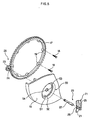
- a washing machine according to a first embodiment of the present invention is illustrated in Figure 1 and comprises a housing 1, a door 2 hinged to a front of the housing 1, a cylindrical water tub 3 supported by a support unit 60, a rotatably mounted drum 4 mounted in the tub 4 for rotation in alternating directions and a motor 5.
- the tub 3 receives water during a wash cycle and is downwardly inclined from the front wall 6 to a rear wall 7 away from the door 2.
- a water supply pipe 9 is connected to an upper portion of a sidewall 8 of the water tub 3 to supply water to the water tub 3.
- a water drain pipe 10 is connected to a lower portion of the sidewall of the water tub 3 to discharge water from the tub 3.
- a plurality of perforations are formed in the sidewall 12 of the rotary drum 4 through which the water passes between the tub 3 and the drum 4. Further, a lifter 14 is laterally mounted on the sidewall 12 of the rotary drum 4. A pulsator 20 is rotatably mounted to a rear wall 15 of the rotary drum 4 to increase washing efficiency. A drive shaft 16 extends from the rear wall 15 of the rotary drum 4 through the tub 3 and is connected to the motor 5.
- the rotary drum 4 is coaxially disposed in the tub 3 and the drive shaft 16 is coaxial with the central axis.
- a rotation guide unit 29 is mounted between the rear wall 15 of the drum 4 and the rear wall 7 of the tub 3 and rotates the pulsator 20 in response to rotation of the rotary drum 4.
- a plurality of pulsators 20 are arranged around the centre of the rear wall 15 of the rotary drum 4 at regular angular intervals.
- the pulsator 20 comprises a rotatable plate 21 having washing blades 25 radially arranged on a front surface of the plate 21 and a shaft 22.
- One end of the shaft 22 is mounted in a central channel 26 formed through a centre of the plate 21 to allow the shaft 22 to be inserted into the plate 21.
- a guide member 30 is placed between the plate 21 and the rear wall 15 of the drum 4.
- a depression or seat 40 is formed in the rear wall 15 in which the guide member 30 is located.
- the guide member 29 for rotating the pulsator 20 comprises a ring gear 17 mounted to the rear wall 7 of the water tub 3 and a pinion 23 in meshing engagement with the ring gear 17 so that it rotates in response to rotation of the ring gear 17.
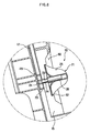
- the guide member 30 comprises a plate-shaped guide part 32, a cylindrical mounting part 33 and a cylindrical shaft guide part 34.
- the guide part 32 slidably contacts with the rear surface of the plate 21, and has a central hole 31 through which the shaft 22 passes.
- the mounting part 33 extends around an edge of the guide part 32 and is located in the seat 40.
- the shaft guide part 34 rearwardly extends from the central hole 31 and the shaft 22 passes through it.
- the mounting part 33 is mounted to the guide part 32 so as to project slightly forwardly from the guide part 32 at a front end of the mounting part 33 to form a guide step 35 to guide and surround a sidewall of the plate 21.
- the mounting part 33 has first bosses 37 on inside portions of a rear end of the mounting part 33.
- First setscrews 36 are tightened to the first bosses 37 to fasten the guide member 30 to the seat 40 formed in the rear wall 15 of the drum 4. Further, the shaft guide part 34 has a bushing 38 in a front portion of the shaft guide part 34 which slidably contacts the shaft 22.
- the shaft 22 passes through the central hole 31 of the guide member 30 and one end is received in the central channel 26 of plate 21.
- a middle portion of the shaft 22 slidably contacts the bushing 38 of the guide member 30 and the other end of the shaft 22 is received in an insertion hole 24 formed in the centre of the pinion 23.
- the pinion 23 of the rotation guide member 29 rotates along the outer circumferential surface of the ring gear 17.
- the ring gear 17 has second bosses 19 at an inner circumferential surface thereof and into which second setscrews 18 locate to lock the ring gear 17 to the tub 3.
- the rear wall 15 of the rotary drum 4 has a concave depression to form the circular seat 40, with the guide member 30 being seated in the seat 40.
- a through hole 41 is formed at a centre of the seat 40 to allow the shaft 22 of the pulsator 20 to pass through it.
- Screw holes 42 are formed on the seat 40, thus allowing the first setscrews 36 to pass through the seat 40 prior to being tightened to the first bosses 37 of the guide member 30.
- the pinion 23 rotates together with it.
- the pinion 23 rotates about its own axis whilst it revolves around the outside of the ring gear 17 which is stationary on the rear wall 15 of the tub 3.
- drive is transmitted to the plate 21 through the shaft 22, thus making the plate 21 revolve and rotate in the drum 4.
- the operational effect of the plate 21 caused by its rotation is as follows. As the drum 4 is rearwardly inclined, laundry moves rearwards during a wash cycle and contacts the plate 21 which agitates the laundry as the rotary drum rotates. As the plate 21 also rotates on its own axis, the laundry coming into contact with the plate 21 is twisted and agitated further.
- the pulsator 20 supplements the lifter 14 so as to increase the amount by which the laundry is agitated, thus enhancing the washing effect.
- the plate 21 and the shaft 22 of the second embodiment are the same as the plate and shaft of the pulsator of the first embodiment, in terms of construction.
- a guide unit 50 included in the washing machine according to the second embodiment is integrated with a rear wall 15 of a rotary drum 4.
- the guide unit 50 comprises a circular guide surface 51, a guide step 52, a central hole 53, and a bushing 54.
- the circular guide surface 51 slidably contacts the plate 21.
- the guide step 52 is forwardly projected from an edge of the guide surface 51 to guide a sidewall of the rotating plate 21.
- the central hole 53 is formed at a centre of the guide surface 51 to allow the shaft 22 to pass through the guide surface 51.
- the bushing 54 is placed at an inner circumferential surface of the central hole 53, and slidably contacts with the rotating shaft 22.
- washing machine according to the second embodiment is the same as the washing machine according to the first embodiment.
- the present invention provides a washing machine which has a rotatable pulsator at a rear wall of a rotary drum which aids operation of the lifter to agitate laundry, thereby enhancing the washing effect by reducing the washing time and detergent consumption.
Landscapes
- Engineering & Computer Science (AREA)
- Textile Engineering (AREA)
- Main Body Construction Of Washing Machines And Laundry Dryers (AREA)
Claims (16)
- Waschmaschine, enthaltend einen Bottich (3), der eine drehbar montierte Trommel (4) zum Empfangen von zu waschender Wäsche und einen Pulsator (20) zum Bewegen von Wäsche enthält, wobei ein Mechanismus, der die drehbare Trommel (4) mit dem Pulsator (20) verbindet, betriebsfähig ist, um zu bewirken, dass der Pulsator (20) sich als Reaktion auf Drehung der drehbar montierten Trommel (4) dreht, die Waschmaschine weiterhin umfassend eine Führungseinheit (30) zum Führen des Pulsators (20), gekennzeichnet durch die Führungseinheit (30) umfassend eine Führungsoberfläche (32), die verschiebbar eine drehende Platte (21) des Pulsators (20) berührt und mit einem zentralen Loch (31) gebildet ist, um einer drehenden Welle (22), die mit der drehenden Platte (21) verbunden ist, zu gestatten, durch die Führungsoberfläche (32) zu passieren, und eine Führungsstufe (35), die von einem Rand der Führungsoberfläche (32) nach vorne hervorsteht, um eine Seitenwand der drehenden Platte (21) zu führen.
- Waschmaschine nach Anspruch 1, wobei die Führungseinheit (30) ein Befestigungsteil (33) umfasst, das sich von einem Rand der Führungsoberfläche (32) derart erstreckt, dass das Befestigungsteil (33) von dem Rand der Führungsoberfläche (32) nach vorne hervorsteht und dadurch die Führungsstufe (35) bereitstellt.
- Waschmaschine nach Anspruch 2, wobei das Befestigungsteil (33) und die Führungsoberfläche (32) in einem Sitz (40), der an der Trommel (4) gebildet ist, angeordnet sind.
- Waschmaschine nach Anspruch 1, wobei die Führungseinheit (30) in eine einzelne Struktur mit einem Sitz (40), der an der Trommel (4) gebildet ist, integriert ist.
- Waschmaschine nach den Ansprüchen 3 und 4, wobei der Sitz (40) an einer im Voraus bestimmten Position in der drehenden Trommel (4) gebildet ist, um den Pulsator (20) in der drehenden Trommel (4) zu montieren.
- Waschmaschine nach Anspruch 5, wobei der Sitz (40) ein konkav vertiefter Abschnitt einer Hinterwand (15) der drehenden Trommel (4) ist.
- Waschmaschine nach einem der vorstehenden Ansprüche, umfassend eine Buchse (38), die an einer inneren Umfangsoberfläche des zentralen Lochs (31) positioniert ist und die drehende Welle (22) verschiebbar berührt.
- Waschmaschine nach einem der vorstehenden Ansprüche, wobei der Mechanismus ein Zahnradgetriebe umfasst.
- Waschmaschine nach Anspruch 8, wobei das Zahnradgetriebe einen stationären Zahnkranz (17) umfasst, der an dem Bottich (3) angebracht ist, und ein Ritzel (23) im Eingriff mit dem Zahnkranz (17), das an dem Pulsator (20) derart angebracht ist, dass das Ritzel (23) sich um seine eigene Achse dreht, wenn es während der Drehung der Trommel (4) entlang dem Zahnkranz (17) wandert.
- Waschmaschine nach einem der vorstehenden Ansprüche, wobei die Drehachse des Pulsators mit Abstand von der Drehachse der Trommel (4) angeordnet ist.
- Waschmaschine nach Anspruch 10, umfassend eine Vielzahl von Pulsatoren, die mit Abstand von der Drehachse der Trommel angeordnet sind.
- Waschmaschine nach einem der vorstehenden Ansprüche, weiter umfassend eine Vielzahl von Waschflügeln (25), die an der drehenden Platte (21) angebracht sind, wobei die Waschflügel (25) zu einem Inneneren der drehenden Trommel (4) hervorragen.
- Waschmaschine nach Anspruch 12, wobei die Vielzahl von Waschflügeln (25) auf einer vorderen Oberfläche der drehenden Platte (21) radial angeordnet ist.
- Waschmaschine nach einem der vorstehenden Ansprüche, wobei die Führungsoberfläche 32 eine kreisförmige Form hat.
- Waschmaschine nach einem der vorstehenden Ansprüche, wobei die drehende Platte (21) gebildet ist, um an einem zentralen Abschnitt davon vorwärts konvex zu sein.
- Waschmaschine nach einem der vorstehenden Ansprüche, wobei die drehende Trommel (4) sich in abwechselnde Richtungen dreht.
Applications Claiming Priority (2)
| Application Number | Priority Date | Filing Date | Title |
|---|---|---|---|
| KR2003049583 | 2003-07-19 | ||
| KR1020030049583A KR100997145B1 (ko) | 2003-07-19 | 2003-07-19 | 회전가능한 펄세이터가 구비된 드럼세탁기 |
Publications (3)
| Publication Number | Publication Date |
|---|---|
| EP1500737A2 EP1500737A2 (de) | 2005-01-26 |
| EP1500737A3 EP1500737A3 (de) | 2007-03-07 |
| EP1500737B1 true EP1500737B1 (de) | 2010-04-28 |
Family
ID=33487930
Family Applications (1)
| Application Number | Title | Priority Date | Filing Date |
|---|---|---|---|
| EP04251645A Expired - Lifetime EP1500737B1 (de) | 2003-07-19 | 2004-03-22 | Waschmaschine |
Country Status (4)
| Country | Link |
|---|---|
| US (1) | US7331202B2 (de) |
| EP (1) | EP1500737B1 (de) |
| KR (1) | KR100997145B1 (de) |
| DE (1) | DE602004026807D1 (de) |
Families Citing this family (15)
| Publication number | Priority date | Publication date | Assignee | Title |
|---|---|---|---|---|
| KR101462171B1 (ko) * | 2009-10-22 | 2014-11-21 | 삼성전자주식회사 | 세탁기용 펄세이터장치 및 이를 갖는 세탁기 |
| US20150059415A1 (en) * | 2013-08-30 | 2015-03-05 | Jared Greiman | Washing machine with agitator |
| JP2017018277A (ja) * | 2015-07-09 | 2017-01-26 | アクア株式会社 | ドラム式洗濯機 |
| JP6689521B2 (ja) | 2015-12-16 | 2020-04-28 | 青島海爾洗衣机有限公司QingDao Haier Washing Machine Co.,Ltd. | ドラム式洗濯機 |
| KR101936638B1 (ko) | 2017-06-21 | 2019-01-09 | 엘지전자 주식회사 | 세탁기 |
| CN107964757B (zh) * | 2017-12-26 | 2022-04-08 | 佛山海尔滚筒洗衣机有限公司 | 一种双动力滚筒洗衣机及其控制方法 |
| CN108866949B (zh) * | 2018-02-07 | 2020-02-21 | 无锡小天鹅电器有限公司 | 用于滚筒洗衣机的行星齿轮部装以及滚筒洗衣机 |
| WO2019153594A1 (zh) * | 2018-02-07 | 2019-08-15 | 无锡小天鹅电器有限公司 | 滚筒洗衣机 |
| JP7038802B2 (ja) | 2018-02-07 | 2022-03-18 | ▲無▼▲錫▼小天鵝電器有限公司 | ドラム式洗濯機 |
| CN108866940B (zh) * | 2018-02-07 | 2019-12-17 | 无锡小天鹅电器有限公司 | 滚筒洗衣机 |
| JP6963682B2 (ja) * | 2018-02-07 | 2021-11-10 | ▲無▼▲錫▼小天鵝電器有限公司Wuxi Little Swan Electric Co., Ltd. | ドラム式洗濯機用の遊星歯車部材及びドラム式洗濯機 |
| CN108866923B (zh) * | 2018-02-07 | 2020-04-14 | 无锡小天鹅电器有限公司 | 滚筒洗衣机 |
| CN110219128B (zh) * | 2018-03-02 | 2022-08-19 | 青岛海尔洗衣机有限公司 | 波轮和包括该波轮的衣物处理装置 |
| CN109853184A (zh) * | 2019-03-29 | 2019-06-07 | 周仲良 | 一种便于清洁的波轮 |
| CN114934369B (zh) * | 2022-06-30 | 2024-07-05 | 海信冰箱有限公司 | 一种洗衣机 |
Family Cites Families (10)
| Publication number | Priority date | Publication date | Assignee | Title |
|---|---|---|---|---|
| BE546058A (de) * | 1955-04-15 | |||
| JPH0732832B2 (ja) * | 1991-07-16 | 1995-04-12 | 株式会社金星社 | パルセータとドラムとの複合洗濯機 |
| KR0144329B1 (ko) | 1993-10-30 | 1998-10-01 | 배순훈 | 펄세이터를 갖춘 드럼식 세탁기 |
| KR0161045B1 (ko) * | 1994-02-28 | 1998-12-15 | 김광호 | 세탁기의 구동장치 |
| KR0158263B1 (ko) * | 1995-12-15 | 1998-12-15 | 배순훈 | 이중펄세이터를 갖는 세탁기 |
| KR100186729B1 (ko) | 1996-05-31 | 1999-05-15 | 배순훈 | 소형펄세이터를 갖는 세탁기 |
| KR980002346A (ko) * | 1996-06-29 | 1998-03-30 | 배순훈 | 세탁기의 펄세이터장치 |
| US5865046A (en) * | 1996-07-31 | 1999-02-02 | Daewoo Electronics Co., Ltd. | Clothes washer having a pulsator apparatus |
| KR19980085150A (ko) * | 1997-05-28 | 1998-12-05 | 배순훈 | 세탁기의 교반장치 |
| KR200266764Y1 (ko) | 1998-06-22 | 2002-06-24 | 윤종용 | 보조펄세이터를구비한세탁기 |
-
2003
- 2003-07-19 KR KR1020030049583A patent/KR100997145B1/ko not_active Expired - Fee Related
-
2004
- 2004-03-22 EP EP04251645A patent/EP1500737B1/de not_active Expired - Lifetime
- 2004-03-22 DE DE602004026807T patent/DE602004026807D1/de not_active Expired - Lifetime
- 2004-03-29 US US10/810,647 patent/US7331202B2/en not_active Expired - Fee Related
Also Published As
| Publication number | Publication date |
|---|---|
| KR20050010365A (ko) | 2005-01-27 |
| KR100997145B1 (ko) | 2010-11-30 |
| DE602004026807D1 (de) | 2010-06-10 |
| EP1500737A2 (de) | 2005-01-26 |
| EP1500737A3 (de) | 2007-03-07 |
| US7331202B2 (en) | 2008-02-19 |
| US20050011235A1 (en) | 2005-01-20 |
Similar Documents
| Publication | Publication Date | Title |
|---|---|---|
| EP1500737B1 (de) | Waschmaschine | |
| KR101275198B1 (ko) | 드럼세탁기 및 그에 적용되는 드럼 제조방법 | |
| US5950460A (en) | Washing machine with agitator | |
| US20130145894A1 (en) | Knob assembly and washing machine having the same | |
| JP2004209208A (ja) | ドラム式洗濯機 | |
| US5727404A (en) | Washing machine with a double pulsator | |
| KR20150105092A (ko) | 세탁기 및 이에 구비되는 세탁조의 제조방법 | |
| US4387580A (en) | Automatic washer energy absorbing spin delay mechanism | |
| US7171828B2 (en) | Washing machine | |
| KR20010000993A (ko) | 세탁기용 펄세이터 | |
| US5823019A (en) | Washing machine | |
| EP0957195A2 (de) | Waschmaschine | |
| US7610781B2 (en) | Drum type washing machine | |
| JP2015223318A (ja) | 洗濯機 | |
| KR20180136084A (ko) | 벽걸이형 세탁기 및 그의 리어 패널 | |
| US6986271B2 (en) | Washing machine | |
| US5894745A (en) | Agitator of a washing machine | |
| KR100459140B1 (ko) | 세탁기 | |
| US5784904A (en) | Washing machine with a compound pulsator having a plurality of sub-pulsators | |
| JPH07114873B2 (ja) | ドラム式洗濯・乾燥機 | |
| KR102596993B1 (ko) | 세탁기 | |
| CN222834614U (zh) | 门体洗涤机构及洗涤设备 | |
| US5715708A (en) | Washing machine equipped with a washing tub of a multiple-stairstep shape | |
| WO2015184958A1 (zh) | 滚筒式洗衣机 | |
| GB2321064A (en) | Spin tub for a washing machine |
Legal Events
| Date | Code | Title | Description |
|---|---|---|---|
| PUAI | Public reference made under article 153(3) epc to a published international application that has entered the european phase |
Free format text: ORIGINAL CODE: 0009012 |
|
| AK | Designated contracting states |
Kind code of ref document: A2 Designated state(s): AT BE BG CH CY CZ DE DK EE ES FI FR GB GR HU IE IT LI LU MC NL PL PT RO SE SI SK TR |
|
| AX | Request for extension of the european patent |
Extension state: AL LT LV MK |
|
| PUAL | Search report despatched |
Free format text: ORIGINAL CODE: 0009013 |
|
| AK | Designated contracting states |
Kind code of ref document: A3 Designated state(s): AT BE BG CH CY CZ DE DK EE ES FI FR GB GR HU IE IT LI LU MC NL PL PT RO SE SI SK TR |
|
| AX | Request for extension of the european patent |
Extension state: AL LT LV MK |
|
| 17P | Request for examination filed |
Effective date: 20070816 |
|
| AKX | Designation fees paid |
Designated state(s): DE FR GB |
|
| 17Q | First examination report despatched |
Effective date: 20080918 |
|
| GRAP | Despatch of communication of intention to grant a patent |
Free format text: ORIGINAL CODE: EPIDOSNIGR1 |
|
| RIN1 | Information on inventor provided before grant (corrected) |
Inventor name: KIM, HYUN SOOK Inventor name: YANG, BYOUNG YULL Inventor name: OAK, SEONG MIN Inventor name: YANG, HYE SOON Inventor name: PARK, SEON-WOO Inventor name: PYO, SANG-YEON Inventor name: KIM, HYUNG-GYOON Inventor name: PARK, JAE-RYONG401-1603 JOOGONG APT. |
|
| GRAS | Grant fee paid |
Free format text: ORIGINAL CODE: EPIDOSNIGR3 |
|
| GRAA | (expected) grant |
Free format text: ORIGINAL CODE: 0009210 |
|
| AK | Designated contracting states |
Kind code of ref document: B1 Designated state(s): DE FR GB |
|
| REG | Reference to a national code |
Ref country code: GB Ref legal event code: FG4D |
|
| REF | Corresponds to: |
Ref document number: 602004026807 Country of ref document: DE Date of ref document: 20100610 Kind code of ref document: P |
|
| PLBE | No opposition filed within time limit |
Free format text: ORIGINAL CODE: 0009261 |
|
| STAA | Information on the status of an ep patent application or granted ep patent |
Free format text: STATUS: NO OPPOSITION FILED WITHIN TIME LIMIT |
|
| 26N | No opposition filed |
Effective date: 20110131 |
|
| PGFP | Annual fee paid to national office [announced via postgrant information from national office to epo] |
Ref country code: GB Payment date: 20110315 Year of fee payment: 8 Ref country code: DE Payment date: 20110329 Year of fee payment: 8 Ref country code: FR Payment date: 20110407 Year of fee payment: 8 |
|
| GBPC | Gb: european patent ceased through non-payment of renewal fee |
Effective date: 20120322 |
|
| REG | Reference to a national code |
Ref country code: FR Ref legal event code: ST Effective date: 20121130 |
|
| PG25 | Lapsed in a contracting state [announced via postgrant information from national office to epo] |
Ref country code: GB Free format text: LAPSE BECAUSE OF NON-PAYMENT OF DUE FEES Effective date: 20120322 Ref country code: FR Free format text: LAPSE BECAUSE OF NON-PAYMENT OF DUE FEES Effective date: 20120402 |
|
| REG | Reference to a national code |
Ref country code: DE Ref legal event code: R119 Ref document number: 602004026807 Country of ref document: DE Effective date: 20121002 |
|
| PG25 | Lapsed in a contracting state [announced via postgrant information from national office to epo] |
Ref country code: DE Free format text: LAPSE BECAUSE OF NON-PAYMENT OF DUE FEES Effective date: 20121002 |