EP1500620A1 - Elevator - Google Patents

Elevator Download PDF

Info

Publication number
EP1500620A1
EP1500620A1 EP02720637A EP02720637A EP1500620A1 EP 1500620 A1 EP1500620 A1 EP 1500620A1 EP 02720637 A EP02720637 A EP 02720637A EP 02720637 A EP02720637 A EP 02720637A EP 1500620 A1 EP1500620 A1 EP 1500620A1
Authority
EP
European Patent Office
Prior art keywords
sheave
car
driving
hoistway
counterweight
Prior art date
Legal status (The legal status is an assumption and is not a legal conclusion. Google has not performed a legal analysis and makes no representation as to the accuracy of the status listed.)
Withdrawn
Application number
EP02720637A
Other languages
German (de)
French (fr)
Other versions
EP1500620A4 (en
Inventor
Shuki c/o Mitsubishi Denki K.K. HAMAGUCHI
Current Assignee (The listed assignees may be inaccurate. Google has not performed a legal analysis and makes no representation or warranty as to the accuracy of the list.)
Mitsubishi Electric Corp
Original Assignee
Mitsubishi Electric Corp
Priority date (The priority date is an assumption and is not a legal conclusion. Google has not performed a legal analysis and makes no representation as to the accuracy of the date listed.)
Filing date
Publication date
Application filed by Mitsubishi Electric Corp filed Critical Mitsubishi Electric Corp
Publication of EP1500620A1 publication Critical patent/EP1500620A1/en
Publication of EP1500620A4 publication Critical patent/EP1500620A4/en
Withdrawn legal-status Critical Current

Links

Images

Classifications

    • BPERFORMING OPERATIONS; TRANSPORTING
    • B66HOISTING; LIFTING; HAULING
    • B66BELEVATORS; ESCALATORS OR MOVING WALKWAYS
    • B66B11/00Main component parts of lifts in, or associated with, buildings or other structures
    • B66B11/04Driving gear ; Details thereof, e.g. seals
    • BPERFORMING OPERATIONS; TRANSPORTING
    • B66HOISTING; LIFTING; HAULING
    • B66BELEVATORS; ESCALATORS OR MOVING WALKWAYS
    • B66B11/00Main component parts of lifts in, or associated with, buildings or other structures
    • B66B11/0035Arrangement of driving gear, e.g. location or support
    • B66B11/0045Arrangement of driving gear, e.g. location or support in the hoistway
    • BPERFORMING OPERATIONS; TRANSPORTING
    • B66HOISTING; LIFTING; HAULING
    • B66BELEVATORS; ESCALATORS OR MOVING WALKWAYS
    • B66B11/00Main component parts of lifts in, or associated with, buildings or other structures
    • B66B11/0065Roping
    • B66B11/008Roping with hoisting rope or cable operated by frictional engagement with a winding drum or sheave

Definitions

  • the present invention relates to an elevator apparatus in which a driving machine is arranged in an upper portion of the hoistway.
  • JP 10-139321 A discloses a conventional example of a so-called machine-room-less type elevator apparatus in which no machine room is provided in an upper portion of the hoistway and in which a driving machine is provided in the upper portion of the hoistway.
  • this type of elevator apparatus is advantageous in that the height of the building can be reduced.
  • it is necessary to secure a space for arranging the driving machine in the upper portion of the hoistway.
  • the space inside the hoistway be utilized as efficiently as possible.
  • the present invention has been made with a view toward solving the above problem in the prior art. It is an object of the present invention to provide an elevator apparatus which makes it possible to efficiently utilize the space inside the hoistway and to minimize the sectional area of the hoistway.
  • an elevator apparatus comprising: a hoistway; a car raised and lowered in the hoistway; a car suspension sheave provided at the car; a counterweight arranged behind the car and raised and lowered in the hoistway; a counterweight suspension sheave provided on the counterweight; a driving machine for raising and lowering the car and the counterweight, which has a driving machine main body arranged in an upper portion of the hoistway and a driving sheave rotated by the driving machine main body, the driving sheave having a rotation shaft arranged so as to extend horizontally; a main rope having a first end portion and a second end portion that are connected to the upper portion of the hoistway, the main rope being wrapped around the car suspension sheave, the driving sheave, and the counterweight suspension sheave to suspend the car and the counterweight in the hoistway; and at least one deflector sheave which is arranged in the upper portion of the hoistway and around which the main
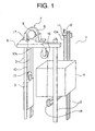
  • Fig. 1 is a perspective view of an elevator apparatus according to Embodiment Mode 1 of the present invention
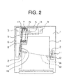
  • Fig. 2 is a plan view showing the elevator apparatus of Fig. 1.
  • a hoistway 1 installed in a hoistway 1 are a pair of car guide rails 2 and a pair of counterweight guide rails 3.
  • a car 4 is guided by the car guide rails 2 to be raised and lowered in the hoistway 1.
  • a counterweight 5 is arranged behind the car 4 and is guided by the counterweight guide rails 3 to be raised and lowered in the hoistway 1.
  • a straight line connecting the centers of the pair of car guide rails 2 extends parallel to the frontage direction of the car 4 and passes the center of gravity of the car 4. Further, a straight line connecting the centers of the pair of counterweight guide rails 3 also extends parallel to the frontage direction of the car 4.
  • a machine base 6 is secured in position in the vicinity of the upper end of one of the car guide rails 2 and the upper ends of the pair of counterweight guide rails 3.
  • a driving machine (hoist machine) 7 for raising and lowering the car 4 and the counterweight 5.
  • the driving machine 7 has a driving machine main body 8 including a motor portion and a brake portion, and a driving sheave 9 rotated by the driving machine main body 8.
  • the driving machine 7 is arranged such that a rotation shaft of the driving sheave 9 extends horizontally. Further, the driving machine 7 is arranged so as to overlap, in a vertical plane of projection, a corner portion at the back of the car 4 and the counterweight 5. Further, the driving machine 7 consists of a thin hoist machine whose diameter is larger than the axial dimension thereof.
  • the driving machine 7 is arranged such that the driving machine main body 8 is situated on the car 4 side and that the driving sheave 9 is substantially parallel and opposed to a hoistway wall opposed to a side surface of the car 4.
  • a plurality of main ropes 10 (only one of which is shown in the drawing) that suspend the car 4 and the counterweight 5 in the hoistway 1 are wrapped around the driving sheave 9.
  • a rope support portion 11 is secured in position in the vicinity of the upper end of the other car guide rail 2.
  • a first end 10a of each main rope 10 is connected to the rope support portion 11 through the intermediation of a car side rope stop 12.
  • a second end 10b of each main rope 10 is connected to the machine base 6 through the intermediation of a counterweight side rope stop 13.
  • a rotatable deflector sheave 16 for guiding the main ropes 10 from the driving sheave 9 to the car suspension sheaves 14.
  • the deflector sheave 16 is arranged such that its rotation shaft extends parallel to the rotation shaft of the driving sheave 9 and the deflection sheave 16 is arranged in a plane perpendicularly crossing the rotation shaft of the driving sheave 9 and including the driving sheave 9. That is, in a vertical plane of projection, the driving sheave 9 and the deflector sheave 16 are arranged in a straight line.
  • the main ropes 10 are wrapped around the car suspension sheaves 14, the deflector sheave 16, the driving sheave 9, and the counterweight suspension sheave 15 in the stated order to reach the second ends 10b. That is, the car 4 and the counterweight 5 are suspended in the 2:1 roping system.
  • the portions of the main ropes 10 extending from the counterweight suspension sheaves 14 to the car side rope stop 12 are arranged on the front side of the car guide rails 2.
  • the portions of the main ropes 10 extending from the counterweight suspension sheaves 14 to the deflector sheave 16 are arranged on the rear side of the car guide rails 2.
  • Fig. 3 is a front view of the driving machine 7 of Fig. 1
  • Fig. 4 is a plan view of the driving machine 7 of Fig. 1.
  • a pair of brackets 17 opposed to each other are fixed to the machine base 6.
  • the driving machine 7 is arranged between these brackets 17.
  • a plurality of bottom vibration-isolating members 18 are provided between the bottom of the driving machine 7 and the machine base 6.
  • side vibration-isolating members 19 are provided between the driving machine 7 and the brackets 17.
  • These vibration-isolating members 18 and 19 are formed of a resilient material such as rubber.
  • this machine-room-less elevator apparatus it is possible to efficiently utilize the space inside the hoistway 1 and to minimize the sectional area of the hoistway 1. Further, since the driving machine 7 is arranged such that the driving machine main body 8 is situated on the car 4 side, maintenance operation on the motor portion and the brake portion contained in the driving machine main body 8 can be easily performed from the top of the car 4, and it is possible to sufficiently secure the requisite space for the maintenance operation.
  • the mounting of the driving machine 7 and the deflector sheave 16 to the same machine base 6 leads to a simple structure and facilitates the installing operation.
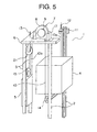
  • Fig. 5 is a perspective view of an elevator apparatus according to Embodiment Mode 2 of the present invention
  • Fig. 6 is a plan view of the elevator apparatus of Fig. 5.
  • the driving machine 7 is arranged so as to overlap a side portion of the car 4 in a vertical plane of projection.
  • Mounted to themachine base 6 is a rotatable deflector sheave 21 guiding the main ropes 10 from the driving sheave 9 to the counterweight suspension sheave 15.
  • the deflector sheave 21 is arranged such that its rotation shaft extends parallel to the rotation shaft of the driving sheave 9 and that the deflector sheave 21 is arranged in a plane perpendicularly crossing the rotation shaft of the driving sheave 9 and including the driving sheave 9. That is, in a vertical plane of projection, the driving sheave 9 and the deflector sheave 21 are arranged in a straight line. otherwise, this embodiment mode is of the same construction as Embodiment Mode 1.
  • this machine-room-less elevator apparatus it is possible to efficiently utilize the space inside the hoistway 1 and to minimize the sectional area of the hoistway 1. Further, by adjusting the position of the driving machine 7 according to the size of the car 4, it is possible to effect adjustment easily such that the main ropes 10 pass near the center of gravity of the car 4. As a result, it is possible to reduce the load burden on the car guide rails 2 and the car side rope stop 12 imposed due to the self weight of the car 4 and unbalance in the live load on the car 4.
  • Fig. 7 is a perspective view of an elevator apparatus according to Embodiment Mode 3 of the present invention.
  • first and second counterweight suspension sheaves 22a and 22b are provided on top of the counterweight 5 .
  • this embodiment mode is of the same construction as Embodiment Mode 1.
  • the main ropes 10, extending upwards from the counterweight sheaves 22a and 22b can be arranged vertically, thereby raising and lowering the counterweight 5 in a stable manner.
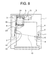
  • Fig. 8 is a plan view of an elevator apparatus according to Embodiment Mode 4 of the present invention.
  • a driving machine (hoist machine) 23 is mounted on the machine base 6.
  • the driving machine 23 has a driving machine main body 24 including a motor portion and a brake portion, and a driving sheave 25 rotated by the driving machine main body 24.
  • the driving machine 23 consists of a cylindrical hoist machine whose axial dimension is larger than the diameter thereof. Otherwise, this embodiment mode is of the same construction as Embodiment Mode 1.
  • the machine base 6 is supported by the guide rails 2 and 3
  • the machine base may also be supported by a structure in the hoistway. In this case, it is possible to relieve the load applied to the guide rails and to simplify the structure of the guide rails.
  • deflector sheave is arranged between the driving sheave and the car suspension sheave or the counterweight suspension sheave
  • deflector sheaves respectively between the driving sheave and the car suspension sheave and between the driving sheave and the counterweight suspension sheave. That is, it is also possible to use a plurality of deflector sheaves.
Landscapes

  • Engineering & Computer Science (AREA)
  • Civil Engineering (AREA)
  • Mechanical Engineering (AREA)
  • Structural Engineering (AREA)
  • Lift-Guide Devices, And Elevator Ropes And Cables (AREA)
  • Cage And Drive Apparatuses For Elevators (AREA)

Abstract

Provided is an elevator apparatus including a deflector sheave that is arranged in an upper portion of the hoistway and guides a main rope from a driving sheave to a car suspension sheave. The driving machine is arranged so as to overlap a car in a vertical plane of projection, and the deflector sheave is arranged such that the rotation shaft of the deflector sheave extends parallel to the rotation shaft of the driving sheave, with the deflector sheave being arranged in a plane perpendicularly crossing the rotation shaft of the driving sheave and including the driving sheave.

Description

Technical Field
The present invention relates to an elevator apparatus in which a driving machine is arranged in an upper portion of the hoistway.
Background Art
JP 10-139321 A discloses a conventional example of a so-called machine-room-less type elevator apparatus in which no machine room is provided in an upper portion of the hoistway and in which a driving machine is provided in the upper portion of the hoistway. As compared with the case in which a machine room is separately provided in the upper portion of the hoistway, this type of elevator apparatus is advantageous in that the height of the building can be reduced. However, in this type of elevator apparatus, it is necessary to secure a space for arranging the driving machine in the upper portion of the hoistway. Thus, it is desired that the space inside the hoistway be utilized as efficiently as possible.
Disclosure of the Invention
The present invention has been made with a view toward solving the above problem in the prior art. It is an object of the present invention to provide an elevator apparatus which makes it possible to efficiently utilize the space inside the hoistway and to minimize the sectional area of the hoistway.
To this end, according to one aspect of the present invention, there is provided an elevator apparatus comprising: a hoistway; a car raised and lowered in the hoistway; a car suspension sheave provided at the car; a counterweight arranged behind the car and raised and lowered in the hoistway; a counterweight suspension sheave provided on the counterweight; a driving machine for raising and lowering the car and the counterweight, which has a driving machine main body arranged in an upper portion of the hoistway and a driving sheave rotated by the driving machine main body, the driving sheave having a rotation shaft arranged so as to extend horizontally; a main rope having a first end portion and a second end portion that are connected to the upper portion of the hoistway, the main rope being wrapped around the car suspension sheave, the driving sheave, and the counterweight suspension sheave to suspend the car and the counterweight in the hoistway; and at least one deflector sheave which is arranged in the upper portion of the hoistway and around which the main rope is wound, the deflector sheave guiding the main rope from the driving sheave to at least one of the car suspension sheave and the counterweight suspension sheave, wherein the driving machine is arranged so as to overlap the car in a vertical plane of projection, and wherein the deflector sheave is arranged such that its rotation shaft extends parallel to the rotation shaft of the driving sheave, with the deflector sheave being arranged in a plane perpendicularly crossing the rotation shaft of the driving sheave and including the driving sheave.
Brief Description of the Drawings
  • Fig. 1 a perspective view of an elevator apparatus according to Embodiment Mode 1 of the present invention;
  • Fig. 2 is a plan view of the elevator apparatus of Fig. 1;
  • Fig. 3 is a front view of a driving machine of Fig. 1;
  • Fig. 4 is a plan view of the driving machine of Fig. 1;
  • Fig. 5 a perspective view of an elevator apparatus according to Embodiment Mode 2 of the present invention;
  • Fig. 6 is a plan view of the elevator apparatus of Fig. 5;
  • Fig. 7 is a perspective view of an elevator apparatus according to Embodiment Mode 3 of the present invention; and
  • Fig. 8 is a plan view of an elevator apparatus according to Embodiment Mode 4 of the present invention.
  • Best Mode for carrying out the Invention
    Hereinafter, preferred embodiment modes of the present invention will be described with reference to the drawings.
    Embodiment Mode 1
    Fig. 1 is a perspective view of an elevator apparatus according to Embodiment Mode 1 of the present invention, and Fig. 2 is a plan view showing the elevator apparatus of Fig. 1.
    In the drawings, installed in a hoistway 1 are a pair of car guide rails 2 and a pair of counterweight guide rails 3. A car 4 is guided by the car guide rails 2 to be raised and lowered in the hoistway 1. A counterweight 5 is arranged behind the car 4 and is guided by the counterweight guide rails 3 to be raised and lowered in the hoistway 1.
    In a vertical plane of projection, a straight line connecting the centers of the pair of car guide rails 2 extends parallel to the frontage direction of the car 4 and passes the center of gravity of the car 4. Further, a straight line connecting the centers of the pair of counterweight guide rails 3 also extends parallel to the frontage direction of the car 4.
    A machine base 6 is secured in position in the vicinity of the upper end of one of the car guide rails 2 and the upper ends of the pair of counterweight guide rails 3. Mounted on the machine base 6 is a driving machine (hoist machine) 7 for raising and lowering the car 4 and the counterweight 5. The driving machine 7 has a driving machine main body 8 including a motor portion and a brake portion, and a driving sheave 9 rotated by the driving machine main body 8.
    The driving machine 7 is arranged such that a rotation shaft of the driving sheave 9 extends horizontally. Further, the driving machine 7 is arranged so as to overlap, in a vertical plane of projection, a corner portion at the back of the car 4 and the counterweight 5. Further, the driving machine 7 consists of a thin hoist machine whose diameter is larger than the axial dimension thereof.
    Further, the driving machine 7 is arranged such that the driving machine main body 8 is situated on the car 4 side and that the driving sheave 9 is substantially parallel and opposed to a hoistway wall opposed to a side surface of the car 4.
    A plurality of main ropes 10 (only one of which is shown in the drawing) that suspend the car 4 and the counterweight 5 in the hoistway 1 are wrapped around the driving sheave 9. A rope support portion 11 is secured in position in the vicinity of the upper end of the other car guide rail 2. A first end 10a of each main rope 10 is connected to the rope support portion 11 through the intermediation of a car side rope stop 12. A second end 10b of each main rope 10 is connected to the machine base 6 through the intermediation of a counterweight side rope stop 13.
    Under the car 4, there are provided a pair of suspension sheaves 14 around which the main ropes 10 are wrapped. On top of the counterweight 5, there is provided a counterweight suspension sheave 15 around which the main ropes 10 are wrapped.
    Mounted to the machine base 6 is a rotatable deflector sheave 16 for guiding the main ropes 10 from the driving sheave 9 to the car suspension sheaves 14. The deflector sheave 16 is arranged such that its rotation shaft extends parallel to the rotation shaft of the driving sheave 9 and the deflection sheave 16 is arranged in a plane perpendicularly crossing the rotation shaft of the driving sheave 9 and including the driving sheave 9. That is, in a vertical plane of projection, the driving sheave 9 and the deflector sheave 16 are arranged in a straight line.
    Extending from their first ends 10a, the main ropes 10 are wrapped around the car suspension sheaves 14, the deflector sheave 16, the driving sheave 9, and the counterweight suspension sheave 15 in the stated order to reach the second ends 10b. That is, the car 4 and the counterweight 5 are suspended in the 2:1 roping system.
    The portions of the main ropes 10 extending from the counterweight suspension sheaves 14 to the car side rope stop 12 are arranged on the front side of the car guide rails 2. The portions of the main ropes 10 extending from the counterweight suspension sheaves 14 to the deflector sheave 16 are arranged on the rear side of the car guide rails 2. As a result, the car 4 is suspended at the position of its center of gravity.
    Fig. 3 is a front view of the driving machine 7 of Fig. 1, and Fig. 4 is a plan view of the driving machine 7 of Fig. 1. In the drawings, a pair of brackets 17 opposed to each other are fixed to the machine base 6. The driving machine 7 is arranged between these brackets 17. A plurality of bottom vibration-isolating members 18 are provided between the bottom of the driving machine 7 and the machine base 6. Further, side vibration-isolating members 19 are provided between the driving machine 7 and the brackets 17. These vibration-isolating members 18 and 19 are formed of a resilient material such as rubber.
    In the above-described layout of this machine-room-less elevator apparatus, it is possible to efficiently utilize the space inside the hoistway 1 and to minimize the sectional area of the hoistway 1. Further, since the driving machine 7 is arranged such that the driving machine main body 8 is situated on the car 4 side, maintenance operation on the motor portion and the brake portion contained in the driving machine main body 8 can be easily performed from the top of the car 4, and it is possible to sufficiently secure the requisite space for the maintenance operation.
    Further, due to the provision of the bottom vibration-isolating members 18 between the bottom of the driving machine 7 and the machine base 6, it is possible to restrain transmission of the vertical vibration of the driving machine 7 to the car 4 and the building. Further, due to the provision of the side vibration-isolating members 19 between the driving machine 7 and the brackets 17, it is possible to restrain transmission of the horizontal vibration of the driving machine 7 to the car 4 and the building.
    Furthermore, the mounting of the driving machine 7 and the deflector sheave 16 to the same machine base 6 leads to a simple structure and facilitates the installing operation.
    Embodiment Mode 2
    Next, Fig. 5 is a perspective view of an elevator apparatus according to Embodiment Mode 2 of the present invention, and Fig. 6 is a plan view of the elevator apparatus of Fig. 5. In the drawings, the driving machine 7 is arranged so as to overlap a side portion of the car 4 in a vertical plane of projection. Mounted to themachine base 6 is a rotatable deflector sheave 21 guiding the main ropes 10 from the driving sheave 9 to the counterweight suspension sheave 15.
    The deflector sheave 21 is arranged such that its rotation shaft extends parallel to the rotation shaft of the driving sheave 9 and that the deflector sheave 21 is arranged in a plane perpendicularly crossing the rotation shaft of the driving sheave 9 and including the driving sheave 9. That is, in a vertical plane of projection, the driving sheave 9 and the deflector sheave 21 are arranged in a straight line. otherwise, this embodiment mode is of the same construction as Embodiment Mode 1.
    In the above-described layout of this machine-room-less elevator apparatus, it is possible to efficiently utilize the space inside the hoistway 1 and to minimize the sectional area of the hoistway 1. Further, by adjusting the position of the driving machine 7 according to the size of the car 4, it is possible to effect adjustment easily such that the main ropes 10 pass near the center of gravity of the car 4. As a result, it is possible to reduce the load burden on the car guide rails 2 and the car side rope stop 12 imposed due to the self weight of the car 4 and unbalance in the live load on the car 4.
    Embodiment Mode 3
    Next, Fig. 7 is a perspective view of an elevator apparatus according to Embodiment Mode 3 of the present invention. In the drawing, provided on top of the counterweight 5 are first and second counterweight suspension sheaves 22a and 22b around which the main ropes 10 are wrapped. Otherwise, this embodiment mode is of the same construction as Embodiment Mode 1.
    By thus using two counterweight sheaves 22a and 22b, the main ropes 10, extending upwards from the counterweight sheaves 22a and 22b, can be arranged vertically, thereby raising and lowering the counterweight 5 in a stable manner.
    Embodiment Mode 4
    Next, Fig. 8 is a plan view of an elevator apparatus according to Embodiment Mode 4 of the present invention. In the drawing, a driving machine (hoist machine) 23 is mounted on the machine base 6. The driving machine 23 has a driving machine main body 24 including a motor portion and a brake portion, and a driving sheave 25 rotated by the driving machine main body 24. The driving machine 23 consists of a cylindrical hoist machine whose axial dimension is larger than the diameter thereof. Otherwise, this embodiment mode is of the same construction as Embodiment Mode 1.
    Even in the case in which this driving machine 23 consisting of a cylindrical hoist machine is used, it is possible to efficiently utilize the space inside the hoistway 1 and to minimize the sectional area of the hoistway 1.
    While in the above examples the machine base 6 is supported by the guide rails 2 and 3, the machine base may also be supported by a structure in the hoistway. In this case, it is possible to relieve the load applied to the guide rails and to simplify the structure of the guide rails.
    Further, while in the above examples the deflector sheave is arranged between the driving sheave and the car suspension sheave or the counterweight suspension sheave, it is also possible to arrange deflector sheaves respectively between the driving sheave and the car suspension sheave and between the driving sheave and the counterweight suspension sheave. That is, it is also possible to use a plurality of deflector sheaves.
    Claims (4)

    1. An elevator apparatus comprising:
      a hoistway;
      a car raised and lowered in the hoistway;
      a car suspension sheave provided at the car;
      a counterweight arranged behind the car and raised and lowered in the hoistway;
      a counterweight suspension sheave provided on the counterweight;
      a driving machine for raising and lowering the car and the counterweight, which has a driving machine main body arranged in an upper portion of the hoistway and a driving sheave rotated by the driving machine main body, the driving sheave having a rotation shaft arranged so as to extend horizontally;
      a main rope having a first end portion and a second end portion that are connected to the upper portion of the hoistway, the main rope being wrapped around the car suspension sheave, the driving sheave, and the counterweight suspension sheave to suspend the car and the counterweight in the hoistway; and
      at least one deflector sheave which is arranged in the upper portion of the hoistway and around which the main rope is wound, the deflector sheave guiding the main rope from the driving sheave to at least one of the car suspension sheave and the counterweight suspension sheave,
         wherein the driving machine is arranged so as to overlap the car in a vertical plane of projection, and wherein the deflector sheave is arranged such that its rotation shaft extends parallel to the rotation shaft of the driving sheave, with the deflector sheave being arranged in a plane perpendicularly crossing the rotation shaft of the driving sheave and including the driving sheave.
    2. An elevator apparatus according to Claim 1, wherein the driving machine is arranged so as to overlap a corner portion at the back of the car and the counterweight in a vertical plane of projection, and wherein the deflector sheave guides the main rope from the driving sheave to the car suspension sheave.
    3. An elevator apparatus according to Claim 1, wherein the driving machine is arranged so as to overlap a side portion of the car in a vertical plane of projection, and wherein the deflector sheave guides the main rope from the driving sheave to the counterweight suspension sheave.
    4. An elevator apparatus according to Claim 1, wherein the driving machine and the deflector sheave are supported by a common machine base secured in position in the upper portion of the hoistway.
    EP02720637A 2002-04-30 2002-04-30 ELEVATOR Withdrawn EP1500620A4 (en)

    Applications Claiming Priority (1)

    Application Number Priority Date Filing Date Title
    PCT/JP2002/004329 WO2003093155A1 (en) 2002-04-30 2002-04-30 Elevator

    Publications (2)

    Publication Number Publication Date
    EP1500620A1 true EP1500620A1 (en) 2005-01-26
    EP1500620A4 EP1500620A4 (en) 2010-04-14

    Family

    ID=29287941

    Family Applications (1)

    Application Number Title Priority Date Filing Date
    EP02720637A Withdrawn EP1500620A4 (en) 2002-04-30 2002-04-30 ELEVATOR

    Country Status (5)

    Country Link
    EP (1) EP1500620A4 (en)
    JP (1) JPWO2003093155A1 (en)
    KR (1) KR20040010737A (en)
    CN (1) CN1649790A (en)
    WO (1) WO2003093155A1 (en)

    Cited By (1)

    * Cited by examiner, † Cited by third party
    Publication number Priority date Publication date Assignee Title
    WO2013110861A1 (en) * 2012-01-27 2013-08-01 Kone Corporation Apparatus for fixing a hoisting machine of an elevator and a fixing arrangement

    Families Citing this family (3)

    * Cited by examiner, † Cited by third party
    Publication number Priority date Publication date Assignee Title
    JP6082641B2 (en) * 2013-04-05 2017-02-15 株式会社日立製作所 Elevator equipment
    JP6849748B2 (en) * 2019-07-19 2021-03-31 東芝エレベータ株式会社 Elevator main rope steady rest device
    CN113928958A (en) * 2021-09-28 2022-01-14 日立电梯(中国)有限公司 Multi-suspension-ratio elevator device with machine room

    Family Cites Families (3)

    * Cited by examiner, † Cited by third party
    Publication number Priority date Publication date Assignee Title
    ES2227012T3 (en) * 1996-11-11 2005-04-01 Inventio Ag ELEVATOR INSTALLATION WITH MOTOR UNIT DISPOSED IN THE ELEVATOR BOX.
    JP2001080843A (en) * 1999-09-14 2001-03-27 Mitsubishi Electric Corp Elevator equipment
    JP2002080178A (en) * 2000-09-04 2002-03-19 Mitsubishi Electric Corp Elevator equipment

    Cited By (3)

    * Cited by examiner, † Cited by third party
    Publication number Priority date Publication date Assignee Title
    WO2013110861A1 (en) * 2012-01-27 2013-08-01 Kone Corporation Apparatus for fixing a hoisting machine of an elevator and a fixing arrangement
    EP2807106A4 (en) * 2012-01-27 2015-11-25 Kone Corp APPARATUS FOR FIXING AN ELEVATOR LIFTING MACHINE AND FIXING ARRANGEMENT
    US10035682B2 (en) 2012-01-27 2018-07-31 Kone Corporation Apparatus for fixing a hoisting machine of an elevator and a fixing arrangement

    Also Published As

    Publication number Publication date
    KR20040010737A (en) 2004-01-31
    CN1649790A (en) 2005-08-03
    EP1500620A4 (en) 2010-04-14
    JPWO2003093155A1 (en) 2005-09-08
    WO2003093155A1 (en) 2003-11-13

    Similar Documents

    Publication Publication Date Title
    JP5805212B2 (en) Elevator equipment
    US7117977B2 (en) Elevator apparatus including car with suspending pulley devices on opposite sides of the car
    US20110108366A1 (en) Elevator apparatus
    JP2005029344A (en) Elevator without machine room
    EP1302430B1 (en) Elevator device
    JP4882195B2 (en) Elevator equipment
    JP2002080178A (en) Elevator equipment
    JP2009073658A (en) Elevator without machine room
    EP1481935A1 (en) Elevaltor apparatus
    JP4549616B2 (en) Elevator equipment
    JP2014009044A (en) Elevator device
    US7562745B2 (en) Elevator with an operation space in a center of a machine room
    CN104428235A (en) Elevator device
    EP1500620A1 (en) Elevator
    JPWO2004050528A1 (en) Elevator equipment
    JP2006264862A (en) Elevator without machine room
    EP1717185B1 (en) Elevator
    JPWO2005082767A1 (en) Elevator equipment
    JP4770241B2 (en) Elevator equipment
    JP2005306513A (en) Elevator equipment
    WO2004028948A1 (en) Elevator equipment
    EP1571113A1 (en) Elevator equipment
    JP5570602B2 (en) Elevator equipment
    EP1736431B1 (en) Elevator apparatus
    WO2025083743A1 (en) Elevator

    Legal Events

    Date Code Title Description
    PUAI Public reference made under article 153(3) epc to a published international application that has entered the european phase

    Free format text: ORIGINAL CODE: 0009012

    17P Request for examination filed

    Effective date: 20031016

    AK Designated contracting states

    Kind code of ref document: A1

    Designated state(s): AT BE CH CY DE DK ES FI FR GB GR IE IT LI LU MC NL PT SE TR

    AX Request for extension of the european patent

    Extension state: AL LT LV MK RO SI

    RAP1 Party data changed (applicant data changed or rights of an application transferred)

    Owner name: MITSUBISHI DENKI KABUSHIKI KAISHA

    A4 Supplementary search report drawn up and despatched

    Effective date: 20100315

    17Q First examination report despatched

    Effective date: 20100615

    STAA Information on the status of an ep patent application or granted ep patent

    Free format text: STATUS: THE APPLICATION IS DEEMED TO BE WITHDRAWN

    18D Application deemed to be withdrawn

    Effective date: 20101030