EP1500510A1 - Thermally induced phase separation to recover ink-jet pen - Google Patents
Thermally induced phase separation to recover ink-jet pen Download PDFInfo
- Publication number
- EP1500510A1 EP1500510A1 EP04009547A EP04009547A EP1500510A1 EP 1500510 A1 EP1500510 A1 EP 1500510A1 EP 04009547 A EP04009547 A EP 04009547A EP 04009547 A EP04009547 A EP 04009547A EP 1500510 A1 EP1500510 A1 EP 1500510A1
- Authority
- EP
- European Patent Office
- Prior art keywords
- ink
- organic surfactant
- jet
- surfactant phase
- phase
- Prior art date
- Legal status (The legal status is an assumption and is not a legal conclusion. Google has not performed a legal analysis and makes no representation as to the accuracy of the status listed.)
- Granted
Links
- 238000002145 thermally induced phase separation Methods 0.000 title 1
- 239000004094 surface-active agent Substances 0.000 claims abstract description 65
- 238000010304 firing Methods 0.000 claims abstract description 33
- 238000000034 method Methods 0.000 claims abstract description 22
- 239000003086 colorant Substances 0.000 claims abstract description 19
- 230000001681 protective effect Effects 0.000 claims abstract description 18
- 238000010438 heat treatment Methods 0.000 claims abstract description 13
- 238000001704 evaporation Methods 0.000 claims abstract description 9
- 230000008020 evaporation Effects 0.000 claims abstract description 9
- 239000012071 phase Substances 0.000 claims description 52
- 239000002904 solvent Substances 0.000 claims description 19
- 239000010410 layer Substances 0.000 claims description 12
- -1 siloxanes Chemical class 0.000 claims description 11
- 239000000049 pigment Substances 0.000 claims description 9
- 229930195733 hydrocarbon Natural products 0.000 claims description 8
- 150000002430 hydrocarbons Chemical class 0.000 claims description 8
- 238000007639 printing Methods 0.000 claims description 8
- 229920003171 Poly (ethylene oxide) Polymers 0.000 claims description 6
- KPUWHANPEXNPJT-UHFFFAOYSA-N disiloxane Chemical class [SiH3]O[SiH3] KPUWHANPEXNPJT-UHFFFAOYSA-N 0.000 claims description 6
- 239000003921 oil Substances 0.000 claims description 6
- 239000004215 Carbon black (E152) Substances 0.000 claims description 5
- IAYPIBMASNFSPL-UHFFFAOYSA-N Ethylene oxide Chemical class C1CO1 IAYPIBMASNFSPL-UHFFFAOYSA-N 0.000 claims description 5
- 150000008282 halocarbons Chemical class 0.000 claims description 5
- 239000012074 organic phase Substances 0.000 claims description 5
- 150000003839 salts Chemical class 0.000 claims description 5
- GOOHAUXETOMSMM-UHFFFAOYSA-N Propylene oxide Chemical class CC1CO1 GOOHAUXETOMSMM-UHFFFAOYSA-N 0.000 claims description 4
- 229920001451 polypropylene glycol Polymers 0.000 claims description 4
- 239000011241 protective layer Substances 0.000 claims description 3
- 239000000976 ink Substances 0.000 description 76
- XLYOFNOQVPJJNP-UHFFFAOYSA-N water Substances O XLYOFNOQVPJJNP-UHFFFAOYSA-N 0.000 description 9
- 239000000975 dye Substances 0.000 description 4
- 238000010792 warming Methods 0.000 description 4
- PEDCQBHIVMGVHV-UHFFFAOYSA-N Glycerine Chemical compound OCC(O)CO PEDCQBHIVMGVHV-UHFFFAOYSA-N 0.000 description 3
- 238000011084 recovery Methods 0.000 description 3
- 239000002202 Polyethylene glycol Substances 0.000 description 2
- 125000000217 alkyl group Chemical group 0.000 description 2
- 239000007864 aqueous solution Substances 0.000 description 2
- 230000004888 barrier function Effects 0.000 description 2
- 229910052799 carbon Inorganic materials 0.000 description 2
- 239000001042 pigment based ink Substances 0.000 description 2
- 229920001223 polyethylene glycol Polymers 0.000 description 2
- 229920000642 polymer Polymers 0.000 description 2
- 238000000926 separation method Methods 0.000 description 2
- 239000000243 solution Substances 0.000 description 2
- 239000000126 substance Substances 0.000 description 2
- VZGDMQKNWNREIO-UHFFFAOYSA-N tetrachloromethane Chemical compound ClC(Cl)(Cl)Cl VZGDMQKNWNREIO-UHFFFAOYSA-N 0.000 description 2
- WKBOTKDWSSQWDR-UHFFFAOYSA-N Bromine atom Chemical compound [Br] WKBOTKDWSSQWDR-UHFFFAOYSA-N 0.000 description 1
- ZAMOUSCENKQFHK-UHFFFAOYSA-N Chlorine atom Chemical compound [Cl] ZAMOUSCENKQFHK-UHFFFAOYSA-N 0.000 description 1
- PXGOKWXKJXAPGV-UHFFFAOYSA-N Fluorine Chemical compound FF PXGOKWXKJXAPGV-UHFFFAOYSA-N 0.000 description 1
- 239000000654 additive Substances 0.000 description 1
- 150000001298 alcohols Chemical class 0.000 description 1
- 239000008346 aqueous phase Substances 0.000 description 1
- 125000004429 atom Chemical group 0.000 description 1
- 230000009286 beneficial effect Effects 0.000 description 1
- 230000015572 biosynthetic process Effects 0.000 description 1
- 238000009835 boiling Methods 0.000 description 1
- GDTBXPJZTBHREO-UHFFFAOYSA-N bromine Substances BrBr GDTBXPJZTBHREO-UHFFFAOYSA-N 0.000 description 1
- 229910052794 bromium Inorganic materials 0.000 description 1
- 229910052801 chlorine Inorganic materials 0.000 description 1
- 239000000460 chlorine Substances 0.000 description 1
- 125000001309 chloro group Chemical group Cl* 0.000 description 1
- 239000006184 cosolvent Substances 0.000 description 1
- FTZLWXQKVFFWLY-UHFFFAOYSA-L disodium;2,5-dichloro-4-[3-methyl-5-oxo-4-[(4-sulfonatophenyl)diazenyl]-4h-pyrazol-1-yl]benzenesulfonate Chemical compound [Na+].[Na+].CC1=NN(C=2C(=CC(=C(Cl)C=2)S([O-])(=O)=O)Cl)C(=O)C1N=NC1=CC=C(S([O-])(=O)=O)C=C1 FTZLWXQKVFFWLY-UHFFFAOYSA-L 0.000 description 1
- 239000001041 dye based ink Substances 0.000 description 1
- 230000000694 effects Effects 0.000 description 1
- 239000003792 electrolyte Substances 0.000 description 1
- 239000000839 emulsion Substances 0.000 description 1
- 238000005516 engineering process Methods 0.000 description 1
- 229910052731 fluorine Inorganic materials 0.000 description 1
- 239000011737 fluorine Substances 0.000 description 1
- 125000001153 fluoro group Chemical group F* 0.000 description 1
- NBVXSUQYWXRMNV-UHFFFAOYSA-N fluoromethane Chemical compound FC NBVXSUQYWXRMNV-UHFFFAOYSA-N 0.000 description 1
- 239000003906 humectant Substances 0.000 description 1
- 230000002209 hydrophobic effect Effects 0.000 description 1
- 229910017053 inorganic salt Inorganic materials 0.000 description 1
- AJDUTMFFZHIJEM-UHFFFAOYSA-N n-(9,10-dioxoanthracen-1-yl)-4-[4-[[4-[4-[(9,10-dioxoanthracen-1-yl)carbamoyl]phenyl]phenyl]diazenyl]phenyl]benzamide Chemical compound O=C1C2=CC=CC=C2C(=O)C2=C1C=CC=C2NC(=O)C(C=C1)=CC=C1C(C=C1)=CC=C1N=NC(C=C1)=CC=C1C(C=C1)=CC=C1C(=O)NC1=CC=CC2=C1C(=O)C1=CC=CC=C1C2=O AJDUTMFFZHIJEM-UHFFFAOYSA-N 0.000 description 1
- 239000003960 organic solvent Substances 0.000 description 1
- 239000002245 particle Substances 0.000 description 1
- 238000005191 phase separation Methods 0.000 description 1
- 239000007787 solid Substances 0.000 description 1
- 230000007928 solubilization Effects 0.000 description 1
- 238000005063 solubilization Methods 0.000 description 1
- 230000003381 solubilizing effect Effects 0.000 description 1
- 239000010409 thin film Substances 0.000 description 1
- 239000001043 yellow dye Substances 0.000 description 1
Images
Classifications
-
- B—PERFORMING OPERATIONS; TRANSPORTING
- B41—PRINTING; LINING MACHINES; TYPEWRITERS; STAMPS
- B41J—TYPEWRITERS; SELECTIVE PRINTING MECHANISMS, i.e. MECHANISMS PRINTING OTHERWISE THAN FROM A FORME; CORRECTION OF TYPOGRAPHICAL ERRORS
- B41J2/00—Typewriters or selective printing mechanisms characterised by the printing or marking process for which they are designed
- B41J2/005—Typewriters or selective printing mechanisms characterised by the printing or marking process for which they are designed characterised by bringing liquid or particles selectively into contact with a printing material
- B41J2/01—Ink jet
- B41J2/135—Nozzles
- B41J2/165—Prevention or detection of nozzle clogging, e.g. cleaning, capping or moistening for nozzles
Definitions
- the field relates to forming a protective cushion to slow down evaporation and prevent clogging in an inactive ink-jet printhead.
- the ink firing chamber of the pen can be heated and the inks can be repeatedly spit in a spittoon, with intermittent wiping of the pen (sometimes, with a solvent such as glycerol or polyethylene glycol (PEG)).
- the pen can be actively primed by a pump.
- adding co-solvents (humectants) and surfactants helps to slow down crusting of ink components by reducing evaporation, such cosolvents and surfactants occasionally even forming a soft gel plug of the solvent at the nozzle. All of these ways of dealing with the pen recovery problem are either time-consuming, not consistently effective or both.
- the present invention relates to a method of forming a protective cushion to slow down evaporation and prevent clogging in an inactive ink-jet printhead, the inactive ink-jet printhead comprised of at least one ink firing chamber having an opening to at least one nozzle, the method comprising the steps of:
- the present invention also relates to a system to slow down evaporation and prevent dogging in an inactive ink-jet printhead by forming a protective cushion covering an opening of at least one ink-jet nozzle in at least one ink firing chamber, the at least one ink firing chamber comprising:
- the present inventor has discovered a way to induce the formation of an organic cushion covering the nozzle in an ink firing chamber by the separation of the ink vehicle from the ink colorant in either dye-based or pigment-based ink. This is done by the abrupt heating up of the ink firing chamber to the point at which the ink vehicle phase separates into two layers.
- the lower layer more dense than the upper layer, is formulated in such a way that it shows poor solubility for crusting components in the inks and has a low viscosity and vapor pressure. It thus serves as a protective layer or cushion that will slow down the evaporation from the pen, as well as, in the case of pigment-based inks, stop pigment from settling in the bottom layer.
- clouding temperature can be adjusted by adding co-surfactants, co-solvents, oils and electrolytes (M. Kahlweit R. Strey, Angew. Chem., Int. Ed. Engl., v. 24, p 654, 1985).
- “Clouded” solutions of surfactants tend to separate with time into two distinct layers. Whether or not the surfactant phase forms on the top or on the bottom depends on the relative densities of the surfactant and water. Typically, hydrocarbon surfactants are less dense than water and the surfactant phase forms on the top. However, if the surfactant contains atoms with higher atomic weight, such as fluorine, chlorine or bromine, the surfactant layer will form on the bottom.
- the density of the surfactant phase can be additionally adjusted by solubilizing some amount of an oil in the surfactant. Again, hydrocarbon oils tend to have a density that is lower than that of water.
- halocarbons such as chloro, fluoro and bromocarbons tend to be more dense than water and can increase the density of the surfactant phase.
- the solubility of dyes/pigments in the surfactant phase should be carefully adjusted in such a way that the colorant is depleted from the surfactant phase.
- the dyes/pigments, as well as inorganic salt additives used in ink-jet are water soluble and are expected to be depleted from the surfactant phase that overall has a more hydrophobic environment than the aqueous solution.
- the ink drop ejection in the ink firing chamber is caused by the abrupt heating and boiling of the ink on a resistor. It also has been known in the art that the resistors can be utilized for increasing the temperature in the firing chamber without causing the drop ejection, known as pulse warming.
- Pulse warming is a technique used to warm the printhead temperature before printing and maintain it during printing thereby ensuring consistent drop volume. Pulse warming uses the same hardware that is used to fire the printhead during printing with one important difference ⁇ the pulse width is too small to cause ink to eject, as described in e.g., EP 1093918A2.
- ink-jet inks that tend to cloud at elevated temperatures.
- color inks used in 700- 800 series Deskjet printers produced by Hewlett Packard cloud between about 40 and 95 °C. Clouding of inks at these temperatures as such does not preclude them from being used in thermal ink-jet, insofar as the normal temperature of the firing chamber remains below the cloud point. This is despite the fact that inks can get as hot as 200°C without clouding when the turn on energy (TOE) is applied to the resistor in the ink chamber during the firing event.
- TOE turn on energy
- the firing event does not cause a clouding problem, because clouding does not have enough time to develop during the interval that the ink chamber temperature is at 200°C.
- Such ink clouding at 40-95°C can be artificially induced by pulse-warming the ink chamber for several seconds. This should be avoided during the normal pen cycle .
- the inventor has found that sending voltage below the turn-on energy to the resistor for several seconds to obtain an ink chamber temperature of 40-95°C, and in a preferred embodiment, 60-80°C, induces the separation of ink-jet ink to form a protective cushion of the organic surfactant phase of the ink solvents which covers the inner opening of the nozzle.
- This protective cushion on the nozzle prevents evaporation and crusting during the time the inkjet printhead is inactive and can be spit out of the nozzle when printing activity of the printhead resumes.
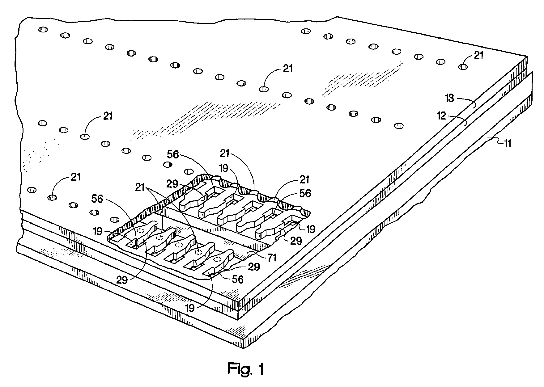
- Figure 1 is a schematic partially broken away perspective view of a non-limiting embodiment of an inkjet printhead, specifically showing the structure of an ink chamber including various structures related to the present invention.
- the ink chambers 19 are more particularly disposed over respective ink firing heater resistors 56, and each ink chamber 19 is defined by interconnected edges and walls of a chamber opening formed in the barrier layer 12 which is laminated to the thin film substructure 11.
- the ink channels 29 are defined by further openings formed in the barrier layer 12, and are integrally joined to respective ink firing chambers 19.
- the ink channels 29 open towards a feed edge of an adjacent ink feed slot 71 and receive ink from such ink feed slot.
- the orifice plate 13 includes orifices or nozzles 21 disposed over respective ink chambers 19, such that each ink firing heater resistor 56, an associated ink chamber 19, and an associated orifice 21 are aligned.
- an inkjet printer is built so that if the user opens the printer lid or the pen compartment latch, it activates a switch in the printhead.
- the switch switches on the resistors in the ink chambers.
- the resistors heat up and induce a phase separation of the ink in the ink chamber.
- the low vapor pressure solvent settles down at the nozzle bore and forms a protective "cushion" that is substantially devoid of the crusting components of the ink.
- an inkjet printer is built so that if the pen is passive for some time, e.g., 30 minutes of sitting on the cap without printing, the printer heats up the pen and the makes the organic solvent "cushion" at the bottom of the nozzle.
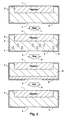
- Figure 2 shows four different stages in a side view of an ink firing chamber 2 in the present invention.
- the resistor 1 connected to the top inside surface of the chamber 2 and the nozzle 4 which consists of an opening between the inside and outside of the chamber 2 at the bottom of the chamber 2.
- Each stage also shows the presence of ink 3 inside the chamber 2.
- the chamber 2 is heated 7.
- drops 5 of organic phase appear in the ink 3.
- time 8 passes.
- the drops 5 of organic phase have formed a protective cushion 6 at the bottom of the chamber 2, covering the nozzle 4 opening.
- the protective cushion 6 has been spit 9 out of the ink chamber 2.
- the fourth stage appears as before in the first stage, with ink 3 in the chamber 2 without drops 5 of organic phase or cushion 6.
- solvents that can be used in the ink can be chosen especially for their enhancement of the organic cushion forming process.
- Solvents selected from poly(ethylene oxide) derivatives and poly(propylene oxide) derivatives have been found to be effective.
- Low polarity oils such as hydrocarbons, fluorocarbons and siloxanes can also be used effectively.
- surfactants selected from the group consisting of hydrocarbon surfactants, fluorocarbon surfactants and siloxane surfactants can also be chosen.
- Various fluorinated solvents and solvents derivatized from siloxane are also effective because they are relatively poor solvents for dyes or pigments.
- the organic surfactant phase of the ink has a density above 1.1 g/cm 3 and the ink colorant phase should have a lower density than the ink vehicle phase.
- the organic surfactant tends to settle in the ink firing chamber while the ink vehicle phase floats above.
- the following yellow ink has been prepared by mixing the components in a test-tube: Component Amount Acid yellow 17 (Sensient) 3.1wt% Tergitol 15S9 (Aldrich Chemical) 1.6 wt% Dowfax 8390 (Dow Chemical) 0.32 wt% Carbon tetrachloride 1 v/wt% Water Balance
- the ink were homogeneous and transparent as judged visually.
- the inks were gradually heated on the water bath in a 5-ml test-tube.
- the ink showed clouding at 45 C with the organic phase forming at the bottom of the test-tube.
- the phase was depleted in the yellow dye, as judged visually.
Landscapes
- Ink Jet (AREA)
- Inks, Pencil-Leads, Or Crayons (AREA)
- Ink Jet Recording Methods And Recording Media Thereof (AREA)
Abstract
Description
- The field relates to forming a protective cushion to slow down evaporation and prevent clogging in an inactive ink-jet printhead.
- It is well known that when an ink-jet pen is stored in an inactive state, the nozzles often clog with crusted ink components. This constitutes the pen recovery problem.
- There are many recovery algorithms that help to alleviate the problem, for example, the ink firing chamber of the pen can be heated and the inks can be repeatedly spit in a spittoon, with intermittent wiping of the pen (sometimes, with a solvent such as glycerol or polyethylene glycol (PEG)). Alternatively, the pen can be actively primed by a pump. Also, adding co-solvents (humectants) and surfactants helps to slow down crusting of ink components by reducing evaporation, such cosolvents and surfactants occasionally even forming a soft gel plug of the solvent at the nozzle. All of these ways of dealing with the pen recovery problem are either time-consuming, not consistently effective or both.
- The present invention relates to a method of forming a protective cushion to slow down evaporation and prevent clogging in an inactive ink-jet printhead, the inactive ink-jet printhead comprised of at least one ink firing chamber having an opening to at least one nozzle, the method comprising the steps of:
- a) heating ink-jet ink in the at least one ink firing chamber, the ink separating into an organic surfactant phase and an ink colorant phase; and
- b) forming the protective cushion at the opening to the at least one nozzle by allowing the organic surfactant phase to settle as a layer on the opening of the at least one nozzle in the at least one ink firing chamber.
-
- The present invention also relates to a system to slow down evaporation and prevent dogging in an inactive ink-jet printhead by forming a protective cushion covering an opening of at least one ink-jet nozzle in at least one ink firing chamber, the at least one ink firing chamber comprising:
- a) a heating system adapted to heat ink-jet ink in the at least one ink firing chamber, the ink separating into an organic surfactant phase and an ink colorant phase; and
- b) a protective cushion-forming system operative to form the protective cushion from the organic surfactant phase settling as a layer on the opening of the at least one nozzle in the at least one firing chamber.
-
-
- Figure 1 is a schematic, partially broken away perspective view of a portion of an embodiment of an ink jet printhead.
- Figure 2 shows an embodiment of the invention having a series of four cross section views of one ink firing chamber as the chamber progresses through the steps of the present invention.
-
- Recovering an ink-jet pen that has been stored in an inactive state is often made difficult because of the problem of clogged nozzles. It is known that colorants, either dyes or pigments, as well as polymers and inorganic salts, are prone to form a hard, solid plug that is not spittable from the nozzle. It is especially desirable to be able to deplete the ink firing chamber of those crusting components when the pen is taken from the printer for uncapped storage or is stored capped for a long time.
- The present inventor has discovered a way to induce the formation of an organic cushion covering the nozzle in an ink firing chamber by the separation of the ink vehicle from the ink colorant in either dye-based or pigment-based ink. This is done by the abrupt heating up of the ink firing chamber to the point at which the ink vehicle phase separates into two layers. The lower layer, more dense than the upper layer, is formulated in such a way that it shows poor solubility for crusting components in the inks and has a low viscosity and vapor pressure. It thus serves as a protective layer or cushion that will slow down the evaporation from the pen, as well as, in the case of pigment-based inks, stop pigment from settling in the bottom layer.
- There are many solvents/ surfactants used in ink-jet that tend to phase separate from water at elevated temperatures, in particular, solvents having ethylene oxide/propylene oxide groups. This is known in ink/surfactant technology as "clouding". The counter intuitive behavior (that is, the decrease in solubility with increasing temperature) stems from the peculiar properties of poly(ethylene oxide) and poly(propylene oxide) polymer chains (G. Karlstrom, J. Phys. Chem., V. 89, pp 4962 - 4964, 1985). When aqueous solutions of surfactants containing a poly(ethylene oxide) polar head and an alkyl tail, e.g., polyethoxylated alcohols, are heated up, the solutions separate into two phases, one being surfactant-rich (called below the surfactant phase), and the other being water-rich, called below the aqueous phase. The dependence of the cloud point on the lengths of poly(ethylene oxide) and alkyl chain in the surfactant molecule is well understood, in particular, shorter-alkyl-chain and longer ethylene oxide chain surfactants tend to cloud at higher temperatures (K Shinoda and S. Friberg, Emulsions and Solubilization, John Wiley & Sons, 1986). Similarly, clouding temperature can be adjusted by adding co-surfactants, co-solvents, oils and electrolytes (M. Kahlweit R. Strey, Angew. Chem., Int. Ed. Engl., v. 24, p 654, 1985).
- "Clouded" solutions of surfactants tend to separate with time into two distinct layers. Whether or not the surfactant phase forms on the top or on the bottom depends on the relative densities of the surfactant and water. Typically, hydrocarbon surfactants are less dense than water and the surfactant phase forms on the top. However, if the surfactant contains atoms with higher atomic weight, such as fluorine, chlorine or bromine, the surfactant layer will form on the bottom. The density of the surfactant phase can be additionally adjusted by solubilizing some amount of an oil in the surfactant. Again, hydrocarbon oils tend to have a density that is lower than that of water. On the other hand, halocarbons such as chloro, fluoro and bromocarbons tend to be more dense than water and can increase the density of the surfactant phase.
- In the preferred embodiment of this invention, the solubility of dyes/pigments in the surfactant phase should be carefully adjusted in such a way that the colorant is depleted from the surfactant phase. Typically the dyes/pigments, as well as inorganic salt additives used in ink-jet are water soluble and are expected to be depleted from the surfactant phase that overall has a more hydrophobic environment than the aqueous solution.
- In thermal ink-jet, the ink drop ejection in the ink firing chamber is caused by the abrupt heating and boiling of the ink on a resistor. It also has been known in the art that the resistors can be utilized for increasing the temperature in the firing chamber without causing the drop ejection, known as pulse warming.
- Pulse warming is a technique used to warm the printhead temperature before printing and maintain it during printing thereby ensuring consistent drop volume. Pulse warming uses the same hardware that is used to fire the printhead during printing with one important difference ― the pulse width is too small to cause ink to eject, as described in e.g., EP 1093918A2.
- There are several commercial ink-jet inks that tend to cloud at elevated temperatures. For example, color inks used in 700- 800 series Deskjet printers produced by Hewlett Packard cloud between about 40 and 95 °C. Clouding of inks at these temperatures as such does not preclude them from being used in thermal ink-jet, insofar as the normal temperature of the firing chamber remains below the cloud point. This is despite the fact that inks can get as hot as 200°C without clouding when the turn on energy (TOE) is applied to the resistor in the ink chamber during the firing event. The firing event does not cause a clouding problem, because clouding does not have enough time to develop during the interval that the ink chamber temperature is at 200°C.
- Such ink clouding at 40-95°C, as described above, can be artificially induced by pulse-warming the ink chamber for several seconds. This should be avoided during the normal pen cycle . However, the inventor has found that sending voltage below the turn-on energy to the resistor for several seconds to obtain an ink chamber temperature of 40-95°C, and in a preferred embodiment, 60-80°C, induces the separation of ink-jet ink to form a protective cushion of the organic surfactant phase of the ink solvents which covers the inner opening of the nozzle. This protective cushion on the nozzle prevents evaporation and crusting during the time the inkjet printhead is inactive and can be spit out of the nozzle when printing activity of the printhead resumes.
- Figure 1 is a schematic partially broken away perspective view of a non-limiting embodiment of an inkjet printhead, specifically showing the structure of an ink chamber including various structures related to the present invention. Referring to Figure 1, the
ink chambers 19 are more particularly disposed over respective inkfiring heater resistors 56, and eachink chamber 19 is defined by interconnected edges and walls of a chamber opening formed in thebarrier layer 12 which is laminated to the thin film substructure 11. Theink channels 29 are defined by further openings formed in thebarrier layer 12, and are integrally joined to respectiveink firing chambers 19. Theink channels 29 open towards a feed edge of an adjacentink feed slot 71 and receive ink from such ink feed slot. Theorifice plate 13 includes orifices ornozzles 21 disposed overrespective ink chambers 19, such that each inkfiring heater resistor 56, an associatedink chamber 19, and an associatedorifice 21 are aligned. - In one embodiment of the present invention, an inkjet printer is built so that if the user opens the printer lid or the pen compartment latch, it activates a switch in the printhead. The switch switches on the resistors in the ink chambers. The resistors heat up and induce a phase separation of the ink in the ink chamber. The low vapor pressure solvent settles down at the nozzle bore and forms a protective "cushion" that is substantially devoid of the crusting components of the ink. By this means, the pen is prepared for storage. When the pen is inserted again for printing, the "cushion" is spit out.
- In an alternative embodiment, an inkjet printer is built so that if the pen is passive for some time, e.g., 30 minutes of sitting on the cap without printing, the printer heats up the pen and the makes the organic solvent "cushion" at the bottom of the nozzle.
- In an embodiment when pigmented ink is used, it is beneficial to prevent the pigment from the ink from settling in the ink chamber by adjusting the density of the cushion so that it is greater than the density of the pigment particles.
- Figure 2 shows four different stages in a side view of an
ink firing chamber 2 in the present invention. In each stage can be seen theresistor 1 connected to the top inside surface of thechamber 2 and thenozzle 4 which consists of an opening between the inside and outside of thechamber 2 at the bottom of thechamber 2. Each stage also shows the presence ofink 3 inside thechamber 2. Between the first and second stages, thechamber 2 is heated 7. In the second stage, drops 5 of organic phase appear in theink 3. Between the second andthird stages time 8 passes. In the third stage thedrops 5 of organic phase have formed aprotective cushion 6 at the bottom of thechamber 2, covering thenozzle 4 opening. Between the third and fourth stage, theprotective cushion 6 has been spit 9 out of theink chamber 2. The fourth stage appears as before in the first stage, withink 3 in thechamber 2 withoutdrops 5 of organic phase orcushion 6. - In a preferred embodiment, solvents that can be used in the ink can be chosen especially for their enhancement of the organic cushion forming process. Solvents selected from poly(ethylene oxide) derivatives and poly(propylene oxide) derivatives have been found to be effective. Low polarity oils such as hydrocarbons, fluorocarbons and siloxanes can also be used effectively. In addition, surfactants selected from the group consisting of hydrocarbon surfactants, fluorocarbon surfactants and siloxane surfactants can also be chosen. Various fluorinated solvents and solvents derivatized from siloxane are also effective because they are relatively poor solvents for dyes or pigments.
- Also in a preferred embodiment of the present invention, the organic surfactant phase of the ink has a density above 1.1 g/cm3 and the ink colorant phase should have a lower density than the ink vehicle phase. In this preferred embodiment the organic surfactant tends to settle in the ink firing chamber while the ink vehicle phase floats above.
- The following yellow ink has been prepared by mixing the components in a test-tube:
Component Amount Acid yellow 17 (Sensient) 3.1wt% Tergitol 15S9 (Aldrich Chemical) 1.6 wt% Dowfax 8390 (Dow Chemical) 0.32 wt% Carbon tetrachloride 1 v/wt% Water Balance - The ink were homogeneous and transparent as judged visually. The inks were gradually heated on the water bath in a 5-ml test-tube. The ink showed clouding at 45 C with the organic phase forming at the bottom of the test-tube. The phase was depleted in the yellow dye, as judged visually.
Claims (32)
- A method of forming a protective cushion to slow down evaporation and prevent clogging in an inactive ink-jet printhead, the inactive ink-jet printhead comprised of at least one ink firing chamber having an opening to at least one nozzle, the method comprising the steps of:a) heating ink-jet ink in the at least one ink firing chamber, the ink separating into an organic surfactant phase and an ink colorant phase; andb) forming the protective cushion at the opening to the at least one nozzle by allowing the organic surfactant phase to settle as a layer on the opening of the at least one nozzle in the at least one ink firing chamber.
- The method of claim 1, wherein the heating of the ink-jet ink is by sending voltage through at least one resistor in the at least one ink firing chamber.
- The method of claim 1, wherein the heating of the ink-jet ink is to a temperature from 40° to 95° C.
- The method of claim 1, wherein the heating of the ink-jet ink is to a temperature from 60° to 80°C.
- The method of claim 1, wherein ink colorant in the ink colorant phase is selected from the group consisting of dye and pigment.
- The method of claim 1, wherein the organic surfactant phase is depleted of the colorants in the ink colorant phase.
- The method of claim 1 wherein the ink-jet ink comprises inorganic salts.
- The method of claim 7, wherein the organic surfactant phase of the ink-jet ink is depleted of the inorganic salts.
- The method of claim 1, wherein the protective layer is expelled out of the at least one nozzle when the ink-jet printhead restarts printing ink through the at least one nozzle.
- The method of claim 1, wherein the organic surfactant phase comprises solvents selected from the group consisting of poly(ethylene oxide) derivatives and poly(propylene oxide) derivatives.
- The method of claim 1, wherein the organic surfactant phase comprises low polarity oils selected from the group consisting of hydrocarbons, halocarbons and siloxanes.
- The method of claim 1, wherein the organic surfactant phase comprises surfactants selected from the group consisting of hydrocarbon surfactants, halocarbon surfactants and siloxane surfactants.
- The method of claim 1, wherein the organic surfactant phase comprises halogenated solvents.
- The method of claim 1, wherein the organic surfactant phase comprises solvents derivatized from siloxane.
- The method of claim 1, wherein the organic surfactant phase has a density above 1.1 g/cm3.
- The method of claim 1, wherein the ink colorant phase has a lower density than the organic phase.
- A system to slow down evaporation and prevent dogging in an inactive ink-jet printhead by forming a protective cushion covering an opening of at least one ink-jet nozzle in at least one ink firing chamber, the at least one ink firing chamber comprising:a) a heating system adapted to heat ink-jet ink in the at least one ink firing chamber, the ink separating into an organic surfactant phase and an ink colorant phase; andb) a protective cushion-forming system operative to form the protective cushion from the organic surfactant phase settling as a layer on the opening of the at least one nozzle in the at least one ink firing chamber.
- The system of claim 15, wherein the heating of the ink-jet ink is by sending voltage through at least one resistor in the at least one ink firing chamber.
- The system of claim 15, wherein the heating of the ink-jet ink is to a temperature from 40° to 95° C.
- The system of claim 15, wherein the heating of the ink-jet ink is to a temperature from 60° to 80°C.
- The system of claim 15, wherein ink colorant in the ink colorant phase is selected from the group consisting of dye and pigment.
- The system of claim 15, wherein the organic surfactant phase is depleted of the colorants in the ink colorant phase.
- The system of claim 15, wherein the ink-jet ink comprises inorganic salts.
- The system of claim 23, wherein the organic surfactant phase of the ink-jet ink is depleted of the inorganic salts.
- The system of claim 15, wherein the protective layer is expelled out of the at least one nozzle when the ink-jet printhead restarts printing ink through the at least one nozzle.
- The system of claim 15, wherein the organic surfactant phase comprises solvents selected from the group consisting of poly(ethylene oxide) derivatives and poly(propylene oxide) derivatives.
- The system of claim 15, wherein the organic surfactant phase comprises low polarity oils selected from the group consisting of hydrocarbons, halocarbons and siloxanes.
- The system of claim 15, wherein the organic surfactant phase comprises surfactants selected from the group consisting of hydrocarbon surfactants, halocarbon surfactants and siloxane surfactants.
- The system of claim 15, wherein the organic surfactant phase comprises halogenated solvents.
- The system of claim 15, wherein the organic surfactant phase comprises solvents derivatized from siloxane.
- The system of claim 15, wherein in the organic surfactant phase has a density above 1.1 g/cm3.
- The system of claim 15, wherein the ink colorant phase has a lower density than the organic surfactant phase.
Applications Claiming Priority (2)
| Application Number | Priority Date | Filing Date | Title |
|---|---|---|---|
| US627150 | 1984-07-02 | ||
| US10/627,150 US6945644B2 (en) | 2003-07-24 | 2003-07-24 | Thermally induced phase separation to recover ink-jet pen |
Publications (2)
| Publication Number | Publication Date |
|---|---|
| EP1500510A1 true EP1500510A1 (en) | 2005-01-26 |
| EP1500510B1 EP1500510B1 (en) | 2006-12-27 |
Family
ID=33490915
Family Applications (1)
| Application Number | Title | Priority Date | Filing Date |
|---|---|---|---|
| EP04009547A Expired - Lifetime EP1500510B1 (en) | 2003-07-24 | 2004-04-22 | Thermally induced phase separation to recover ink-jet pen |
Country Status (4)
| Country | Link |
|---|---|
| US (1) | US6945644B2 (en) |
| EP (1) | EP1500510B1 (en) |
| JP (1) | JP4115971B2 (en) |
| DE (1) | DE602004003867T2 (en) |
Families Citing this family (4)
| Publication number | Priority date | Publication date | Assignee | Title |
|---|---|---|---|---|
| US8163075B2 (en) | 2006-10-31 | 2012-04-24 | Sensient Colors Llc | Inks comprising modified pigments and methods for making and using the same |
| US20080259114A1 (en) * | 2007-04-20 | 2008-10-23 | Hewlett-Packard Development Company Lp | Print head cleaning fluid condensation |
| WO2009026552A2 (en) | 2007-08-23 | 2009-02-26 | Sensient Colors Inc. | Self-dispersed pigments and methods for making and using the same |
| AU2010234392A1 (en) | 2009-04-07 | 2011-10-27 | Sensient Colors Inc. | Self-dispersing particles and methods for making and using the same |
Citations (4)
| Publication number | Priority date | Publication date | Assignee | Title |
|---|---|---|---|---|
| EP0767225A2 (en) * | 1995-10-06 | 1997-04-09 | Seiko Epson Corporation | Ink composition for ink jet recording and ink jet recording process |
| US5643357A (en) * | 1995-12-08 | 1997-07-01 | Xerox Corporation | Liquid crystalline ink compositions |
| EP1122288A1 (en) * | 2000-01-31 | 2001-08-08 | Hewlett-Packard Company | Ink jet ink compositions having good freeze-thaw stability |
| US20020109764A1 (en) * | 1994-02-10 | 2002-08-15 | Nathan Hale | Printed media produced by permanent heat activated printing process |
Family Cites Families (5)
| Publication number | Priority date | Publication date | Assignee | Title |
|---|---|---|---|---|
| JPH10279869A (en) * | 1997-02-07 | 1998-10-20 | Citizen Watch Co Ltd | Recording liquid and method for assessing recording liquid |
| US6443551B1 (en) * | 1999-08-27 | 2002-09-03 | Fuji Photo Film Co., Ltd. | Method and apparatus for forming image using image forming liquid enveloped in image non-forming liquid |
| US6302507B1 (en) | 1999-10-13 | 2001-10-16 | Hewlett-Packard Company | Method for controlling the over-energy applied to an inkjet print cartridge using dynamic pulse width adjustment based on printhead temperature |
| JP2002283564A (en) * | 2001-03-22 | 2002-10-03 | Ricoh Co Ltd | Ink jet recording apparatus, ink, and recording method |
| US6422676B1 (en) * | 2001-06-19 | 2002-07-23 | Hewlett-Packard Company | Compact ink jet printhead |
-
2003
- 2003-07-24 US US10/627,150 patent/US6945644B2/en not_active Expired - Fee Related
-
2004
- 2004-04-22 EP EP04009547A patent/EP1500510B1/en not_active Expired - Lifetime
- 2004-04-22 DE DE602004003867T patent/DE602004003867T2/en not_active Expired - Lifetime
- 2004-07-26 JP JP2004216701A patent/JP4115971B2/en not_active Expired - Fee Related
Patent Citations (4)
| Publication number | Priority date | Publication date | Assignee | Title |
|---|---|---|---|---|
| US20020109764A1 (en) * | 1994-02-10 | 2002-08-15 | Nathan Hale | Printed media produced by permanent heat activated printing process |
| EP0767225A2 (en) * | 1995-10-06 | 1997-04-09 | Seiko Epson Corporation | Ink composition for ink jet recording and ink jet recording process |
| US5643357A (en) * | 1995-12-08 | 1997-07-01 | Xerox Corporation | Liquid crystalline ink compositions |
| EP1122288A1 (en) * | 2000-01-31 | 2001-08-08 | Hewlett-Packard Company | Ink jet ink compositions having good freeze-thaw stability |
Also Published As
| Publication number | Publication date |
|---|---|
| JP4115971B2 (en) | 2008-07-09 |
| DE602004003867D1 (en) | 2007-02-08 |
| DE602004003867T2 (en) | 2007-05-16 |
| US20050018025A1 (en) | 2005-01-27 |
| JP2005041227A (en) | 2005-02-17 |
| US6945644B2 (en) | 2005-09-20 |
| EP1500510B1 (en) | 2006-12-27 |
Similar Documents
| Publication | Publication Date | Title |
|---|---|---|
| US6698876B2 (en) | Aqueous fluorescent ink, recording unit, ink cartridge, ink jet recording apparatus, and ink jet recording method | |
| KR100518991B1 (en) | Ink, Ink Set, Ink Jet Recording Method, Ink Jet Recording Apparatus, Recording Unit and Ink Cartridge | |
| EP1167467B1 (en) | Magenta ink mixture and recording method using it | |
| EP3041682B1 (en) | Inkjet recording method and inkjet recording device | |
| DE69334034T2 (en) | Ink tank and ink jet recording apparatus with such a container | |
| EP1433826B1 (en) | Ink set for ink-jet recording, ink-jet recording method, recording unit, ink-jet recording apparatus and bleeding reducing method | |
| CN1965038B (en) | Recording ink, ink cartridge, ink record, inkjet recorder and inkjet recording method | |
| EP1164174B1 (en) | Ink set, ink jet recording apparatus, ink jet recording method, recording unit, and ink cartridge | |
| US9757942B2 (en) | Inkjet recording method and inkjet recording device | |
| US6945644B2 (en) | Thermally induced phase separation to recover ink-jet pen | |
| US6676252B2 (en) | Printer ink cartridge and method of assembling same | |
| EP1088864A1 (en) | Color ink-jet recording ink set, ink-jet recording method, recording unit, ink-cartridge, ink-jet recording apparatus and bleeding reduction method | |
| US20040041876A1 (en) | Head recovery device, head recovery method and ink jet recording apparatus | |
| JP2006130665A (en) | Inkjet recording device | |
| JP2012006994A (en) | Ink set for inkjet recording, inkjet recording method, recorded matter | |
| JP4165862B2 (en) | Thermal inkjet recording ink, ink set, inkjet recording method, inkjet recording apparatus, recording unit, and ink cartridge | |
| JP2005320509A (en) | INK FOR RECORDING, INK CARTRIDGE, INK RECORDED MATERIAL, INKJET RECORDING DEVICE AND INKJET RECORDING METHOD | |
| US20240326452A1 (en) | Ink Jet Recording Apparatus And Recording Method | |
| US20160355011A1 (en) | Inkjet recording method and inkjet recording device | |
| JP2004284084A (en) | Recovery method of liquid ejection apparatus and image forming apparatus | |
| JP2004066599A (en) | Filler for inkjet recording apparatus, inkjet recording head, inkjet recording method and apparatus | |
| US9434160B2 (en) | Recording head for ink jet recording, ink jet recording apparatus, and ink jet recording method | |
| JP2011016906A (en) | Recording liquid | |
| JP2003192962A (en) | Fluorescent ink for inkjet, inkjet recording method, ink cartridge, recording unit, and inkjet recording apparatus | |
| JP6215392B2 (en) | Ink for ink jet recording, method for preparing the same, ink set, recording head, recording apparatus, and recording method |
Legal Events
| Date | Code | Title | Description |
|---|---|---|---|
| PUAI | Public reference made under article 153(3) epc to a published international application that has entered the european phase |
Free format text: ORIGINAL CODE: 0009012 |
|
| AK | Designated contracting states |
Kind code of ref document: A1 Designated state(s): AT BE BG CH CY CZ DE DK EE ES FI FR GB GR HU IE IT LI LU MC NL PL PT RO SE SI SK TR |
|
| AX | Request for extension of the european patent |
Extension state: AL HR LT LV MK |
|
| 17P | Request for examination filed |
Effective date: 20050523 |
|
| AKX | Designation fees paid |
Designated state(s): DE FR GB NL |
|
| GRAP | Despatch of communication of intention to grant a patent |
Free format text: ORIGINAL CODE: EPIDOSNIGR1 |
|
| GRAS | Grant fee paid |
Free format text: ORIGINAL CODE: EPIDOSNIGR3 |
|
| GRAA | (expected) grant |
Free format text: ORIGINAL CODE: 0009210 |
|
| AK | Designated contracting states |
Kind code of ref document: B1 Designated state(s): DE FR GB NL |
|
| REG | Reference to a national code |
Ref country code: GB Ref legal event code: FG4D |
|
| REF | Corresponds to: |
Ref document number: 602004003867 Country of ref document: DE Date of ref document: 20070208 Kind code of ref document: P |
|
| ET | Fr: translation filed | ||
| PLBE | No opposition filed within time limit |
Free format text: ORIGINAL CODE: 0009261 |
|
| STAA | Information on the status of an ep patent application or granted ep patent |
Free format text: STATUS: NO OPPOSITION FILED WITHIN TIME LIMIT |
|
| 26N | No opposition filed |
Effective date: 20070928 |
|
| PGFP | Annual fee paid to national office [announced via postgrant information from national office to epo] |
Ref country code: GB Payment date: 20130326 Year of fee payment: 10 |
|
| PGFP | Annual fee paid to national office [announced via postgrant information from national office to epo] |
Ref country code: DE Payment date: 20130322 Year of fee payment: 10 |
|
| PGFP | Annual fee paid to national office [announced via postgrant information from national office to epo] |
Ref country code: FR Payment date: 20130603 Year of fee payment: 10 Ref country code: NL Payment date: 20130322 Year of fee payment: 10 |
|
| REG | Reference to a national code |
Ref country code: DE Ref legal event code: R119 Ref document number: 602004003867 Country of ref document: DE |
|
| REG | Reference to a national code |
Ref country code: NL Ref legal event code: V1 Effective date: 20141101 |
|
| GBPC | Gb: european patent ceased through non-payment of renewal fee |
Effective date: 20140422 |
|
| REG | Reference to a national code |
Ref country code: DE Ref legal event code: R119 Ref document number: 602004003867 Country of ref document: DE Effective date: 20141101 |
|
| REG | Reference to a national code |
Ref country code: FR Ref legal event code: ST Effective date: 20141231 |
|
| PG25 | Lapsed in a contracting state [announced via postgrant information from national office to epo] |
Ref country code: DE Free format text: LAPSE BECAUSE OF NON-PAYMENT OF DUE FEES Effective date: 20141101 Ref country code: GB Free format text: LAPSE BECAUSE OF NON-PAYMENT OF DUE FEES Effective date: 20140422 |
|
| PG25 | Lapsed in a contracting state [announced via postgrant information from national office to epo] |
Ref country code: NL Free format text: LAPSE BECAUSE OF NON-PAYMENT OF DUE FEES Effective date: 20141101 Ref country code: FR Free format text: LAPSE BECAUSE OF NON-PAYMENT OF DUE FEES Effective date: 20140430 |