EP1500497A2 - Non-oxide selectively porous materials - Google Patents
Non-oxide selectively porous materials Download PDFInfo
- Publication number
- EP1500497A2 EP1500497A2 EP20040016510 EP04016510A EP1500497A2 EP 1500497 A2 EP1500497 A2 EP 1500497A2 EP 20040016510 EP20040016510 EP 20040016510 EP 04016510 A EP04016510 A EP 04016510A EP 1500497 A2 EP1500497 A2 EP 1500497A2
- Authority
- EP
- European Patent Office
- Prior art keywords
- laminate
- forming
- laminated
- pore
- laminated structure
- Prior art date
- Legal status (The legal status is an assumption and is not a legal conclusion. Google has not performed a legal analysis and makes no representation as to the accuracy of the status listed.)
- Granted
Links
- 239000011148 porous material Substances 0.000 title claims abstract description 102
- 238000000034 method Methods 0.000 claims abstract description 53
- 239000000463 material Substances 0.000 claims description 74
- 239000004744 fabric Substances 0.000 claims description 37
- 239000002648 laminated material Substances 0.000 claims description 11
- 239000000758 substrate Substances 0.000 claims description 11
- 239000000835 fiber Substances 0.000 claims description 8
- 230000009969 flowable effect Effects 0.000 claims description 7
- HBMJWWWQQXIZIP-UHFFFAOYSA-N silicon carbide Chemical compound [Si+]#[C-] HBMJWWWQQXIZIP-UHFFFAOYSA-N 0.000 claims description 6
- 229910010271 silicon carbide Inorganic materials 0.000 claims description 6
- 238000010030 laminating Methods 0.000 claims description 5
- 229920000049 Carbon (fiber) Polymers 0.000 claims description 3
- 239000004917 carbon fiber Substances 0.000 claims description 3
- 230000001427 coherent effect Effects 0.000 claims description 3
- 230000003647 oxidation Effects 0.000 claims description 3
- 238000007254 oxidation reaction Methods 0.000 claims description 3
- 230000000704 physical effect Effects 0.000 claims description 3
- 238000005530 etching Methods 0.000 claims description 2
- VNWKTOKETHGBQD-UHFFFAOYSA-N methane Chemical compound C VNWKTOKETHGBQD-UHFFFAOYSA-N 0.000 claims description 2
- 230000015556 catabolic process Effects 0.000 claims 1
- 239000002826 coolant Substances 0.000 claims 1
- 238000006731 degradation reaction Methods 0.000 claims 1
- 239000002657 fibrous material Substances 0.000 claims 1
- 238000002844 melting Methods 0.000 claims 1
- 230000008018 melting Effects 0.000 claims 1
- 238000000859 sublimation Methods 0.000 claims 1
- 230000008022 sublimation Effects 0.000 claims 1
- 238000009826 distribution Methods 0.000 abstract description 2
- 238000001764 infiltration Methods 0.000 description 10
- 230000008595 infiltration Effects 0.000 description 10
- 229920000642 polymer Polymers 0.000 description 10
- 230000015572 biosynthetic process Effects 0.000 description 7
- 239000011521 glass Substances 0.000 description 6
- 239000000919 ceramic Substances 0.000 description 5
- OKTJSMMVPCPJKN-UHFFFAOYSA-N Carbon Chemical compound [C] OKTJSMMVPCPJKN-UHFFFAOYSA-N 0.000 description 4
- 229910052799 carbon Inorganic materials 0.000 description 4
- 238000001816 cooling Methods 0.000 description 4
- 239000012528 membrane Substances 0.000 description 4
- 238000007168 polymer infiltration and pyrolysis Methods 0.000 description 4
- 230000005068 transpiration Effects 0.000 description 4
- 238000005229 chemical vapour deposition Methods 0.000 description 3
- 239000012783 reinforcing fiber Substances 0.000 description 3
- 239000000126 substance Substances 0.000 description 3
- 239000012700 ceramic precursor Substances 0.000 description 2
- 239000011248 coating agent Substances 0.000 description 2
- 238000000576 coating method Methods 0.000 description 2
- 238000013461 design Methods 0.000 description 2
- 238000003475 lamination Methods 0.000 description 2
- 238000000626 liquid-phase infiltration Methods 0.000 description 2
- 238000004519 manufacturing process Methods 0.000 description 2
- 239000002184 metal Substances 0.000 description 2
- 230000035699 permeability Effects 0.000 description 2
- 238000012360 testing method Methods 0.000 description 2
- 229920000914 Metallic fiber Polymers 0.000 description 1
- IUHFWCGCSVTMPG-UHFFFAOYSA-N [C].[C] Chemical compound [C].[C] IUHFWCGCSVTMPG-UHFFFAOYSA-N 0.000 description 1
- 239000000853 adhesive Substances 0.000 description 1
- 230000001070 adhesive effect Effects 0.000 description 1
- 238000003486 chemical etching Methods 0.000 description 1
- 238000004140 cleaning Methods 0.000 description 1
- 238000002485 combustion reaction Methods 0.000 description 1
- 238000013036 cure process Methods 0.000 description 1
- 230000001419 dependent effect Effects 0.000 description 1
- 238000010586 diagram Methods 0.000 description 1
- 238000001035 drying Methods 0.000 description 1
- 238000003780 insertion Methods 0.000 description 1
- 230000037431 insertion Effects 0.000 description 1
- 238000007689 inspection Methods 0.000 description 1
- 229910001338 liquidmetal Inorganic materials 0.000 description 1
- 238000003754 machining Methods 0.000 description 1
- 239000011159 matrix material Substances 0.000 description 1
- 230000001590 oxidative effect Effects 0.000 description 1
- 239000002861 polymer material Substances 0.000 description 1
- 238000000197 pyrolysis Methods 0.000 description 1
- 230000002787 reinforcement Effects 0.000 description 1
Images


Classifications
-
- B—PERFORMING OPERATIONS; TRANSPORTING
- B32—LAYERED PRODUCTS
- B32B—LAYERED PRODUCTS, i.e. PRODUCTS BUILT-UP OF STRATA OF FLAT OR NON-FLAT, e.g. CELLULAR OR HONEYCOMB, FORM
- B32B38/00—Ancillary operations in connection with laminating processes
- B32B38/04—Punching, slitting or perforating
-
- B—PERFORMING OPERATIONS; TRANSPORTING
- B26—HAND CUTTING TOOLS; CUTTING; SEVERING
- B26F—PERFORATING; PUNCHING; CUTTING-OUT; STAMPING-OUT; SEVERING BY MEANS OTHER THAN CUTTING
- B26F1/00—Perforating; Punching; Cutting-out; Stamping-out; Apparatus therefor
- B26F1/24—Perforating by needles or pins
-
- B—PERFORMING OPERATIONS; TRANSPORTING
- B32—LAYERED PRODUCTS
- B32B—LAYERED PRODUCTS, i.e. PRODUCTS BUILT-UP OF STRATA OF FLAT OR NON-FLAT, e.g. CELLULAR OR HONEYCOMB, FORM
- B32B18/00—Layered products essentially comprising ceramics, e.g. refractory products
-
- C—CHEMISTRY; METALLURGY
- C04—CEMENTS; CONCRETE; ARTIFICIAL STONE; CERAMICS; REFRACTORIES
- C04B—LIME, MAGNESIA; SLAG; CEMENTS; COMPOSITIONS THEREOF, e.g. MORTARS, CONCRETE OR LIKE BUILDING MATERIALS; ARTIFICIAL STONE; CERAMICS; REFRACTORIES; TREATMENT OF NATURAL STONE
- C04B35/00—Shaped ceramic products characterised by their composition; Ceramics compositions; Processing powders of inorganic compounds preparatory to the manufacturing of ceramic products
- C04B35/515—Shaped ceramic products characterised by their composition; Ceramics compositions; Processing powders of inorganic compounds preparatory to the manufacturing of ceramic products based on non-oxide ceramics
- C04B35/56—Shaped ceramic products characterised by their composition; Ceramics compositions; Processing powders of inorganic compounds preparatory to the manufacturing of ceramic products based on non-oxide ceramics based on carbides or oxycarbides
- C04B35/565—Shaped ceramic products characterised by their composition; Ceramics compositions; Processing powders of inorganic compounds preparatory to the manufacturing of ceramic products based on non-oxide ceramics based on carbides or oxycarbides based on silicon carbide
- C04B35/571—Shaped ceramic products characterised by their composition; Ceramics compositions; Processing powders of inorganic compounds preparatory to the manufacturing of ceramic products based on non-oxide ceramics based on carbides or oxycarbides based on silicon carbide obtained from Si-containing polymer precursors or organosilicon monomers
-
- C—CHEMISTRY; METALLURGY
- C04—CEMENTS; CONCRETE; ARTIFICIAL STONE; CERAMICS; REFRACTORIES
- C04B—LIME, MAGNESIA; SLAG; CEMENTS; COMPOSITIONS THEREOF, e.g. MORTARS, CONCRETE OR LIKE BUILDING MATERIALS; ARTIFICIAL STONE; CERAMICS; REFRACTORIES; TREATMENT OF NATURAL STONE
- C04B35/00—Shaped ceramic products characterised by their composition; Ceramics compositions; Processing powders of inorganic compounds preparatory to the manufacturing of ceramic products
- C04B35/71—Ceramic products containing macroscopic reinforcing agents
- C04B35/78—Ceramic products containing macroscopic reinforcing agents containing non-metallic materials
- C04B35/80—Fibres, filaments, whiskers, platelets, or the like
-
- B—PERFORMING OPERATIONS; TRANSPORTING
- B32—LAYERED PRODUCTS
- B32B—LAYERED PRODUCTS, i.e. PRODUCTS BUILT-UP OF STRATA OF FLAT OR NON-FLAT, e.g. CELLULAR OR HONEYCOMB, FORM
- B32B38/00—Ancillary operations in connection with laminating processes
- B32B38/04—Punching, slitting or perforating
- B32B2038/047—Perforating
-
- C—CHEMISTRY; METALLURGY
- C04—CEMENTS; CONCRETE; ARTIFICIAL STONE; CERAMICS; REFRACTORIES
- C04B—LIME, MAGNESIA; SLAG; CEMENTS; COMPOSITIONS THEREOF, e.g. MORTARS, CONCRETE OR LIKE BUILDING MATERIALS; ARTIFICIAL STONE; CERAMICS; REFRACTORIES; TREATMENT OF NATURAL STONE
- C04B2235/00—Aspects relating to ceramic starting mixtures or sintered ceramic products
- C04B2235/02—Composition of constituents of the starting material or of secondary phases of the final product
- C04B2235/50—Constituents or additives of the starting mixture chosen for their shape or used because of their shape or their physical appearance
- C04B2235/52—Constituents or additives characterised by their shapes
- C04B2235/5208—Fibers
- C04B2235/5216—Inorganic
- C04B2235/524—Non-oxidic, e.g. borides, carbides, silicides or nitrides
- C04B2235/5244—Silicon carbide
-
- C—CHEMISTRY; METALLURGY
- C04—CEMENTS; CONCRETE; ARTIFICIAL STONE; CERAMICS; REFRACTORIES
- C04B—LIME, MAGNESIA; SLAG; CEMENTS; COMPOSITIONS THEREOF, e.g. MORTARS, CONCRETE OR LIKE BUILDING MATERIALS; ARTIFICIAL STONE; CERAMICS; REFRACTORIES; TREATMENT OF NATURAL STONE
- C04B2235/00—Aspects relating to ceramic starting mixtures or sintered ceramic products
- C04B2235/02—Composition of constituents of the starting material or of secondary phases of the final product
- C04B2235/50—Constituents or additives of the starting mixture chosen for their shape or used because of their shape or their physical appearance
- C04B2235/52—Constituents or additives characterised by their shapes
- C04B2235/5208—Fibers
- C04B2235/5216—Inorganic
- C04B2235/524—Non-oxidic, e.g. borides, carbides, silicides or nitrides
- C04B2235/5248—Carbon, e.g. graphite
-
- C—CHEMISTRY; METALLURGY
- C04—CEMENTS; CONCRETE; ARTIFICIAL STONE; CERAMICS; REFRACTORIES
- C04B—LIME, MAGNESIA; SLAG; CEMENTS; COMPOSITIONS THEREOF, e.g. MORTARS, CONCRETE OR LIKE BUILDING MATERIALS; ARTIFICIAL STONE; CERAMICS; REFRACTORIES; TREATMENT OF NATURAL STONE
- C04B2237/00—Aspects relating to ceramic laminates or to joining of ceramic articles with other articles by heating
- C04B2237/30—Composition of layers of ceramic laminates or of ceramic or metallic articles to be joined by heating, e.g. Si substrates
- C04B2237/32—Ceramic
- C04B2237/36—Non-oxidic
- C04B2237/365—Silicon carbide
-
- C—CHEMISTRY; METALLURGY
- C04—CEMENTS; CONCRETE; ARTIFICIAL STONE; CERAMICS; REFRACTORIES
- C04B—LIME, MAGNESIA; SLAG; CEMENTS; COMPOSITIONS THEREOF, e.g. MORTARS, CONCRETE OR LIKE BUILDING MATERIALS; ARTIFICIAL STONE; CERAMICS; REFRACTORIES; TREATMENT OF NATURAL STONE
- C04B2237/00—Aspects relating to ceramic laminates or to joining of ceramic articles with other articles by heating
- C04B2237/30—Composition of layers of ceramic laminates or of ceramic or metallic articles to be joined by heating, e.g. Si substrates
- C04B2237/32—Ceramic
- C04B2237/38—Fiber or whisker reinforced
-
- C—CHEMISTRY; METALLURGY
- C04—CEMENTS; CONCRETE; ARTIFICIAL STONE; CERAMICS; REFRACTORIES
- C04B—LIME, MAGNESIA; SLAG; CEMENTS; COMPOSITIONS THEREOF, e.g. MORTARS, CONCRETE OR LIKE BUILDING MATERIALS; ARTIFICIAL STONE; CERAMICS; REFRACTORIES; TREATMENT OF NATURAL STONE
- C04B2237/00—Aspects relating to ceramic laminates or to joining of ceramic articles with other articles by heating
- C04B2237/30—Composition of layers of ceramic laminates or of ceramic or metallic articles to be joined by heating, e.g. Si substrates
- C04B2237/32—Ceramic
- C04B2237/38—Fiber or whisker reinforced
- C04B2237/385—Carbon or carbon composite
-
- C—CHEMISTRY; METALLURGY
- C04—CEMENTS; CONCRETE; ARTIFICIAL STONE; CERAMICS; REFRACTORIES
- C04B—LIME, MAGNESIA; SLAG; CEMENTS; COMPOSITIONS THEREOF, e.g. MORTARS, CONCRETE OR LIKE BUILDING MATERIALS; ARTIFICIAL STONE; CERAMICS; REFRACTORIES; TREATMENT OF NATURAL STONE
- C04B2237/00—Aspects relating to ceramic laminates or to joining of ceramic articles with other articles by heating
- C04B2237/50—Processing aspects relating to ceramic laminates or to the joining of ceramic articles with other articles by heating
- C04B2237/56—Using constraining layers before or during sintering
- C04B2237/561—Constraining layers not covering the whole surface of the layers to be sintered, e.g. constraining layers with holes
-
- C—CHEMISTRY; METALLURGY
- C04—CEMENTS; CONCRETE; ARTIFICIAL STONE; CERAMICS; REFRACTORIES
- C04B—LIME, MAGNESIA; SLAG; CEMENTS; COMPOSITIONS THEREOF, e.g. MORTARS, CONCRETE OR LIKE BUILDING MATERIALS; ARTIFICIAL STONE; CERAMICS; REFRACTORIES; TREATMENT OF NATURAL STONE
- C04B2237/00—Aspects relating to ceramic laminates or to joining of ceramic articles with other articles by heating
- C04B2237/50—Processing aspects relating to ceramic laminates or to the joining of ceramic articles with other articles by heating
- C04B2237/62—Forming laminates or joined articles comprising holes, channels or other types of openings
-
- Y—GENERAL TAGGING OF NEW TECHNOLOGICAL DEVELOPMENTS; GENERAL TAGGING OF CROSS-SECTIONAL TECHNOLOGIES SPANNING OVER SEVERAL SECTIONS OF THE IPC; TECHNICAL SUBJECTS COVERED BY FORMER USPC CROSS-REFERENCE ART COLLECTIONS [XRACs] AND DIGESTS
- Y10—TECHNICAL SUBJECTS COVERED BY FORMER USPC
- Y10S—TECHNICAL SUBJECTS COVERED BY FORMER USPC CROSS-REFERENCE ART COLLECTIONS [XRACs] AND DIGESTS
- Y10S425/00—Plastic article or earthenware shaping or treating: apparatus
- Y10S425/037—Perforate
-
- Y—GENERAL TAGGING OF NEW TECHNOLOGICAL DEVELOPMENTS; GENERAL TAGGING OF CROSS-SECTIONAL TECHNOLOGIES SPANNING OVER SEVERAL SECTIONS OF THE IPC; TECHNICAL SUBJECTS COVERED BY FORMER USPC CROSS-REFERENCE ART COLLECTIONS [XRACs] AND DIGESTS
- Y10—TECHNICAL SUBJECTS COVERED BY FORMER USPC
- Y10T—TECHNICAL SUBJECTS COVERED BY FORMER US CLASSIFICATION
- Y10T428/00—Stock material or miscellaneous articles
- Y10T428/24—Structurally defined web or sheet [e.g., overall dimension, etc.]
- Y10T428/24273—Structurally defined web or sheet [e.g., overall dimension, etc.] including aperture
- Y10T428/24322—Composite web or sheet
-
- Y—GENERAL TAGGING OF NEW TECHNOLOGICAL DEVELOPMENTS; GENERAL TAGGING OF CROSS-SECTIONAL TECHNOLOGIES SPANNING OVER SEVERAL SECTIONS OF THE IPC; TECHNICAL SUBJECTS COVERED BY FORMER USPC CROSS-REFERENCE ART COLLECTIONS [XRACs] AND DIGESTS
- Y10—TECHNICAL SUBJECTS COVERED BY FORMER USPC
- Y10T—TECHNICAL SUBJECTS COVERED BY FORMER US CLASSIFICATION
- Y10T428/00—Stock material or miscellaneous articles
- Y10T428/24—Structurally defined web or sheet [e.g., overall dimension, etc.]
- Y10T428/24273—Structurally defined web or sheet [e.g., overall dimension, etc.] including aperture
- Y10T428/24322—Composite web or sheet
- Y10T428/24331—Composite web or sheet including nonapertured component
- Y10T428/24339—Keyed
-
- Y—GENERAL TAGGING OF NEW TECHNOLOGICAL DEVELOPMENTS; GENERAL TAGGING OF CROSS-SECTIONAL TECHNOLOGIES SPANNING OVER SEVERAL SECTIONS OF THE IPC; TECHNICAL SUBJECTS COVERED BY FORMER USPC CROSS-REFERENCE ART COLLECTIONS [XRACs] AND DIGESTS
- Y10—TECHNICAL SUBJECTS COVERED BY FORMER USPC
- Y10T—TECHNICAL SUBJECTS COVERED BY FORMER US CLASSIFICATION
- Y10T428/00—Stock material or miscellaneous articles
- Y10T428/249921—Web or sheet containing structurally defined element or component
- Y10T428/249953—Composite having voids in a component [e.g., porous, cellular, etc.]
- Y10T428/249967—Inorganic matrix in void-containing component
- Y10T428/249969—Of silicon-containing material [e.g., glass, etc.]
-
- Y—GENERAL TAGGING OF NEW TECHNOLOGICAL DEVELOPMENTS; GENERAL TAGGING OF CROSS-SECTIONAL TECHNOLOGIES SPANNING OVER SEVERAL SECTIONS OF THE IPC; TECHNICAL SUBJECTS COVERED BY FORMER USPC CROSS-REFERENCE ART COLLECTIONS [XRACs] AND DIGESTS
- Y10—TECHNICAL SUBJECTS COVERED BY FORMER USPC
- Y10T—TECHNICAL SUBJECTS COVERED BY FORMER US CLASSIFICATION
- Y10T428/00—Stock material or miscellaneous articles
- Y10T428/249921—Web or sheet containing structurally defined element or component
- Y10T428/249953—Composite having voids in a component [e.g., porous, cellular, etc.]
- Y10T428/249981—Plural void-containing components
Definitions
- the present invention relates generally to forming porous materials, and particularly to methods of forming selectively porous laminate materials.
- Many materials are known to be porous, generally being naturally porous.
- the naturally porous materials can be provided as filters or as transpiration coolers for various applications.
- many natural materials include porosity that is also substantially "natural".
- the natural porosity of many materials is highly variable. Although porosity for various materials may be within a selected range, the porosity can be unevenly distributed throughout the material. Moreover, the natural porosity of a selected material may be within an extreme of a range rather than within a narrow porosity range.
- these materials will include a porosity that is substantially consistent throughout the material such that natural variations do not occur within the material or are inconsequential relative to the selected porosity. Therefore, the porosity will include a selected porosity and pore size. The entire material will have known physical characteristics and can be applied in a substantially consistent manner.
- porous materials include a substantially multi-directional porosity. That is, the porosity is distributed such that materials may move through the pores in multiple directions, from a first side to a second side and from the second side to the first side of the material as well as parallel to both sides. If the porous material is provided as a filter or membrane, then a pressure differential across the membrane must be relied upon to move the material in a selected direction. Generally, this requires including additional manufacturing steps or structural elements in the final structure or device.
- a material that is substantially directionally porous More specifically, it would be desirable to provide a material having a porosity that allows material to flow along one direction relative to the porous material surfaces. The flow may be dependent upon the material in which the pores are made or the material being flowed across the membrane. Nevertheless, the membrane is substantially uni-directional in its porosity for selected flowable materials.
- materials including selected porosities that is, materials of various types including a selected porosity that includes a selected pore density, selected pore size, and selected directional porosity. Therefore, rather than providing only a single material including a selected porosity with a general technique, the materials could be varied and used in many different applications including different strengths and weight requirements.
- the invention provides a system for providing pores in a structure according to selected properties.
- a structure such as a laminate, may be formed with a selected pore according to a selected porosity or other physical attributes.
- the porosity may be formed by positioning pins or a pore forming member through a laminate preform before the preform is laminated to form the laminate structure. After forming the laminate structure the pins can be removed according to various processes which do not harm the physical characteristics of the laminate structure. Therefore, the porosity of the final laminate material is provided according to a selected size, direction, and porosity rather than being generally random according to a natural process.
- a method of forming a pore in a laminated material includes forming a laminate preform including a plurality of layers of material. A member is disposed at least partially through the laminate preform. The laminate preform may be processed to form a substantially laminated structure. The member is removed from the laminated structure. Removing the member is accomplished with substantially little oxidation and leaves a pore having at least one of desired shape and size.
- a method for forming a laminate material including a selected pore includes selecting a substantially oxide-free fabric and forming a fabric stack including at least one layer of the selected substantially oxide-free fabric to be laminated into a substantially coherent laminate structure.
- a pin is placed into the fabric stack and then the fabric stack is laminated such that the fabric stack becomes laminated into a laminated structure.
- the pin is then removed from the laminated structure to form a substantially selected pore in the laminated structure.
- a high strength panel providing a desired degree of porosity.
- the high strength panel includes a laminated substrate including a plurality of independent layers of material placed adjacent one another.
- the panel further includes a plurality of pores formed in the laminated substrate by the placement of a plurality of pore forming members in at least a selected one of the plurality of independent layers of material prior to forming the laminated substrate.
- the plurality of pore forming members are held in the selected plurality of independent layers of material until the laminated substrate is fully formed and then removed from the laminated substrate to form the pores.
- Figure 1 is a cross-sectional view of a laminate including pores according to an embodiment of the present invention
- Figure 2 is an exploded view of the laminate and a pore forming apparatus
- Figure 3 is an assembled view of a laminate and a pore forming apparatus
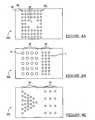
- Figure 4A-4C is a pore forming apparatus according to various embodiments of the present invention.
- Figure 5 is a flow chart for pore forming according to an embodiment.
- Figure 6 is a flow chart for pore forming according to an alternative embodiment.
- a laminated structure 10 includes at least two layers, a first layer 12 and a second layer 14 formed generally adjacent one another.
- an intermediate layer 16 may be formed or positioned between the first and second layers 12, 14.
- the intermediate layer 16 may be used for adhering the first and second layers 12, 14 to one another during a formation or laminating process.
- laminated layers may include a pre-impregnated material which can be used to affix the first and second layers 12, 14 together during the formation process.
- the first and second layers 12, 14 may be fixed to one another, during the formation process, without any additional adhesive material.
- the laminate structure 10 may include any number of appropriate layers.
- the laminate structure 10 including any appropriate number greater than the two structural layers 12, 14 and a single intermediate layer 16 may be used.
- the pores 20 can be formed through the laminate 10 in any appropriate or selected manner. Generally, however the pores 20 are formed such that a uniform density or porosity is formed in a selected area such as a first set of pores 22. Moreover, the pores may be formed such that a non-porous area 24 is also formed. Furthermore, the pores 20 may be formed to include desired physical characteristics such as being uni-directional. For example, uni-directional pores 26 allow the flow of a flowable material from a first side 12a to a second side 14a.
- a fourth exemplary formed pore includes an angled pore 27 which is formed at a selected angle ⁇ to a side of the laminate 10.
- the uni-directional pores 26 may also be formed such that material flows substantially only from the second side 14a to the first side 12a. In addition, due to the formation of the uni-directional pores 26, it may be that the uni-directional pores 26 are positioned in any selected area of the laminate 10.
- the first laminate layer 12 and the second laminate layer 14 may generally be formed of any appropriate material, for example non-oxide materials.
- the first layer may be formed substantially of a carbon reinforced silicon carbide material while the second layer 14 is formed substantially of a carbon reinforced carbon (Carbon-Carbon) material.
- both the first layer 12 and the second layer 14 may be formed of a carbon fiber reinforced silicon carbide material formed in an appropriate manner.
- the non-oxide first and second layers 12, 14 are formed to include selected physical characteristics, such as strength or durability.
- the first and second layers 12, 14 may be formed of a material that includes other physical characteristics such as thermal or electrical conductivity.
- the non-oxide materials may also be reinforced with carbon, silicon carbide, or other ceramic or metal fibers.
- the laminate structure 10 may include both selected physical properties and porosity.
- first layer 12 and a second layer 14 were individually porous providing the intermediate layer 16 may interrupt the continuous porosity from the first side 12a to the second side 14a.
- the porosity may not be substantially continuous or uniform over the entire surface of the laminate 10. Therefore, the porosity would be unknown at various areas of the laminate material 10.
- forming the pores 20 through the laminate 10 as the laminate 10 is formed substantially ensures that the porosity or the pores 20 formed in laminate 10 are formed in a selected manner and according to selected requirements. Moreover, forming the pores 20 during the manufacturing of the laminate 10 ensures that the formation of the pores 20 or the presence of the pores 20 does not destroy the selected physical or chemical characteristics of the laminate 10.
- the pores 20 may be formed using a pore forming apparatus 30.
- the pore forming apparatus 30 generally includes a base 32 and a plurality of pins or pore forming members 34 extending from the base 32.
- the pins 34 include a substantially sharpened top or engaging end 36 that is used to pierce a portion of a laminate preform 40.
- the laminate preform 40 includes each of the layers which will eventually form the laminate structure 10, but which have not yet been laminated (that is, the process to make each of the layers 12, 14 substantially coherent has not yet occurred).
- the layer 12, 14 of the laminate preform 40 may also include reinforcing fibers F, F'.
- the reinforcing fibers F, F' may be any appropriate material to provide selected properties to the layers 12, 14.
- the reinforcing fibers F' in the first layer 12 may be the same or different than the fibers F' in the second layer.
- the pins 34 pierce the laminate preform 40 to form desired pores in the laminate preform 40 which will become the pores 20 once the pins 34 are removed.
- the pins 34 are also able to move the fibers F, F' during the insertion of the pins 34. Therefore, the pins 34 do not destroy the fibers F, F' nor the properties they impart to the laminate 10, once formed.
- the laminate preform 40 is pressed onto the pins 34 to a selected depth or distance.
- the sharpened ends 36 and the pins 34 are able to move the fibers F, F' rather than break them.
- the fibers F, F' are able to move within the layers 12, 14 rather than breaking.
- the pins 34 include a height selected to provide a desired pore depth into the laminate structure 10.
- pores are formed through laminate structure 10 such that a flowable material is able to pass from the first side 12a to the second side 14a.
- the pore forming apparatus 30 can be pressed through the laminate preform 40 or the laminate preform 40 pressed onto the pore forming apparatus 30. Nevertheless, the pins 34 engage and typically pass through each of the layers of the laminate preform 40 to form regions that become the pores 20 in the laminate structure 10.
- the pins 34 may be formed or placed on the base 32 of the pore forming apparatus 30 in any appropriate shape or pattern. Moreover, the pin forming apparatus 30 may be shaped to any appropriate geometry. In this way as the laminate preform 40 is placed over the pore forming apparatus 30, it conforms to the shape of the pore forming apparatus 30 such that a complimentary shape or a similar shape is formed in the laminate preform 40 as the pores 20 are formed in the laminate preform 40.
- each of the pins 34 positioned on the base 32 may be of a selected size or geometry. Therefore, a first set of the pins 34 may be a first size, while a second set is a different size.
- the pins 34 may include a uni-directional pore shape, such that the flowable material passes only in one direction, and again only some of the pins placed on the base 32 may include this attribute while others do not.
- the pins 34 may pierce at some selected angle so as to create pores at the selected angle ⁇ .
- the pore forming apparatus 30a includes a plurality of the pins 34 formed in a plurality of rows 42 1 to 42 n .
- An opening 44 is left in the pattern such that pores will not be formed in a selected area of the laminate 10.
- the open area 44 may be any appropriate shape or size and may used for forming an opening or hole in the laminate 10. Particularly, if there is an opening for a rod or tube, no pores would be formed therein.
- the pore forming apparatus 30B includes a first set of pins 46 having a first diameter X and a second set of pins 48 having a second diameter Y.
- the first diameter X may be any diameter different than the diameter Y. Therefore, the laminate 10 will have pores formed therein that include pores of various sizes. This may be desirable especially if the laminate 10 is to be used to cover to adjacent sections requiring a different size pore in each section. This technique may also be used to vary the rate of material transport across different portions of the laminate 10.
- a pore forming apparatus 30c includes a first section of pins 50 and a second section of pins 52.
- the first section pins 50 may be formed in a particular pattern, such as a triangle for forming pores in the laminate 10 in the selected pattern.
- the pins in the first section 50 include a first density which is different than the density of the pins in the second section 52.
- the shape or general pattern of the second set of pins 52 may differ from the first set of pins 50. Therefore, several different pore forming apparatuses can be produced to provide various different porosities, pore sizes, pore shapes or pore patterns. In this way, the laminate 10 may include a porosity of any selected manner.
- a flow chart of a method 60 for forming the porosity in laminate 10 begins at step 62.
- a fabric stack or a fabric preform is formed in step 64. That is, that the first layer 12 and the second layer 14 of the laminate preform 40, before being laminated into a final laminate structure 10, are formed into the desired shape or size for being laminated.
- the first and second layers 12, 14 may be formed into a shape and size at the perform stage for which is required for the final laminate structure 10.
- the pin can be inserted in step 66.
- glass or molybdinum pins can be inserted at step 66 into the fabric preform. It will be understood that the pins may be inserted into the preform, formed in step 64, according to any selected size, porosity, or shape, as discussed above.
- the fabric preform may be tooled or worked at step 68. It will be understood that such tooling may not be desirable in the preform stage; therefore tooling is not necessary for carrying out the method 60. Nevertheless, certain tooling may be used to further modify the perform to achieve a desired shape or size.
- an interfacial coating is deposited upon the fiber preform utilizing chemical vapor deposition or polymer pyrolisis in step 70.
- the preform is infiltrated in step : 72 with a matrix material for example a silicon carbide ceramic via a polymer infiltration and pyrolysis (PIP), liquid metal melt infiltration (MI), or chemical vapor deposition (CVD) process.
- PIP polymer infiltration and pyrolysis
- MI liquid metal melt infiltration
- CVD chemical vapor deposition
- the preform is infiltrated with the material to allow lamination of each of the layers in the preform.
- a check for an appropriate density is done at step 74. If the material is not found to have a selected density, further infiltration is done of the preform in step 72.
- the pins may be etched out in step 76.
- the pins may be removed by destroying or abolishing the pins, such as by etching out in step 76 according to any appropriate manner. It will be understood the pins are generally destroyed during removal such that they are unusable yet the process leaves intact selected properties of the laminate.
- the pins may be generally etched out by chemical etching of the pins from the laminate structure 10. That is, that the glass or metal forming the pins that were placed in the preform are etched out with a chemical that does not react with the laminate materials, but only with the glass pins.
- the pins are inserted into the preform in step 64 and remain in place until after the laminate structure has been laminated or infiltrated in step 72.
- the pins inserted in step 66 are not removed from the preform structure until after the laminate structure is completely formed.
- the laminate is finished in step 78.
- the laminate finishing 78 may include any appropriate steps such as inspection, machining, and cleaning. Moreover, testing of the physical properties of the laminate may be done in the finishing step in step 78. If initial tooling was not done, or if initial tooling is done, final tooling of the laminate structure may be desirable in the finishing step 78 to provide for the selected structure shape or size.
- a second exemplary method to form the laminate 10 is illustrated according to a flow diagram 90.
- the second method 90 begins at start block 92.
- a stack fabric preform is formed in step 94.
- the fabric preform may be formed substantially similar to the fabric preform 64 according to the method 60.
- Polymer pins are inserted at step 96 into the fabric preform formed at step 94.
- the preform may be tooled at step 98.
- the pinned preform, tooled or untooled, is then infiltrated at step 102 for lamination of the layers.
- this process utilizes a polymer ceramic precursor which is solidified through a cure or drying process, which is pyrolized at step 102 to convert it into the desired ceramic.
- this may be the process to form silicon carbide around carbon fibers.
- the fabric preform is infiltrated with a selected polymer ceramic precursor or material at step 102.
- the infiltration allows for the laminate structure to form between the various layers of the stack fabric preform.
- the infiltration of the preform at step 102 substantially provides the density required for the laminate structure.
- the polymer pins may be melted out at step 104. More specifically, the laminated structure, including the polymer pins inserted therein, which were inserted into the preform at step 100, are destroyed or abolished. For example, the pins may be melted during the curing step. Generally the temperature required to melt out the polymer pins at step 104 is a temperature below that which substantially disrupts the structure of the laminate structure. Rather than injuring the structure of the laminate structure formed after the infiltration at step 102, the pins are simply melted out at step 104. This allows a substantially porous structure according to any selected design.
- the polymeric infiltrant is pyrolized according to the prescribed PIP process and converted into a ceramic in Step 102. It will be understood that PIP step 102 may occur at any appropriate time.
- the laminate is then finished in step 106. Similar to the laminate finish at step 78, various steps may be performed to finish the laminate at step 106. For example, the laminate structure may be examined for the desired physical and chemical properties, structure machined and cleaned. Furthermore, permeability testing of the laminate structure may occur to ensure that the selected permeability properties have been formed by the placement of the polymer pins into the preform in block 100.
- the materials for forming the laminate structure 10 are substantially non-oxide materials. Moreover, the materials forming the laminate structure 10 may be disrupted by oxidation of the materials in the various layers. Therefore, removing the pins, through any appropriate method, does not substantially oxidize the material of the laminate structure 10. To that end the pins may be selected of a material that may be removed using processes which do not substantially oxidizing the layers of the laminate 10.
- the materials forming the layers 12,14 of the laminate structure 10 allow for a substantially strong laminate.
- the placement of the pins 34 allow for the laminate structure 10 to be selectively porous. Therefore, a high strength laminate structure 10 or panel can be provided with a desired degree of porosity.
- the laminate preform 40 includes a plurality of independent layers of material placed adjacent one another. Then, as described above, a plurality of pores are formed in the laminate structure 10 by placing the pins 34 in the laminate preform 40.
- the plurality of pore forming members 34 are held in a selected plurality of independent layers of material until said laminated structure 10 is fully formed. Then the pins 34 are removed from the laminated substrate to form the pores 20.
- the pins may be formed from a polymer material of a selected diameter or density to penetrate the preform which can then be melt or burnt out during a pyrolysis cycle.
- a glass or metallic fiber may be used that can be etched out substantially easily following one or several infiltration cycles as determined by the particular infiltration method prescribed.
- pins 34 generally do not interact with the infiltration for formation of the laminate structure. More specifically, that the pins remain in place during the formation of the laminate but are easily removed afterwards to leave the desired porosity or pore size in the laminate structure 10. Therefore the pins do not generally interact with the infiltration material and generally only sublime or burn out when selected. Nevertheless, pins are provided that can be pressed through the preform laminate material without substantially deforming or substantially damaging reinforcements disposed in the laminate layers.
- the laminate structure 10 may be used for any appropriate use. Exemplary uses are described in U.S. Patent Application 10/ , (Attorney Docket 7784-000565) entitled, "A TRANSPIRATION COOLING SYSTEM” to Miklos Petervary, and commonly assigned, incorporated herein by reference.
- the laminate structure 10 including the pores 20 may be used for transpiration cooling of a structure.
- the laminate structure 10 may be used as the hot wall of a combustion chamber where a flowable cooling material that is flowed on the backside could then flow through the pores 20 at a selected rate to cool the hot wall surface.
- the present invention discloses a process for providing pores in a structure according to any selected physical characteristics.
- pins or pore forming members may be positioned in a laminate preform and the laminate preform formed into a laminate structure including the pins therein.
- the pins generally include a size, density, distribution, angle, or other characteristic that is desired in the final laminate structure. After the laminate is formed the pins are then removed from the laminate according to a process which does not harm a selected physical characteristics of the laminate structure.
Landscapes
- Chemical & Material Sciences (AREA)
- Engineering & Computer Science (AREA)
- Ceramic Engineering (AREA)
- Manufacturing & Machinery (AREA)
- Materials Engineering (AREA)
- Structural Engineering (AREA)
- Organic Chemistry (AREA)
- Life Sciences & Earth Sciences (AREA)
- Forests & Forestry (AREA)
- Mechanical Engineering (AREA)
- Chemical Kinetics & Catalysis (AREA)
- Laminated Bodies (AREA)
- Filtering Materials (AREA)
Abstract
Description
- The present invention relates generally to forming porous materials, and particularly to methods of forming selectively porous laminate materials.
- Many materials are known to be porous, generally being naturally porous. The naturally porous materials can be provided as filters or as transpiration coolers for various applications. Nevertheless, many natural materials include porosity that is also substantially "natural". Simply, the natural porosity of many materials is highly variable. Although porosity for various materials may be within a selected range, the porosity can be unevenly distributed throughout the material. Moreover, the natural porosity of a selected material may be within an extreme of a range rather than within a narrow porosity range.
- Nevertheless, it is desirable to provide materials that include a selected porosity. Generally these materials will include a porosity that is substantially consistent throughout the material such that natural variations do not occur within the material or are inconsequential relative to the selected porosity. Therefore, the porosity will include a selected porosity and pore size. The entire material will have known physical characteristics and can be applied in a substantially consistent manner.
- Moreover, most often porous materials include a substantially multi-directional porosity. That is, the porosity is distributed such that materials may move through the pores in multiple directions, from a first side to a second side and from the second side to the first side of the material as well as parallel to both sides. If the porous material is provided as a filter or membrane, then a pressure differential across the membrane must be relied upon to move the material in a selected direction. Generally, this requires including additional manufacturing steps or structural elements in the final structure or device.
- Therefore, it would be desirable to provide a material that is substantially directionally porous. More specifically, it would be desirable to provide a material having a porosity that allows material to flow along one direction relative to the porous material surfaces. The flow may be dependent upon the material in which the pores are made or the material being flowed across the membrane. Nevertheless, the membrane is substantially uni-directional in its porosity for selected flowable materials.
- It is also desired to provide many materials including selected porosities. That is, materials of various types including a selected porosity that includes a selected pore density, selected pore size, and selected directional porosity. Therefore, rather than providing only a single material including a selected porosity with a general technique, the materials could be varied and used in many different applications including different strengths and weight requirements.
- The invention provides a system for providing pores in a structure according to selected properties. Generally a structure, such as a laminate, may be formed with a selected pore according to a selected porosity or other physical attributes. The porosity may be formed by positioning pins or a pore forming member through a laminate preform before the preform is laminated to form the laminate structure. After forming the laminate structure the pins can be removed according to various processes which do not harm the physical characteristics of the laminate structure. Therefore, the porosity of the final laminate material is provided according to a selected size, direction, and porosity rather than being generally random according to a natural process.
- According to a first embodiment of the invention a method of forming a pore in a laminated material is disclosed. The method includes forming a laminate preform including a plurality of layers of material. A member is disposed at least partially through the laminate preform. The laminate preform may be processed to form a substantially laminated structure. The member is removed from the laminated structure. Removing the member is accomplished with substantially little oxidation and leaves a pore having at least one of desired shape and size.
- According to a second embodiment of the present invention a method for forming a laminate material including a selected pore is disclosed. The method includes selecting a substantially oxide-free fabric and forming a fabric stack including at least one layer of the selected substantially oxide-free fabric to be laminated into a substantially coherent laminate structure. A pin is placed into the fabric stack and then the fabric stack is laminated such that the fabric stack becomes laminated into a laminated structure. The pin is then removed from the laminated structure to form a substantially selected pore in the laminated structure.
- According to a third embodiment of the present invention a high strength panel providing a desired degree of porosity is disclosed. The high strength panel includes a laminated substrate including a plurality of independent layers of material placed adjacent one another. The panel further includes a plurality of pores formed in the laminated substrate by the placement of a plurality of pore forming members in at least a selected one of the plurality of independent layers of material prior to forming the laminated substrate. The plurality of pore forming members are held in the selected plurality of independent layers of material until the laminated substrate is fully formed and then removed from the laminated substrate to form the pores.
- Further areas of applicability of the present invention will become apparent from the detailed description provided hereinafter. It should be understood that the detailed description and various examples are intended for purposes of illustration only and are not intended to limit the scope of the invention.
- The present invention will become more fully understood from the detailed description and the accompanying drawings, wherein:
- Figure 1 is a cross-sectional view of a laminate including pores according to an embodiment of the present invention;
- Figure 2 is an exploded view of the laminate and a pore forming apparatus;
- Figure 3 is an assembled view of a laminate and a pore forming apparatus;
- Figure 4A-4C is a pore forming apparatus according to various embodiments of the present invention;
- Figure 5 is a flow chart for pore forming according to an embodiment; and
- Figure 6 is a flow chart for pore forming according to an alternative embodiment.
- The following description of various embodiments is merely exemplary in nature and is in no way intended to limit the invention, its application, or uses.
- With reference to Figure 1, a laminated
structure 10 includes at least two layers, afirst layer 12 and asecond layer 14 formed generally adjacent one another. In addition, anintermediate layer 16 may be formed or positioned between the first andsecond layers intermediate layer 16 may be used for adhering the first andsecond layers second layers second layers laminate structure 10 may include any number of appropriate layers. Simply, thefirst layer 12 affixed to thesecond layer 14 is shown for clarity and is merely exemplary and not intended to limit the scope of the present disclosure. Therefore, thelaminate structure 10 including any appropriate number greater than the twostructural layers intermediate layer 16 may be used. - Formed through the
laminate 10 is a plurality of bores orpores 20. Thepores 20 can be formed through the laminate 10 in any appropriate or selected manner. Generally, however thepores 20 are formed such that a uniform density or porosity is formed in a selected area such as a first set of pores 22. Moreover, the pores may be formed such that anon-porous area 24 is also formed. Furthermore, thepores 20 may be formed to include desired physical characteristics such as being uni-directional. For example,uni-directional pores 26 allow the flow of a flowable material from afirst side 12a to asecond side 14a. A fourth exemplary formed pore includes anangled pore 27 which is formed at a selected angle to a side of the laminate 10. This allows the material to flow to a selected area relative to thelaminate 10. It will be understood that theuni-directional pores 26 may also be formed such that material flows substantially only from thesecond side 14a to thefirst side 12a. In addition, due to the formation of theuni-directional pores 26, it may be that theuni-directional pores 26 are positioned in any selected area of the laminate 10. - The
first laminate layer 12 and thesecond laminate layer 14 may generally be formed of any appropriate material, for example non-oxide materials. For example, the first layer may be formed substantially of a carbon reinforced silicon carbide material while thesecond layer 14 is formed substantially of a carbon reinforced carbon (Carbon-Carbon) material. Alternatively, both thefirst layer 12 and thesecond layer 14 may be formed of a carbon fiber reinforced silicon carbide material formed in an appropriate manner. Generally, the non-oxide first andsecond layers second layers second layers laminate 10. Moreover, thepores 20 formed in the laminate 10 are formed without destroying the selected physical characteristics of the laminate 10. Thus thelaminate structure 10 may include both selected physical properties and porosity. - If the
first layer 12 and asecond layer 14 were individually porous providing theintermediate layer 16 may interrupt the continuous porosity from thefirst side 12a to thesecond side 14a. In addition, if thefirst layer 12 and thesecond layer 14 were inherently porous, the porosity may not be substantially continuous or uniform over the entire surface of the laminate 10. Therefore, the porosity would be unknown at various areas of thelaminate material 10. - Therefore, forming the
pores 20 through the laminate 10 as the laminate 10 is formed substantially ensures that the porosity or thepores 20 formed inlaminate 10 are formed in a selected manner and according to selected requirements. Moreover, forming thepores 20 during the manufacturing of the laminate 10 ensures that the formation of thepores 20 or the presence of thepores 20 does not destroy the selected physical or chemical characteristics of the laminate 10. - With reference to Figure 2, the pores 20 (illustrated in Figure 1) may be formed using a
pore forming apparatus 30. Thepore forming apparatus 30 generally includes abase 32 and a plurality of pins orpore forming members 34 extending from thebase 32. Generally, thepins 34 include a substantially sharpened top or engagingend 36 that is used to pierce a portion of alaminate preform 40. Thelaminate preform 40 includes each of the layers which will eventually form thelaminate structure 10, but which have not yet been laminated (that is, the process to make each of thelayers layer laminate preform 40 may also include reinforcing fibers F, F'. The reinforcing fibers F, F' may be any appropriate material to provide selected properties to thelayers first layer 12 may be the same or different than the fibers F' in the second layer. Thepins 34 pierce thelaminate preform 40 to form desired pores in thelaminate preform 40 which will become thepores 20 once thepins 34 are removed. - The
pins 34 are also able to move the fibers F, F' during the insertion of thepins 34. Therefore, thepins 34 do not destroy the fibers F, F' nor the properties they impart to the laminate 10, once formed. - With continued reference to Figure 2 and additional reference to Figure 3, the
laminate preform 40 is pressed onto thepins 34 to a selected depth or distance. During this process, the sharpened ends 36 and thepins 34 are able to move the fibers F, F' rather than break them. In the unprocessed state, the fibers F, F' are able to move within thelayers pins 34 include a height selected to provide a desired pore depth into thelaminate structure 10. Generally, pores are formed throughlaminate structure 10 such that a flowable material is able to pass from thefirst side 12a to thesecond side 14a. Thepore forming apparatus 30 can be pressed through thelaminate preform 40 or thelaminate preform 40 pressed onto thepore forming apparatus 30. Nevertheless, thepins 34 engage and typically pass through each of the layers of thelaminate preform 40 to form regions that become thepores 20 in thelaminate structure 10. - The
pins 34 may be formed or placed on thebase 32 of thepore forming apparatus 30 in any appropriate shape or pattern. Moreover, thepin forming apparatus 30 may be shaped to any appropriate geometry. In this way as thelaminate preform 40 is placed over thepore forming apparatus 30, it conforms to the shape of thepore forming apparatus 30 such that a complimentary shape or a similar shape is formed in thelaminate preform 40 as thepores 20 are formed in thelaminate preform 40. - Because the
pins 34 may be positioned on the base 32 in any appropriate configuration or pattern, selected porosities or designs of porosities can be formed in thelaminate 10. In addition, each of thepins 34 positioned on thebase 32 may be of a selected size or geometry. Therefore, a first set of thepins 34 may be a first size, while a second set is a different size. Moreover, thepins 34 may include a uni-directional pore shape, such that the flowable material passes only in one direction, and again only some of the pins placed on thebase 32 may include this attribute while others do not. Moreover, thepins 34 may pierce at some selected angle so as to create pores at the selected angle . - With reference to Figure 4A to 4C, exemplary pore forming geometries are illustrated. With particular reference to Figure 4A, the
pore forming apparatus 30a includes a plurality of thepins 34 formed in a plurality of rows 421 to 42n. Anopening 44 is left in the pattern such that pores will not be formed in a selected area of the laminate 10. Theopen area 44 may be any appropriate shape or size and may used for forming an opening or hole in thelaminate 10. Particularly, if there is an opening for a rod or tube, no pores would be formed therein. - With particular reference to Figure 4B, the pore forming apparatus 30B includes a first set of
pins 46 having a first diameter X and a second set ofpins 48 having a second diameter Y. The first diameter X may be any diameter different than the diameter Y. Therefore, the laminate 10 will have pores formed therein that include pores of various sizes. This may be desirable especially if the laminate 10 is to be used to cover to adjacent sections requiring a different size pore in each section. This technique may also be used to vary the rate of material transport across different portions of the laminate 10. - With particular reference to Figure 4C, a pore forming apparatus 30c includes a first section of
pins 50 and a second section of pins 52. The first section pins 50 may be formed in a particular pattern, such as a triangle for forming pores in the laminate 10 in the selected pattern. Moreover, the pins in thefirst section 50 include a first density which is different than the density of the pins in thesecond section 52. Furthermore, the shape or general pattern of the second set ofpins 52 may differ from the first set ofpins 50. Therefore, several different pore forming apparatuses can be produced to provide various different porosities, pore sizes, pore shapes or pore patterns. In this way, the laminate 10 may include a porosity of any selected manner. - With reference to Figure 5, a flow chart of a
method 60 for forming the porosity inlaminate 10 is illustrated. Themethod 60 begins at step 62. After the process has started, a fabric stack or a fabric preform is formed instep 64. That is, that thefirst layer 12 and thesecond layer 14 of thelaminate preform 40, before being laminated into afinal laminate structure 10, are formed into the desired shape or size for being laminated. The first andsecond layers final laminate structure 10. - After the stack fabric perform is formed in
step 64, the pin can be inserted instep 66. For example, glass or molybdinum pins can be inserted atstep 66 into the fabric preform. It will be understood that the pins may be inserted into the preform, formed instep 64, according to any selected size, porosity, or shape, as discussed above. - After the pins are inserted into the fabric preform at
step 66, the fabric preform may be tooled or worked atstep 68. It will be understood that such tooling may not be desirable in the preform stage; therefore tooling is not necessary for carrying out themethod 60. Nevertheless, certain tooling may be used to further modify the perform to achieve a desired shape or size. After the selected tooling is used or directly after the glass pins are inserted instep 66, an interfacial coating is deposited upon the fiber preform utilizing chemical vapor deposition or polymer pyrolisis instep 70. - After the pins have been inserted in
step 66 and the interfacial coating is applied instep 70, the preform is infiltrated in step : 72 with a matrix material for example a silicon carbide ceramic via a polymer infiltration and pyrolysis (PIP), liquid metal melt infiltration (MI), or chemical vapor deposition (CVD) process. The preform is infiltrated with the material to allow lamination of each of the layers in the preform. After the preform is infiltrated, a check for an appropriate density is done atstep 74. If the material is not found to have a selected density, further infiltration is done of the preform instep 72. - Once the selected density is reached of the infiltrated preform, the pins may be etched out in step 76. The pins may be removed by destroying or abolishing the pins, such as by etching out in step 76 according to any appropriate manner. It will be understood the pins are generally destroyed during removal such that they are unusable yet the process leaves intact selected properties of the laminate. For example, the pins may be generally etched out by chemical etching of the pins from the
laminate structure 10. That is, that the glass or metal forming the pins that were placed in the preform are etched out with a chemical that does not react with the laminate materials, but only with the glass pins. Therefore, it will be understood, that the pins are inserted into the preform instep 64 and remain in place until after the laminate structure has been laminated or infiltrated instep 72. Thus, the pins inserted instep 66 are not removed from the preform structure until after the laminate structure is completely formed. - After the glass pins are etched out in step 76, the laminate is finished in
step 78. The laminate finishing 78 may include any appropriate steps such as inspection, machining, and cleaning. Moreover, testing of the physical properties of the laminate may be done in the finishing step instep 78. If initial tooling was not done, or if initial tooling is done, final tooling of the laminate structure may be desirable in the finishingstep 78 to provide for the selected structure shape or size. - With reference to Figure 6, a second exemplary method to form the laminate 10 is illustrated according to a flow diagram 90. The
second method 90 begins atstart block 92. After thestart block 92, a stack fabric preform is formed instep 94. The fabric preform may be formed substantially similar to thefabric preform 64 according to themethod 60. Polymer pins are inserted atstep 96 into the fabric preform formed atstep 94. After the stack fabric preform is pinned atstep 96, the preform may be tooled at step 98. The pinned preform, tooled or untooled, is then infiltrated atstep 102 for lamination of the layers. Alternatively, for a ceramic laminated material, this process utilizes a polymer ceramic precursor which is solidified through a cure or drying process, which is pyrolized atstep 102 to convert it into the desired ceramic. In one example, this may be the process to form silicon carbide around carbon fibers. - After the polymer pins are inserted into the fabric preform, the fabric preform is infiltrated with a selected polymer ceramic precursor or material at
step 102. The infiltration allows for the laminate structure to form between the various layers of the stack fabric preform. The infiltration of the preform atstep 102 substantially provides the density required for the laminate structure. Although a checking process or step may follow the infiltration of the preform afterstep 102, the infiltration process is not generally repeated according to themethod 90. - After the fabric preform has been infiltrated at
step 102 and rigidized (i.e. cured), the polymer pins may be melted out atstep 104. More specifically, the laminated structure, including the polymer pins inserted therein, which were inserted into the preform atstep 100, are destroyed or abolished. For example, the pins may be melted during the curing step. Generally the temperature required to melt out the polymer pins atstep 104 is a temperature below that which substantially disrupts the structure of the laminate structure. Rather than injuring the structure of the laminate structure formed after the infiltration atstep 102, the pins are simply melted out atstep 104. This allows a substantially porous structure according to any selected design. - After the polymer pins are melted out of the laminate structure the polymeric infiltrant is pyrolized according to the prescribed PIP process and converted into a ceramic in
Step 102. It will be understood thatPIP step 102 may occur at any appropriate time. The laminate is then finished instep 106. Similar to the laminate finish atstep 78, various steps may be performed to finish the laminate atstep 106. For example, the laminate structure may be examined for the desired physical and chemical properties, structure machined and cleaned. Furthermore, permeability testing of the laminate structure may occur to ensure that the selected permeability properties have been formed by the placement of the polymer pins into the preform inblock 100. - Generally, the materials for forming the
laminate structure 10 are substantially non-oxide materials. Moreover, the materials forming thelaminate structure 10 may be disrupted by oxidation of the materials in the various layers. Therefore, removing the pins, through any appropriate method, does not substantially oxidize the material of thelaminate structure 10. To that end the pins may be selected of a material that may be removed using processes which do not substantially oxidizing the layers of the laminate 10. - Moreover, the materials forming the
layers laminate structure 10 allow for a substantially strong laminate. The placement of thepins 34 allow for thelaminate structure 10 to be selectively porous. Therefore, a highstrength laminate structure 10 or panel can be provided with a desired degree of porosity. Thelaminate preform 40 includes a plurality of independent layers of material placed adjacent one another. Then, as described above, a plurality of pores are formed in thelaminate structure 10 by placing thepins 34 in thelaminate preform 40. The plurality ofpore forming members 34 are held in a selected plurality of independent layers of material until saidlaminated structure 10 is fully formed. Then thepins 34 are removed from the laminated substrate to form thepores 20. - For example, the pins may be formed from a polymer material of a selected diameter or density to penetrate the preform which can then be melt or burnt out during a pyrolysis cycle. Alternatively, a glass or metallic fiber may be used that can be etched out substantially easily following one or several infiltration cycles as determined by the particular infiltration method prescribed. Although it will be understood that these are merely exemplary in nature and any appropriate materials for forming the
pins 34 for thepore forming structure 30 may be used. - In addition, the materials for forming
pins 34 generally do not interact with the infiltration for formation of the laminate structure. More specifically, that the pins remain in place during the formation of the laminate but are easily removed afterwards to leave the desired porosity or pore size in thelaminate structure 10. Therefore the pins do not generally interact with the infiltration material and generally only sublime or burn out when selected. Nevertheless, pins are provided that can be pressed through the preform laminate material without substantially deforming or substantially damaging reinforcements disposed in the laminate layers. - The
laminate structure 10 may be used for any appropriate use. Exemplary uses are described inU.S. Patent Application 10/ , (Attorney Docket 7784-000565) entitled, "A TRANSPIRATION COOLING SYSTEM" to Miklos Petervary, and commonly assigned, incorporated herein by reference. For example thelaminate structure 10 including thepores 20 may be used for transpiration cooling of a structure. In a further example, thelaminate structure 10 may be used as the hot wall of a combustion chamber where a flowable cooling material that is flowed on the backside could then flow through thepores 20 at a selected rate to cool the hot wall surface. Thelaminate structure 10, however, includes the selected porosity so that the selected flow rate occurs. Moreover, the substantially consistent porosity assures that the porosity is present in thelaminate structure 10 at the selected area thus providing uniform transpiration and therefore uniform cooling. - The description of the invention is merely exemplary in nature and, thus, variations that do not depart from the basic premise of the invention are intended to be within the scope of the invention. Such variations are not to be regarded as a departure from the scope of the invention.
- In summary, the present invention discloses a process for providing pores in a structure according to any selected physical characteristics. Generally pins or pore forming members may be positioned in a laminate preform and the laminate preform formed into a laminate structure including the pins therein. The pins generally include a size, density, distribution, angle, or other characteristic that is desired in the final laminate structure. After the laminate is formed the pins are then removed from the laminate according to a process which does not harm a selected physical characteristics of the laminate structure.
Claims (18)
- A method of forming a pore (20) in a laminated material, comprising:wherein destroying the member (30; 34) is accomplished with at least one of substantially little oxidation and degradation to the laminated materials.forming a laminate preform (40) including a plurality of layers (12, 14, 16) of material;disposing a member (30; 34) at least partially through said laminate preform (40);processing said laminate preform (40) to form a substantially laminated structure (10); anddestroying the member (30; 34) in the laminated structure (10);
- The method of claim 1, wherein forming a laminate preform (40) includes;
selecting the plurality of layers (12, 14, 16) of material to include a substantially 5 non-oxide material; and
selecting a physical property of the material. - The method of claim 1 or 2, wherein disposing the member (30; 34) through said laminate preform includes:positioning the member (30; 34) through said layers (12, 14, 16) of material in a selected manner.
- The method of one of claims 1 to 3, wherein disposing the member (30; 34) through said laminate preform (40) includes:selecting a member (30; 34) having a desired profile such that a pore (20) left in said laminated structure (10) by said member (30; 34) creates a substantially uni-directional flow of a flowable material.
- The method of one of claims 1 to 3, wherein disposing the member (30; 34) through said 20 laminate preform (40) includes:selecting a plurality of members (34; 46, 48, 50, 52) to provide a selected porosity in said laminated structure (10) when the plurality of members (34; 46-52) are removed from said laminate structure (10).
- The method of one of claims 1 to 5, wherein laminating said laminate preform (40) includes:infiltrating (72; 100) said laminate preform (40) with a laminating material to substantially laminate the laminate preform (40).
- The method of one of claims 1 to 6, wherein destroying the member (30; 34) in the laminated structure (10) includes:removing the member (30; 34) by at least one of etching, sublimation, and melting.
- The method of one of claims 1 to 7, further comprising:forming a plurality of pores (20) in said laminated structure (10); anddisposing said porous laminated structure (10) operably adjacent a structure to transpirationally cool said structure (10).
- The method of one of claims 1 to 8, further comprising:wherein a coolant is able to flow through said pores (20) to cool said hot wall.forming a plurality of pores (20) in said laminated structure (10); andforming a hot wall of said laminated structure (10);
- The method of one of claims 1 to 9, further comprising:forming a pore (20) having at least one of a selected size, shape, dimension, and property.
- A method for forming a laminate material including a selected pore (20), comprising:selecting a substantially oxide-free fabric;forming (94) a fabric stack including at least one layer (12-16) of said selected substantially oxide-free fabric to be laminated into a substantially coherent laminate structure (10);placing (96) a pin (34) into the fabric stack;laminating the fabric stack such that the fabric stack becomes laminated into a laminated structure (10); andremoving the pin (34) from the laminated structure (10) to form a substantially selected pore (20) in the laminated structure (10).
- The method of claim 11, wherein selecting the substantially oxide-free fabric includes;
selecting a material from the group including: carbon fiber, silicon carbide fiber, polymeric fibrous materials, and combinations thereof. - The method material of claim 11 or 12, wherein forming the fabric stack includes:wherein said first layer (12) and said second layer (14) are positioned in a selected orientation for forming the laminated structure (10).disposing at least a first substantially oxide-free fabric layer (12) substantially adjacent a second substantially oxide-free fabric layer (14); and
- The method of claim 13, wherein placing the pin (34) into the fabric stack includes:moving the pin (34) through each of the layers (12, 14, 16) of the fabric stack without substantially disrupting the selected orientation of each of said layers (12, 14, 16).
- The method of one of claims 11 to 14, wherein placing the pin (34) into the fabric stack includes:moving the pin (34) through fabric stack such that the pin (34) is disposed through selected layers (12, 14, 16) of said fabric stack.
- The method of one of claims 11 to 19, wherein placing the pin (34) into the fabric stack includes:placing the pin (34) at a selected angle such that said selected pore (20) remaining in said laminated structure (10) allows for substantially uni-directional flow of a flowable material through the laminated structure (10) of said selected angle.
- The method of claim 6, wherein said laminating material is substantially non-reactive with said plurality of pore forming members (30).
- A high strength panel providing a desired degree of porosity, comprising:wherein said plurality of pore forming members (30; 34) are held in said selected plurality of independent layers (12, 14, 16) of material until said laminated substrate (10) is fully formed and then destroyed in said laminated substrate (10) to form said pores (20).a laminated substrate (10) including a plurality of independent layers (12, 14, 16) of material placed adjacent one another;a plurality of pores (20) formed in said laminated substrate (10) by the placement of a plurality of pore forming members (30; 34) in at least a selected one of said plurality of independent layers (12, 14, 16) of material prior to forming said laminated substrate; and
Priority Applications (2)
| Application Number | Priority Date | Filing Date | Title |
|---|---|---|---|
| EP14163819.7A EP2762311B1 (en) | 2003-07-22 | 2004-07-14 | Manufacturing method of a forming structure including a selected porosity |
| EP18150166.9A EP3326814B1 (en) | 2003-07-22 | 2004-07-14 | High strength laminate structure |
Applications Claiming Priority (2)
| Application Number | Priority Date | Filing Date | Title |
|---|---|---|---|
| US10/624,905 US7332116B2 (en) | 2003-07-22 | 2003-07-22 | Method for forming non-oxide selectively porous materials |
| US624905 | 2003-07-22 |
Related Child Applications (3)
| Application Number | Title | Priority Date | Filing Date |
|---|---|---|---|
| EP14163819.7A Division EP2762311B1 (en) | 2003-07-22 | 2004-07-14 | Manufacturing method of a forming structure including a selected porosity |
| EP14163819.7A Division-Into EP2762311B1 (en) | 2003-07-22 | 2004-07-14 | Manufacturing method of a forming structure including a selected porosity |
| EP18150166.9A Division EP3326814B1 (en) | 2003-07-22 | 2004-07-14 | High strength laminate structure |
Publications (3)
| Publication Number | Publication Date |
|---|---|
| EP1500497A2 true EP1500497A2 (en) | 2005-01-26 |
| EP1500497A3 EP1500497A3 (en) | 2009-12-30 |
| EP1500497B1 EP1500497B1 (en) | 2014-06-11 |
Family
ID=33490874
Family Applications (3)
| Application Number | Title | Priority Date | Filing Date |
|---|---|---|---|
| EP20040016510 Expired - Lifetime EP1500497B1 (en) | 2003-07-22 | 2004-07-14 | Method for forming a laminate material with a predetermined porosity |
| EP18150166.9A Expired - Lifetime EP3326814B1 (en) | 2003-07-22 | 2004-07-14 | High strength laminate structure |
| EP14163819.7A Expired - Lifetime EP2762311B1 (en) | 2003-07-22 | 2004-07-14 | Manufacturing method of a forming structure including a selected porosity |
Family Applications After (2)
| Application Number | Title | Priority Date | Filing Date |
|---|---|---|---|
| EP18150166.9A Expired - Lifetime EP3326814B1 (en) | 2003-07-22 | 2004-07-14 | High strength laminate structure |
| EP14163819.7A Expired - Lifetime EP2762311B1 (en) | 2003-07-22 | 2004-07-14 | Manufacturing method of a forming structure including a selected porosity |
Country Status (4)
| Country | Link |
|---|---|
| US (2) | US7332116B2 (en) |
| EP (3) | EP1500497B1 (en) |
| JP (1) | JP2005041218A (en) |
| AU (1) | AU2004202893B2 (en) |
Cited By (2)
| Publication number | Priority date | Publication date | Assignee | Title |
|---|---|---|---|---|
| CN102962863A (en) * | 2012-12-19 | 2013-03-13 | 滁州金鼎机电装备制造有限公司 | High-pressure foaming ventilation hole punching device for refrigerator liner |
| FR3166325A1 (en) * | 2024-09-19 | 2026-03-20 | Safran Nacelles | METHOD FOR MANUFACTURING AN ACOUSTIC SKIN MADE OF CERAMIC MATRIX COMPOSITE MATERIAL AND ROBOTIC SYSTEM FOR IMPLEMENTING SUCH A METHOD |
Families Citing this family (17)
| Publication number | Priority date | Publication date | Assignee | Title |
|---|---|---|---|---|
| EP1602623B1 (en) * | 2003-03-07 | 2011-08-17 | Tosoh Corporation | Method of moulding a microfluidic structure and mould |
| FR2926745B1 (en) * | 2008-01-28 | 2013-04-12 | Hacoma | METHOD AND DEVICE FOR PERFORMING DRILLING IN THERMOPLASTIC COMPOSITE MATERIAL |
| ITCT20080001U1 (en) * | 2008-03-07 | 2009-09-08 | Meli Giuseppe | IMPROVED DEVICE FOR THE PRODUCTION OF COMPOSITE STRUCTURES WITH A FLOOR SECTION WITH CHIRAL OR AUXETIC ASSIMETRIC GEOMETRY BUT USABLE FOR THE PRODUCTION OF GRILLES OF ANY SHAPE. |
| US8357323B2 (en) * | 2008-07-16 | 2013-01-22 | Siemens Energy, Inc. | Ceramic matrix composite wall with post laminate stitching |
| TWM351533U (en) * | 2008-07-29 | 2009-02-21 | Hon Hai Prec Ind Co Ltd | Electrical connector assembly |
| WO2010057089A1 (en) * | 2008-11-17 | 2010-05-20 | Textron Systems Corporation | Techniques for forming temporary protective coatings and bondable surfaces |
| US20150185872A1 (en) * | 2014-01-02 | 2015-07-02 | Gerald Leto | Glove for use with capacitive touch screen and method of manufacturing same |
| US20160135563A1 (en) * | 2014-11-14 | 2016-05-19 | Traveler's Choice | Luggage handle system |
| US10024175B2 (en) | 2015-05-26 | 2018-07-17 | Rolls-Royce Corporation | Cooling holes manufactured with EBC in place |
| US9797263B2 (en) | 2015-05-26 | 2017-10-24 | Rolls-Royce Corporation | Monolithic ceramic rods to enable cooling holes in CMC |
| US10207471B2 (en) * | 2016-05-04 | 2019-02-19 | General Electric Company | Perforated ceramic matrix composite ply, ceramic matrix composite article, and method for forming ceramic matrix composite article |
| US11021779B2 (en) * | 2017-05-01 | 2021-06-01 | Rolls-Royce High Temperature Composites Inc. | Sacrificial 3-dimensional weaving method and ceramic matrix composites formed therefrom |
| US10439713B1 (en) * | 2018-03-15 | 2019-10-08 | The Boeing Company | System and method for receiving signal information for networking using a free space optical link |
| CN112765913B (en) * | 2021-04-08 | 2021-06-29 | 中国空气动力研究与发展中心计算空气动力研究所 | Layered gradient porous material sweating cooling structure and aircraft |
| DE102021120637A1 (en) * | 2021-08-09 | 2023-02-09 | Arianegroup Gmbh | Rocket engine section with porous inner wall part and method of making a rocket engine section |
| US12552085B2 (en) | 2023-10-20 | 2026-02-17 | Rtx Corporation | Z-channeling into a preform via needle perforation in a stand-alone tool |
| US12473236B2 (en) * | 2023-10-20 | 2025-11-18 | Rtx Corporation | Internal tooling configuration for the creation of z-channels in woven ceramic matrix composite preforms |
Family Cites Families (21)
| Publication number | Priority date | Publication date | Assignee | Title |
|---|---|---|---|---|
| US3940532A (en) * | 1972-01-28 | 1976-02-24 | The Fiberwoven Corporation | Needled textile fabric with a thin polymeric coating thereon |
| US3864199A (en) | 1973-07-26 | 1975-02-04 | Gen Motors Corp | Angular discharge porous sheet |
| US3865199A (en) * | 1974-03-25 | 1975-02-11 | Schlumberger Technology Corp | Apparatus for perforating sub-sea well bores |
| JPS60180800A (en) * | 1984-02-27 | 1985-09-14 | 富士重工業株式会社 | Method and device for boring and machining composite resin molded shape |
| US4562039A (en) | 1984-06-27 | 1985-12-31 | Pall Corporation | Porous metal article and method of making |
| GB8620483D0 (en) | 1986-08-22 | 1986-10-01 | Raychem Ltd | Laminated article |
| US5252279A (en) | 1991-01-17 | 1993-10-12 | Reinhold Industries | Method for making perforated articles |
| US5246520A (en) * | 1991-02-12 | 1993-09-21 | Auto-Air Composites, Inc. | One step molded continuous fiber reinforced perforated composite panels |
| TW266186B (en) * | 1992-05-01 | 1995-12-21 | Martin Marietta Corp | |
| US5334414A (en) * | 1993-01-22 | 1994-08-02 | Clemson University | Process for coating carbon fibers with pitch and composites made therefrom |
| US5577381A (en) * | 1994-12-06 | 1996-11-26 | United Technologies Corporation | Exhaust nozzle cooling scheme for gas turbine engine |
| JPH08236093A (en) * | 1995-02-27 | 1996-09-13 | Mitsubishi Chem Corp | Battery separator |
| US6418973B1 (en) | 1996-10-24 | 2002-07-16 | Boeing North American, Inc. | Integrally woven ceramic composites |
| GB2323056A (en) * | 1997-03-14 | 1998-09-16 | Gkn Westland Helicopters Ltd | Method of forming a composite panel provided with a plurality of holes |
| DE19730674A1 (en) * | 1997-07-17 | 1999-01-21 | Deutsch Zentr Luft & Raumfahrt | Combustion chamber and method of manufacturing a combustion chamber |
| US6190602B1 (en) | 1998-03-13 | 2001-02-20 | Aztex, Inc. | Method of manufacturing a perforated laminate |
| CN1305412A (en) * | 1998-06-15 | 2001-07-25 | 美国3M公司 | Multi-component unidirectional graphic article |
| US6758386B2 (en) | 2001-09-18 | 2004-07-06 | The Boeing Company | Method of joining ceramic matrix composites and metals |
| US7303597B2 (en) | 2002-10-15 | 2007-12-04 | Pratt & Whitney Rocketdyne, Inc. | Method and apparatus for continuously feeding and pressurizing a solid material into a high pressure system |
| FR2852003B1 (en) * | 2003-03-04 | 2005-05-27 | Snecma Propulsion Solide | PROCESS FOR PRODUCING A MULTIPERFORATED PART IN CERAMIC MATRIX COMPOSITE MATERIAL |
| US6920836B2 (en) | 2003-10-02 | 2005-07-26 | The Boeing Company | Regeneratively cooled synthesis gas generator |
-
2003
- 2003-07-22 US US10/624,905 patent/US7332116B2/en not_active Expired - Lifetime
-
2004
- 2004-06-28 AU AU2004202893A patent/AU2004202893B2/en not_active Expired
- 2004-07-12 JP JP2004204606A patent/JP2005041218A/en active Pending
- 2004-07-14 EP EP20040016510 patent/EP1500497B1/en not_active Expired - Lifetime
- 2004-07-14 EP EP18150166.9A patent/EP3326814B1/en not_active Expired - Lifetime
- 2004-07-14 EP EP14163819.7A patent/EP2762311B1/en not_active Expired - Lifetime
-
2008
- 2008-01-04 US US11/969,543 patent/US8057880B2/en not_active Expired - Lifetime
Non-Patent Citations (1)
| Title |
|---|
| None |
Cited By (2)
| Publication number | Priority date | Publication date | Assignee | Title |
|---|---|---|---|---|
| CN102962863A (en) * | 2012-12-19 | 2013-03-13 | 滁州金鼎机电装备制造有限公司 | High-pressure foaming ventilation hole punching device for refrigerator liner |
| FR3166325A1 (en) * | 2024-09-19 | 2026-03-20 | Safran Nacelles | METHOD FOR MANUFACTURING AN ACOUSTIC SKIN MADE OF CERAMIC MATRIX COMPOSITE MATERIAL AND ROBOTIC SYSTEM FOR IMPLEMENTING SUCH A METHOD |
Also Published As
| Publication number | Publication date |
|---|---|
| EP2762311A3 (en) | 2015-05-06 |
| US8057880B2 (en) | 2011-11-15 |
| EP3326814A1 (en) | 2018-05-30 |
| US20080102265A1 (en) | 2008-05-01 |
| EP1500497A3 (en) | 2009-12-30 |
| EP3326814B1 (en) | 2020-01-29 |
| JP2005041218A (en) | 2005-02-17 |
| EP1500497B1 (en) | 2014-06-11 |
| EP2762311A2 (en) | 2014-08-06 |
| US7332116B2 (en) | 2008-02-19 |
| AU2004202893A1 (en) | 2005-02-10 |
| EP2762311B1 (en) | 2018-04-11 |
| US20050017389A1 (en) | 2005-01-27 |
| AU2004202893B2 (en) | 2010-12-09 |
Similar Documents
| Publication | Publication Date | Title |
|---|---|---|
| US8057880B2 (en) | Non-oxide selectively porous materials | |
| EP2052853B1 (en) | A thermal protection system and a method for sealing a gap in this system | |
| EP4344843A1 (en) | Spiked preform tooling for improved chemical vapor infiltration in ceramic matrix composites | |
| EP3825296B1 (en) | Heat treatment method of slurry infiltrated fiber preform | |
| US20200308066A1 (en) | Ceramic Matrix Composite Articles and Methods for Manufacturing the Same | |
| EP4286127B1 (en) | A fibrous preform comprising a plurality of hourglass-shaped voids | |
| EP4375038B1 (en) | Methods for selective needling of fibrous preforms for shape-forming | |
| CN111315711A (en) | Method of manufacturing parts made of CMC | |
| EP4454842A1 (en) | Z-channel creation in woven preform by incorporation of pin features into preform tooling | |
| EP4431254A2 (en) | Sheathed metallic needles for producing z-channels in fibrous preforms | |
| EP4541535A1 (en) | Z-channeling into a preform via needle perforation in a stand-alone tool | |
| US6177146B1 (en) | Densification of a porous structure (III) | |
| KR101679581B1 (en) | Method for making carbon-carbon composite | |
| EP4197988A1 (en) | Freeze drying of composites for filament spreading | |
| JP2018009241A (en) | Systems and methods for forming metal matrix composites | |
| EP4628473A1 (en) | Cores for ceramic matrix composite components | |
| EP4470740A1 (en) | Additively manufactured graphite tooling | |
| EP4345188A1 (en) | Ceramic matrix composite tooling for chemical vapor infiltration process | |
| EP4628472A1 (en) | Cores for ceramic matrix composite components | |
| EP4431483A1 (en) | Three dimensional weave with sacrifical z-fibers for improved ceramic matrix composite microstructure | |
| EP4477413A1 (en) | Particle enhanced ceramic matrix composite with no particles on surface plies | |
| EP4470992A1 (en) | Prefabricated noodle | |
| RU2793311C2 (en) | Method for manufacturing a part from composite material with ceramic matrix | |
| JP2007070223A (en) | Method for manufacturing silicon infiltration molded body |
Legal Events
| Date | Code | Title | Description |
|---|---|---|---|
| PUAI | Public reference made under article 153(3) epc to a published international application that has entered the european phase |
Free format text: ORIGINAL CODE: 0009012 |
|
| AK | Designated contracting states |
Kind code of ref document: A2 Designated state(s): AT BE BG CH CY CZ DE DK EE ES FI FR GB GR HU IE IT LI LU MC NL PL PT RO SE SI SK TR |
|
| AX | Request for extension of the european patent |
Extension state: AL HR LT LV MK |
|
| PUAL | Search report despatched |
Free format text: ORIGINAL CODE: 0009013 |
|
| AK | Designated contracting states |
Kind code of ref document: A3 Designated state(s): AT BE BG CH CY CZ DE DK EE ES FI FR GB GR HU IE IT LI LU MC NL PL PT RO SE SI SK TR |
|
| AX | Request for extension of the european patent |
Extension state: AL HR LT LV MK |
|
| 17P | Request for examination filed |
Effective date: 20100609 |
|
| AKX | Designation fees paid |
Designated state(s): AT BE BG CH CY CZ DE DK EE ES FI FR GB GR HU IE IT LI LU MC NL PL PT RO SE SI SK TR |
|
| 17Q | First examination report despatched |
Effective date: 20101026 |
|
| REG | Reference to a national code |
Ref country code: DE Ref legal event code: R079 Ref document number: 602004045242 Country of ref document: DE Free format text: PREVIOUS MAIN CLASS: B32B0031160000 Ipc: B32B0018000000 |
|
| GRAP | Despatch of communication of intention to grant a patent |
Free format text: ORIGINAL CODE: EPIDOSNIGR1 |
|
| RIC1 | Information provided on ipc code assigned before grant |
Ipc: B26F 1/24 20060101ALI20131202BHEP Ipc: B32B 18/00 20060101AFI20131202BHEP Ipc: B32B 38/04 20060101ALI20131202BHEP Ipc: C04B 35/571 20060101ALI20131202BHEP Ipc: C04B 35/80 20060101ALI20131202BHEP |
|
| INTG | Intention to grant announced |
Effective date: 20131216 |
|
| GRAS | Grant fee paid |
Free format text: ORIGINAL CODE: EPIDOSNIGR3 |
|
| GRAA | (expected) grant |
Free format text: ORIGINAL CODE: 0009210 |
|
| AK | Designated contracting states |
Kind code of ref document: B1 Designated state(s): AT BE BG CH CY CZ DE DK EE ES FI FR GB GR HU IE IT LI LU MC NL PL PT RO SE SI SK TR |
|
| REG | Reference to a national code |
Ref country code: GB Ref legal event code: FG4D |
|
| REG | Reference to a national code |
Ref country code: CH Ref legal event code: EP |
|
| REG | Reference to a national code |
Ref country code: IE Ref legal event code: FG4D |
|
| REG | Reference to a national code |
Ref country code: AT Ref legal event code: REF Ref document number: 672042 Country of ref document: AT Kind code of ref document: T Effective date: 20140715 |
|
| REG | Reference to a national code |
Ref country code: DE Ref legal event code: R096 Ref document number: 602004045242 Country of ref document: DE Effective date: 20140724 |
|
| PG25 | Lapsed in a contracting state [announced via postgrant information from national office to epo] |
Ref country code: GR Free format text: LAPSE BECAUSE OF FAILURE TO SUBMIT A TRANSLATION OF THE DESCRIPTION OR TO PAY THE FEE WITHIN THE PRESCRIBED TIME-LIMIT Effective date: 20140912 Ref country code: FI Free format text: LAPSE BECAUSE OF FAILURE TO SUBMIT A TRANSLATION OF THE DESCRIPTION OR TO PAY THE FEE WITHIN THE PRESCRIBED TIME-LIMIT Effective date: 20140611 |
|
| REG | Reference to a national code |
Ref country code: NL Ref legal event code: VDEP Effective date: 20140611 |
|
| REG | Reference to a national code |
Ref country code: AT Ref legal event code: MK05 Ref document number: 672042 Country of ref document: AT Kind code of ref document: T Effective date: 20140611 |
|
| PG25 | Lapsed in a contracting state [announced via postgrant information from national office to epo] |
Ref country code: SE Free format text: LAPSE BECAUSE OF FAILURE TO SUBMIT A TRANSLATION OF THE DESCRIPTION OR TO PAY THE FEE WITHIN THE PRESCRIBED TIME-LIMIT Effective date: 20140611 |
|
| PG25 | Lapsed in a contracting state [announced via postgrant information from national office to epo] |
Ref country code: SK Free format text: LAPSE BECAUSE OF FAILURE TO SUBMIT A TRANSLATION OF THE DESCRIPTION OR TO PAY THE FEE WITHIN THE PRESCRIBED TIME-LIMIT Effective date: 20140611 Ref country code: ES Free format text: LAPSE BECAUSE OF FAILURE TO SUBMIT A TRANSLATION OF THE DESCRIPTION OR TO PAY THE FEE WITHIN THE PRESCRIBED TIME-LIMIT Effective date: 20140611 Ref country code: RO Free format text: LAPSE BECAUSE OF FAILURE TO SUBMIT A TRANSLATION OF THE DESCRIPTION OR TO PAY THE FEE WITHIN THE PRESCRIBED TIME-LIMIT Effective date: 20140611 Ref country code: PT Free format text: LAPSE BECAUSE OF FAILURE TO SUBMIT A TRANSLATION OF THE DESCRIPTION OR TO PAY THE FEE WITHIN THE PRESCRIBED TIME-LIMIT Effective date: 20141013 Ref country code: CZ Free format text: LAPSE BECAUSE OF FAILURE TO SUBMIT A TRANSLATION OF THE DESCRIPTION OR TO PAY THE FEE WITHIN THE PRESCRIBED TIME-LIMIT Effective date: 20140611 Ref country code: EE Free format text: LAPSE BECAUSE OF FAILURE TO SUBMIT A TRANSLATION OF THE DESCRIPTION OR TO PAY THE FEE WITHIN THE PRESCRIBED TIME-LIMIT Effective date: 20140611 |
|
| PG25 | Lapsed in a contracting state [announced via postgrant information from national office to epo] |
Ref country code: PL Free format text: LAPSE BECAUSE OF FAILURE TO SUBMIT A TRANSLATION OF THE DESCRIPTION OR TO PAY THE FEE WITHIN THE PRESCRIBED TIME-LIMIT Effective date: 20140611 Ref country code: AT Free format text: LAPSE BECAUSE OF FAILURE TO SUBMIT A TRANSLATION OF THE DESCRIPTION OR TO PAY THE FEE WITHIN THE PRESCRIBED TIME-LIMIT Effective date: 20140611 Ref country code: NL Free format text: LAPSE BECAUSE OF FAILURE TO SUBMIT A TRANSLATION OF THE DESCRIPTION OR TO PAY THE FEE WITHIN THE PRESCRIBED TIME-LIMIT Effective date: 20140611 |
|
| REG | Reference to a national code |
Ref country code: CH Ref legal event code: PL |
|
| REG | Reference to a national code |
Ref country code: DE Ref legal event code: R097 Ref document number: 602004045242 Country of ref document: DE |
|
| PG25 | Lapsed in a contracting state [announced via postgrant information from national office to epo] |
Ref country code: MC Free format text: LAPSE BECAUSE OF FAILURE TO SUBMIT A TRANSLATION OF THE DESCRIPTION OR TO PAY THE FEE WITHIN THE PRESCRIBED TIME-LIMIT Effective date: 20140611 |
|
| PLBE | No opposition filed within time limit |
Free format text: ORIGINAL CODE: 0009261 |
|
| STAA | Information on the status of an ep patent application or granted ep patent |
Free format text: STATUS: NO OPPOSITION FILED WITHIN TIME LIMIT |
|
| REG | Reference to a national code |
Ref country code: IE Ref legal event code: MM4A |
|
| PG25 | Lapsed in a contracting state [announced via postgrant information from national office to epo] |
Ref country code: LI Free format text: LAPSE BECAUSE OF NON-PAYMENT OF DUE FEES Effective date: 20140731 Ref country code: CH Free format text: LAPSE BECAUSE OF NON-PAYMENT OF DUE FEES Effective date: 20140731 Ref country code: DK Free format text: LAPSE BECAUSE OF FAILURE TO SUBMIT A TRANSLATION OF THE DESCRIPTION OR TO PAY THE FEE WITHIN THE PRESCRIBED TIME-LIMIT Effective date: 20140611 Ref country code: IT Free format text: LAPSE BECAUSE OF FAILURE TO SUBMIT A TRANSLATION OF THE DESCRIPTION OR TO PAY THE FEE WITHIN THE PRESCRIBED TIME-LIMIT Effective date: 20140611 |
|
| 26N | No opposition filed |
Effective date: 20150312 |
|
| REG | Reference to a national code |
Ref country code: DE Ref legal event code: R097 Ref document number: 602004045242 Country of ref document: DE Effective date: 20150312 |
|
| PG25 | Lapsed in a contracting state [announced via postgrant information from national office to epo] |
Ref country code: BE Free format text: LAPSE BECAUSE OF FAILURE TO SUBMIT A TRANSLATION OF THE DESCRIPTION OR TO PAY THE FEE WITHIN THE PRESCRIBED TIME-LIMIT Effective date: 20140611 |
|
| PG25 | Lapsed in a contracting state [announced via postgrant information from national office to epo] |
Ref country code: SI Free format text: LAPSE BECAUSE OF FAILURE TO SUBMIT A TRANSLATION OF THE DESCRIPTION OR TO PAY THE FEE WITHIN THE PRESCRIBED TIME-LIMIT Effective date: 20140611 |
|
| PG25 | Lapsed in a contracting state [announced via postgrant information from national office to epo] |
Ref country code: IE Free format text: LAPSE BECAUSE OF NON-PAYMENT OF DUE FEES Effective date: 20140714 |
|
| PG25 | Lapsed in a contracting state [announced via postgrant information from national office to epo] |
Ref country code: BG Free format text: LAPSE BECAUSE OF FAILURE TO SUBMIT A TRANSLATION OF THE DESCRIPTION OR TO PAY THE FEE WITHIN THE PRESCRIBED TIME-LIMIT Effective date: 20140611 |
|
| PG25 | Lapsed in a contracting state [announced via postgrant information from national office to epo] |
Ref country code: CY Free format text: LAPSE BECAUSE OF FAILURE TO SUBMIT A TRANSLATION OF THE DESCRIPTION OR TO PAY THE FEE WITHIN THE PRESCRIBED TIME-LIMIT Effective date: 20140611 |
|
| REG | Reference to a national code |
Ref country code: FR Ref legal event code: PLFP Year of fee payment: 13 |
|
| PG25 | Lapsed in a contracting state [announced via postgrant information from national office to epo] |
Ref country code: HU Free format text: LAPSE BECAUSE OF FAILURE TO SUBMIT A TRANSLATION OF THE DESCRIPTION OR TO PAY THE FEE WITHIN THE PRESCRIBED TIME-LIMIT; INVALID AB INITIO Effective date: 20040714 Ref country code: LU Free format text: LAPSE BECAUSE OF NON-PAYMENT OF DUE FEES Effective date: 20140714 Ref country code: TR Free format text: LAPSE BECAUSE OF FAILURE TO SUBMIT A TRANSLATION OF THE DESCRIPTION OR TO PAY THE FEE WITHIN THE PRESCRIBED TIME-LIMIT Effective date: 20140611 |
|
| REG | Reference to a national code |
Ref country code: FR Ref legal event code: PLFP Year of fee payment: 14 |
|
| REG | Reference to a national code |
Ref country code: FR Ref legal event code: PLFP Year of fee payment: 15 |
|
| P01 | Opt-out of the competence of the unified patent court (upc) registered |
Effective date: 20230503 |
|
| PGFP | Annual fee paid to national office [announced via postgrant information from national office to epo] |
Ref country code: GB Payment date: 20230727 Year of fee payment: 20 |
|
| PGFP | Annual fee paid to national office [announced via postgrant information from national office to epo] |
Ref country code: FR Payment date: 20230725 Year of fee payment: 20 Ref country code: DE Payment date: 20230727 Year of fee payment: 20 |
|
| REG | Reference to a national code |
Ref country code: DE Ref legal event code: R071 Ref document number: 602004045242 Country of ref document: DE |
|
| REG | Reference to a national code |
Ref country code: GB Ref legal event code: PE20 Expiry date: 20240713 |
|
| PG25 | Lapsed in a contracting state [announced via postgrant information from national office to epo] |
Ref country code: GB Free format text: LAPSE BECAUSE OF EXPIRATION OF PROTECTION Effective date: 20240713 |
|
| PG25 | Lapsed in a contracting state [announced via postgrant information from national office to epo] |
Ref country code: GB Free format text: LAPSE BECAUSE OF EXPIRATION OF PROTECTION Effective date: 20240713 |