EP1500380A2 - Méthode de fabrication d'un préforme prothétique destinée à être visée sur des implants dentaires - Google Patents
Méthode de fabrication d'un préforme prothétique destinée à être visée sur des implants dentaires Download PDFInfo
- Publication number
- EP1500380A2 EP1500380A2 EP04425318A EP04425318A EP1500380A2 EP 1500380 A2 EP1500380 A2 EP 1500380A2 EP 04425318 A EP04425318 A EP 04425318A EP 04425318 A EP04425318 A EP 04425318A EP 1500380 A2 EP1500380 A2 EP 1500380A2
- Authority
- EP
- European Patent Office
- Prior art keywords
- implants
- implant
- gauge
- head
- head portion
- Prior art date
- Legal status (The legal status is an assumption and is not a legal conclusion. Google has not performed a legal analysis and makes no representation as to the accuracy of the status listed.)
- Withdrawn
Links
Images
Classifications
-
- A—HUMAN NECESSITIES
- A61—MEDICAL OR VETERINARY SCIENCE; HYGIENE
- A61C—DENTISTRY; APPARATUS OR METHODS FOR ORAL OR DENTAL HYGIENE
- A61C13/00—Dental prostheses; Making same
- A61C13/0003—Making bridge-work, inlays, implants or the like
- A61C13/0004—Computer-assisted sizing or machining of dental prostheses
-
- A—HUMAN NECESSITIES
- A61—MEDICAL OR VETERINARY SCIENCE; HYGIENE
- A61C—DENTISTRY; APPARATUS OR METHODS FOR ORAL OR DENTAL HYGIENE
- A61C8/00—Means to be fixed to the jaw-bone for consolidating natural teeth or for fixing dental prostheses thereon; Dental implants; Implanting tools
- A61C8/0048—Connecting the upper structure to the implant, e.g. bridging bars
Definitions
- the present invention refers to a method for the manufacture of dental prosthesis frameworks of the type fixed to a plurality of osteo-integrated implants in the mandibular or maxillary bone.
- Dental prosthesis systems comprising a metallic framework of arcuate shape which has on one side the prosthetic occlusal component and on the other side is screwed to a plurality of osteo-integrated implants fixed along the mandibular or maxillary bone.
- the implants are generally metallic elements having at one end an externally threaded tang which is screwed into a hole made surgically in the bone.
- the opposite end (or head) of the implant protrudes from the bony surface and has an internally threaded central hole for receiving a threaded fixing member (customarily a gold-plated titanium screw) which engages in a hole in the prosthetic framework to connect it in a stable manner to the implants.
- the interface surfaces of the implants and of the frameworks constitute bearing surfaces which must mate and which are held one against the other by the effect of the tightening of the aforesaid screws.
- the surface against which the framework bears is formed by an annular cylinder (termed abutment cylinder ) which is arranged on the end of the implant so as to be interposed between that and the framework for the purpose of distributing the tensions.
- the frameworks of the type to which the present invention relates are produced by milling in a single block of a biocompatible metallic material such as titanium, using numerically controlled milling machines which also machine the bearing surfaces intended to interface with the implants.
- the tensions in fact tend to cause breaking-up of the bone in the area surrounding the implant, particularly the loss of the osteo-integration around the external thread of the tang of the implants.
- the tensions often cause the internal screw and/or the internal thread of the implant engaged by the screw to give way. If there is then a lack of a stable fixing point for the framework, the considerable forces which are generated during mastication are discharged in an anomalous manner onto the implants, subjecting these latter to abnormal and continuous stresses which reduce the useful life of the prosthesis and compromise the health of the patient.
- the lost of an implant sometimes makes it impossible to reinsert a new implant at the same point, because of the loss of bone.
- the method more often used recently for industrial production of frameworks for titanium prostheses screwed onto implants, and which has made it possible to obtain better results compared with the conventional techniques of lost wax casting, provides for the use of a CAD-CAM apparatus which is controlled on the basis of information regarding the position, shape and orientation of the bearing surfaces of the implants.
- the information obtained with the scanner is then inserted in a file with which is controlled the operation of a numerically controlled milling machine which, starting from a single block of titanium, produces the final framework.
- This machining does not provide for the direct coupling of the framework onto the implants, but requires the interposition of intermediate pillars, with an increase in the degree of inaccuracy.
- a general object of the present invention is to propose a method for producing a framework of the type prepared by milling by a numerically controlled machine from a single block of metallic material producing, on the framework, surfaces capable of mating with absolute precision with all the corresponding bearing surfaces of the implants fixed in the oral cavity of a patient.
- a particular object of the invention is to improve the acquisition of the data regarding the position and orientation of the bearing surfaces of the implants and the subsequent transmission of the data to the numerically controlled milling apparatus.
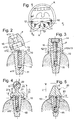
- a plurality of implants indicated diagrammatically by 10 are implanted in the mandibular bone A of a patient in positions that are as far as possible equidistant in order to constitute as many anchorage points of a one-piece titanium framework of the type mentioned in the introductory part of the description.
- six implants are provided in the mandibular bone, but it is intended that the method of the invention is also equally valid for application to the maxillary bone and with a number of implants other than six.
- the opposite end or head end has a bearing surface 12 intended to act as an abutment surface for a mating surface 13 present on the framework F ( Figures 2 and 3); this surface of the framework is that which the present invention intends to machine accurately in order that it engages "passively" with the bearing surface 12 of the implant on tightening of a screw 14 which engages in a central vertical hole 15 formed in the head of the implant 10 and in a corresponding hole 16 of the framework.
- Figure 2 shows diagrammatically a "misfit” state, which the invention proposes to avoid.
- Figure 3 illustrates a state of " passive fit” between the surfaces 12 and 13 which mate with one another, so that the tightening of the screw 14 which connects the framework in a stable manner to one of the implants does not induce residual tensions as discussed in the introductory part of the description.
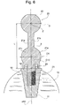
- each implant 10 there is temporarily associated a respective gauge indicated as a whole by 20 ( Figures 4 and 5), which is of a shape and dimensions that are predetermined and which make it possible to determine exactly the position and orientation of the bearing surfaces 12 of the implants and to acquire easily, by means of photographic or photogrammetric measurements, the data regarding position and orientation which will then be transferred to a numerically controlled milling apparatus which will provide, on the framework F, surfaces 13 mating with the bearing surfaces 12.
- each gauge comprises a substantially cylindrical base portion with a straight, externally threaded stem 21 and a spherical head portion 22.
- the threaded stem 21 is screwed into the central hole 15 of an implant as far as a predetermined height, which may be determined by the abutment of a transverse or horizontal shoulder 23 formed by the gauge 20 against the surface 12 of the implant.
- the gauge is configured, in the screwed-in or abutment state, the spherical head 22 and a connecting portion 21a for connection to the stem 21 protrude beyond the edge of the gum and are therefore easily visible to anyone observing the oral cavity, while the bearing surface 12 of the implant is generally covered by the edge of the gum to anyone observing the patient frontally.
- the images obtained make it possible to establish accurately the position (and more particularly the co-ordinates x, y, z) of the centres Z of all the spherical heads.
- the stems 21 of each gauge, the connecting portions 21a of which are at least partly visible in the installed state, make it possible to establish, for each implant, the direction of the "longitudinal" axis a12 which passes through the centre Z of the spherical head and through the geometric centre C12 of the bearing surface 12 of the implant.
- the fixed distance L between the centre Z of the spherical head and the transverse shoulder 23 bearing on the surface 12 of the implant is known.
- the distance L is equivalent to the distance between the centre Z of the spherical head and the geometric centre C12 of the bearing surface 12 of an implant. It is therefore possible to determine precisely the position of the geometric centre C12 of the bearing surface 12 of each implant and the orientation of that surface (this orientation is perpendicular in each implant to the longitudinal axis a12 of the respective gauge).
- various photogrammetric instruments and techniques for three-dimensional measurements can be used, provided that they are capable of determining unambiguously the arrangement and orientation of the aforesaid surfaces.
- the co-ordinates of the centre of a spherical head and the vectorial components of the longitudinal axis of the gauge at least two images of the oral cavity from at least two different angles must be acquired.
- the spherical, or at least partly spherical, shape of the head 22 is advantageous, since it allows the position of its centre Z to be determined from any observation point.
- the invention is not limited to the embodiment described and illustrated here, which is to be regarded as an example of the method for the construction of a framework for dental prostheses.
- the invention is capable of modifications relating to shape and arrangement of parts, constructional details and function.
- Persons skilled in the art will recognise that the position and orientation of the bearing surface of an implant may be determined by using gauges of a shape different from those illustrated by way of example. For example, as illustrated in Fig. 5, gauges of conical or frustoconical shape may be used, the vertex Z of which (equivalent to the centre of the spherical head of the example illustrated in Fig. 4) and the axis of which make it possible to establish in space a point, a direction and a distance L from the bearing surface 12 of an implant.
- Figure 6 shows a preferred embodiment of the gauges 20, wherein parts and elements identical or similar to those described with reference to the preceding figures have been assigned the same numerical references.
- This variant differs from that described previously in Figure 4 in that the connecting portion 21a has a first straight portion 21b and a spherical body 21c, located in proximity to the transverse shoulder 23, and having a centre Z1 and diameter D1 suitably equal to the diameter D of the head 22.
- the centre Z1 which advantageously (but not necessarily) lies on the axis a12, and the centre Z make it possible to establish precisely the position of the geometric centre C12 and the orientation of the bearing surface 12.
Landscapes
- Health & Medical Sciences (AREA)
- Oral & Maxillofacial Surgery (AREA)
- Dentistry (AREA)
- Epidemiology (AREA)
- Life Sciences & Earth Sciences (AREA)
- Animal Behavior & Ethology (AREA)
- General Health & Medical Sciences (AREA)
- Public Health (AREA)
- Veterinary Medicine (AREA)
- Orthopedic Medicine & Surgery (AREA)
- Dental Prosthetics (AREA)
- Dental Tools And Instruments Or Auxiliary Dental Instruments (AREA)
Applications Claiming Priority (2)
| Application Number | Priority Date | Filing Date | Title |
|---|---|---|---|
| IT000575A ITTO20030575A1 (it) | 2003-07-25 | 2003-07-25 | Procedimento per la fabbricazione di travate di protesi dentarie del tipo avvitato ad una pluralita' di impianti osteo-integrati nell'osso mandibolare o mascellare. |
| ITTO20030575 | 2003-07-25 |
Publications (2)
| Publication Number | Publication Date |
|---|---|
| EP1500380A2 true EP1500380A2 (fr) | 2005-01-26 |
| EP1500380A3 EP1500380A3 (fr) | 2005-11-09 |
Family
ID=33485534
Family Applications (1)
| Application Number | Title | Priority Date | Filing Date |
|---|---|---|---|
| EP04425318A Withdrawn EP1500380A3 (fr) | 2003-07-25 | 2004-05-05 | Méthode de fabrication d'un préforme prothétique destinée à être visée sur des implants dentaires |
Country Status (3)
| Country | Link |
|---|---|
| US (1) | US20050019728A1 (fr) |
| EP (1) | EP1500380A3 (fr) |
| IT (1) | ITTO20030575A1 (fr) |
Cited By (5)
| Publication number | Priority date | Publication date | Assignee | Title |
|---|---|---|---|---|
| EP2103276A1 (fr) * | 2008-03-19 | 2009-09-23 | Nobel Biocare Services AG | Repositionnement de composants associés aux procédures chirurgicales crâniennes chez un patient |
| WO2010097214A1 (fr) * | 2009-02-26 | 2010-09-02 | Nobel Biocare Services Ag | Dispositif pour indiquer la position et l'orientation d'un implant dentaire |
| EP2206470A3 (fr) * | 2008-05-21 | 2011-01-12 | Hubert L. Gooch | Systèmes pour le traitement médical de tissus structurels |
| US8905757B2 (en) | 2012-12-03 | 2014-12-09 | E. Kats Enterprises Ltd. | Method and apparatus for measuring a location and orientation of a plurality of implants |
| US10206757B2 (en) | 2007-01-10 | 2019-02-19 | Nobel Biocare Services Ag | Method and system for dental planning and production |
Families Citing this family (14)
| Publication number | Priority date | Publication date | Assignee | Title |
|---|---|---|---|---|
| DE10010073B4 (de) * | 2000-02-28 | 2005-12-22 | Fraunhofer-Gesellschaft zur Förderung der angewandten Forschung e.V. | Verankerung für implantierbare Herzklappenprothesen |
| US20090305185A1 (en) * | 2008-05-05 | 2009-12-10 | Lauren Mark D | Method Of Designing Custom Articulator Inserts Using Four-Dimensional Data |
| DE102006052419A1 (de) * | 2006-11-07 | 2008-05-08 | Aepsilon Rechteverwaltungs Gmbh | Verfahren zum Erfassen von Implantaten |
| US8100692B2 (en) * | 2007-10-19 | 2012-01-24 | Cagenix Incorporated | Dental framework |
| EP2218423B1 (fr) * | 2009-02-12 | 2012-05-02 | Straumann Holding AG | Détermination de la position et de l'orientation d'un implant dentaire |
| WO2011078877A1 (fr) * | 2009-12-11 | 2011-06-30 | Cortex Dental Implants Industries Ltd. | Implant à ailette |
| EP2392290A3 (fr) * | 2010-06-04 | 2013-08-14 | Andreas Klar | Procédé de fabrication de structures de prothèses dentaires portées par des implants |
| US9289282B2 (en) | 2011-05-31 | 2016-03-22 | Edwards Lifesciences Corporation | System and method for treating valve insufficiency or vessel dilatation |
| EP2865352A4 (fr) * | 2012-06-26 | 2016-01-20 | G C Dental Ind Corp | Gabarit de numérisation |
| US9452034B1 (en) | 2012-10-23 | 2016-09-27 | Javier Urquiola | Hybrid passively fitting prosthodontic frameworks |
| EP2842493B1 (fr) | 2013-08-30 | 2016-04-06 | Zfx GmbH | Corps de référence intra-orale |
| US10426711B2 (en) | 2014-05-08 | 2019-10-01 | Cagenix, Inc. | Dental implant framework |
| US10980618B2 (en) | 2014-05-08 | 2021-04-20 | Cagenix, Inc. | Dental framework and prosthesis |
| US11364101B2 (en) | 2018-12-03 | 2022-06-21 | Cagenix, Inc. | Dental implant framework |
Family Cites Families (5)
| Publication number | Priority date | Publication date | Assignee | Title |
|---|---|---|---|---|
| US5055047A (en) * | 1990-10-17 | 1991-10-08 | Names Curtis D | Metal impression confirmation system for dental implants |
| US5208845A (en) * | 1992-02-04 | 1993-05-04 | Gelb David A | Radiographic depth gauge |
| JPH0824685B2 (ja) * | 1992-11-25 | 1996-03-13 | 株式会社江川 | インプラント構造体の測定方法およびその測定装置 |
| NL9301308A (nl) * | 1993-07-26 | 1995-02-16 | Willem Frederick Van Nifterick | Werkwijze voor het vastzetten van een tandprothese op implantaten in het kaakbeen van een patiënt en middel te gebruiken daarbij. |
| GB9924959D0 (en) * | 1999-10-21 | 1999-12-22 | Sethi Ashok | Implant alignment |
-
2003
- 2003-07-25 IT IT000575A patent/ITTO20030575A1/it unknown
-
2004
- 2004-05-05 EP EP04425318A patent/EP1500380A3/fr not_active Withdrawn
- 2004-05-20 US US10/849,248 patent/US20050019728A1/en not_active Abandoned
Cited By (11)
| Publication number | Priority date | Publication date | Assignee | Title |
|---|---|---|---|---|
| US10206757B2 (en) | 2007-01-10 | 2019-02-19 | Nobel Biocare Services Ag | Method and system for dental planning and production |
| EP2103276A1 (fr) * | 2008-03-19 | 2009-09-23 | Nobel Biocare Services AG | Repositionnement de composants associés aux procédures chirurgicales crâniennes chez un patient |
| WO2009115283A1 (fr) * | 2008-03-19 | 2009-09-24 | Nobel Biocare Services Ag | Repositionnement d’éléments liés à des interventions chirurgicales crâniennes chez un patient |
| US8805658B2 (en) | 2008-03-19 | 2014-08-12 | Nobel Biocare Services Ag | Repositioning of components related to cranial surgical procedures in a patient |
| EP2206470A3 (fr) * | 2008-05-21 | 2011-01-12 | Hubert L. Gooch | Systèmes pour le traitement médical de tissus structurels |
| WO2010097214A1 (fr) * | 2009-02-26 | 2010-09-02 | Nobel Biocare Services Ag | Dispositif pour indiquer la position et l'orientation d'un implant dentaire |
| CN102307539A (zh) * | 2009-02-26 | 2012-01-04 | 诺贝尔生物服务公司 | 用于表示牙齿种植体的位置和取向的装置 |
| CN102307539B (zh) * | 2009-02-26 | 2014-03-12 | 诺贝尔生物服务公司 | 用于表示牙齿种植体的位置和取向的装置 |
| EP2712573A3 (fr) * | 2009-02-26 | 2015-05-06 | Nobel Biocare Services AG | Dispositif pour indiquer la position et l'orientation d'un implant dentaire |
| AU2010219145B2 (en) * | 2009-02-26 | 2015-11-12 | Nobel Biocare Services Ag | Device for indicating the position and orientation of a dental implant |
| US8905757B2 (en) | 2012-12-03 | 2014-12-09 | E. Kats Enterprises Ltd. | Method and apparatus for measuring a location and orientation of a plurality of implants |
Also Published As
| Publication number | Publication date |
|---|---|
| ITTO20030575A1 (it) | 2005-01-26 |
| EP1500380A3 (fr) | 2005-11-09 |
| US20050019728A1 (en) | 2005-01-27 |
Similar Documents
| Publication | Publication Date | Title |
|---|---|---|
| EP1500380A2 (fr) | Méthode de fabrication d'un préforme prothétique destinée à être visée sur des implants dentaires | |
| Arcuri et al. | Influence of implant scanbody material, position and operator on the accuracy of digital impression for complete-arch: A randomized in vitro trial | |
| Chia et al. | In Vitro Three-Dimensional Accuracy of Digital Implant Impressions: The Effect of Implant Angulation. | |
| Jemt et al. | Prosthesis misfit and marginal bone loss in edentulous implant patients. | |
| Tan et al. | Comparison of Three-Dimensional Accuracy of Digital and Conventional Implant Impressions: Effect of Interimplant Distance in an Edentulous Arch. | |
| Giménez et al. | Accuracy of a digital impression system based on active wavefront sampling technology for implants considering operator experience, implant angulation, and depth | |
| Jemt et al. | Precision of CNC-milled titanium frameworks for implant treatment in the edentulous jaw. | |
| Gedrimiene et al. | Accuracy of digital and conventional dental implant impressions for fixed partial dentures: A comparative clinical study | |
| Chew et al. | Three-Dimensional Accuracy of Digital Implant Impressions: Effects of Different Scanners and Implant Level. | |
| Giménez et al. | Accuracy of two digital implant impression systems based on confocal microscopy with variations in customized software and clinical parameters. | |
| Vág et al. | A novel method for complex three-dimensional evaluation of intraoral scanner accuracy | |
| AU2006306462B2 (en) | Methods for manufacturing dental implant components | |
| Jemt | In vivo measurements of precision of fit involving implant-supported prostheses in the edentulous jaw. | |
| Jemt et al. | Accuracy of implant‐supported prostheses in the edentulous jaw. Analysis of precision of fit between cast gold‐alloy frameworks and master casts by means of a three‐dimensional photogrammetric technique. | |
| Mutwalli et al. | Trueness and precision of three‐dimensional digitizing intraoral devices | |
| US7988449B2 (en) | Healing components for use in taking impressions and methods for making the same | |
| EP1229853B1 (fr) | Composants de cicatrisation a utiliser lors de la prise d'empreinte | |
| US7362890B2 (en) | Registration of 3-D imaging of 3-D objects | |
| Ciocca et al. | In vitro assessment of the accuracy of digital impressions prepared using a single system for full-arch restorations on implants | |
| KR102455964B1 (ko) | 스캔용 지그 및 임플란트 등의 공간적 위치를 특정하는 방법 및 시스템 | |
| US20180085202A1 (en) | Methods, systems and accessories useful for procedures relating to dental implants | |
| US20100255445A1 (en) | Assisted dental implant treatment | |
| US20060019219A1 (en) | Method to determine position and orientation of the axis of a dental implant disposed directly in the mouth of the patient as well as a mounting piece | |
| US20180206950A1 (en) | Dental implant prosthesis using digital library and method for manufacturing same | |
| Braian et al. | Tolerance measurements on internal-and external-hexagon implants. |
Legal Events
| Date | Code | Title | Description |
|---|---|---|---|
| PUAI | Public reference made under article 153(3) epc to a published international application that has entered the european phase |
Free format text: ORIGINAL CODE: 0009012 |
|
| AK | Designated contracting states |
Kind code of ref document: A2 Designated state(s): AT BE BG CH CY CZ DE DK EE ES FI FR GB GR HU IE IT LI LU MC NL PL PT RO SE SI SK TR |
|
| AX | Request for extension of the european patent |
Extension state: AL HR LT LV MK |
|
| RAP1 | Party data changed (applicant data changed or rights of an application transferred) |
Owner name: IRON SRL |
|
| PUAL | Search report despatched |
Free format text: ORIGINAL CODE: 0009013 |
|
| AK | Designated contracting states |
Kind code of ref document: A3 Designated state(s): AT BE BG CH CY CZ DE DK EE ES FI FR GB GR HU IE IT LI LU MC NL PL PT RO SE SI SK TR |
|
| AX | Request for extension of the european patent |
Extension state: AL HR LT LV MK |
|
| AKX | Designation fees paid | ||
| REG | Reference to a national code |
Ref country code: DE Ref legal event code: 8566 |
|
| STAA | Information on the status of an ep patent application or granted ep patent |
Free format text: STATUS: THE APPLICATION IS DEEMED TO BE WITHDRAWN |
|
| 18D | Application deemed to be withdrawn |
Effective date: 20060510 |