EP1499006B1 - Vorrichtung zum potentialgetrennten Umwandeln einer ersten Spannung in eine zweite Spannung zum Messen von Impedanzen und Admittanzen an biologischen Geweben - Google Patents
Vorrichtung zum potentialgetrennten Umwandeln einer ersten Spannung in eine zweite Spannung zum Messen von Impedanzen und Admittanzen an biologischen Geweben Download PDFInfo
- Publication number
- EP1499006B1 EP1499006B1 EP04016860A EP04016860A EP1499006B1 EP 1499006 B1 EP1499006 B1 EP 1499006B1 EP 04016860 A EP04016860 A EP 04016860A EP 04016860 A EP04016860 A EP 04016860A EP 1499006 B1 EP1499006 B1 EP 1499006B1
- Authority
- EP
- European Patent Office
- Prior art keywords
- motor
- generator
- voltage
- shaft
- tension
- Prior art date
- Legal status (The legal status is an assumption and is not a legal conclusion. Google has not performed a legal analysis and makes no representation as to the accuracy of the status listed.)
- Expired - Lifetime
Links
Images


Classifications
-
- A—HUMAN NECESSITIES
- A61—MEDICAL OR VETERINARY SCIENCE; HYGIENE
- A61B—DIAGNOSIS; SURGERY; IDENTIFICATION
- A61B5/00—Measuring for diagnostic purposes; Identification of persons
- A61B5/05—Detecting, measuring or recording for diagnosis by means of electric currents or magnetic fields; Measuring using microwaves or radio waves
- A61B5/053—Measuring electrical impedance or conductance of a portion of the body
-
- H—ELECTRICITY
- H02—GENERATION; CONVERSION OR DISTRIBUTION OF ELECTRIC POWER
- H02M—APPARATUS FOR CONVERSION BETWEEN AC AND AC, BETWEEN AC AND DC, OR BETWEEN DC AND DC, AND FOR USE WITH MAINS OR SIMILAR POWER SUPPLY SYSTEMS; CONVERSION OF DC OR AC INPUT POWER INTO SURGE OUTPUT POWER; CONTROL OR REGULATION THEREOF
- H02M5/00—Conversion of AC power input into AC power output, e.g. for change of voltage, for change of frequency, for change of number of phases
- H02M5/02—Conversion of AC power input into AC power output, e.g. for change of voltage, for change of frequency, for change of number of phases without intermediate conversion into DC
- H02M5/32—Conversion of AC power input into AC power output, e.g. for change of voltage, for change of frequency, for change of number of phases without intermediate conversion into DC by dynamic converters
-
- A—HUMAN NECESSITIES
- A61—MEDICAL OR VETERINARY SCIENCE; HYGIENE
- A61B—DIAGNOSIS; SURGERY; IDENTIFICATION
- A61B5/00—Measuring for diagnostic purposes; Identification of persons
- A61B5/41—Detecting, measuring or recording for evaluating the immune or lymphatic systems
- A61B5/413—Monitoring transplanted tissue or organ, e.g. for possible rejection reactions after a transplant
Definitions
- the invention relates to a device for electrically converting a first voltage to a second voltage, as generally, in truly floating, i. non-potential measuring instruments, e.g. in medical technology, and in particular in connection with the measurement of impedances and admittances on biological tissues, in particular on the human body, can be used for the power supply of the electronic measuring device or devices.
- the impedance or admittance measurement on biological tissues allows statements about their condition, if suitable frequencies are used.
- suitable frequencies e.g. B.
- valuable information can be obtained in the course of and after heart surgery because of the impedance measurement for the diagnosis.
- organ transplants for the determination of ischemia-related damage and / or recovery of the transplanted organ.
- the network Since the network, to which the energy required for the measuring devices is taken almost exclusively, has a voltage which in any case must be converted into one or more voltages suitable for the measuring instruments used, it makes sense in one step or a single module to combine the conversion of a voltage in the other (s) voltage (s) with the potential separation.
- An output circuit 3 of such a device 1 with the terminals 7 and 8 is a the smallest possible capacity 9 with respect to the isolated input circuit 2, which is connected via the terminals 5 and 6 to the network, and also a small capacity 11 as possible to earth (ground).
- no disturbances in particular HF disturbances
- transformers are used for this purpose in such power supply devices, as shown in Fig. 2.
- the aforementioned safety regulations are very stringent and it is difficult to keep the leakage currents, and in particular the dielectric displacement currents due to the capacitances 9a and 9b of the windings 12 and 13, below 10 ⁇ A.
- grounding of the transformer core 14 and particular arrangement of the windings achieves a relatively small capacitance between the primary and secondary windings, it does increase the capacitances 11a and 11b between the secondary winding 13 and ground.
- a closed circuit results, for example, when the patient to whom an impedance is to be measured is connected (if only capacitively) to earth (ground), and the meters are operated via the network, which also has a ground connection.
- motor generator set As "motor generator set” is in the U.S. Patent 2,327,874 given as a way to power a portable electromedical device, but without reference to the specific requirements of the electrical insulation between the motor and generator and the requirement of a particularly low capacity of the generator side to ground and the drive side, as well as the isolation against electrical mains side noise and bridging short-term Power failures during mains operation.
- EP 0 480 078 A1 which discloses a measuring device with non-electrical signal and energy transmission to a remote location, is an isolated shaft motor-generator system mentioned in the field of power engineering, but at the "mechanical failure susceptibility" and the signs of wear on moving parts are criticized. Naturally, no information has been provided about critical parameters to be observed in the field of medical technology.
- This latter condition is not met in commercially available DC / DC or AC / DC converters. Rather, they have common mode noise on the output side and considerable high frequency magnetic stray fields that can interfere with sensitive circuit parts of a measuring device. Common mode noise can, in principle, be reduced by means of a capacitor of appropriate capacitance (and withstand voltage) interconnecting the input and output side masses. However, this measure would be the one for a perfect impedance measurement on People counteract the need for the least possible capacity (9 in Fig. 1) between the input and output side of the power supply directly.
- the device should have a simple structure and thus be relatively inexpensive and yet reliably comply with the very strict statutory safety regulations, eg. B. that the output side leakage current is not greater than 10 uA and that a safety barrier of 4 kV eff is guaranteed.
- the invention provides that at least a portion of the coupling device between the motor and the generator consists of an electrically insulating plastic material such as nylon, Trovidur® (trade name) or polystyrene or a ceramic material such as Degussit® (trade name) or zirconium oxide.
- an electrically insulating plastic material such as nylon, Trovidur® (trade name) or polystyrene or a ceramic material such as Degussit® (trade name) or zirconium oxide.
- These are generally a shaft or shaft section, but also the motor or generator shaft, or e.g. the belt of a belt drive or a shaft coupling, e.g. an elastic coupling, if not a continuous high-strength ceramic shaft of zirconium oxide in particular, can be used.
- the capacity of the generator with respect to mass should be less than about 10 pF, preferably 8 pF, in particular 5 pF.
- the second voltage is usually a low voltage for operating electronic circuits of a measuring device.
- each subunit of a shaft is seen in its longitudinal course.
- the shaft is a constant diameter cylindrical rod
- a portion of the shaft is a cylinder that may have the same cross section but not quite as long as the rod.
- a portion of the shaft is not to be understood as a partial cylinder, which has only a smaller diameter than the shaft but is not made of insulating material.
- the electrically insulating portion of the shaft or the formation of a separate connecting shaft of electrically insulating material with a low dielectric constant a high potential barrier between the motor and generator is made possible, which prevents leakage currents can flow from the motor to the generator or vice versa.
- the capacitive coupling between the motor and generator is kept sufficiently small by appropriate distance.
- the device according to the invention can also be formed by connecting the shaft of the motor to the shaft of the generator with a separate connection shaft, the separate shaft consisting of insulating material and the electrically insulating section forms.
- an electrically insulating portion 18 ( Figure 5) may be flanged to the two shafts of the motor or generator. It is also possible to draw a connecting tube of electrically insulating material onto the two shafts of motor and generator, so that the torque is transmitted via the hose.
- the mechanical coupling of the two shafts may also be effected via a belt drive comprising two pulleys mounted on the respective shafts and a belt of electrically insulating material circulating on these pulleys.
- the pulleys can - to reduce the electrical capacitance - also be made of a non-conductive material of lowest dielectric constant.
- the drive motor is operated by means of a power or voltage source.
- the rotation of its shaft is transmitted electrically isolated to the generator. This generates the second voltage.
- the second voltage is then the voltage by which the measuring devices are operated, which are connected via lines on the human body to or at which the impedance is to be measured.
- the drive motor may be an AC motor. However, it can also be a DC motor, with collector or with electronic commutation, which is operated by a rectifier or a battery. This may be, for example, a conventional car battery. If these were connected directly to the measuring devices, since the battery is in each case at least capacitively coupled to earth (ground), the impedance measurement on the body would become faulty, especially at higher frequencies.
- the drive motor does not necessarily have to be an electric motor;
- the drive would be possible by a motor operated by compressed air (turbine).
- the generator may be a DC generator, but also an AC generator.
- a permanent magnet rotating in the generator, a permanent magnet, which acts as a rotor, in a single- or multi-phase stator.
- a three-phase AC voltage generated since after rectification receives a stream of low ripple, which requires little smoothing (leveling of the ripple).
- the capacity of at most about 10 pF, in particular 5 pF, is to be respected.
- the device is nothing more than a special type of power supply.
- the combination of motor and generator according to the invention is well known in the art, as stated at the outset, and others. as a rotating converter or motor generator. Apart from the difference according to the invention, that a section of the shaft consists of insulating material of very low dielectric constant, these converters, however, are usually concerned with quite different orders of magnitude of voltages and, in particular, powers, e.g. B. in forming stations.
- the first voltage is usually a mains AC voltage of 230 V or 110 V or 100 V or a battery voltage of 12 V or 24 V.
- the second voltage is of the order of 5 to 15 V DC or AC voltage.
- the device according to the invention is also substantially smaller than the known power converters, since only small electrical powers are to be made available for the measuring devices.
- a power output of 50 W e.g. the longest dimensions of the motor-generator system are 20 cm in diameter, less than 4 cm, or significantly less, depending on the required output power.
- the waves or the connecting shaft should not be too short, since the capacity between the metallic parts of the input and output side should be less than 5 pF if possible.
- the exposed area of the shaft ie the area that emerges from the part projecting the motor, which is responsible for the drive of the shaft and not yet protrudes into the stator of the generator, so the part that is outside of the (actual) engine and the (actual) generator should therefore be at least as long as the engine or be the generator, for. B. 5 to 10 cm.
- the portion is substantially as long as the area of the shaft which is outside the motor and the generator.
- the coupling device is a ceramic shaft mounted at its two ends, on which - spaced from one another - a motor armature surrounded by a stator and a generator armature surrounded by a stator are provided.
- the housings of the stators are sufficiently far apart to be able to comply with the electrical conditions.
- the device according to the invention is used in a room in which patients are treated, it is advantageous if the device operates as quietly as possible. Due to the rotational movement, a buzzing noise can be generated.
- the device which, as mentioned above, need not be particularly large, is incorporated in a sound-proofing case, i. H. in a housing that allows as little sound as possible to escape to the outside.
- the device can also be integrated into the meter to be fed by it.
- the device according to the invention is characterized in that it has a high potential barrier and a high insulation resistance between input and output, that it has a small electrical capacitance of the output (ie the secondary circuit) to ground, that suppresses primary side noise and even high-frequency interference be generated. Short interruptions of the power supply can be bridged esp. By a flywheel. It is therefore not only suitable for the power supply of measuring instruments in medical technology but also in related fields such as biotechnology and pharmaceutical technology.
- one of a first voltage supplied via the terminals 5 and 6 rotates operated drive motor 15 via a completely made of an electrically insulating material shaft 17 a seated on her rotor of a generator 16 which generates the second voltage, which is available via the terminals 7 and 8 of the generator for powering a meter.
- a belt drive 21 between the usual, made of metal shaft of the drive motor 15 and the also usual, consisting of metal shaft of the generator 16 is provided.
- the first embodiment may be modified such that not the entire shaft 17 is made of an insulating material, but only a portion 18, as shown in the third embodiment of FIG. 5.
- the portion 18 is shown thickened relative to the shaft to represent a better quality potential separation.
- a fan 23 see Fig. 3, for a forced cooling of the device and / or an (integrated) measuring device are applied.
- Short-term power failures can be bridged by a flywheel 24 with sufficient moment of inertia on an extended motor or generator shaft, s. Fig. 3.
- Fig. 5 is instead of an AC voltage - according to Fig. 3, depending on the generator type an AC or DC voltage applied to the terminals 7 and 8 - after rectification in a rectifier 25 and a filter member 26, a DC voltage to the Terminals 7a and 8a available.
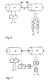
- the device according to the invention of a fourth embodiment according to FIG. 6 comprises as main components a (brushless) DC motor 15, which can be operated, for example, from a car battery or with rectified voltage from the mains, and an AC voltage generator 16.
- the drive motor 15 drives with its shaft via a , Preferably flexible coupling 18a to an intermediate shaft 22 of insulating material, which drives the shaft of the generator 16 via a second, esp. Also flexible coupling 18b.
- conventional technology is used except for the intermediate shaft.
- the located within the motor 15 part of the motor shaft carries a permanent magnet as a rotor.
- the section of the generator shaft located within the generator 16 also carries a permanent magnet and runs in a three-phase stator.
- the intermediate shaft 22 may be made of conductive material instead of an insulating material, e.g. made of metal. But then the flexible couplings 18a and 18b must be made of insulating material or otherwise insulating.
- the intermediate shaft 22 is a (not necessarily) cylindrical rod, that is, it usually has a circular cross-section.
- the insulating intermediate shaft 22 can be advantageously made of Trovidur®, d. H. an electrically insulating material to be made. It has about the same length as the shaft sections protruding from the engine and the generator.
- the clutches 18a and 18b and the insulating intermediate shaft 22 or the insulating portion 18 of the shaft 17 are replaced by an elastic tube mounted on the shaft ends of the motor and generator, see FIG. Fig. 5.
- the generator voltage is supplied via a three-phase transformer 27 (FIG. 6) with two separate secondary windings to two different rectifiers 28 and 31 and sieve members and voltage stabilizers 29 and 32, wherein 29 are connected to the terminals 30 of the voltage stabilizer 29 voltages of +15 V and -. 15 V from the zero point of the output side can be removed, and at the terminals 33 of the voltage stabilizer 32, an independent voltage of 5 V can be removed.
- a three-phase transformer 27 (FIG. 6) with two separate secondary windings to two different rectifiers 28 and 31 and sieve members and voltage stabilizers 29 and 32, wherein 29 are connected to the terminals 30 of the voltage stabilizer 29 voltages of +15 V and -. 15 V from the zero point of the output side can be removed, and at the terminals 33 of the voltage stabilizer 32, an independent voltage of 5 V can be removed.
- the device according to the invention is very small; e.g. for a power of about 50 W, the drive motor has a length of 6 cm, and the diameter of the cylindrically shaped engine is 3.2 cm.
- the generator has substantially the same dimensions.
- the lying outside of the motor 15 and the generator 16, exposed in the figure (so to speak, "in the air") lying portion of the shaft has a length of about 10 cm.
- the insulating shaft 22 has a length of about 5 cm.
- the drive motor 15 ( Figure 6) may also be equipped with a motor control 34 which keeps the speed of the device constant independent of fluctuations in the supply voltage and the load.
- the output voltage of the rectifier 25a can be removed via, for example, a linear optocoupler 35 and kept at a constant value by means of an additional regulator 36.
- controller 36 can detect and signal overload and optionally switch off the drive motor 15.
- the entire device can be integrated with the meter to be fed into a housing or housed in a small soundproof housing, which has vents, so that the heat generated by the engine and the generator can escape, but still for a Soundproofing can provide.
Landscapes
- Health & Medical Sciences (AREA)
- Life Sciences & Earth Sciences (AREA)
- Engineering & Computer Science (AREA)
- Heart & Thoracic Surgery (AREA)
- Molecular Biology (AREA)
- Physics & Mathematics (AREA)
- Nuclear Medicine, Radiotherapy & Molecular Imaging (AREA)
- Biophysics (AREA)
- Pathology (AREA)
- Biomedical Technology (AREA)
- Power Engineering (AREA)
- Medical Informatics (AREA)
- Radiology & Medical Imaging (AREA)
- Surgery (AREA)
- Animal Behavior & Ethology (AREA)
- General Health & Medical Sciences (AREA)
- Public Health (AREA)
- Veterinary Medicine (AREA)
- Connection Of Motors, Electrical Generators, Mechanical Devices, And The Like (AREA)
- Measurement And Recording Of Electrical Phenomena And Electrical Characteristics Of The Living Body (AREA)
- Measurement Of Resistance Or Impedance (AREA)
- Investigating Or Analyzing Materials By The Use Of Electric Means (AREA)
Description
- Die Erfindung betrifft eine Vorrichtung zum potentialgetrennten Umwandeln einer ersten Spannung in eine zweite Spannung, wie sie, allgemein, bei wirklich floatenden, d.h. nicht auf ein Potential bezogenen Messgeräten, z.B. in der Medizintechnik, und insbesondere im Zusammenhang mit der Messung von Impedanzen und Admittanzen an biologischen Geweben, insbesondere am menschlichen Körper, für die Stromversorgung des oder der elektronischen Messgeräte einsetzbar ist.
- Die Impedanz- oder Admittanzmessung an biologischen Geweben, z. B. am menschlichen Körper, ermöglicht Aussagen über deren Zustand, wenn geeignete Frequenzen verwendet werden. Beispielsweise können bei Herzpatienten im Verlauf von und nach Herzoperationen aufgrund der Impedanzmessung für die Diagnose wertvolle Aussagen gewonnen werden. Dasselbe gilt auch bei Organtransplantationen zur Bestimmung der Ischämie-bedingten Schädigung und/oder Wiedererholung des transplantierten Organs.
- Für die Messgeräte für elektrische Messungen an inneren Organen des Menschen gelten strenge gesetzliche Sicherheitsvorschriften. Insbesondere muss gewährleistet sein, dass kein Fehlerstrom, der 10 µA überschreitet, über den Menschen abfließt, und dass zwischen dem Netz, aus dem die verwendeten Messgeräte versorgt werden, und dem menschlichen Messobjekt eine Isolationsbarriere besteht, die einem Potentialunterschied von 4 kVeff standhält.
- Da das Netz, dem die für die Messgeräte notwendige Energie fast ausschließlich entnommen wird, eine Spannung aufweist, die ohnehin in eine oder mehrere für die verwendeten Messgeräte geeignete(n) Spannung(en) umgewandelt werden muss, bietet es sich an, in einem Schritt bzw. einer einzigen Baugruppe die Umwandlung der einen Spannung in die andere(n) Spannung(en) mit der Potentialtrennung zu kombinieren.
- Außer der Potentialtrennung gibt es weitere Anforderungen an eine Vorrichtung zur Stromversorgung eines Impedanzmessgerätes, wie sie in Fig. 1 dargestellt ist. Ein Ausgangskreis 3 einer solchen Vorrichtung 1 mit den Anschlüssen 7 und 8 soll eine möglichst kleine Kapazität 9 gegenüber dem potentialgetrennten Eingangskreis 2, der über die Anschlüsse 5 und 6 mit dem Netz verbunden ist, und eine ebenfalls möglichst kleine Kapazität 11 gegen Erde (Masse) aufweisen. Damit wird gewährleistet, dass das Messgerät auch bei höheren Frequenzen nicht auf Erde bzw. Masse bezogen ist, und folglich die (insbesondere hochfrequenten) Messhilfsströme, die vom Messgerät in den menschlichen Körper eingeleitet werden, nicht über diesen zur Erde abfließen, sondern mit dem Messgerät vollständig erfasst werden. Des weiteren sollen über eine Potentialbarriere 4 keine Störungen (insbesondere HF-Störungen) aus dem Netz auf den Ausgangskreis 3 übertragen werden.
- Herkömmlicherweise werden hierfür in solchen Stromversorgungsvorrichtungen Transformatoren eingesetzt, wie dies in Fig. 2 dargestellt ist. Die eingangs genannten Sicherheitsvorschriften sind jedoch sehr streng, und es ist schwierig, die Kriechströme und insbesondere die durch die Kapazität 9a und 9b der Wicklungen 12 und 13 bedingten dielektrischen Verschiebungsströme unter 10 µA zu halten. Durch Erdung des Transformatorkerns 14 und besondere Anordnung der Wicklungen erreicht man zwar eine relativ geringe Kapazität zwischen Primär- und Sekundärwicklung, erhöht jedoch die Kapazitäten 11a und 11b zwischen der Sekundärwicklung 13 und Erde. Ein geschlossener Stromkreis ergibt sich beispielsweise, wenn der Patient, an dem eine Impedanz gemessen werden soll, (wenn auch nur kapazitiv) mit der Erde (Masse) verbunden ist, und die Messgeräte über das Netz, das ebenfalls einen Masseanschluss hat, betrieben werden. Bei diesen kleinen Größenordnungen der Messströme üben die Kapazitäten zwischen den Wicklungen der Primär- und der Sekundärspule der Transformatoren sowie zwischen der Sekundärwicklung und Masse einen erheblichen störenden Einfluss aus. Bisher waren Verbesserungen darauf gerichtet, bei den Transformatoren die Kriechströme zu unterdrücken und die kapazitive Kopplung zu verringern. Nur mit viel Aufwand können die oben genannten Grenzwerte unterschritten werden. Dabei bleibt die Forderung nach geringer Kapazität des Sekundärkreises gegenüber Erde unerfüllt.
- Es ist zwar schon eine Vorrichtung zur Messung sowohl der Impedanz als auch des Gleichstrom-Widerstandes der Haut bekannt (
WO 00/01301 A1 - Die Erzeugung von Gleich- oder Wechselspannungen unterschiedlicher Größe, Kurvenform, Frequenz und/oder Modulation mittels eines Motor-Drehtransformator-Systems und zwar für therapeutische Zwecke ist bekannt (
US Patentschrift 1,908,688 ). Die erzeugte Spannung wird direkt über Elektroden an den menschlichen Körper angelegt. Trotz galvanischer Trennung der Ausgangsseite der Vorrichtung von der Eingangsseite (Netz) über induktive Kopplungen lässt sich die heute geforderte Spannungsfestigkeit von 4 kVeff und ein maximaler Fehlerstrom (Leckstrom) < 10 µA praktisch nicht und eine geringe elektrische Kapazität zwischen Eingangs- und Ausgangsseite schon gar nicht erreichen. Diese Vorrichtung dient ebenso wie die zuvor genannte zur Erzeugung von isolierten Messsignalen zur Anwendung am menschlichen Körper eignet sich aber nicht zur Stromversorgung von Messgeräten. - Die Verwendung einer Motor-Generator-Stromversorgung als "motor generator set" ist in der
US Patentschrift 2,327,874 als Möglichkeit zur Versorgung eines portablen elektromedizinischen Gerätes angegeben, jedoch ohne Hinweis auf die speziellen Erfordernisse der elektrische Isolation zwischen Motor und Generator und das Erfordernis einer besonders geringen Kapazität der Generatorseite gegenüber Masse und der Antriebsseite, sowie der Isolation gegenüber elektrischen netzseitigen Störungen und der Überbrückung kurzzeitiger Netzausfälle bei Netzbetrieb. - In
EP 0 480 078 A1 , die eine Messvorrichtung mit nichtelektrischer Signal- und Energieübertragung an einen entfernten Ort offenbart, ist ein Motor-Generator-System mit isolierter Welle im Bereich der Starkstromtechnik erwähnt, an dem jedoch die "große mechanische Störanfälligkeit" und die Verschleißerscheinungen bei bewegten Teilen bemängelt werden. Über bei der Messtechnik im Bereich der Medizin einzuhaltende kritische Parameter sind naturgemäß keine Angaben gemacht. - Es ist Aufgabe der Erfindung, eine Vorrichtung zum potentialgetrennten Umwandeln einer ersten Spannung, die auf Erde bezogen ist, in eine zweite bereitzustellen, die eine möglichst kleine Kapazität der Quelle der zweiten Spannung gegenüber Erde hat, die Störsignale auf der Eingangsseite nicht auf die Ausgangsseite überträgt und selbst keine zusätzlichen Störungen erzeugt. Diese letztere Bedingung ist bei kommerziell erhältlichen DC/DC- oder AC/DC-Wandlern nicht erfüllt. Sie weisen vielmehr Gleichtakt-Störspannungen auf der Ausgangsseite und beachtliche hochfrequente magnetische Streufelder auf, die auf empfindliche Schaltungsteile eines Messgerätes störend einwirken können. Gleichtaktstörungen können im Prinzip mittels eines Kondensators von entsprechender Kapazität (und Spannungsfestigkeit), der die Massen der Eingangs- und der Ausgangsseite miteinander verbindet, vermindert werden. Diese Maßnahme würde allerdings der für eine einwandfreie Impedanzmessung am Menschen notwendigen Forderung nach möglichst geringer Kapazität (9 in Fig. 1) zwischen Eingangs- und Ausgangsseite des Netzteils direkt zuwiderlaufen.
- Die Vorrichtung soll einen einfachen Aufbau haben und somit relativ preisgünstig sein und dennoch zuverlässig die sehr strengen gesetzlichen Sicherheitsvorschriften einhalten, z. B. dass der ausgangsseitige Leckstrom nicht größer als 10 µA wird und dass eine Sicherheitsbarriere von 4 kVeff gewährleistet ist.
- Diese Aufgabe ist erfindungsgemäß mit den Vorrichtungen nach Anspruch 1 gelöst. Vorteilhafte Ausgestaltungen ergeben sich aus Unteransprüchen.
- Die Erfindung sieht vor, dass zumindest ein Abschnitt der Kopplungsvorrichtung zwischen Motor und Generator aus elektrisch einem isolierendem Kunsthoffmaterial wie Nylon, Trovidur® (Markenname) oder Polystyrol oder einem Keramikmaterial wie Degussit® (Markenname) oder Zirkonoxid besteht. Dabei handelt es sich allgemeinen um eine Welle oder einen Wellenabschnitt, aber auch die Motor- oder die Generatorwelle, oder um z.B. den Riemen eines Riementriebs oder um eine Wellenkupplung, z.B. eine elastische Kupplung, wenn nicht eine durchgehende hochfeste keramische Welle aus insbesondere Zirkonoxid, eingesetzt werden kann. Die Kapazität des Generators gegenüber Masse soll weniger als etwa 10 pF, vorzugsweise 8 pF, insbesondere 5 pF, betragen.
- Die zweite Spannung ist im Regelfall eine Niederspannung zum Betrieb elektronischer Schaltungen eines Messgeräts.
- In den Ansprüchen wird mit Abschnitt der Welle jede Teileinheit einer Welle in ihrem Längsverlauf gesehen. Ist die Welle beispielsweise eine zylindrische Stange mit konstantem Durchmesser, so ist ein Abschnitt der Welle ein Zylinder, der denselben Querschnitt aufweisen kann, aber nicht ganz so lang wie die Stange ist. Unter einem Abschnitt der Welle ist nicht ein Teilzylinder zu verstehen, der nur einen geringeren Durchmesser als die Welle hat aber nicht aus isolierendem Material besteht.
- Durch den elektrisch isolierenden Abschnitt der Welle oder die Ausbildung einer gesonderten Verbindungswelle aus elektrisch isolierendem Material mit einer niedrigen Dielektrizitätskonstante wird eine hohe Potentialbarriere zwischen Motor und Generator ermöglicht, die verhindert, dass Kriechströme vom Motor zum Generator fließen können bzw. umgekehrt. Außerdem wird die kapazitive Kopplung zwischen Motor und Generator durch angemessenen Abstand voneinander ausreichend klein gehalten.
- Auch wenn hier nur von einer Welle die Rede ist, so kann man die erfindungsgemäße Vorrichtung auch bilden, indem man die Welle des Motors mit der Welle des Generators mit einer gesonderten Verbindungswelle verbindet, wobei die gesonderte Welle aus isolierendem Material besteht und den elektrisch isolierenden Abschnitt bildet. Beispielsweise kann ein elektrisch isolierender Abschnitt 18 (Fig. 5) an die beiden Wellen des Motors bzw. Generators geflanscht werden. Es ist auch möglich, einen verbindenden Schlauch aus elektrisch isolierendem Material, auf die beiden Wellen von Motor und Generator zu ziehen, so dass das Drehmoment über den Schlauch übertragen wird. Die mechanische Kopplung der beiden Wellen kann auch über einen Riementrieb erfolgen, der zwei Riemenscheiben umfasst, die auf den jeweiligen Wellen befestigt sind, und einen auf diesen Riemenscheiben umlaufenden Riemen aus elektrisch isolierendem Material. Die Riemenscheiben können - zur Verringerung der elektrischen Kapazität - ebenfalls aus einem nichtleitenden Material geringster Dielektrizitätskonstante gefertigt sein.
- Bei der erfindungsgemäßen Vorrichtung wird der Antriebsmotor mittels einer Energie- bzw. Spannungsquelle betrieben. Die Drehung seiner Welle wird elektrisch isoliert auf den Generator übertragen. Dieser erzeugt die zweite Spannung. Die zweite Spannung ist dann die Spannung, mittels derer die Messgeräte betrieben werden, die über Leitungen am menschlichen Körper, an oder in dem die Impedanz gemessen werden soll, angeschlossen werden.
- Der Antriebsmotor kann ein Wechselstrommotor sein. Er kann allerdings auch ein Gleichspannungsmotor sein, mit Kollektor oder mit elektronischer Kommutierung, der über einen Gleichrichter oder aus einer Batterie betrieben wird. Es kann sich hier beispielsweise um eine herkömmliche Autobatterie handeln. Würde diese direkt mit den Messgeräten verbunden, so würde, da die Batterie in jedem Fall zumindest kapazitiv mit Erde (Masse) verkoppelt ist, die Impedanzmessung am Körper insbesondere bei höheren Frequenzen fehlerhaft werden.
- Der Antriebsmotor muss nicht zwangsläufig ein Elektromotor sein;
z.B. wäre für einen speziellen Fall der Antrieb durch einen mit Druckluft betriebenen Motor (Turbine) möglich. - Der Generator kann ein Gleichspannungsgenerator sein, aber auch ein Wechselspannungsgenerator. In letzterem Fall dreht sich im Generator ein Permanentmagnet, der als Rotor fungiert, in einem ein- oder mehrphasigen Stator. Zweckmäßigerweise wird eine Dreiphasen-Wechselspannung erzeugt, da man nach Gleichrichtung einen Strom geringer Welligkeit erhält, der nur geringer Glättung (Einebnung der Welligkeit) bedarf. Auf die Verwirklichung der Kapazität von höchstens etwa 10 pF, insbesondere 5 pF, ist zu achten.
- Ist die erste Spannung eine Netzspannung und die zweite Spannung eine Gleichspannung, ist die Vorrichtung nichts anderes als eine besondere Art von Netzteil.
- Die erfindungsgemäße Kombination von Motor und Generator ist im Stand der Technik, wie eingangs ausgeführt, wohlbekannt, und zwar u.a. als rotierender Umformer oder Motor-Generator. Von dem erfindungsgemäßen Unterschied abgesehen, dass ein Abschnitt der Welle aus isolierendem Material sehr geringer Dielektrizitätskonstante besteht, geht es bei diesen Umformern jedoch üblicherweise um ganz andere Größenordnungen von Spannungen und insbesondere Leistungen, z. B. in Umformstationen. Bei der Vorrichtung nach der Erfindung ist die erste Spannung üblicherweise eine Netzwechselspannung von 230 V bzw. 110 V oder 100 V oder eine Batteriespannung von 12 V oder 24 V. Die zweite Spannung liegt in der Größenordnung von 5 bis 15 V Gleich- oder Wechselspannung. Das erfindungsgemäße Gerät ist auch wesentlich kleiner als die bekannten Leistungsumformer, da nur geringe elektrische Leistungen für die Messgeräte zur Verfügung zu stellen sind. Für eine Leistungsabgabe von 50 W können z.B. die längsten Abmessungen des Motor-Generator-Systems 20 cm betragen bei einem Durchmesser von weniger als 4 cm oder noch erheblich weniger, je nach der geforderten Ausgangsleistung.
- Die Wellen oder die Verbindungswelle sollte nicht allzu kurz sein, da die Kapazität zwischen den metallischen Teilen der Eingangs- und Ausgangsseite möglichst unter 5 pF sein soll. Der freiliegende Bereich der Welle, d. h. der Bereich, der aus dem Teil des Motors vorsteht, der für den Antrieb der Welle verantwortlich ist und noch nicht in den Stator des Generators hineinragt, also der Teil, der außerhalb des (eigentlichen) Motors und des (eigentlichen) Generators liegt, sollte daher mindestens genauso lang wie der Motor oder der Generator sein, z. B. 5 bis 10 cm.
- Eine lange Welle hat selbstverständlich nur dann Sinn, wenn der elektrisch isolierende Abschnitt möglichst lang ist. Bevorzugt ist der Abschnitt im wesentlichen so lang wie der Bereich der Welle, der außerhalb des Motors und des Generators liegt.
- Eine lange Welle lässt sich mir modernen keramischen Werkstoffen verwirklichen. Eine Ausführungsform der Erfindung sieht daher vor, dass die Kopplungseinrichtung eine an ihren beiden Enden gelagerte keramische Welle ist, auf der - voneinander beabstandet - ein von einem Stator umgebener Motoranker und ein von einem Stator umgebener Generatoranker vorgesehen sind. Die Gehäuse der Statoren sind ausreichend weit voneinander entfernt, um die elektrischen Bedingungen einhalten zu können.
- Da die erfindungsgemäße Vorrichtung in einem Raum eingesetzt wird, in dem Patienten behandelt werden, ist es von Vorteil, wenn die Vorrichtung möglichst leise arbeitet. Durch die Rotationsbewegung kann ein summendes Geräusch erzeugt werden. Vorzugsweise ist daher die Vorrichtung, die, wie oben erwähnt, nicht besonders groß sein muss, in ein schallabdichtendes Gehäuse eingebaut, d. h. in ein Gehäuse, das möglichst wenig Schall nach außen dringen lässt. Die Vorrichtung kann aber auch in das von ihr zu speisende Messgerät integriert werden.
- Die erfindungsgemäße Vorrichtung zeichnet sich dadurch aus, dass sie eine hohe Potentialbarriere und einen hohen Isolationswiderstand zwischen Ein- und Ausgang hat, dass sie eine geringe elektrische Kapazität des Ausgangs (d.h. des Sekundärkreises) gegen Masse aufweist, dass primärseitige Störungen unterdrückt und selbst keine hochfrequente Störungen erzeugt werden. Kurze Unterbrechungen der Stromversorgung lassen sich insb. durch ein Schwungrad überbrücken. Sie eignet sich daher nicht nur zur Stromversorgung von Messgeräten in der Medizintechnik sondern auch in verwandten Bereichen wie der Biotechnik und der pharmazeutischen Technik.
- Weitere Vorteile der Erfindung werden aus der nachfolgenden Beschreibung bevorzugter Ausführungsformen besser ersichtlich, die unter Bezug auf die beigefügte Zeichnung gegeben wird, welche schematisch erfindungsgemäße Vorrichtungen wiedergibt.
- Es zeigen:
- Fig. 1
- eine bekannte Vorrichtung zur Versorgung eines Impedanzmessgerätes gemäß dem Stande der Technik;
- Fig. 2
- eine bekannte Vorrichtung ähnlich Fig. 1, bei der Transformatoren eingesetzt werden;
- Fig. 3
- eine erste Ausführungsform der Erfindung;
- Fig. 4
- ein zweite Ausführungsform der Erfindung;
- Fig. 5
- eine dritte Ausführungsform der Erfindung mit ihren elektronischen Bauteilen;
- Fig. 6
- eine vierte Ausführungsform der Erfindung mit ihren elektronischen Bauteilen, und
- Fig. 7
- eine Abwandlung der Ausführungsform aus Fig. 6.
- Bei der in Fig. 3 gezeigten ersten Ausführungsform der erfindungsgemäßen Stromversorgungsvorrichtung dreht ein von einer über die Anschlüsse 5 und 6 zugeführten ersten Spannung betriebener Antriebsmotor 15 über eine vollständig aus einem elektrisch isolierenden Material bestehende Welle 17 einen auf ihr sitzenden Rotor eines Generators 16, der die zweite Spannung erzeugt, welche über die Anschlüsse 7 und 8 des Generators zur Stromversorgung eines Messgeräts zur Verfügung steht.
- Bei der in Fig. 4 dargestellten zweiten Ausführungsform ist ein Riementrieb 21 zwischen der üblichen, aus Welle aus Metall des Antriebsmotors 15 und der ebenfalls üblichen, aus Metall bestehenden Welle des Generators 16 vorgesehen. Auf beiden Wellenenden ist jeweils eine (aus Metall oder aus nichtleitendem Material gefertigte) Riemenscheibe 19 und 20 befestigt, über die ein isolierender Riemen 21 läuft.
- Die erste Ausführungsform kann dahingehend abgewandelt werden, dass nicht die gesamte Welle 17 aus einem isolierenden Material besteht, sondern nur ein Abschnitt 18, wie dies bei der dritten Ausführungsform nach Fig. 5 dargestellt ist. In dieser Figur ist der Abschnitt 18 gegenüber der Welle verdickt gezeichnet, um eine qualitativ bessere Potentialtrennung darzustellen.
- Auf der Motorwelle kann, z.B. auf einem nach außen verlängertem freien Wellenende, ein Lüfterrad 23, siehe Fig. 3, für eine forcierte Kühlung der Vorrichtung und/oder eines (integrierten) Messgerätes aufgebracht werden.
- Kurzzeitige Netz-Einbrüche können durch ein Schwungrad 24 mit hinreichendem Trägheitsmoment auf einer verlängerten Motor- oder Generatorwelle überbrückt werden, s. Fig. 3.
- Bei der in Fig. 5 dargestellten dritten Ausführungsform steht anstelle einer Wechselspannung - nach Fig. 3 kann je nach Generatorart eine Wechsel- oder Gleichspannung an den Anschlüssen 7 und 8 anliegen - nach einer Gleichrichtung in einem Gleichrichter 25 und einem Siebglied 26 eine Gleichspannung an den Anschlüssen 7a und 8a zur Verfügung.
- Die erfindungsgemäße Vorrichtung einer vierten Ausführungsform gemäß Fig. 6 umfasst als Hauptbestandteile einen (kollektorlosen) Gleichspannungsmotor 15, der z.B. von einer Autobatterie oder mit gleichgerichteter Spannung aus dem Netz betrieben werden kann, und einen Wechselspannungsgenerator 16. Der Antriebsmotor 15 treibt mit seiner Welle über eine, vorzugsweise flexible Kupplung 18a eine Zwischenwelle 22 aus isolierendem Material an, die über eine zweite, insb. ebenfalls flexible Kupplung 18b die Welle des Generators 16 antreibt. Hierfür wird bis auf die Zwischenwelle herkömmliche Technik verwendet. Der sich innerhalb des Motors 15 befindende Teil der Motorwelle trägt einen Permanentmagneten als Rotor.
- Der sich innerhalb des Generators 16 befindende Abschnitt der Generatorwelle trägt ebenfalls einen Permanentmagneten und läuft in einem Dreiphasen-Stator.
- Bei der Ausführungsform nach Fig.6 kann die Zwischenwelle 22 statt aus einem isolierenden Material auch aus leitendem Material, z.B. aus Metall, hergestellt sein. Dann aber müssen die flexiblen Kupplungen 18a und 18b aus isolierendem Material oder sonst isolierend bestehen.
- Mit einer elastischen Ausbildung der Kupplungen lassen sich nicht zu vermeidende Fluchtungsfehler der Wellen von Motor- und Generator ausgleichen. Die Zwischenwelle 22 ist eine (nicht notwendigerweise) zylindrische Stange, d. h. sie hat normalerweise einen kreisförmigen Querschnitt.
- Die isolierende Zwischenwelle 22 kann mit Vorteil aus Trovidur®, d. h. einem elektrisch isolierenden Material, gefertigt sein. Sie hat etwa die Länge wie die aus dem Motor und dem Generator herausragenden Wellenabschnitte.
- In einer anderen Ausführung sind die Kupplungen 18a und 18b und die isolierende Zwischenwelle 22 oder der isolierende Abschnitt 18 der Welle 17 durch einen auf die Wellenenden von Motor und Generator aufgezogenen elastischen Schlauch ersetzt, s. Fig. 5.
- Die Generatorspannung wird über einen Drei-Phasen-Transformator 27 (Fig. 6) mit zwei getrennten Sekundärwicklungen zwei verschiedenen Gleichrichtern 28 und 31 und Siebgliedern und Spannungsstabilisatoren 29 und 32 zugeführt, wobei an den Anschlüssen 30 des Spannungsstabilisators 29 Spannungen von +15 V und -15 V gegenüber dem Nullpunkt der Ausgangsseite entnehmbar sind, und an den Anschlüssen 33 des Spannungsstabilisators 32 eine unabhängige Spannung von 5 V entnehmbar ist.
- Die erfindungsgemäße Vorrichtung ist sehr klein; z.B. für eine Leistung von ca. 50 W hat der Antriebsmotor eine Länge von 6 cm, und der Durchmesser des hier zylindrisch gestalteten Motors beträgt 3,2 cm. Der Generator hat im wesentlichen dieselben Maße. Der außerhalb des Motors 15 und des Generators 16 liegende, in der Figur freiliegende (also gewissermaßen "an der Luft" liegende) Abschnitt der Welle hat eine Länge von etwa 10 cm. Die isolierenden Welle 22 hat eine Länge von ca. 5 cm.
- Der Antriebsmotor 15 (Fig. 6) kann auch mit einer Motorsteuerung 34 ausgerüstet werden, die die Drehzahl der Vorrichtung unabhängig von Schwankungen der Versorgungsspannung und der Last konstant hält.
- Bei zu erwartenden größeren Schwankungen der Last kann, wie dies für eine abgewandelte Ausführungsform in Fig. 7 dargestellt ist, die Ausgangsspannung des Gleichrichters 25a über beispielsweise einen linearen Optokoppler 35 abgenommen und mittels eines zusätzlichen Reglers 36 auf einem konstanten Wert gehalten werden.
- Außerdem kann der Regler 36 Überlast erkennen und signalisieren und gegebenenfalls den Antriebsmotor 15 abschalten.
- Wegen der kleinen Abmessungen der Bauteile kann die gesamte Vorrichtung mit dem zu speisenden Messgerät in ein Gehäuse integriert oder in einem kleinen schalldämmenden Gehäuse untergebracht werden, das zwar Lüftungsschlitze aufweist, damit die von dem Motor und dem Generator erzeugte Wärme entweichen kann, aber dennoch für eine Schalldämpfung sorgen kann.
- Es ist möglich, sowohl für den Motor als auch für den Generator aus Kostengründen den gleichen Typ eines kollektorlosen Motors einzusetzen, der im Prinzip aus einer dreiphasigen Synchronmaschine mit permanentmagnetisiertem Läufer besteht. Die Lebensdauer dieser Art Maschinen ist nur noch durch die ihrer Lager begrenzt.
Claims (12)
- Vorrichtung zum potentialgetrennten Umwandeln einer ersten Spannung in eine zweite Spannung zum Messen von Impedanzen und Admittanzen an biologischen Geweben, insbesondere am menschlichen Körper, mittels eines aktiven elektronischen Messgeräts
mit
einem mit der ersten Spannung betriebenen Antriebsmotor (15),
einem von dem Motor angetriebenen Generator (16), dadurch gekennzeichnet, dass der Generator (16) die zweite Spannung unabhängig von der Masse der ersten Spannung erzeugt, und dass die Vorrichtung mindestens einer Kopplungseinrichtung zwischen Motor und Generator aus einem elektrisch isolierenden Kunststoffmaterial wie Nylon, Trovidur® (Markenname) oder Polystyrol oder einem Keramikmaterial wie Degussit® (Markenname) oder Zirkonoxid und einer solchen Abmessung, dass die Kapazität des Generators gegen Masse höchstens etwa 10 pF, insb. 5 pF, beträgt, aufweist. - Vorrichtung nach Anspruch 1, bei der die Kopplungseinrichtung wenigstens eine Welle (17, 22) oder eine Zwischenwelle (18) ist, die wenigstens zu einem Teil (18) aus dem elektrisch isolierenden Material besteht.
- Vorrichtung nach Anspruch 2, bei der der Abschnitt (18) aus isolierendem Material im wesentlichen so lang wie der Bereich der Welle ist, der außerhalb des Antriebsmotors (15) und des Generators (16) liegt.
- Vorrichtung nach Anspruch 3, bei der die Kopplungseinrichtung eine Zwischenwelle (22) und zwei Kupplungen (18a, 18b) für die Verbindung der Welle des Antriebsmotors (15) mit der Welle des Generators (16) aufweist, und wenigstens eines dieser Bauteile (18a, 18b, 22) aus dem elektrisch isolierendem Material gefertigt ist.
- Vorrichtung nach Anspruch 4, bei der die Kopplungseinrichtung eine an ihren beiden Enden gelagerte keramische Welle ist, auf der voneinander beabstandet ein von einem Stator umgebener Motoranker und ein von einem Stator umgebener Generatoranker vorgesehen sind.
- Vorrichtung nach einem der vorhergehenden Ansprüche, bei der die längste Abmessung (I) des Antriebsmotors (15) 20 cm, vorzugsweise 10 cm, und/oder die längste Abmessung des Generators (16) 20 cm, vorzugsweise 10 cm beträgt und/oder der aus dem Antriebsmotor (15) und dem Generator (16) herausragende Bereich der Welle, 10 cm, vorzugsweise 5 cm, besonders bevorzugt 3 cm lang ist.
- Vorrichtung nach einem der Ansprüche 1 bis 6, deren Generator (16) einen permanentmagnetischen Rotor und einen Drei-Phasen-Stator, der eine Drei-Phasen-Wechselspannung als zweite Spannung erzeugt, hat.
- Vorrichtung nach einem der Ansprüche 1 bis 7, bei der eine Motorsteuerung (34) zur Konstanthaltung der Drehzahl des Antriebsmotors (15) vorgesehen ist.
- Vorrichtung nach einem der Ansprüche 1 bis 8, bei der für die im Generator (16) erzeugte ein- oder mehrphasige Wechselspannung ein Gleichrichter (25; 25a; 28, 31), eine Siebeinrichtung (26) und eine Stabilisierungseinrichtung (29, 32) vorgesehen sind, die die resultierende Spannung unabhängig von der Masse der Eingangsspannung erzeugen.
- Vorrichtung nach Anspruch 9, bei der ein Regler (36) zur Konstanthaltung der Ausgangsspannung des Gleichrichters (25a) und ein Optokoppler (35) als potentialtrennendes Element (35) zwischen dem Ausgang des Gleichrichters (25a) und dem Eingang des Reglers (36) vorgesehen sind.
- Vorrichtung nach einem der vorhergehenden Ansprüche, bei der das Motor-Generator-Aggregat, vorzugsweise auf der Motorachse, ein Lüfterrad (23) ausweist.
- Messgerät zum Messen von Impedanzen und Admittanzen an biologischen Geweben, mit einem Gehäuse und einer Vorrichtung nach einem der vorhergehenden Ansprüche, die in das Gehäuse des zu speisenden Messgerätes integriert ist.
Applications Claiming Priority (2)
| Application Number | Priority Date | Filing Date | Title |
|---|---|---|---|
| DE10332820A DE10332820B4 (de) | 2003-07-18 | 2003-07-18 | Vorrichtung zum potentialgetrennten Umwandeln einer ersten Spannung in eine zweite Spannung zum Messen von Impedanzen und Admittanzen an biologischen Geweben |
| DE10332820 | 2003-07-18 |
Publications (2)
| Publication Number | Publication Date |
|---|---|
| EP1499006A1 EP1499006A1 (de) | 2005-01-19 |
| EP1499006B1 true EP1499006B1 (de) | 2008-01-02 |
Family
ID=33461998
Family Applications (1)
| Application Number | Title | Priority Date | Filing Date |
|---|---|---|---|
| EP04016860A Expired - Lifetime EP1499006B1 (de) | 2003-07-18 | 2004-07-16 | Vorrichtung zum potentialgetrennten Umwandeln einer ersten Spannung in eine zweite Spannung zum Messen von Impedanzen und Admittanzen an biologischen Geweben |
Country Status (5)
| Country | Link |
|---|---|
| US (1) | US20050012414A1 (de) |
| EP (1) | EP1499006B1 (de) |
| AT (1) | ATE382979T1 (de) |
| CA (1) | CA2475172C (de) |
| DE (2) | DE10332820B4 (de) |
Families Citing this family (7)
| Publication number | Priority date | Publication date | Assignee | Title |
|---|---|---|---|---|
| WO2002098805A1 (en) * | 2001-05-30 | 2002-12-12 | Pirelli & C. S.P.A. | Method and burner for manufacturing a glass optical fibre preform by vapour deposition |
| US7822470B2 (en) * | 2001-10-11 | 2010-10-26 | Osypka Medical Gmbh | Method for determining the left-ventricular ejection time TLVE of a heart of a subject |
| DE102005007371A1 (de) * | 2005-02-17 | 2006-08-24 | Siemens Ag | Elektrische Maschine |
| DE602005004282T2 (de) | 2005-08-17 | 2008-11-27 | Osypka Medical Gmbh | Digitale Demodulationsvorrichtung und -verfahren zur Messung der elektrischen Bioimpedanz oder Bioadmittanz |
| ES2537351B1 (es) | 2013-11-04 | 2015-12-03 | Universidad De Sevilla | Sensor inteligente de bioimpedancia para aplicaciones biomédicas |
| CN113925485B (zh) * | 2021-09-30 | 2024-02-06 | 深圳市晨北科技有限公司 | 体脂率测量方法、装置、电子秤及存储介质 |
| CN115066082A (zh) * | 2022-06-20 | 2022-09-16 | 合肥综合性国家科学中心能源研究院(安徽省能源实验室) | 一种用于加速器电位隔离的供电装置及其供电方法 |
Family Cites Families (71)
| Publication number | Priority date | Publication date | Assignee | Title |
|---|---|---|---|---|
| US1908688A (en) * | 1929-06-06 | 1933-05-16 | Gen Electric X Ray Corp | Electrotherapeutic apparatus |
| GB618405A (en) * | 1939-05-10 | 1949-02-22 | Laszlo Rosa M D | Improvements in or relating to electrical devices for testing the functions of living bodies |
| US2327874A (en) * | 1942-04-16 | 1943-08-24 | Modern Inv S Corp | Portable electromedical apparatus |
| US3284724A (en) * | 1963-10-14 | 1966-11-08 | Robertshaw Controls Co | Oscillator with feedback bias amplitude stabilization |
| US3340867A (en) * | 1964-08-19 | 1967-09-12 | Univ Minnesota | Impedance plethysmograph |
| US3402572A (en) * | 1966-12-22 | 1968-09-24 | Koppers Co Inc | Electrically insulated mechanical connector |
| GB1172774A (en) * | 1967-07-25 | 1969-12-03 | Arcoy Products Ltd | Improvements in or relating to Drive Spindles. |
| US3601126A (en) * | 1969-01-08 | 1971-08-24 | Electro Medical Systems Inc | High frequency electrosurgical apparatus |
| US3971365A (en) * | 1973-02-12 | 1976-07-27 | Beckman Instruments, Inc. | Bioelectrical impedance measuring system |
| US4057736A (en) * | 1974-09-13 | 1977-11-08 | Jeppson Morris R | Electrical power generation and distribution system |
| US4207772A (en) * | 1977-07-11 | 1980-06-17 | Mediscan, Inc. | Electronic drive system and technique for ultrasonic transducer |
| US4168459A (en) * | 1977-10-25 | 1979-09-18 | Precise Power Corporation | Non-interruptible power supply systems |
| US4289142A (en) * | 1978-11-24 | 1981-09-15 | Kearns Kenneth L | Physiological occurrence, such as apnea, monitor and X-ray triggering device |
| US4387722A (en) * | 1978-11-24 | 1983-06-14 | Kearns Kenneth L | Respiration monitor and x-ray triggering apparatus |
| US4562843A (en) * | 1980-09-29 | 1986-01-07 | Ljubomir Djordjevich | System for determining characteristics of blood flow |
| US4416277A (en) * | 1981-11-03 | 1983-11-22 | Valleylab, Inc. | Return electrode monitoring system for use during electrosurgical activation |
| FR2524996B1 (fr) * | 1982-04-07 | 1985-08-16 | Breton Jacques | Source de courants regules/generateur de tensions asservies |
| US4450527A (en) * | 1982-06-29 | 1984-05-22 | Bomed Medical Mfg. Ltd. | Noninvasive continuous cardiac output monitor |
| US4509526A (en) * | 1983-02-08 | 1985-04-09 | Lawrence Medical Systems, Inc. | Method and system for non-invasive ultrasound Doppler cardiac output measurement |
| GB8431500D0 (en) * | 1984-12-13 | 1985-01-23 | Antec Systems | Measurement of thoracic impedances |
| US4858614A (en) * | 1986-04-29 | 1989-08-22 | Stevens Jerry D | Methods of and apparatus for positioning and aiming an ultrasonic probe |
| JPS62266039A (ja) * | 1986-05-14 | 1987-11-18 | 株式会社東芝 | 超音波診断装置 |
| US4836214A (en) * | 1986-12-01 | 1989-06-06 | Bomed Medical Manufacturing, Ltd. | Esophageal electrode array for electrical bioimpedance measurement |
| US4807638A (en) * | 1987-10-21 | 1989-02-28 | Bomed Medical Manufacturing, Ltd. | Noninvasive continuous mean arterial blood prssure monitor |
| US5178151A (en) * | 1988-04-20 | 1993-01-12 | Sackner Marvin A | System for non-invasive detection of changes of cardiac volumes and aortic pulses |
| US5103828A (en) * | 1988-07-14 | 1992-04-14 | Bomed Medical Manufacturing, Ltd. | System for therapeutic management of hemodynamic state of patient |
| GB9013177D0 (en) * | 1990-06-13 | 1990-08-01 | Brown Brian H | Real-time imaging, etc. |
| US5178154A (en) * | 1990-09-18 | 1993-01-12 | Sorba Medical Systems, Inc. | Impedance cardiograph and method of operation utilizing peak aligned ensemble averaging |
| US5642734A (en) * | 1990-10-04 | 1997-07-01 | Microcor, Inc. | Method and apparatus for noninvasively determining hematocrit |
| EP0480078A1 (de) * | 1990-10-08 | 1992-04-15 | Siemens Aktiengesellschaft | Messvorrichtung mit nichtelektrischer Signal- und Energieübertragung |
| US5211177A (en) * | 1990-12-28 | 1993-05-18 | Regents Of The University Of Minnesota | Vascular impedance measurement instrument |
| US5188106A (en) * | 1991-03-08 | 1993-02-23 | Telectronics Pacing Systems, Inc. | Method and apparatus for chronically monitoring the hemodynamic state of a patient using doppler ultrasound |
| US5280429A (en) * | 1991-04-30 | 1994-01-18 | Xitron Technologies | Method and apparatus for displaying multi-frequency bio-impedance |
| JPH04337171A (ja) * | 1991-05-10 | 1992-11-25 | Texas Instr Japan Ltd | 弁装置 |
| US5423326A (en) * | 1991-09-12 | 1995-06-13 | Drexel University | Apparatus and method for measuring cardiac output |
| US5309917A (en) * | 1991-09-12 | 1994-05-10 | Drexel University | System and method of impedance cardiography and heartbeat determination |
| IL102300A (en) * | 1992-06-24 | 1996-07-23 | N I Medical Ltd | Non-invasive system for determining of the main cardiorespiratory parameters of the human body |
| US5505209A (en) * | 1994-07-07 | 1996-04-09 | Reining International, Ltd. | Impedance cardiograph apparatus and method |
| US5503157A (en) * | 1995-03-17 | 1996-04-02 | Sramek; Bohumir | System for detection of electrical bioimpedance signals |
| JPH08316558A (ja) * | 1995-05-19 | 1996-11-29 | Komatsu Ltd | パルスレーザ装置 |
| DE19533663A1 (de) * | 1995-09-12 | 1997-03-13 | Heinemann & Gregori Gmbh | Verfahren und Vorrichtung zur Herzzeitvolumenbestimmung |
| DE19609382A1 (de) * | 1996-03-04 | 1997-09-11 | Biotronik Mess & Therapieg | Aktivitätsgesteuerter Herzschrittmacher |
| US20030206021A1 (en) * | 1997-07-25 | 2003-11-06 | Laletin William H. | Method and apparatus for measuring and analyzing electrical or electrochemical systems |
| US5685316A (en) * | 1996-04-08 | 1997-11-11 | Rheo-Graphic Pte Ltd. | Non-invasive monitoring of hemodynamic parameters using impedance cardiography |
| US6016445A (en) * | 1996-04-16 | 2000-01-18 | Cardiotronics | Method and apparatus for electrode and transthoracic impedance estimation |
| US6058325A (en) * | 1996-04-16 | 2000-05-02 | Cardiotronics | Method and apparatus for high current electrode, transthoracic and transmyocardial impedance estimation |
| US5791349A (en) * | 1996-04-17 | 1998-08-11 | Urohealth, Inc. | Apparatus and method of bioelectrical impedance analysis of blood flow |
| US5782774A (en) * | 1996-04-17 | 1998-07-21 | Imagyn Medical Technologies California, Inc. | Apparatus and method of bioelectrical impedance analysis of blood flow |
| US6198972B1 (en) * | 1997-04-30 | 2001-03-06 | Medtronic, Inc. | Control of externally induced current in implantable medical devices |
| CA2294998C (en) * | 1997-06-12 | 2010-04-20 | Lundgren, Clas | Noninvasive monitoring of cardiac performance |
| US6490474B1 (en) * | 1997-08-01 | 2002-12-03 | Cardiac Pathways Corporation | System and method for electrode localization using ultrasound |
| CA2318081A1 (en) * | 1998-01-13 | 1999-07-22 | Urometrics, Inc. | Devices and methods for monitoring female arousal |
| DE69923183T2 (de) * | 1998-07-06 | 2006-02-23 | Pastor, Aleksander | Gerät zur feststellung von hautimpedanzveränderungen |
| AU5918399A (en) * | 1998-09-11 | 2000-04-03 | Res Technologies Llc | Measurement of electric and/or magnetic properties in organisms using induced currents |
| US6186955B1 (en) * | 1998-11-16 | 2001-02-13 | Gail D. Baura | Noninvasive continuous cardiac output monitor |
| US6316518B1 (en) * | 1999-02-05 | 2001-11-13 | Advanced Polymer Technology, Inc. | Methods of treating polymeric materials, methods of forming nylon, and apparatuses |
| US6494832B1 (en) * | 1999-03-09 | 2002-12-17 | Conductance Technologies, Inc. | Multifrequency conductance catheter-based system and method to determine LV function in a patient |
| JP2000333911A (ja) * | 1999-05-25 | 2000-12-05 | Nippon Colin Co Ltd | 心機能監視装置 |
| JP2001008452A (ja) * | 1999-06-21 | 2001-01-12 | Sony Corp | 電源装置 |
| US6442422B1 (en) * | 1999-08-11 | 2002-08-27 | Ge Medical Systems Information Technologies, Inc. | Compliance monitoring apparatus and method |
| US6275012B1 (en) * | 1999-12-16 | 2001-08-14 | C.E. Niehoff & Co. | Alternator with regulation of multiple voltage outputs |
| US6404089B1 (en) * | 2000-07-21 | 2002-06-11 | Mark R. Tomion | Electrodynamic field generator |
| US6641520B2 (en) * | 2001-01-29 | 2003-11-04 | Electro Magnetic Resources Corp. | Magnetic field generator for therapeutic applications |
| US6511438B2 (en) * | 2001-04-03 | 2003-01-28 | Osypka Medical Gmbh | Apparatus and method for determining an approximation of the stroke volume and the cardiac output of the heart |
| DE10125359B4 (de) * | 2001-05-23 | 2005-07-28 | Osypka Medical Gmbh | Wechselstromquelle zur Erzeugung eines durch den Körper zu sendenden Wechselstroms und Verfahren zur Erzeugung eines stabilen Wechselstroms |
| US20030052564A1 (en) * | 2001-07-09 | 2003-03-20 | Doris Wilsdorf | Bipolar machines-a new class of homopolar motor/generator |
| US7822470B2 (en) * | 2001-10-11 | 2010-10-26 | Osypka Medical Gmbh | Method for determining the left-ventricular ejection time TLVE of a heart of a subject |
| US7186219B2 (en) * | 2001-10-11 | 2007-03-06 | Osypka Medical Gmbh | Calibration of a doppler velocimeter for stroke volume determination |
| EP1571982A1 (de) * | 2002-11-27 | 2005-09-14 | Z-Tech (Canada) Inc. | Gerät zur bestimmung der hautelektrodenimpedanz sowie elektrodensqualität für bioelektrische messungen |
| US20040143297A1 (en) * | 2003-01-21 | 2004-07-22 | Maynard Ramsey | Advanced automatic external defibrillator powered by alternative and optionally multiple electrical power sources and a new business method for single use AED distribution and refurbishment |
| DE602005004282T2 (de) * | 2005-08-17 | 2008-11-27 | Osypka Medical Gmbh | Digitale Demodulationsvorrichtung und -verfahren zur Messung der elektrischen Bioimpedanz oder Bioadmittanz |
-
2003
- 2003-07-18 DE DE10332820A patent/DE10332820B4/de not_active Expired - Fee Related
-
2004
- 2004-07-16 US US10/893,176 patent/US20050012414A1/en not_active Abandoned
- 2004-07-16 AT AT04016860T patent/ATE382979T1/de active
- 2004-07-16 EP EP04016860A patent/EP1499006B1/de not_active Expired - Lifetime
- 2004-07-16 DE DE502004005805T patent/DE502004005805D1/de not_active Expired - Lifetime
- 2004-07-19 CA CA2475172A patent/CA2475172C/en not_active Expired - Fee Related
Also Published As
| Publication number | Publication date |
|---|---|
| DE10332820A1 (de) | 2005-02-17 |
| CA2475172A1 (en) | 2005-01-18 |
| DE10332820B4 (de) | 2006-07-20 |
| CA2475172C (en) | 2014-09-23 |
| ATE382979T1 (de) | 2008-01-15 |
| EP1499006A1 (de) | 2005-01-19 |
| DE502004005805D1 (de) | 2008-02-14 |
| US20050012414A1 (en) | 2005-01-20 |
Similar Documents
| Publication | Publication Date | Title |
|---|---|---|
| EP1690268B1 (de) | Computertomograph mit berührungsloser energieübertragung | |
| DE60307509T2 (de) | Gasturbinen-Motoranlassergenerator mit mehreren Wicklungen auf jedem Erregerstatorpol | |
| EP0228613A1 (de) | Verfahren zur Teilentladungserfassung und Abreissfunkenmessung bei dynamoelektrischen Hochspannungsmaschinen sowie Einrichtung zu seiner Durchführung | |
| DE102016001196A1 (de) | Schaltungsanordnung | |
| DE102009010219A1 (de) | Bildgebendes Tomographiegerät mit zum Betrieb des Tomographiegerätes vorgesehenen elektronischen Komponenten | |
| DE102019105361A1 (de) | Filtersysteme zum verringern des lagerstroms in hochfrequenzmotorsteuerungssytemen | |
| DE102010015906A1 (de) | Verfahren zur Kompensation von Systemtoleranzen in induktiven Kopplern | |
| WO2005099071A1 (de) | Kompensationsvorrichtung zur vermeidung von schädlichen lagerströmen in einer elektrischen maschine und entsprechendes kompensationsverfahren | |
| DE10332820B4 (de) | Vorrichtung zum potentialgetrennten Umwandeln einer ersten Spannung in eine zweite Spannung zum Messen von Impedanzen und Admittanzen an biologischen Geweben | |
| DE60309754T2 (de) | Antriebssystem mit einem permanent magnetischen Synchronmotor und Testverfahren für dieses Antriebssystem | |
| DE2102954A1 (de) | Schaltungsanordnung zur elektrischen Stromversorgung eines gyroskopischen Gerätes | |
| AT506815B1 (de) | Vlf-prüfgenerator | |
| EP2266186A2 (de) | Elektrische antriebsmaschine | |
| EP1834404B1 (de) | Stromaggregat und verfahren zur erzeugung von strom einer vorbestimmten netzfrequenz | |
| EP0903008B1 (de) | Anordnung mit einem elektronisch kommutierten motor | |
| WO2017016692A1 (de) | Vorrichtung zur vermeidung von schädlichen lagerströmen | |
| EP0717285A2 (de) | Anordnung zur Überwachung der Drehzahl eines Drehanodenantriebsmotors von Röntgenröhren | |
| WO2013034313A2 (de) | Doppelterregte synchronmaschine | |
| EP2771663A1 (de) | Prüfvorrichtung und verfahren zum prüfen einer ersten und/oder einer zweiten elektrischen maschine | |
| DE102010001248A1 (de) | Synchrongenerator zur Stromeinspeisung in ein Stromnetz | |
| DE69322019T2 (de) | Anordnung und Verfahren für das Messen der Alterung einer Isolation aus Polymergemischen für Statorwicklungen | |
| EP0071848A1 (de) | Einrichtung zum Erzeugen einer der Drehzahl und Drehrichtung eines Gleichstromantriebes entsprechenden Spannung | |
| DE202010009961U1 (de) | Elektromotor | |
| EP4125190A1 (de) | Elektromotor mit einer energy-harvesting-einrichtung | |
| DE10247905A1 (de) | Verfahren zum Hochfahren eines Wellenstranges sowie Vorrichtung zur Durchführung des Verfahrens |
Legal Events
| Date | Code | Title | Description |
|---|---|---|---|
| PUAI | Public reference made under article 153(3) epc to a published international application that has entered the european phase |
Free format text: ORIGINAL CODE: 0009012 |
|
| AK | Designated contracting states |
Kind code of ref document: A1 Designated state(s): AT BE BG CH CY CZ DE DK EE ES FI FR GB GR HU IE IT LI LU MC NL PL PT RO SE SI SK TR |
|
| AX | Request for extension of the european patent |
Extension state: AL HR LT LV MK |
|
| 17P | Request for examination filed |
Effective date: 20050707 |
|
| AKX | Designation fees paid |
Designated state(s): AT BE BG CH CY CZ DE DK EE ES FI FR GB GR HU IE IT LI LU MC NL PL PT RO SE SI SK TR |
|
| GRAP | Despatch of communication of intention to grant a patent |
Free format text: ORIGINAL CODE: EPIDOSNIGR1 |
|
| GRAS | Grant fee paid |
Free format text: ORIGINAL CODE: EPIDOSNIGR3 |
|
| GRAA | (expected) grant |
Free format text: ORIGINAL CODE: 0009210 |
|
| AK | Designated contracting states |
Kind code of ref document: B1 Designated state(s): AT BE BG CH CY CZ DE DK EE ES FI FR GB GR HU IE IT LI LU MC NL PL PT RO SE SI SK TR |
|
| REG | Reference to a national code |
Ref country code: GB Ref legal event code: FG4D Free format text: NOT ENGLISH |
|
| REG | Reference to a national code |
Ref country code: IE Ref legal event code: FG4D Free format text: LANGUAGE OF EP DOCUMENT: GERMAN |
|
| REG | Reference to a national code |
Ref country code: CH Ref legal event code: EP |
|
| REF | Corresponds to: |
Ref document number: 502004005805 Country of ref document: DE Date of ref document: 20080214 Kind code of ref document: P |
|
| PG25 | Lapsed in a contracting state [announced via postgrant information from national office to epo] |
Ref country code: SI Free format text: LAPSE BECAUSE OF FAILURE TO SUBMIT A TRANSLATION OF THE DESCRIPTION OR TO PAY THE FEE WITHIN THE PRESCRIBED TIME-LIMIT Effective date: 20080102 Ref country code: NL Free format text: LAPSE BECAUSE OF FAILURE TO SUBMIT A TRANSLATION OF THE DESCRIPTION OR TO PAY THE FEE WITHIN THE PRESCRIBED TIME-LIMIT Effective date: 20080102 |
|
| NLV1 | Nl: lapsed or annulled due to failure to fulfill the requirements of art. 29p and 29m of the patents act | ||
| PG25 | Lapsed in a contracting state [announced via postgrant information from national office to epo] |
Ref country code: ES Free format text: LAPSE BECAUSE OF FAILURE TO SUBMIT A TRANSLATION OF THE DESCRIPTION OR TO PAY THE FEE WITHIN THE PRESCRIBED TIME-LIMIT Effective date: 20080413 Ref country code: FI Free format text: LAPSE BECAUSE OF FAILURE TO SUBMIT A TRANSLATION OF THE DESCRIPTION OR TO PAY THE FEE WITHIN THE PRESCRIBED TIME-LIMIT Effective date: 20080102 |
|
| ET | Fr: translation filed | ||
| PG25 | Lapsed in a contracting state [announced via postgrant information from national office to epo] |
Ref country code: BG Free format text: LAPSE BECAUSE OF FAILURE TO SUBMIT A TRANSLATION OF THE DESCRIPTION OR TO PAY THE FEE WITHIN THE PRESCRIBED TIME-LIMIT Effective date: 20080402 |
|
| PG25 | Lapsed in a contracting state [announced via postgrant information from national office to epo] |
Ref country code: PT Free format text: LAPSE BECAUSE OF FAILURE TO SUBMIT A TRANSLATION OF THE DESCRIPTION OR TO PAY THE FEE WITHIN THE PRESCRIBED TIME-LIMIT Effective date: 20080602 Ref country code: PL Free format text: LAPSE BECAUSE OF FAILURE TO SUBMIT A TRANSLATION OF THE DESCRIPTION OR TO PAY THE FEE WITHIN THE PRESCRIBED TIME-LIMIT Effective date: 20080102 |
|
| REG | Reference to a national code |
Ref country code: IE Ref legal event code: FD4D |
|
| PG25 | Lapsed in a contracting state [announced via postgrant information from national office to epo] |
Ref country code: SK Free format text: LAPSE BECAUSE OF FAILURE TO SUBMIT A TRANSLATION OF THE DESCRIPTION OR TO PAY THE FEE WITHIN THE PRESCRIBED TIME-LIMIT Effective date: 20080102 Ref country code: SE Free format text: LAPSE BECAUSE OF FAILURE TO SUBMIT A TRANSLATION OF THE DESCRIPTION OR TO PAY THE FEE WITHIN THE PRESCRIBED TIME-LIMIT Effective date: 20080402 Ref country code: CZ Free format text: LAPSE BECAUSE OF FAILURE TO SUBMIT A TRANSLATION OF THE DESCRIPTION OR TO PAY THE FEE WITHIN THE PRESCRIBED TIME-LIMIT Effective date: 20080102 Ref country code: DK Free format text: LAPSE BECAUSE OF FAILURE TO SUBMIT A TRANSLATION OF THE DESCRIPTION OR TO PAY THE FEE WITHIN THE PRESCRIBED TIME-LIMIT Effective date: 20080102 Ref country code: IE Free format text: LAPSE BECAUSE OF FAILURE TO SUBMIT A TRANSLATION OF THE DESCRIPTION OR TO PAY THE FEE WITHIN THE PRESCRIBED TIME-LIMIT Effective date: 20080102 |
|
| PLBE | No opposition filed within time limit |
Free format text: ORIGINAL CODE: 0009261 |
|
| STAA | Information on the status of an ep patent application or granted ep patent |
Free format text: STATUS: NO OPPOSITION FILED WITHIN TIME LIMIT |
|
| PG25 | Lapsed in a contracting state [announced via postgrant information from national office to epo] |
Ref country code: RO Free format text: LAPSE BECAUSE OF FAILURE TO SUBMIT A TRANSLATION OF THE DESCRIPTION OR TO PAY THE FEE WITHIN THE PRESCRIBED TIME-LIMIT Effective date: 20080102 |
|
| 26N | No opposition filed |
Effective date: 20081003 |
|
| PG25 | Lapsed in a contracting state [announced via postgrant information from national office to epo] |
Ref country code: MC Free format text: LAPSE BECAUSE OF NON-PAYMENT OF DUE FEES Effective date: 20080731 |
|
| PG25 | Lapsed in a contracting state [announced via postgrant information from national office to epo] |
Ref country code: EE Free format text: LAPSE BECAUSE OF FAILURE TO SUBMIT A TRANSLATION OF THE DESCRIPTION OR TO PAY THE FEE WITHIN THE PRESCRIBED TIME-LIMIT Effective date: 20080102 |
|
| PG25 | Lapsed in a contracting state [announced via postgrant information from national office to epo] |
Ref country code: CY Free format text: LAPSE BECAUSE OF FAILURE TO SUBMIT A TRANSLATION OF THE DESCRIPTION OR TO PAY THE FEE WITHIN THE PRESCRIBED TIME-LIMIT Effective date: 20080102 |
|
| PG25 | Lapsed in a contracting state [announced via postgrant information from national office to epo] |
Ref country code: IT Free format text: LAPSE BECAUSE OF FAILURE TO SUBMIT A TRANSLATION OF THE DESCRIPTION OR TO PAY THE FEE WITHIN THE PRESCRIBED TIME-LIMIT Effective date: 20080102 |
|
| PG25 | Lapsed in a contracting state [announced via postgrant information from national office to epo] |
Ref country code: HU Free format text: LAPSE BECAUSE OF FAILURE TO SUBMIT A TRANSLATION OF THE DESCRIPTION OR TO PAY THE FEE WITHIN THE PRESCRIBED TIME-LIMIT Effective date: 20080703 Ref country code: LU Free format text: LAPSE BECAUSE OF NON-PAYMENT OF DUE FEES Effective date: 20080716 Ref country code: BE Free format text: LAPSE BECAUSE OF NON-PAYMENT OF DUE FEES Effective date: 20080731 |
|
| PG25 | Lapsed in a contracting state [announced via postgrant information from national office to epo] |
Ref country code: TR Free format text: LAPSE BECAUSE OF FAILURE TO SUBMIT A TRANSLATION OF THE DESCRIPTION OR TO PAY THE FEE WITHIN THE PRESCRIBED TIME-LIMIT Effective date: 20080102 |
|
| PG25 | Lapsed in a contracting state [announced via postgrant information from national office to epo] |
Ref country code: GR Free format text: LAPSE BECAUSE OF FAILURE TO SUBMIT A TRANSLATION OF THE DESCRIPTION OR TO PAY THE FEE WITHIN THE PRESCRIBED TIME-LIMIT Effective date: 20080403 |
|
| REG | Reference to a national code |
Ref country code: FR Ref legal event code: PLFP Year of fee payment: 13 |
|
| REG | Reference to a national code |
Ref country code: FR Ref legal event code: PLFP Year of fee payment: 14 |
|
| REG | Reference to a national code |
Ref country code: FR Ref legal event code: PLFP Year of fee payment: 15 |
|
| PGFP | Annual fee paid to national office [announced via postgrant information from national office to epo] |
Ref country code: DE Payment date: 20180727 Year of fee payment: 15 Ref country code: FR Payment date: 20180730 Year of fee payment: 15 Ref country code: GB Payment date: 20180502 Year of fee payment: 15 |
|
| PGFP | Annual fee paid to national office [announced via postgrant information from national office to epo] |
Ref country code: AT Payment date: 20180718 Year of fee payment: 15 Ref country code: CH Payment date: 20180717 Year of fee payment: 15 |
|
| REG | Reference to a national code |
Ref country code: DE Ref legal event code: R119 Ref document number: 502004005805 Country of ref document: DE |
|
| REG | Reference to a national code |
Ref country code: CH Ref legal event code: PL |
|
| REG | Reference to a national code |
Ref country code: AT Ref legal event code: MM01 Ref document number: 382979 Country of ref document: AT Kind code of ref document: T Effective date: 20190716 |
|
| GBPC | Gb: european patent ceased through non-payment of renewal fee |
Effective date: 20190716 |
|
| PG25 | Lapsed in a contracting state [announced via postgrant information from national office to epo] |
Ref country code: GB Free format text: LAPSE BECAUSE OF NON-PAYMENT OF DUE FEES Effective date: 20190716 Ref country code: DE Free format text: LAPSE BECAUSE OF NON-PAYMENT OF DUE FEES Effective date: 20200201 Ref country code: AT Free format text: LAPSE BECAUSE OF NON-PAYMENT OF DUE FEES Effective date: 20190716 |
|
| PG25 | Lapsed in a contracting state [announced via postgrant information from national office to epo] |
Ref country code: CH Free format text: LAPSE BECAUSE OF NON-PAYMENT OF DUE FEES Effective date: 20190731 Ref country code: LI Free format text: LAPSE BECAUSE OF NON-PAYMENT OF DUE FEES Effective date: 20190731 |
|
| PG25 | Lapsed in a contracting state [announced via postgrant information from national office to epo] |
Ref country code: FR Free format text: LAPSE BECAUSE OF NON-PAYMENT OF DUE FEES Effective date: 20190731 |