EP1498691A1 - Correction method for coordinate measuring machines - Google Patents
Correction method for coordinate measuring machines Download PDFInfo
- Publication number
- EP1498691A1 EP1498691A1 EP04023526A EP04023526A EP1498691A1 EP 1498691 A1 EP1498691 A1 EP 1498691A1 EP 04023526 A EP04023526 A EP 04023526A EP 04023526 A EP04023526 A EP 04023526A EP 1498691 A1 EP1498691 A1 EP 1498691A1
- Authority
- EP
- European Patent Office
- Prior art keywords
- probe
- parameter field
- measuring
- acceleration
- calibration
- Prior art date
- Legal status (The legal status is an assumption and is not a legal conclusion. Google has not performed a legal analysis and makes no representation as to the accuracy of the status listed.)
- Granted
Links
- 238000000034 method Methods 0.000 title claims abstract description 30
- 238000012937 correction Methods 0.000 title claims abstract description 20
- 230000001133 acceleration Effects 0.000 claims abstract description 53
- 238000005259 measurement Methods 0.000 claims abstract description 38
- 238000005452 bending Methods 0.000 claims abstract description 11
- 239000000523 sample Substances 0.000 claims description 71
- 239000013598 vector Substances 0.000 claims description 31
- 230000003068 static effect Effects 0.000 claims description 12
- 230000007246 mechanism Effects 0.000 claims description 11
- 238000004364 calculation method Methods 0.000 claims description 9
- 238000011156 evaluation Methods 0.000 claims description 5
- 238000010200 validation analysis Methods 0.000 claims description 2
- 239000011159 matrix material Substances 0.000 description 64
- 241001422033 Thestylus Species 0.000 description 30
- 238000013502 data validation Methods 0.000 description 5
- 230000008569 process Effects 0.000 description 5
- 238000006073 displacement reaction Methods 0.000 description 4
- 238000013208 measuring procedure Methods 0.000 description 3
- 239000000047 product Substances 0.000 description 3
- 238000012360 testing method Methods 0.000 description 3
- 230000009466 transformation Effects 0.000 description 3
- 238000013459 approach Methods 0.000 description 2
- 239000013589 supplement Substances 0.000 description 2
- 230000007704 transition Effects 0.000 description 2
- PXFBZOLANLWPMH-UHFFFAOYSA-N 16-Epiaffinine Natural products C1C(C2=CC=CC=C2N2)=C2C(=O)CC2C(=CC)CN(C)C1C2CO PXFBZOLANLWPMH-UHFFFAOYSA-N 0.000 description 1
- 230000004913 activation Effects 0.000 description 1
- 230000008859 change Effects 0.000 description 1
- 230000000295 complement effect Effects 0.000 description 1
- 230000003247 decreasing effect Effects 0.000 description 1
- 238000011161 development Methods 0.000 description 1
- 230000018109 developmental process Effects 0.000 description 1
- 230000000694 effects Effects 0.000 description 1
- 230000005489 elastic deformation Effects 0.000 description 1
- 238000013507 mapping Methods 0.000 description 1
- 238000005457 optimization Methods 0.000 description 1
- 230000009467 reduction Effects 0.000 description 1
- 238000005070 sampling Methods 0.000 description 1
Images


Classifications
-
- G—PHYSICS
- G01—MEASURING; TESTING
- G01B—MEASURING LENGTH, THICKNESS OR SIMILAR LINEAR DIMENSIONS; MEASURING ANGLES; MEASURING AREAS; MEASURING IRREGULARITIES OF SURFACES OR CONTOURS
- G01B21/00—Measuring arrangements or details thereof, where the measuring technique is not covered by the other groups of this subclass, unspecified or not relevant
- G01B21/02—Measuring arrangements or details thereof, where the measuring technique is not covered by the other groups of this subclass, unspecified or not relevant for measuring length, width, or thickness
- G01B21/04—Measuring arrangements or details thereof, where the measuring technique is not covered by the other groups of this subclass, unspecified or not relevant for measuring length, width, or thickness by measuring coordinates of points
- G01B21/045—Correction of measurements
Definitions
- the invention relates to a method for correcting the measurement results of a Coordinate measuring machine, in which a workpiece is scanned continuously and a corresponding coordinate measuring machine.
- the object is, starting from this, an improved method for the correction of measurement errors due to the dynamic deformation of the stylus during scanning result of a workpiece.
- Task is it further a corresponding Specify the coordinate measuring machine.
- the parameter field which describes the dynamic rigidity of the probe, specifically describes the deviations in acceleration of the probe normal to the workpiece surface.
- the parameter field that controls the dynamic stiffness of the probe describes the product of the static bending sensor of the probe with the mass tensor of the button.
- the Parmeter field describes both of the above properties, that is that is, that the parameter field includes a subfield that is the product of the static bending sensor of the button with the mass tensor of the button is, as well as a subfield includes, which only the Deviations in acceleration of the probe normal to the workpiece surface describes.
- the measurement results can additionally be slightly improved if the Parameter field additionally includes a subfield, which only the deviations in tangential acceleration of the probe relative to the workpiece surface describes.
- the parameter field or the parameter of the parameter field can either by analytical calculation and / or determined by dynamic calibration. It is It should be noted that for the parameter field, especially if it consists of several Subfields is to be calibrated to correct only at least one of the sub-fields got to.
- the parameters of the parameter field advantageous by continuous scanning of a rotationally symmetric calibration be determined at different speeds.
- the rotationally symmetric Calibration is then advantageously a calibration ball, wherein the determination of the parameter of the parameter field at least three major circuits at different speeds be scanned.
- the parameters of such a parameter field that the deviations at tangential Acceleration of the probe relative to the workpiece surface describes can in particular by measuring a small circle on a calibration ball with different Speed can be determined in at least one calibration level.
- the measuring points that are recorded during calibration or in later measuring mode can be recorded as a function of the measured acceleration and / or the measured force can be validated as valid or invalid.
- a Angle between acceleration vector or force vector and the normal vector of Workpiece surface to be calculated in the measuring point and validated a measuring point as valid when the angle falls below or exceeds a predefined value.
- the maximum permissible measuring speed of the coordinate measuring machine can be advantageous taking into account the dynamic stiffness of the probe and the probe mass become.
- FIG. 1 shows purely by way of example a coordinate measuring machine of the so-called portal type.
- the coordinate measuring machine comprises a measuring table (1) on which a workpiece (5) to be measured is mounted.
- the coordinate measuring machine has a mechanism (3) in the form of a portal mechanism, via which a probe (9) in the three coordinate directions (x, y, z) can be moved.
- the portal (6) of the mechanism (3) is in this case movably mounted in a first direction (y).
- a transverse slide (7) is movably mounted in the direction (x), which in turn displaceably supports the vertical sleeve (8) in the direction indicated by (z).
- a measuring probe (9) is attached.
- scales (10, 11, 12) are fastened to the mechanism (3) and are scanned by scanning heads which are not shown here, so that the so-called machine position (x M , y M , z M ), ie, the position of the mechanism (3) and thus of the probe (9) in the three coordinate directions (x, y, z) can be detected.
- measuring force generators can be provided in the probe head (9) via which a measuring force can be applied to the feeler pin (13) in the coordinate directions
- the mechanism (3) is additionally provided with not closer to here drives, about the mechanics can be adjusted in the three coordinate directions.
- the coordinate measuring apparatus also has a control and evaluation unit (4), which here purely by way of example comprises a computer (26) and a controller (2).
- a control and evaluation unit (4) which here purely by way of example comprises a computer (26) and a controller (2).
- important data are passed from the computer (26) to the controller (2) for carrying out the measurement process, such as the desired shape of the workpiece to be measured (5), the center of the probe ball of the stylus (13) in the machine coordinate system or to be set Measuring force with which the stylus (13) is pressed against the workpiece (5).
- start-up and kick-off occur Braking accelerations in the direction of the trajectory (14).
- this Area are the contact conditions due to the control behavior of the machine by large Pushbutton deflections and control vibrations as well as through the acceleration in the direction the railway marked.
- the Probe As a result of lack of force activation in the web direction remains the Probe at start and stop in steady state.
- accelerations occur tangentially to the workpiece surface in region (d) on, since the web is curved on the otherwise planar workpiece surface in this area is. These accelerations have no normal component with respect to Workpiece surface.
- accelerations may occur normal to the workpiece surface, if the workpiece surface is curved, as exemplified by the region (e) of to be scanned web (14) shows.
- This acceleration vector ( b ) is calculated numerically within the controller, but can in principle also be determined via acceleration sensors.
- FIGS. 3 and 4 show, purely schematically, two feeler pins (13) which have both the same static bending stiffness and the same mass. Only the frusto-conical component (27) is aligned in the case of Figure 3 with its base upwards, while it is aligned in the case of Figure 4 downwards.
- the center of mass (SP button ) in the case of Figure 3 is higher than in the case of Figure 4, so that the two styli (13) deform completely different at the same accelerations. This has the consequence that for each individual stylus, which is used in measurements on the coordinate measuring machine own correction data must be provided, via which, inter alia, the deformation of the stylus is corrected.
- the symmetric supplementary matrix ( D s ) describes the effective errors in the event that the acceleration ( b ) acts normal to the workpiece surface. This is the case, for example, when measuring cylinders or holes.
- the antisymmetric supplementary matrix ( D a ) describes the dynamic errors in the case where the acceleration ( b ) acts tangentially to the workpiece surface. This is the case, for example, when a flat surface is measured along a curved path.
- Figures 6 and 7 show the two limiting cases during scanning along a same circular path.
- the circular path is scanned on a ball (18).
- the same circular path is scanned along a flat surface of a workpiece (19).
- the same deformation components of the same strain vector ( w ges ) differently. While the vertical deformation component - in Figure 6 with ( w n ) in the case of FIG. 6 causes the stylus (16) to be deformed in the direction of the surface normal, the same deformation component has - in FIG. w t ) in the case of the figure (7) with the result that the stylus (16) is deformed tangentially to the workpiece surface of the workpiece (19). In these two limiting cases shown in FIGS. 6 and 7, the two supplementary matrices (D a ) and (D s ) do not influence one another.
- D M dynamic matrix
- the dynamic matrix (D M ) can be calculated as an approximation (D 0 ) of the dynamic matrix (D) with knowledge of the stylus mass ( m) from the known mass matrix (M T ) of the movable parts of the probe and the static compliance matrix (N T ).
- This matrix describes, with a good approximation, both the symmetric and antisymmetric components of the dynamics matrix (D).
- a separate calibration is not required for this matrix ( D 0 ).
- the symmetrical supplementary matrix (D s ) can be determined by the calculation dynamic matrix (D 0 ) by a calibration on a rotationally symmetric test specimen, such as a ball, as will be described below.
- the measured values determined for calibration of the symmetrical supplementary matrix (D s ) are already corrected using the dynamic matrix (D 0 ).
- the antisymmetric supplementary matrix ( D a ) is then calibrated by scanning a calibration body with a plane of defined spatial orientation.
- the measured values recorded for calibration are also already corrected using the dynamic matrix (D 0 ) and the symmetrical supplementary matrix (D s ).
- D M N T ( M T + m E ).
- ( N T ) represents the static compliance matrix describing the directional static stiffness of the stylus (16) and the moving parts of the probe (9).
- This compliance matrix can be calculated, for example, by the finite element method.
- the compliance matrix can be determined via a corresponding calibration, as described, for example, in the publication "Multidimensional measuring probe head accuracy and functionality of coordinate measuring machines” by Prof. W. Lotze, published in 1994 in the journal “Measurement” no. 13 (Elsevier Science) on pages 91 to 97 or in the article “High-speed scanning on coordinate measuring machines” by Prof. Werner Lotze, published in 1993 in the journal “Microtecnic” No. 4 described.
- the parameter ( M T ) represents a mass matrix containing the respective masses of the moving parts of the probe in the three coordinate directions (x, y, z).
- the relevant masses for the respective directions can be determined by calculating the masses of the individual components concerned and then, for each of the three coordinate directions (x, y, z), the masses of the components moving in the relevant direction are added together.
- the ball (18) on the side accessible to the stylus (16) must be measured in a sufficiently dense network.
- the measurement has proved to be adequate along three large circles (20, 21, 22) which approximately intersect perpendicularly, with one large circle (21) being complete and the other two large circles (20, 22) each measuring at least 180 °.
- the three great circles (20, 21, 22) are each measured at two different measuring speeds (v 1 , v s ).
- a data validation should be carried out, which validates the measuring points as valid or as invalid.
- the measuring points recorded successively on the circle ( p k1 , p k2, etc.).
- the probe (9) is in this case at the first measuring point ( p k1 ) at rest and is then accelerated to its high measuring speed (v s ).
- the probe (9) then gradually reaches its high measuring speed (v s ), the acceleration vectors rotate more and more in the radial direction, because on the one hand, the proportion of tangential Anfahrbeuggung is always lower and on the other side, the radial acceleration alsgund the curved Train increased more and more.
- the probe (9) has then reached the high measuring speed (v s ), so that the acceleration vectors ( b k6 , b k7 etc.) now parallel to the normal vectors ( n k6 , n k7, etc.). Only now does the acceleration due to the curved path in the normal direction, so that only now the recorded measuring points can be used meaningfully for calibration.
- the angle ( ⁇ i ) between the respective normal vectors and the acceleration vectors is evaluated.
- the angles ( ⁇ 1 , ⁇ 2 ) here about 90 °.
- the angles ( ⁇ 6 , ⁇ 7 ) are approximately 180 °.
- the check can be carried out, for example, in such a way that only measuring points in which the relevant angle (
- the just-described data validation can of course completely analogous with the Measured measured values with respect to the force applied to the workpiece measuring force be performed.
- the angle between the Meßkraftvektor and the to form the relevant normal vector is the angle between the Meßkraftvektor and the to form the relevant normal vector.
- the data validation described should be used both in the calibration of the dynamics tensors be used, as in the later measurement.
- Equation 9 The unknown coefficients (d sij ) of the matrix (D s ) in Equation 9 are determined by least-squares optimization.
- the calculation of the three coefficients of the antisymmetric matrix (D a ) proceeds - based on the theoretical model - essentially according to the same scheme with a calibration cube (23) with flat calibration surfaces which are parallel to the coordinate planes, that is to the xy plane, aligned to the xz plane and the yz plane.
- the evaluation of extensive test measurements has shown that the full dynamic correction for the measurement of flat surfaces in any spatial orientation is not possible. However, on the other hand, it is not necessary in this generality since a probe of a certain configuration is used for the measurement of planar workpiece surfaces. The correction and consequently the dynamic calibration is then sufficient for the current spatial orientation. This restriction is equivalent to the calibration of only two antisymmetric coefficients of (D a ) on a flat surface with the respective spatial orientation.
- FIG. 10 The measuring arrangement and the model approach for the calibration is shown in FIG. 10.
- the plane (25) of a cube (23) is measured quasi-statically along a circular path (24), ie with a very low measuring speed (v l ).
- the diameter of the circular path (24) corresponds approximately to the diameter of the calibration ball (18).
- a balancing circle with the center point ( m a ) and radius (r a ) and a surface normal ( n a ) determined.
- the circular path is scanned at a high measuring speed (v s ).
- the obtained antisymmetric dynamic matrix (D * a ) is then to be transformed by equation 18 into the measuring coordinate system (x, y, z).
- the resulting dynamic matrix (D) is then obtained by adding the three components (D 0 , D s and D a ) according to Equation 7.
- the calibration can also be aborted after the first or second stage, in which case residual errors remain.
- This allows the user to select the probe calibration depending on the measurement task. For example, in a measurement task in which almost no tangential deviation is to be expected, for example when measuring a bore, the antisymmetric torque matrix (D a ) can be dispensed with.
- the permissible measuring speed should be changed as a function of the dynamic stiffness which is stored in the calibrated dynamic tensor.
- the maximum permissible measuring speed (v max ) can be permitted up to a dynamic rigidity (C limit). Thereafter, the allowable measurement speed is reduced with decreasing stiffness in a transition region to (v min ). For stiffnesses smaller than (Cmin), either the measuring procedure is no longer executed or a corresponding message is output to the user.
- the measuring speed should also be changed depending on the mass of the stylus (13 or 16). As can be seen from FIG. 13, the maximum permissible measuring speed (v max ) can be permitted up to a stylus mass (m limit ). Thereafter, the permissible measuring speed is reduced with increasing stylus mass in a transition region to (v min ). For stylus masses greater than (m max ), either the measuring procedure is no longer executed or a corresponding message is output to the user.
Landscapes
- Physics & Mathematics (AREA)
- General Physics & Mathematics (AREA)
- A Measuring Device Byusing Mechanical Method (AREA)
- Length Measuring Devices With Unspecified Measuring Means (AREA)
Abstract
Description
Die Erfindung betrifft ein Verfahren zur Korrektur der Meßergebnisse eines Koordinatenmeßgerätes, bei dem ein Werkstück kontinuierlich abgetastet wird und ein entsprechendes Koordinatenmeßgerät.The invention relates to a method for correcting the measurement results of a Coordinate measuring machine, in which a workpiece is scanned continuously and a corresponding coordinate measuring machine.
Ein derartiges Verfahren ist bereits aus der EP 0 684 448 A2 bekannt. Hierin ist vorgesehen die dynamische Steifigkeit eines Tasters zu ermitteln, indem zunächst ein Lehrring oder eine Kalibrierkugel bei verschiedenen Geschwindigkeiten mit einem sehr steifen Taster abgetastet wird. Danach wird der Lehrring oder die Kalibrierkugel mit dem zu kalibrierrenden Taster auf die gleiche Weise wie mit dem sehr steifen Taster abgetastet. Aus den Differenzen der Meßwerte des sehr steifen Tasters und des zu kalibrierenden Tasters wird die dynamische Steifigkeit ermittelt, wobei hieraus in einem späteren Meßablauf für den betreffenden Taster dann unter Berücksichtigung der Beschleunigung des Tasters entsprechende Korrekturwerte ermittelt werden und die Meßergebnisse entsprechend Korrigiert werden.Such a method is already known from EP 0 684 448 A2. This is intended To determine the dynamic stiffness of a button, by first a teaching ring or a Calibration ball scanned at different speeds with a very stiff stylus becomes. Then the gauge ring or the calibration ball with the button to be calibrated in the same way as scanned with the very stiff button. From the differences of Measurements of the very stiff probe and the probe to be calibrated become the dynamic Stiffness determined, with the result of this in a later measurement procedure for the relevant probe then taking into account the acceleration of the button corresponding correction values be determined and the measurement results are Corrected accordingly.
Das beschriebene Verfahren hat in der Vergangenheit gute Ergebnisse erzielt. Bei den ständig steigenden Anforderungen an die Genauigkeit hat sich jedoch gezeigt, daß sich Meßfehler, die sich durch die dynamische Biegung von Tastern ergeben, mit dem beschriebenen Verfahren nur bis zu einem gewissen Grad korrigieren lassen.The method described has achieved good results in the past. With the constantly However, increasing demands on accuracy have shown that measuring errors, resulting from the dynamic bending of buttons, with the described Only correct the procedure to a certain extent.
Aufgabe ist es hiervon ausgehend ein verbessertes Verfahren zur Korrektur von Meßfehlern anzugeben, die sich aufgrund der dynamischen Verformung des Taststiftes beim Abtasten eines Werkstückes ergeben. Aufgabe ist es des weiteren ein entsprechendes Koordinatenmeßgerät anzugeben.The object is, starting from this, an improved method for the correction of measurement errors due to the dynamic deformation of the stylus during scanning result of a workpiece. Task is it further a corresponding Specify the coordinate measuring machine.
Die Aufgabe wird durch die Merkmale der unabhängigen Ansprüche 1 und 12 gelöst.The object is solved by the features of independent claims 1 and 12.
Die Besonderheit des erfindungsgemäßen Verfahrens ist darin zu sehen, daß das
Paramterfeld, das die dynamische Steifigkeit des Tasters beschreibt,
speziell die Abweichungen bei Beschleunigung des Tasters normal zur Werkstückoberfläche
beschreibt. The peculiarity of the method according to the invention can be seen in the fact that the parameter field, which describes the dynamic rigidity of the probe,
specifically describes the deviations in acceleration of the probe normal to the workpiece surface.
Zusätzlich kann das Parameterfeld, das die dynamische Steifigkeit des Tasters beschreibt, das Produkt des statischen Biegetensors des Tasters mit dem Massentensor des Tasters umfassen.In addition, the parameter field that controls the dynamic stiffness of the probe describes the product of the static bending sensor of the probe with the mass tensor of the button.
Durch die Korrektur der Meßergebnisse mit einem entsprechenden Parameterfeld können erheblich bessere Meßergebnisse erzielt werden. Ein sehr gutes Meßergebnis ergibt sich dann, wenn das Parmeterfeld beide der oben genannten Eigenschaften beschreibt, das heißt also, daß das Parameterfeld ein Teilfeld umfaßt, das das Produkt des statischen Biegetensors des Tasters mit dem Massentensor des Tasters ist, wie auch ein Teilfeld umfaßt, das nur die Abweichungen bei Beschleunigung des Tasters normal zur Werkstückoberfläche beschreibt.By correcting the measurement results with a corresponding parameter field can significantly better results can be achieved. A very good result results when the Parmeter field describes both of the above properties, that is that is, that the parameter field includes a subfield that is the product of the static bending sensor of the button with the mass tensor of the button is, as well as a subfield includes, which only the Deviations in acceleration of the probe normal to the workpiece surface describes.
Die Meßergebnisse können zusätzlich noch geringfügig verbessert werden, wenn das Parameterfeld zusätzlich noch ein Teilfeld umfaßt, das nur die Abweichungen bei tangentialer Beschleunigung des Tasters gegenüber der Werkstückoberfläche beschreibt.The measurement results can additionally be slightly improved if the Parameter field additionally includes a subfield, which only the deviations in tangential acceleration of the probe relative to the workpiece surface describes.
Das Parameterfeld bzw. die Parameter des Paramterfeldes können hierbei entweder durch analytische Rechnung und/oder durch dynamische Kalibrierung bestimmt werden. Es ist hierbei zu beachten, daß für das Parameterfeld insbesondere dann, wenn es aus mehreren Teilfeldern besteht, zur Korrektur auch nur wenigstens eines der Teilfelder kalibriert werden muß.The parameter field or the parameter of the parameter field can either by analytical calculation and / or determined by dynamic calibration. It is It should be noted that for the parameter field, especially if it consists of several Subfields is to be calibrated to correct only at least one of the sub-fields got to.
Für den Fall, daß das Parameterfeld die Abweichungen bei Beschleunigung des Tasters normal zur Werkstückoberfläche beschreibt, können die Parameter des Parameterfeldes vorteilhaft durch kontinuierliche Abtastung eines rotationssymmetrischen Kalibrierkörpers mit unterschiedlichen Geschwindigkeiten bestimmt werden. Der rotationssymmetrische Kalibrierkörper ist dann vorteilhaft eine Kalibrierkugel, wobei zur Bestimmung der Paramter des Parameterfeldes wenigstens drei Großkreise mit unterschiedlichen Geschwindigkeiten abgetastet werden.In the event that the parameter field, the deviations during acceleration of the probe normal to the workpiece surface, the parameters of the parameter field advantageous by continuous scanning of a rotationally symmetric calibration be determined at different speeds. The rotationally symmetric Calibration is then advantageously a calibration ball, wherein the determination of the parameter of the parameter field at least three major circuits at different speeds be scanned.
Wenn das Parameterfeld zusätzlich die Abweichungen bei tangentialer Beschleunigung des Tasters gegenüber der Werkstückoberfläche beschreibt, können die Parameter des Parameterfeldes bestimmt werden, indem eine gekrümmte Bahn auf einer Kalibrierebene abgetastet wird, die parallel zu den zu vermessenden Werkstückflächen ausgerichtet ist, und wobei die Abtastung nach wenigstens einem der nachfolgenden Prinzipien erfolgt:
- ein und dieselbe gekrümmte Bahn wird mit unterschiedlichen Geschwindigkeiten abgetastet oder
- die Bahn wird mit einer festen Geschwindigkeit abgetastet, wobei die Bahn unterschiedliche Krümmungen aufweist.
- one and the same curved path is scanned at different speeds or
- the web is scanned at a fixed speed, the web having different curvatures.
Die Parameter eines solchen Parameterfeldes, das die Abweichungen bei tangentialer Beschleunigung des Tasters gegenüber der Werkstückoberfläche beschreibt, können insbesondere durch Messung eines Kleinkreises an einer Kalibrierkugel mit unterschiedlicher Geschwindigkeit in mindestens einer Kalibrierebene bestimmt werden.The parameters of such a parameter field that the deviations at tangential Acceleration of the probe relative to the workpiece surface describes, can in particular by measuring a small circle on a calibration ball with different Speed can be determined in at least one calibration level.
Die Meßpunkte, die beim Kalibrieren aufgenommen werden oder im späteren Meßbetrieb aufgenommen werden können in Abhängigkeit von der gemessenen Beschleunigung und/oder der gemessenen Meßkraft als gültig oder ungültig validiert werden. Zur Validierung kann ein Winkel zwischen Beschleunigungsvektor oder Meßkraftvektor und dem Normalenvektor der Werkstückoberfläche im Meßpunkt errechnet werden und ein Meßpunkt als gültig validiert werden, wenn der Winkel einen vordefinierten Wert unterschreitet oder überschreitet.The measuring points that are recorded during calibration or in later measuring mode can be recorded as a function of the measured acceleration and / or the measured force can be validated as valid or invalid. For validation, a Angle between acceleration vector or force vector and the normal vector of Workpiece surface to be calculated in the measuring point and validated a measuring point as valid when the angle falls below or exceeds a predefined value.
Die maximal zulässige Meßgeschwindigkeit des Koordinatenmeßgerätes kann vorteilhaft unter Berücksichtigung der dynamischen Steifigkeit des Tasters und der Tastermasse ermittelt werden.The maximum permissible measuring speed of the coordinate measuring machine can be advantageous taking into account the dynamic stiffness of the probe and the probe mass become.
Weitere Vorteile und Weiterbildungen der Erfindung ergeben sich aus der Beschreibung eines vorteilhaften Ausführungsbeispiels, das im Zusammenhang mit den Figuren beschrieben wird. Hierin zeigen:
- Figur 1:
- Koordinatenmeßgerät vom Portaltyp
- Figur 2:
- Schematische Darstellung von Beschleunigungszuständen die beim Abtasten längs einer beliebigen Bahn auftreten können
- Figur 3:
- rein schematischer Taststift (13)
- Figur 4:
- rein schematischer Taststift, der ähnlich zu dem aus Figur 3 ausgebildet ist, wobei das kegelstumpfförmige Bauteil (27) nach unten ausgerichtet ist.
- Figur 5:
- Darstellung der Verformung eines Taststiftes (16), wenn der Tastkopf (9) auf einer gekrümmten Bahn bewegt wird
- Figur 6:
- Abtasten einer Kreisbahn auf einer Kugel (18)
- Figur 7:
- Abtasten der Kreisbahn gemäß Figur 6 entlang einer ebenen Fläche eines Werkstückes (19)
- Figur 8+9:
- Erläuterung des Grundprinzips für die Kalibrierung der symmetrischen Dynamikmatrix (Ds)
- Figur 10:
- Erläuterung des Grundprinzips für die Kalibrierung der antisymmetrischen Matrix (Da)
- Figur 11:
- Erläuterung des Grundprinzips einer Datenvalidierung bei der Durchführung der Kalibrierung
- Figur 12:
- Darstellung der zulässigen Meßgeschwindigkeit in Abhängigkeit von der dynamischen Steifigkeit
- Figur 13:
- Darstellung der zulässigen Meßgeschwindigkeit in Abhängigkeit von der Taststiftmasse
- FIG. 1:
- Coordinate measuring device of the portal type
- FIG. 2:
- Schematic representation of acceleration states that can occur during scanning along any path
- FIG. 3:
- purely schematic stylus (13)
- FIG. 4:
- purely schematic stylus, which is similar to that of Figure 3, wherein the frusto-conical member (27) is oriented downwards.
- FIG. 5:
- Representation of the deformation of a stylus (16) when the probe (9) is moved on a curved path
- FIG. 6:
- Scanning a circular path on a sphere (18)
- FIG. 7:
- Scanning the circular path according to FIG. 6 along a flat surface of a workpiece (19)
- Figure 8 + 9:
- Explanation of the basic principle for the calibration of the symmetric dynamic matrix (D s )
- FIG. 10:
- Explanation of the basic principle for the calibration of the antisymmetric matrix (D a )
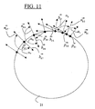
- FIG. 11:
- Explanation of the basic principle of data validation when performing the calibration
- FIG. 12:
- Representation of the permissible measuring speed as a function of the dynamic stiffness
- FIG. 13:
- Representation of the permissible measuring speed as a function of the stylus mass
Figur 1 zeigt rein beispielhaft ein Koordinatenmeßgerät vom sogenannten Portaltyp. Das Koordinatenmeßgerät umfaßt einen Meßtisch (1) auf dem ein zu vermessendes Werkstück (5) gelagert ist. Das Koordinatenmeßgerät weist eine Mechanik (3) in Form einer Portalmechanik auf, über die ein Tastkopf (9) in den drei Koordinatenrichtungen (x,y,z) verfahren werden kann. Das Portal (6) der Mechanik (3) ist hierbei in einer ersten mit (y) bezeichneten Richtung beweglich gelagert. An der horizontalen Traverse des Portals (6) wiederum ist ein Querschlitten (7) in der mit (x) bezeichneten Richtung verfahrbar gelagert, der wiederum die vertikale Pinole (8) in der mit (z) bezeichneten Richtung verschieblich lagert. Am unteren Ende der Pinole (8) ist ein messender Tastkopf (9) befestigt. In den drei Koordinatenrichtungen (x,y,z) sind an der Mechanik (3) Maßstäbe (10,11,12) befestigt, die über hier nicht näher gezeigte Abtastköpfe abgetastet werden, so daß die sogenannte Maschinenposition (xM,yM,zM), das heißt also die Position der Mechanik (3) und damit des Tastkopfes (9) in den drei Koordinatenrichtungen (x,y,z) erfaßt werden kann.FIG. 1 shows purely by way of example a coordinate measuring machine of the so-called portal type. The coordinate measuring machine comprises a measuring table (1) on which a workpiece (5) to be measured is mounted. The coordinate measuring machine has a mechanism (3) in the form of a portal mechanism, via which a probe (9) in the three coordinate directions (x, y, z) can be moved. The portal (6) of the mechanism (3) is in this case movably mounted in a first direction (y). On the horizontal traverse of the portal (6), in turn, a transverse slide (7) is movably mounted in the direction (x), which in turn displaceably supports the vertical sleeve (8) in the direction indicated by (z). At the lower end of the quill (8) a measuring probe (9) is attached. In the three coordinate directions (x, y, z), scales (10, 11, 12) are fastened to the mechanism (3) and are scanned by scanning heads which are not shown here, so that the so-called machine position (x M , y M , z M ), ie, the position of the mechanism (3) and thus of the probe (9) in the three coordinate directions (x, y, z) can be detected.
Der Tastkopf (9) wiederum weist eine in den drei Koordinatenrichtungen auslenkbare Tastkopfmechanik auf, über der Taststift (13) aus seiner Ruhelage in den Koordinatenrichtungen (x,y,z) gegenüber dem Tastkopf (9) ausgelenkt werden kann, wobei außerdem Meßeinrichtungen vorgesehen sind, über die die Taststiftauslenkung (xT,yT,zT), also die Auslenkung des Taststiftes (13) gegenüber dem Tastkopf (9) in den drei Koordinatenrichtungen (x,y,z) gemessen werden kann. Des weiteren können im Tastkopf (9) Meßkraftgeneratoren vorgesehen sein, über die auf den Taststift (13) in den Koordinatenrichtungen eine Meßkraft aufgeschaltet werden kannThe probe head (9), in turn, has a probe mechanism which can be deflected in the three coordinate directions, by means of which stylus (13) can be deflected from its rest position in the coordinate directions (x, y, z) relative to the probe head (9), measuring devices also being provided , via which the Taststiftauslenkung (x T , y T , z T ), so the deflection of the stylus (13) relative to the probe (9) in the three coordinate directions (x, y, z) can be measured. Furthermore, measuring force generators can be provided in the probe head (9) via which a measuring force can be applied to the feeler pin (13) in the coordinate directions
Die Mechanik (3) ist zusätzlich mit hier nicht näher zu sehenden Antrieben versehen, über die die Mechanik in den drei Koordinatenrichtungen verstellt werden kann.The mechanism (3) is additionally provided with not closer to here drives, about the mechanics can be adjusted in the three coordinate directions.
Um einen Meßablauf durchführen zu können, weist das Koordinatenmeßgerät ferner eine Steuer- und Auswerteeinheit (4) auf, die hier rein beispielhaft einen Rechner (26), sowie eine Steuerung (2) umfaßt. Zur Durchführung eines Meßablaufes werden vom Rechner (26) an die Steuerung (2) zur Durchführung des Meßablaufes wichtige Daten übergeben, wie beispielsweise die Sollform des zu vermessenden Werkstückes (5), der Mittelpunkt der Tastkugel des Taststiftes (13) im Maschinenkoordinatensystem oder die einzustellende Meßkraft, mit der der Taststift (13) gegen das Werkstück (5) gedrückt wird. Aus diesen Daten werden sogenannte Antriebssollwerte errechnet entsprechend denen dann die Mechanik (3) so verfahren wird, daß der Taststift (13) kontinuierlich über die Oberfläche des Werkstückes (5) geführt wird, beispielsweise um eine der beiden Bohrungen des Werkstückes (5) oder die obere Fläche des Werkstückes (5) zu vermessen oder um eine erfindungsgemäße Kalibrierung durchzuführen, wie sie weiter unten im Detail beschrieben wird. Die während des Meßablaufes von den Maßstäben (10,11,12) aufgenommenen Maschinenpositionen (xM,yM,zM) und die im Tastkopf (9) gemessenen Taststiftauslenkungen (xT,yT,zT) werden von der Steuerung (2) an den Rechner (26) weitergegeben. Im Rechner (26) werden dann die Maschinenpositionen (xM,yM,zM) und die Taststiftauslenkungen (xT,yT,zT) verrechnet und hieraus die Meßpunkte ermittelt und ausgewertet.In order to be able to carry out a measuring procedure, the coordinate measuring apparatus also has a control and evaluation unit (4), which here purely by way of example comprises a computer (26) and a controller (2). To carry out a measurement process important data are passed from the computer (26) to the controller (2) for carrying out the measurement process, such as the desired shape of the workpiece to be measured (5), the center of the probe ball of the stylus (13) in the machine coordinate system or to be set Measuring force with which the stylus (13) is pressed against the workpiece (5). From these data so-called drive setpoints are calculated according to which then the mechanism (3) is moved so that the stylus (13) is continuously guided over the surface of the workpiece (5), for example, one of the two holes of the workpiece (5) or upper surface of the workpiece (5) to measure or to perform a calibration according to the invention, as described in detail below. The machine positions (x M , y M , z M ) recorded during the measurement process by the scales (10, 11, 12) and the stylus deflections (x T , y T , z T ) measured in the probe (9) are detected by the controller (FIG. 2) to the computer (26) passed. In the computer (26) then the machine positions (x M , y M , z M ) and the Taststiftauslenkungen (x T , y T , z T ) are calculated and determined from the measurement points and evaluated.
Bei einer solchen kontinuierlichen Abtastung eines Werkstückes, die man auch als Scanning bezeichnet, treten bei gekrümmter abzutastender Bahn sowie auch bei sich verändernder Abtastgeschwindigkeit Beschleunigungen auf, die infolge der Massenträgheit der bewegten Teile und der nur begrenzten Steifigkeit der Bauelemente des Koordinatenmeßgerätes zu dynamischen Verformungen führen.In such a continuous scanning of a workpiece, which is also called scanning referred occur with curved scanned web as well as in changing Sampling speed accelerations due to the inertia of the moving Parts and the limited rigidity of the components of the coordinate to cause dynamic deformations.
Die drei unterschiedlichen Beschleunigungszustände, die beim Abtasten längs einer beliebigen Bahn auftreten können, werden nunmehr anhand der rein schematischen Darstellung gemäß Figur 2 erläutert.The three different acceleration states that occur when scanning along a Any path can now be on the basis of purely schematic Representation illustrated in Figure 2.
Zunächst einmal treten am Anfang (c) und am Ende (f) der abzutastenden Bahn (14) Anlaufund Brems- Beschleunigungen in Richtung der abzufahrenden Bahn (14) auf. In diesem Bereich sind die Antastbedingungen infolge des Regelverhaltens der Maschine durch große Tasterauslenkungen und Regelschwingungen sowie durch die Beschleunigung in Richtung der Bahn gekennzeichnet. Infolge fehlender Kraftaufschaltung in Bahnrichtung bleibt der Tastkopf bei Start und Stop im Beharrungszustand. First of all, at the beginning (c) and at the end (f) of the web (14) to be scanned, start-up and kick-off occur Braking accelerations in the direction of the trajectory (14). In this Area are the contact conditions due to the control behavior of the machine by large Pushbutton deflections and control vibrations as well as through the acceleration in the direction the railway marked. As a result of lack of force activation in the web direction remains the Probe at start and stop in steady state.
Des weiteren treten im Bereich (d) Beschleunigungen tangential zur Werkstückoberfläche auf, da die Bahn auf der ansonsten in diesem Bereich ebenen Werkstückoberfläche gekrümmt ist. Diese Beschleunigungen haben keine Normalkomponente in Bezug auf die Werkstückoberfläche.Furthermore, accelerations occur tangentially to the workpiece surface in region (d) on, since the web is curved on the otherwise planar workpiece surface in this area is. These accelerations have no normal component with respect to Workpiece surface.
Außerdem können auch Beschleunigungen normal zur Werkstückoberfläche auftreten, wenn die Werkstückoberfläche gekrümmt ist, wie dies beispielhaft der Bereich (e) der abzutastenden Bahn (14) zeigt.In addition, accelerations may occur normal to the workpiece surface, if the workpiece surface is curved, as exemplified by the region (e) of to be scanned web (14) shows.
Die betreffende Beschleunigung zeigt in den letzten beiden Fällen, d.h. bei gekrümmter Bahn
immer in Richtung zum Krümmungsmittelpunkt und liegt in der Schmiegebene. Diese
Beschleunigung hat den Betrag
Wobei (
Dieser Beschleunigungsvektor (
Es hat sich gezeigt, daß insbesondere auch die Verformung des Taststiftes (13) infolge der eben beschriebenen Beschleunigungen zu einer erheblichen Verfälschung der Meßergebnisse führt. Die bei entsprechenden Beschleunigungen auftretenden Verformungen des Taststiftes (13) hängen neben der Masse des Taststiftes (13) und seiner Steifigkeit auch unter anderem von seiner Masseverteilung ab, wie dies Figuren 3 und 4 verdeutlichen. Die Figuren 3 und 4 zeigen hierbei rein schematisch zwei Taststifte (13), die sowohl dieselbe statische Biegesteifigkeit, wie auch dieselbe Masse aufweisen. Lediglich das kegelstumpfförmige Bauteil (27) ist im Falle von Figur 3 mit seiner Grundfläche nach oben ausgerichtet, während es im Falle der Figur 4 nach unten ausgerichtet ist. Damit befindet sich der Massenschwerpunkt (spTaster) im Falle von Figur 3 höher als im Falle von Figur 4, sodaß sich die beiden Taststifte (13) bei gleichen Beschleunigungen vollkommen unterschiedlich verformen. Dies hat zur Folge, daß für jeden einzelnen Taststift, der bei Messungen auf dem Koordinatenmeßgerät benutzt wird eigene Korrekturdaten vorgesehen werden müssen, über die unter anderem die Verformung des Taststiftes korrigiert wird.It has been shown that, in particular, the deformation of the stylus (13) as a result of the accelerations just described leads to a significant falsification of the measurement results. The deformations of the stylus (13) which occur during corresponding accelerations depend not only on the mass of the stylus (13) and its rigidity, but also on its mass distribution, as illustrated by FIGS. 3 and 4. FIGS. 3 and 4 show, purely schematically, two feeler pins (13) which have both the same static bending stiffness and the same mass. Only the frusto-conical component (27) is aligned in the case of Figure 3 with its base upwards, while it is aligned in the case of Figure 4 downwards. Thus, the center of mass (SP button ) in the case of Figure 3 is higher than in the case of Figure 4, so that the two styli (13) deform completely different at the same accelerations. This has the consequence that for each individual stylus, which is used in measurements on the coordinate measuring machine own correction data must be provided, via which, inter alia, the deformation of the stylus is corrected.
Die sich hierbei bei einer gekrümmten Bahn ergebende Verformung soll nunmehr unter
Bezugnahme auf Figur 5 erfolgen, in der ein zur Erläuterung der Verformungsvorgänge etwas
allgemeiner Taststift (16) verwendet ist. Figur 5 zeigt die Verformung des Taststiftes (16),
wenn der Tastkopf (9) auf einer gekrümmten Bahn bewegt wird, beispielsweise auf einer
horizontal ausgerichteten Kreisbahn. Die Berechnung der Verschiebung (
- Die Pinole (8) mit dem Tastkopfgehäuse des Tastkopfes (9) unterliegt infolge von Trägheitskräften einer Parallelverschiebung, während die Neigung der Pinole vernachlässigbar ist; dieser Fehler wird in der Steuerung bereits korrigiert.
- Verformungswirksame Trägheitskräfte entstehen durch die beweglich im Tastkopf aufgehängten Tastkopfmassen, also beispielsweise Federparallelogramme, die den Taststift (16) gegenüber dem Tastkopf (9) beweglich lagern oder eine Taststiftwechselhalterung, die den Taststift (9) auswechselbar an der Tastkopfmechanik aufnimmt, sowie durch die verteilte Masse des Taststiftes (16). Es sei an dieser Stelle ausdrücklich darauf hingewiesen, daß der Begriff Taster in dieser Patentanmeldung immer sowohl den Taststift (16), wie auch die im Tastkopf (9) vorhandenenen mit dem Taststift (16) verbundenen Teile, die beweglich gegenüber dem Tastkopfgehäuse gelagert sind, umfassen.
- Die Verschiebung der beweglichen Teile des Tastkopfes (9) sowie die Verformung des
Taststiftes (16) bewirken den dynamischen Verformungsvektor (
w ges ), der als dynamische Tasterbiegung interpretiert wird.
- The sleeve (8) with the probe housing of the probe (9) is subject to a parallel displacement due to inertial forces, while the inclination of the sleeve is negligible; this error is already corrected in the controller.
- Deformation-effective inertial forces are produced by the probe head movably suspended in the probe head, that is to say spring parallelograms which movably support the feeler pin (16) relative to the probe head (9) or a feeler change holder which interchangeably receives the feeler pin (9) on the probe mechanism and by the distributed mass of the stylus (16). It should be emphasized at this point that the term probe in this patent application always both the stylus (16), as well as in the probe (9) existing with the stylus (16) connected parts which are movably mounted relative to the probe housing, include.
- The displacement of the movable parts of the probe (9) and the deformation of the stylus (16) cause the dynamic deformation vector (
w ges ), which is interpreted as dynamic probe bending.
Zur analytischen Beschreibung des Verformungsvektors (
Wie bereits oben ausgeführt, gibt es zwei dominierende Beschleunigungsrichtungen, nämlich
eine Beschleunigungsrichtung normal zur Werkstückoberfläche und eine tangential zur
Werkstückoberfläche. Es ist deshalb zweckmäßig, die Dynamikmatrix (D) wie folgt in die
symmetrische (Ds) und die antisymmetrische (Da) Komponente aufzuspalten. Die gesamte
Dynamikmatrix (D) ergibt sich als der Summe der Dynamikmatrizen zu D=Ds+Da


Bei der Beurteilung der Auswirkung der dynamischen Verformung ist zu beachten, daß der
Verformungsvektor (
Die symmetrische Ergänzungsmatrix (D s) beschreibt die wirksamen Fehler für den Fall, daß
die Beschleunigung (
Die antisymmetrische Ergänzungsmatrix (D a) beschreibt hingegen die dynamischen Fehler
für den Fall, daß die Beschleunigung (
Die Figuren 6 und 7 zeigen die beiden Grenzfälle beim Abtasten längs einer gleichen
Kreisbahn. Im Falle der Figur 6 wird die Kreisbahn auf einer Kugel (18) abgetastet. Im Falle
der Figur 7 wird dieselbe Kreisbahn entlang einer ebenen Fläche eines Werkstückes (19)
abgetastet. In beiden Fällen wirken sich dieselben Verformungskomponenten des gleichen
Verformungsvektors (
Umfangreiche Testmessungen haben ergeben, daß der Hauptanteil der dynamischen Verformung alleine durch eine Dynamikmatrix (DM) beschrieben werden kann, die die Verformung beschreibt, die sich aus der Masse des Taststiftes (16), sowie den Massen der beweglichen Teile des Tastkopfes (9) in den unterschiedlichen Richtungen ergibt.Extensive test measurements have shown that the majority of the dynamic deformation can be described solely by a dynamic matrix (D M ) which describes the deformation resulting from the mass of the stylus (16) and the masses of the moving parts of the probe (9). in different directions.
Die verbleibenden Restabweichungen können dann durch die symmetrische Ergänzungsmatrix (Ds) und die antisymmetrische Ergänzungsmatrix (Ds) beschrieben werden.The remaining discrepancies can then by the symmetrical supplement matrix (D s) and the anti-symmetric supplement matrix (D s) will be described.
Ausgehend von obigen Erläuterungen ergibt sich für den Verformungsvektor (
- N T
- statische Nachgiebigkeitsmatrix
- M T
- Massematrix der beweglichen Teile des Tastkopfes
- E
- Einheitsmatrix
- m
- Masse des Taststiftes
- A T
- Verformungsmatrix, die die Verformung des Taststiftes beschreibt, die sich aus der speziellen Verteilung der Taststiftmasse ergibt
- A M
- Matrix, die eventuelle Restfehler bei der Korrektur der dynamischen Verformung des Koordinatenmeßgerätes beschreibt
- D M
- Dynamikmatrix aus der Taststiftmasse und der Masse der beweglichen Teile des Tastkopfes
- D s
- symmetrische Ergänzungmatrix
- D a
- antisymmetrische Ergänzungsmatrix
- N T
- static compliance matrix
- M T
- Mass matrix of the moving parts of the probe
- e
- identity matrix
- m
- Mass of the stylus
- A T
- Deformation matrix which describes the deformation of the stylus resulting from the specific distribution of stylus mass
- A M
- Matrix that describes any residual errors in the correction of the dynamic deformation of the coordinate
- D M
- Dynamics matrix from the stylus mass and the mass of the moving parts of the probe
- D s
- symmetric complement matrix
- D a
- antisymmetric supplementary matrix
Dieses Ergebnis ist für die Realisierung der Korrektur der dynamischen Fehler des Koordinatenmeßgerätes ganz wesentlich und führt zu folgender Schlußfolgerung: This result is for the realization of the correction of the dynamic error of the Coordinate measuring machine and leads to the following conclusion:
Die Dynamikmatrix (DM) kann als Näherung (D0) der Dynamikmatrix (D) bei Kenntnis der Taststiftmasse (m) aus der bekannten Massenmatrix (MT) der beweglichen Teile des Tastkopfes und der statischen Nachgiebigkeitsmatrix (NT) unmittelbar berechnet werden. Diese Matrix beschreibt mit guter Näherung sowohl die symmetrischen als auch die antisymmetrischen Komponenten der Dynamikmatrix (D). Eine gesonderte Kalibrierung ist für diese Matrix (D 0) nicht erforderlich.The dynamic matrix (D M ) can be calculated as an approximation (D 0 ) of the dynamic matrix (D) with knowledge of the stylus mass ( m) from the known mass matrix (M T ) of the movable parts of the probe and the static compliance matrix (N T ). This matrix describes, with a good approximation, both the symmetric and antisymmetric components of the dynamics matrix (D). A separate calibration is not required for this matrix ( D 0 ).
Die symmetrische Ergänzungsmatrix (Ds) kann nach der Berechnung Dynamikmatrix (D0) durch eine Kalibrierung an einem rotationssymmetrischen Prüfkörper, wie beispielsweise einer Kugel bestimmt werden, wie dies weiter unten noch beschrieben wird. Die zur Kalibrierung der symmetrischen Ergänzungsmatrix (Ds) ermittelten Meßwerte werden bereits unter Verwendung der Dynamikmatrix (D0) korrigiert.The symmetrical supplementary matrix (D s ) can be determined by the calculation dynamic matrix (D 0 ) by a calibration on a rotationally symmetric test specimen, such as a ball, as will be described below. The measured values determined for calibration of the symmetrical supplementary matrix (D s ) are already corrected using the dynamic matrix (D 0 ).
Die antisymmetrische Ergänzungsmatrix (D a) wird dann kalibriert, indem ein Kalibrierkörper mit einer Ebene definierter räumlicher Orientierung abgetastet wird. Die zur Kalibrierung aufgenommenen Meßwerte werden ebenfalls bereits unter Verwendung der Dynamikmatrix (D0) und der symmetrischen Ergänzungsmatrix (Ds) korrigiert.The antisymmetric supplementary matrix ( D a ) is then calibrated by scanning a calibration body with a plane of defined spatial orientation. The measured values recorded for calibration are also already corrected using the dynamic matrix (D 0 ) and the symmetrical supplementary matrix (D s ).
Wie oben beschrieben berechnet sich die Dynamikmatrix (DM) wie folgt: D M = N T(M T + m E) .As described above, the dynamic matrix (D M ) is calculated as follows: D M = N T ( M T + m E ).
Hierbei repräsentiert (N T) die statische Nachgiebigkeitsmatrix, die die richtungsabhängige statische Steifigkeit des Taststiftes (16) und der beweglichen Teile des Tastkopfes (9) beschreibt. Diese Nachgibigkeitsmatrix kann beispielsweise durch die Finite Elemente Methode berechnet werden. Alternativ kann die Nachgibigkeitsmatrix über eine entsprechende Kalibrierung bestimmt werden, wie dies beispielsweise in der Veröffentlichung "Multidimensional measuring probe head improves accuracy and functionality of coordinate measuring machines" von Prof. W. Lotze, erschienen im Jahre 1994 in der Zeitschrift "Measurement" Nr. 13 (Elsevier Science) auf den Seiten 91 bis 97 oder im Artikel "High-Speed-Scanning auf Koordinatenmeßgeräten" von Prof. Werner Lotze, erschienen im Jahre 1993 in der Zeitschrift "Microtecnic" Nr. 4, beschrieben wurde.Here, ( N T ) represents the static compliance matrix describing the directional static stiffness of the stylus (16) and the moving parts of the probe (9). This compliance matrix can be calculated, for example, by the finite element method. Alternatively, the compliance matrix can be determined via a corresponding calibration, as described, for example, in the publication "Multidimensional measuring probe head accuracy and functionality of coordinate measuring machines" by Prof. W. Lotze, published in 1994 in the journal "Measurement" no. 13 (Elsevier Science) on pages 91 to 97 or in the article "High-speed scanning on coordinate measuring machines" by Prof. Werner Lotze, published in 1993 in the journal "Microtecnic" No. 4 described.
Der Parameter (M T) repräsentiert eine Massematrix, die die jeweiligen Massen der beweglichen Teile des Tastkopfes in den drei Koordinatenrichtungen (x,y,z) enthält. Die betreffenden Massen für die betreffenden Richtungen können rechnerisch bestimmt werden, indem die Massen der betreffenden einzelnen Bauteile gemessen werden und dann für jede der drei Koordinatenrichtungen (x,y,z) die Massen der in der betreffenden Richtung beweglichen Bauteile zusammengezählt werden. Alternativ können die Massen beispielsweise auch bestimmt werden, indem der Tastkopf ohne Taststift in eine Richtung beschleunigt wird und entsprechend über die im Tastkopf befindlichen Meßkraftgeneratoren eine Gegenkraft derart erzeugt wird, daß die beweglichen Teile im Tastkopf in ihrer Ruhelage bleiben. Aus der aufgeschalteten Meßkraft und der Beschleunigung kann über die Beziehung F=m*a die Masse des Tastkopfes in der betreffenden Richtung berechnet werden.The parameter ( M T ) represents a mass matrix containing the respective masses of the moving parts of the probe in the three coordinate directions (x, y, z). The relevant masses for the respective directions can be determined by calculating the masses of the individual components concerned and then, for each of the three coordinate directions (x, y, z), the masses of the components moving in the relevant direction are added together. Alternatively, the masses can also be determined, for example, by accelerating the probe without stylus in one direction and correspondingly generating a counter force on the measuring force generators located in the probe so that the moving parts in the probe remain in their rest position. From the applied measuring force and the acceleration, the mass of the probe in the relevant direction can be calculated via the relationship F = m * a.
Hinter der Bezeichnung (m) verbirgt sich schließlich die Masse des Taststiftes (16), die mit
der Einheitsmatrix

Das gewählte Grundprinzip für die Kalibrierung der symmetrischen Dynamikmatrix (Ds)
wird anhand von Figur 8 erläutert. Wird eine Kugel (18), wie sie beispielhaft in Figur 8
gezeigt ist, statisch oder quasistatisch gemessen, das heißt, daß die zum abtasten der Kugel
(18) verwendete Meßgeschwindigkeit (vl) sehr gering ist, dann liegen sämtliche Meßpunkte
auf der idealen Kugel. Eine Messung bei höherer Geschwindigkeit (vs) ergibt hingegen
Meßpunkte, denen die dynamische Verformung überlagert ist, so daß die Kugel dann als
Ellipsoid erscheint. Diese Abweichung muß nun an unterschiedlichen Stellen der Kugel (18)
als Funktion der Beschleunigung (
Damit die Rechnung numerisch stabil wird, muß die Kugel (18) auf der dem Taststift (16) zugänglichen Seite in einem hinreichend dichten Netz gemessen werden. Als hinreichend hat sich die Messung entlang dreier sich etwa senkrecht schneidender Großkreise (20,21,22) erwiesen, wobei ein Großkreis (21) vollständig und die anderen zwei Großkreise (20,22) jeweils mindestens über 180° zu messen sind. Die drei Großkreise (20,21,22) werden jeweils mit zwei unterschiedlichen Meßgeschwindigkeiten (vl, vs) gemessen.In order for the bill to be numerically stable, the ball (18) on the side accessible to the stylus (16) must be measured in a sufficiently dense network. The measurement has proved to be adequate along three large circles (20, 21, 22) which approximately intersect perpendicularly, with one large circle (21) being complete and the other two large circles (20, 22) each measuring at least 180 °. The three great circles (20, 21, 22) are each measured at two different measuring speeds (v 1 , v s ).
Für die Bestimmung der Koeffizienten der symmetrischen Dynamikmatrix (Ds) wird wie folgt vorgegangen:For the determination of the coefficients of the symmetric dynamics matrix (D s ), the procedure is as follows:
Aus den quasistatischen Messungen mit einer sehr geringen Meßgeschwindigkeit (vl) wird
der Mittelpunkt (
Bevor die bei der hohen Meßgeschwindigkeit (vs) aufgenommenen Meßpunkte (pki)
ausgewertet werden, sollte eine Datenvalidierung vorgenommen werden, die die Meßpunkte
als gültig oder als ungültig validiert. Um das Prinzip dieser Datenvalidierung zu erläutern
wird auf Figur 11 bezug genommen. Hierin sind die nacheinander auf dem Kreis
aufgenommenen Meßpunkte (
Um die Meßpunkte als gültig oder ungültig zu validieren wird deshalb der Winkel (αi)
zwischen den jeweiligen Normalenvektoren und den Beschleunigungsvektoren ausgewertet.
Wie bei den ersten beiden Meßpunkten (
Die eben beschriebene Datenvalidierung kann natürlich völlig analog auch mit den gemessenen Meßwerten bezüglich der auf das Werkstück aufgeschalteten Meßkraft durchgeführt werden. Hier ist der Winkel zwischen dem Meßkraftvektor und dem betreffenden Normalenvektor zu bilden. The just-described data validation can of course completely analogous with the Measured measured values with respect to the force applied to the workpiece measuring force be performed. Here is the angle between the Meßkraftvektor and the to form the relevant normal vector.
Die beschriebene Datenvalidierung sollte sowohl bei der Kalibrierung der Dynamiktensoren verwendet werden, wie auch im späteren Meßablauf.The data validation described should be used both in the calibration of the dynamics tensors be used, as in the later measurement.
Wie nunmehr aus den bei der hohen Geschwindigkeit gemessenen Meßpunkten die Parameter
der symmetrischen Ergänzungsmatrix (Ds) ermittelt werden, soll anhand von Figur 9 erläutert
werden. Für den senkrechten Abstand (aa) eines bei hoher Abtastgeschwindigkeit (vs)
gemessenen Meßpunktes (
Aus der Modellgleichung Gleichung 7 folgt andererseits für den senkrechten Abstand
(aa ≈ wn) eines Meßpunktes (
Die unbekannten Koeffizienten (dsij) der Matrix (Ds) in
Gleichung 9 werden durch Optimierung nach der Methode der kleinsten Quadrate bestimmt.

Die Lösung für den Parametervektor (d), der die Parameter der symmetrischen
Ergänzungsmatrix enthält

Wegen der Linearität der Gleichung 10 ist die direkte Berechnung des Parameter-vektors (
Die Berechnung der drei Koeffizienten der antisymmetrischen Matrix (Da) verläuft - ausgehend von dem theoretischen Modell - im wesentlichen nach dem gleichen Schema mit einem Kalibrierwürfel (23) mit ebenen Kalibrierflächen, die parallel zu den Koordinatenebenen, das heißt also zur x-y-Ebene, zur x-z-Ebene und zur y-z-Ebene ausgerichtet sind. Die Auswertung umfangreicher Testmessungen hat hierbei ergeben, daß die vollständige dynamische Korrektur für die Messung von ebenen Flächen in beliebiger räumlicher Orientierung nicht möglich ist. Sie ist aber andererseits in dieser Allgemeinheit auch nicht notwendig, da für die Messung ebener Werkstückflächen jeweils ein Taster bestimmter Konfiguration eingesetzt wird. Die Korrektur und folglich auch die dynamische Kalibrierung ist dann für die aktuelle räumliche Orientierung ausreichend. Diese Einschränkung ist gleichbedeutend mit der Kalibrierung von nur zwei antisymmetrischen Koeffizienten von (Da) an einer ebenen Fläche mit der jeweiligen räumlichen Orientierung.The calculation of the three coefficients of the antisymmetric matrix (D a ) proceeds - based on the theoretical model - essentially according to the same scheme with a calibration cube (23) with flat calibration surfaces which are parallel to the coordinate planes, that is to the xy plane, aligned to the xz plane and the yz plane. The evaluation of extensive test measurements has shown that the full dynamic correction for the measurement of flat surfaces in any spatial orientation is not possible. However, on the other hand, it is not necessary in this generality since a probe of a certain configuration is used for the measurement of planar workpiece surfaces. The correction and consequently the dynamic calibration is then sufficient for the current spatial orientation. This restriction is equivalent to the calibration of only two antisymmetric coefficients of (D a ) on a flat surface with the respective spatial orientation.
Die Meßanordnung sowie den Modellansatz für die Kalibrierung zeigt Figur 10. Hierbei wird
zunächst die Ebene (25) eines Würfels (23) längs einer Kreisbahn (24) quasistatisch
gemessen, d.h. mit einer sehr geringen Meßgeschwindigkeit (vl). Der Durchmesser der
Kreisbahn (24) entspricht hierbei in etwa dem Durchmesser der Kalibrierkugel (18). Aus den
Meßwerten wird ein Ausgleichskreis mit dem Mittelpunkt (
Zur Berechnung der Matrix (Da) führt man zweckmäßig ein lokales Koordinatensystem mit
den Koordinatenrichtungen (x*,y*,z*) mit der Flächennormale (
Für den Abstand (aa = wn) eines Meßpunktes (
Der Abstand (aa) ist, wie oben bereits ausgeführt, die z-Komponente des
Verschiebungsvektors (
Das Normalgleichungssystem für die beiden Koeffizienten folgt dann zu


Die erhaltene antisymmetrische Dynamikmatrix (D*a) ist anschließend mit der Gleichung 18 in das Meßkoordinatensystem (x,y,z) zu transformieren. Die resultierende Dynamikmatrix (D) ergibt sich dann durch Addition der drei Anteile (D0, Ds und Da) nach Gleichung 7.The obtained antisymmetric dynamic matrix (D * a ) is then to be transformed by equation 18 into the measuring coordinate system (x, y, z). The resulting dynamic matrix (D) is then obtained by adding the three components (D 0 , D s and D a ) according to Equation 7.
Wenn eine vollständige Korrektur aller dynamischen Verformungen korrigiert werden soll, muß die Tasterkalibrierung der Reihenfolge nach in den folgenden drei Stufen für die statische und dynamische Kalibrierung des statischen Biegetensors (N) und des Dynamiktensors (D) durchgeführt werden:
- Statische Tasterkalibrierung an der Kalibrierkugel (Tasterdurchmesser, Tasteroffset,
Biegetensor) sowie Berechnung der Näherung D 0 des Dynamiktensors.
Aktueller Dynamiktensor ist nach erfolgreicher Kalibrierung D = D 0. - Ermitteln der symmetrischen Ergänzungsmatrix (Ds) Dynamiktensors für die Korrektur von dynamischen Fehlern bei der Messung von Bohrungen, Wellen, Kugeln u. ä. Der aktuelle Dynamiktensor (D) ist nach erfolgreicher Kalibrierung D = D0 + Ds
- Ermitteln der antisymmetrischen Ergänzungsmatrix (Da) des Dynamiktensors für die Korrektur von dynamischen Fehlern bei der Messung von Ebenen mit etwa gleicher Raumorientierung, stumpfen Kegeln usw.. Der aktuelle Dynamiktensor (D) ist nach erfolgreicher Kalibrierung D = D 0 + D s + D a.
- Static probe calibration on the calibration sphere (probe diameter, probe offset, bending sensor) and calculation of the approximation D 0 of the dynamic tensor.
Current Dynamics Tensor is D = D 0 after successful calibration. - Determining the symmetric supplementary matrix (D s ) Dynamics tensors for the correction of dynamic errors in the measurement of holes, waves, spheres u. ä. The current dynamics tensor (D) is after successful calibration D = D 0 + D s
- Determining the antisymmetric supplementary matrix (D a ) of the dynamic tensor for the correction of dynamic errors in the measurement of planes with approximately the same spatial orientation, blunt cones, etc. The current dynamics tensor (D) is after successful calibration D = D 0 + D s + D a .
Die einzelnen Kalibrierschritte müssen in dieser Reihenfolge durchgeführt werden und nach jedem Schritt muß die zuletzt bestimmte Ergänzungsmatrix (Ds, Da) zum bisher bestimmten Dynamiktensor (D) dazusummiert werden.The individual calibration steps must be carried out in this order and after For each step, the most recently determined supplementary matrix (Ds, Da) must be determined to date Dynamics Tensor (D) can be added.
Die Kalibrierung kann aber auch nach der ersten oder zweiten Stufe abgebrochen werden, wobei dann Restfehler bestehen bleiben. Für den Anwender besteht damit die Möglichkeit, in Abhängigkeit von der Meßaufgabe die Tasterkalibrierung auszuwählen. Bei einer Meßaufgabe beispielsweise, bei der nahezu keine tangentiale Abweichung zu erwarten ist, z.B. beim Messen einer Bohrung, kann auf die antisymmetrische Drehmatrix (Da) verzichtet werden.However, the calibration can also be aborted after the first or second stage, in which case residual errors remain. This allows the user to select the probe calibration depending on the measurement task. For example, in a measurement task in which almost no tangential deviation is to be expected, for example when measuring a bore, the antisymmetric torque matrix (D a ) can be dispensed with.
Natürlich kann selektiv auch nur eine beliebige Dynamikmatrix verwendet werden. Beispielsweise könnte nur die symmetrische Ergänzungsmatrix (Ds) kalibriert werden. Nachteilig hieran ist jedoch, daß sich insbesondere in Abhängigkeit von der jeweiligen Meßaufgabe größere Meßfehler ergeben können.Of course, selectively, only an arbitrary dynamics matrix can be used. For example, only the symmetric supplementary matrix (D s ) could be calibrated. The disadvantage of this, however, is that in particular depending on the particular measurement task can result in larger measurement errors.
Des weiteren sollte im Koordinatenmeßgerät die zulässige Meßgeschwindigkeit in Abhängigkeit von der dynamischen Steifigkeit, die im kalibrierten Dynamiktensor hinterlegt ist verändert werden. Wie aus Figur 12 zu sehen ist, kann die maximal zulässige Meßgeschwindigkeit (vmax) bis zu einer dynamischen Steifigkeit (Cgrenz) zugelassen werden. Danach wird die zulässige Meßgeschwindigkeit bei kleiner werdender Steifigkeit in einem Übergangsbereich bis auf (vmin) reduziert. Bei Steifigkeiten kleiner als (Cmin) wird entweder der Meßablauf gar nicht mehr ausgeführt oder aber an den Anwender eine entsprechende Meldung ausgegeben.Furthermore, in the coordinate measuring machine, the permissible measuring speed should be changed as a function of the dynamic stiffness which is stored in the calibrated dynamic tensor. As can be seen from FIG. 12, the maximum permissible measuring speed (v max ) can be permitted up to a dynamic rigidity (C limit). Thereafter, the allowable measurement speed is reduced with decreasing stiffness in a transition region to (v min ). For stiffnesses smaller than (Cmin), either the measuring procedure is no longer executed or a corresponding message is output to the user.
Des weiteren sollte außerdem in Abhängigkeit von der Masse des Taststiftes (13 bzw. 16) die Meßgeschwindigkeit verändert werden. Wie aus Figur 13 zu sehen ist, kann die maximal zulässige Meßgeschwindigkeit (vmax) bis zu einer Taststiftmasse (mgrenz) zugelassen werden. Danach wird die zulässige Meßgeschwindigkeit bei größer werdender Taststiftmasse in einem Übergangsbereich bis auf (vmin) reduziert. Bei Taststiftmassen größer als (mmax) wird entweder der Meßablauf gar nicht mehr ausgeführt oder aber an den Anwender eine entsprechende Meldung ausgegeben.Furthermore, the measuring speed should also be changed depending on the mass of the stylus (13 or 16). As can be seen from FIG. 13, the maximum permissible measuring speed (v max ) can be permitted up to a stylus mass (m limit ). Thereafter, the permissible measuring speed is reduced with increasing stylus mass in a transition region to (v min ). For stylus masses greater than (m max ), either the measuring procedure is no longer executed or a corresponding message is output to the user.
Die Reduzierung der zulässigen Meßgeschwindigkeiten erfolgt sowohl in Abhängigkeit von der Steifigkeit, wie auch in Abhängigkeit von der Taststiftmasse. Wird also die zulässige Meßgeschwindigkeit reduziert, weil die Steifigkeit den Wert (Cgrenz) unterschreitet, so wird diese bereits reduzierte Meßgeschwindigkeit nochmals weiter reduziert, wenn zusätzlich auch die Taststiftmasse den Wert (mgrenz) überschreitet.The reduction of the permissible measuring speeds takes place both as a function of the rigidity and in dependence on the stylus mass. If, therefore, the permissible measuring speed is reduced because the rigidity falls below the value (C limit), then this already reduced measuring speed is reduced even further if, in addition, the stylus mass also exceeds the value (m limit ).
Claims (13)
das Parameterfeld die Abweichungen bei Beschleunigung des Tasters normal zur Werkstückoberfläche beschreibt.Method for correcting the measurement results of a coordinate measuring machine, in which a workpiece is scanned continuously, with the following method steps:
the parameter field describes the deviations in acceleration of the probe normal to the workpiece surface.
das Paramterfeld die Abweichungen bei Beschleunigung des Tasters normal zur Werkstückoberfläche beschreibt.Coordinate measuring device comprising
the parameter field describes the deviations in acceleration of the probe normal to the workpiece surface.
Applications Claiming Priority (3)
| Application Number | Priority Date | Filing Date | Title |
|---|---|---|---|
| DE10025479 | 2000-05-23 | ||
| DE10025479 | 2000-05-23 | ||
| EP01112215A EP1158269B1 (en) | 2000-05-23 | 2001-05-18 | Correction method for coordinate measuring machines |
Related Parent Applications (1)
| Application Number | Title | Priority Date | Filing Date |
|---|---|---|---|
| EP01112215A Division EP1158269B1 (en) | 2000-05-23 | 2001-05-18 | Correction method for coordinate measuring machines |
Publications (2)
| Publication Number | Publication Date |
|---|---|
| EP1498691A1 true EP1498691A1 (en) | 2005-01-19 |
| EP1498691B1 EP1498691B1 (en) | 2009-08-12 |
Family
ID=7643230
Family Applications (2)
| Application Number | Title | Priority Date | Filing Date |
|---|---|---|---|
| EP04023526A Expired - Lifetime EP1498691B1 (en) | 2000-05-23 | 2001-05-18 | Correction method for coordinate measuring machines |
| EP01112215A Expired - Lifetime EP1158269B1 (en) | 2000-05-23 | 2001-05-18 | Correction method for coordinate measuring machines |
Family Applications After (1)
| Application Number | Title | Priority Date | Filing Date |
|---|---|---|---|
| EP01112215A Expired - Lifetime EP1158269B1 (en) | 2000-05-23 | 2001-05-18 | Correction method for coordinate measuring machines |
Country Status (4)
| Country | Link |
|---|---|
| US (1) | US6591208B2 (en) |
| EP (2) | EP1498691B1 (en) |
| JP (1) | JP5022544B2 (en) |
| DE (3) | DE50106760D1 (en) |
Cited By (3)
| Publication number | Priority date | Publication date | Assignee | Title |
|---|---|---|---|---|
| WO2007122362A1 (en) * | 2006-04-21 | 2007-11-01 | Renishaw Plc | Method of error correction |
| WO2013007285A1 (en) * | 2011-07-08 | 2013-01-17 | Carl Zeiss Industrielle Messtechnik Gmbh | Correcting and/or preventing errors during the measurement of coordinates of a workpiece |
| DE102013216093A1 (en) * | 2013-08-14 | 2015-02-19 | Carl Zeiss Industrielle Messtechnik Gmbh | Reduction of errors of a rotating device, in particular for the determination of coordinates of a workpiece or the machining of a workpiece |
Families Citing this family (37)
| Publication number | Priority date | Publication date | Assignee | Title |
|---|---|---|---|---|
| GB0126232D0 (en) * | 2001-11-01 | 2002-01-02 | Renishaw Plc | Calibration of an analogue probe |
| DE10214489A1 (en) * | 2002-03-26 | 2003-10-23 | Zeiss Carl | Guidance error determination method, for use with metrology or coordinate measurement instruments, whereby guidance errors are related to a particular factor and determined as a function of the factor using finite element analysis |
| DE10229821B4 (en) * | 2002-06-28 | 2004-11-11 | Carl Zeiss | Coordinate measuring device and method for controlling a coordinate measuring device with variable probe mass |
| DE10237501A1 (en) * | 2002-08-16 | 2004-03-04 | Carl Zeiss | Coordinate measuring machine and correction method therefor |
| GB0326532D0 (en) * | 2003-11-13 | 2003-12-17 | Renishaw Plc | Method of error compensation |
| DE10360789B4 (en) * | 2003-12-23 | 2007-03-15 | Leuze Lumiflex Gmbh + Co. Kg | Device for monitoring a detection area on a work equipment |
| DE102004020996A1 (en) | 2004-04-19 | 2005-11-03 | Carl Zeiss Industrielle Messtechnik Gmbh | Coordinate measuring device for the metrological determination of a coordinate on a measured object |
| DE102004038416B4 (en) * | 2004-07-30 | 2014-02-06 | Carl Zeiss Industrielle Messtechnik Gmbh | Method for determining spatial coordinates of a measuring point on a measuring object and corresponding coordinate measuring machine |
| GB0417536D0 (en) * | 2004-08-06 | 2004-09-08 | Renishaw Plc | The use of surface measurement probes |
| GB0508273D0 (en) * | 2005-04-25 | 2005-06-01 | Renishaw Plc | Method for scanning the surface of a workpiece |
| DE102005032749A1 (en) | 2005-07-13 | 2007-01-18 | Carl Zeiss Industrielle Messtechnik Gmbh | Method for probing a workpiece with a coordinate measuring machine and coordinate measuring machines |
| GB0605796D0 (en) | 2006-03-23 | 2006-05-03 | Renishaw Plc | Apparatus and method of measuring workpieces |
| JP5221004B2 (en) * | 2006-05-25 | 2013-06-26 | 株式会社ミツトヨ | Measuring device, surface texture measuring method, and surface texture measuring program |
| JP5189806B2 (en) * | 2006-09-07 | 2013-04-24 | 株式会社ミツトヨ | Surface shape measuring device |
| FR2910136B1 (en) * | 2006-12-18 | 2009-02-27 | Essilor Int | METHOD FOR CORRECTING THE GEOMETRY OF A SPINNING LAYER APPROACHING A LONGITUDINAL STRAND OF A GOGGLE MOUNT DRAWER AND METHOD OF ACQUIRING THE GEOMETRY OF A CONTOUR OF SUCH A DRAWER |
| WO2009001385A1 (en) * | 2007-06-28 | 2008-12-31 | Hexagon Metrology S.P.A. | Method for determining dynamic errors in a measuring machine |
| EP2171394B2 (en) * | 2007-07-24 | 2020-07-15 | Hexagon Metrology S.p.A. | Method for compensating measurement errors caused by deformations of a measuring machine bed under the load of a workpiece and measuring machine operating according to said method |
| JP5192196B2 (en) * | 2007-08-03 | 2013-05-08 | 株式会社ミツトヨ | Surface shape measuring device |
| US7712224B2 (en) * | 2007-10-03 | 2010-05-11 | Hexagon Metrology Ab | Validating the error map of CMM using calibrated probe |
| DE102007051054A1 (en) | 2007-10-19 | 2009-04-30 | Carl Zeiss Industrielle Messtechnik Gmbh | Method for correcting the measured values of a coordinate measuring machine and coordinate measuring machine |
| DE102007057093A1 (en) * | 2007-11-20 | 2009-05-28 | Carl Zeiss Industrielle Messtechnik Gmbh | Method for calibrating a coordinate measuring machine |
| DE102008024444B4 (en) | 2008-05-14 | 2020-07-09 | Carl Zeiss Industrielle Messtechnik Gmbh | Method and device for calibrating a coordinate measuring machine |
| JP5612386B2 (en) * | 2010-07-23 | 2014-10-22 | 株式会社ミツトヨ | Shape measuring device |
| US9995574B2 (en) | 2011-08-11 | 2018-06-12 | Mitutoyo Corporation | CMM moving path adjustment assisting method and apparatus |
| CN104105944B (en) * | 2012-03-02 | 2016-11-09 | 海克斯康测量技术有限公司 | There is the coordinate measuring machine of the support beam of band spring |
| DE102013101931B4 (en) | 2013-02-27 | 2022-02-03 | Carl Zeiss Industrielle Messtechnik Gmbh | Method and device for measuring a workpiece |
| GB201311600D0 (en) * | 2013-06-28 | 2013-08-14 | Renishaw Plc | Calibration of a contact probe |
| JP6285146B2 (en) * | 2013-10-29 | 2018-02-28 | 株式会社ミツトヨ | Arm-type CMM and tilt correction method for base supporting arm-type CMM |
| JP6254456B2 (en) * | 2014-02-21 | 2017-12-27 | 株式会社ミツトヨ | CMM and correction matrix calculation method using CMM |
| EP3034991B2 (en) * | 2014-12-19 | 2022-08-24 | Hexagon Technology Center GmbH | Method and system for actively counteracting displacement forces with a probing unit |
| US9952044B2 (en) * | 2015-02-02 | 2018-04-24 | Rolls-Royce North American Technologies, Inc. | Multi-axis calibration block |
| DE102015109612B4 (en) | 2015-06-16 | 2020-08-13 | Carl Zeiss Industrielle Messtechnik Gmbh | Coordinate measuring machine and method for calibrating the same with a time-of-flight camera |
| DE102015116850A1 (en) | 2015-10-05 | 2017-04-06 | Carl Zeiss Industrielle Messtechnik Gmbh | Monitoring a safety-related parameter of a coordinate measuring machine |
| DE102019122654A1 (en) | 2019-08-22 | 2021-02-25 | M & H Inprocess Messtechnik Gmbh | Device for calibrating a speed of a movement axis of a machine |
| DE102019220060A1 (en) * | 2019-12-18 | 2021-06-24 | Carl Zeiss Industrielle Messtechnik Gmbh | Method for calibrating a tactile sensor |
| DE102020204313A1 (en) | 2020-04-02 | 2021-10-07 | Carl Zeiss Industrielle Messtechnik Gmbh | Procedure for calibrating a rotary switch |
| DE102020207756A1 (en) | 2020-06-23 | 2020-08-06 | Carl Zeiss Industrielle Messtechnik Gmbh | Method and device for determining a rigidity of a coordinate measuring device and coordinate measuring device specific to the measuring device |
Citations (5)
| Publication number | Priority date | Publication date | Assignee | Title |
|---|---|---|---|---|
| US4333238A (en) | 1979-03-30 | 1982-06-08 | Mcmurtry David R | Coordinate measuring machine |
| US5007006A (en) * | 1987-03-06 | 1991-04-09 | Renishaw Plc | Method of and apparatus for calibration of machines |
| CH681913A5 (en) * | 1991-02-13 | 1993-06-15 | Roland Juillerat | Position error checking system for head on numerically controlled machine - includes rotary device with angular and radial sensors measuring displacement of head as it performs circular movement about axis |
| EP0684448A2 (en) | 1994-05-27 | 1995-11-29 | Carl Zeiss | Procedure for coordinate measuring on workpieces |
| US5610846A (en) * | 1994-05-27 | 1997-03-11 | Carl Zeiss Stiftung | Method for coordinate measurement on workpieces adjusted for bending of measuring apparatus structure |
Family Cites Families (11)
| Publication number | Priority date | Publication date | Assignee | Title |
|---|---|---|---|---|
| US4819195A (en) * | 1987-01-20 | 1989-04-04 | The Warner & Swasey Company | Method for calibrating a coordinate measuring machine and the like and system therefor |
| US4796195A (en) * | 1987-05-13 | 1989-01-03 | Cincinnati Milacron Inc. | Method for machining with improved accuracy |
| US5152072A (en) * | 1988-02-18 | 1992-10-06 | Renishaw Plc | Surface-sensing device |
| US5189806A (en) * | 1988-12-19 | 1993-03-02 | Renishaw Plc | Method of and apparatus for scanning the surface of a workpiece |
| DE4001433A1 (en) * | 1990-01-19 | 1991-07-25 | Zeiss Carl Fa | CORRECTION PROCEDURE FOR COORDINATE MEASURING DEVICES |
| DE4245012B4 (en) * | 1992-04-14 | 2004-09-23 | Carl Zeiss | Method for measuring shaped elements on a coordinate measuring machine |
| JP3196145B2 (en) * | 1992-04-30 | 2001-08-06 | 日本電信電話株式会社 | Contact point and contact normal detection method for machining / assembly equipment |
| DE4436507A1 (en) * | 1994-10-13 | 1996-04-18 | Zeiss Carl Fa | Coordinate measurement of workpiece using coordinate measuring unit |
| US5832416A (en) * | 1995-09-01 | 1998-11-03 | Brown & Sharpe Manufacturing Company | Calibration system for coordinate measuring machine |
| DE59711571D1 (en) * | 1996-12-21 | 2004-06-03 | Zeiss Carl | Method for controlling coordinate measuring machines and coordinate measuring machine |
| DE19900724A1 (en) * | 1999-01-12 | 2000-07-27 | Zeiss Carl Fa | Coordinate measuring device |
-
2001
- 2001-05-18 DE DE50106760T patent/DE50106760D1/en not_active Expired - Lifetime
- 2001-05-18 EP EP04023526A patent/EP1498691B1/en not_active Expired - Lifetime
- 2001-05-18 DE DE50115041T patent/DE50115041D1/en not_active Expired - Lifetime
- 2001-05-18 EP EP01112215A patent/EP1158269B1/en not_active Expired - Lifetime
- 2001-05-19 DE DE10124493A patent/DE10124493A1/en not_active Ceased
- 2001-05-23 JP JP2001154588A patent/JP5022544B2/en not_active Expired - Fee Related
- 2001-05-23 US US09/862,321 patent/US6591208B2/en not_active Expired - Lifetime
Patent Citations (5)
| Publication number | Priority date | Publication date | Assignee | Title |
|---|---|---|---|---|
| US4333238A (en) | 1979-03-30 | 1982-06-08 | Mcmurtry David R | Coordinate measuring machine |
| US5007006A (en) * | 1987-03-06 | 1991-04-09 | Renishaw Plc | Method of and apparatus for calibration of machines |
| CH681913A5 (en) * | 1991-02-13 | 1993-06-15 | Roland Juillerat | Position error checking system for head on numerically controlled machine - includes rotary device with angular and radial sensors measuring displacement of head as it performs circular movement about axis |
| EP0684448A2 (en) | 1994-05-27 | 1995-11-29 | Carl Zeiss | Procedure for coordinate measuring on workpieces |
| US5610846A (en) * | 1994-05-27 | 1997-03-11 | Carl Zeiss Stiftung | Method for coordinate measurement on workpieces adjusted for bending of measuring apparatus structure |
Non-Patent Citations (1)
| Title |
|---|
| Q ET AL: "Error compensation of touch trigger probes", MEASUREMENT, INSTITUTE OF MEASUREMENT AND CONTROL. LONDON, GB, vol. 18, no. 1, 1 May 1996 (1996-05-01), pages 47 - 57, XP004040458, ISSN: 0263-2241 * |
Cited By (11)
| Publication number | Priority date | Publication date | Assignee | Title |
|---|---|---|---|---|
| WO2007122362A1 (en) * | 2006-04-21 | 2007-11-01 | Renishaw Plc | Method of error correction |
| CN101427100B (en) * | 2006-04-21 | 2012-05-30 | 瑞尼斯豪公司 | Method of error correction |
| WO2013007285A1 (en) * | 2011-07-08 | 2013-01-17 | Carl Zeiss Industrielle Messtechnik Gmbh | Correcting and/or preventing errors during the measurement of coordinates of a workpiece |
| CN103782130A (en) * | 2011-07-08 | 2014-05-07 | 卡尔蔡司工业测量技术有限公司 | Correcting and/or preventing errors during the measurement of coordinates of a workpiece |
| US20140167745A1 (en) * | 2011-07-08 | 2014-06-19 | Carl Zeiss Industrielle Messtechnik Gmbh | Correcting and/or preventing errors during the measurement of coordinates of a workpiece |
| US9671257B2 (en) | 2011-07-08 | 2017-06-06 | Carl Zeiss Industrielle Messtechnik Gmbh | Correcting and/or preventing errors during the measurement of coordinates of a workpiece |
| CN103782130B (en) * | 2011-07-08 | 2017-06-20 | 卡尔蔡司工业测量技术有限公司 | Measure workpiece coordinate when error correction and/or avoid |
| US10429178B2 (en) * | 2011-07-08 | 2019-10-01 | Carl Zeiss Industrielle Messtechnik Gmbh | Correcting and/or preventing errors during the measurement of coordinates of a work piece |
| DE102013216093A1 (en) * | 2013-08-14 | 2015-02-19 | Carl Zeiss Industrielle Messtechnik Gmbh | Reduction of errors of a rotating device, in particular for the determination of coordinates of a workpiece or the machining of a workpiece |
| DE102013216093B4 (en) * | 2013-08-14 | 2016-06-02 | Carl Zeiss Industrielle Messtechnik Gmbh | Reduction of errors of a rotating device, in particular for the determination of coordinates of a workpiece or the machining of a workpiece |
| US10073435B2 (en) | 2013-08-14 | 2018-09-11 | Carl Zeiss Industrielle Messtechnik Gmbh | Reducing errors of a rotatory device, in particular for the determination of coordinates of a workpiece or the machining of a workpiece |
Also Published As
| Publication number | Publication date |
|---|---|
| EP1158269A2 (en) | 2001-11-28 |
| JP2002022435A (en) | 2002-01-23 |
| DE50106760D1 (en) | 2005-08-25 |
| EP1158269B1 (en) | 2005-07-20 |
| JP5022544B2 (en) | 2012-09-12 |
| US20020029119A1 (en) | 2002-03-07 |
| DE10124493A1 (en) | 2001-11-29 |
| EP1498691B1 (en) | 2009-08-12 |
| DE50115041D1 (en) | 2009-09-24 |
| US6591208B2 (en) | 2003-07-08 |
| EP1158269A3 (en) | 2002-06-26 |
Similar Documents
| Publication | Publication Date | Title |
|---|---|---|
| EP1158269B1 (en) | Correction method for coordinate measuring machines | |
| EP2201328B1 (en) | Method for correcting the measured values of a coordinate measurement device, and coordinate measurement device | |
| EP0684447B1 (en) | Coordinate measurement on workpieces with a correction of the bending behaviour of the coordinate measuring machine dependent on the measuring force | |
| EP2834595B1 (en) | Method and apparatus for reducing errors of a rotating device when determining coordinates of a workpiece or when machining a workpiece | |
| DE602005005839T2 (en) | USE OF SURFACE TESTS | |
| DE60019219T2 (en) | METHOD FOR CALIBRATING A SCAN SYSTEM | |
| EP2331907B1 (en) | Method for measuring a work piece and coordinate measuring device | |
| DE60018412T2 (en) | CONTROL UNIT FOR MEASURING INSTRUMENT | |
| EP2212647A1 (en) | Method for calibrating a coordinate measuring device | |
| DE4436507A1 (en) | Coordinate measurement of workpiece using coordinate measuring unit | |
| DE102020206719A1 (en) | Position measuring method and position measuring system for an object in a machine tool | |
| EP0769677A2 (en) | Procedure for the coordinate measurement on objects | |
| EP1627203B1 (en) | Method for calibrating a probe | |
| DE19809589B4 (en) | Method for calibrating a probe of a coordinate measuring machine | |
| DE3781674T2 (en) | POSITION DETERMINATION METHOD WITHIN THE MEASURING SPACE OF A COORDINATE MEASURING DEVICE AND THE LIKE AND SYSTEM THEREFOR. | |
| DE10237501A1 (en) | Coordinate measuring machine and correction method therefor | |
| DE60032635T2 (en) | METHOD AND DEVICE FOR TESTING TOOLING MACHINES | |
| DE102008063236B4 (en) | Method for calibrating a measuring force on a coordinate measuring machine | |
| EP2124116B1 (en) | Method for controlling a CNC-controlled coordinate measuring device and coordinate measuring device | |
| DE102020208567B4 (en) | Calibration of a reference body for determining the guidance error of a machine axis | |
| EP0613573B1 (en) | Process for testing the working accuracy of an nc machine | |
| DE102020212982A1 (en) | Method for reducing measurement errors in a coordinate measuring machine and coordinate measuring machine | |
| DE102020204313A1 (en) | Procedure for calibrating a rotary switch | |
| DE10136559B4 (en) | Method for diagnosing damage in a measuring probe of a coordinate measuring machine | |
| DE102016226087B4 (en) | Rotating and swiveling sensor system for a coordinate measuring machine |
Legal Events
| Date | Code | Title | Description |
|---|---|---|---|
| PUAI | Public reference made under article 153(3) epc to a published international application that has entered the european phase |
Free format text: ORIGINAL CODE: 0009012 |
|
| 17P | Request for examination filed |
Effective date: 20041002 |
|
| AC | Divisional application: reference to earlier application |
Ref document number: 1158269 Country of ref document: EP Kind code of ref document: P |
|
| AK | Designated contracting states |
Kind code of ref document: A1 Designated state(s): DE FR GB IT |
|
| AKX | Designation fees paid |
Designated state(s): DE FR GB IT |
|
| 17Q | First examination report despatched |
Effective date: 20080724 |
|
| GRAP | Despatch of communication of intention to grant a patent |
Free format text: ORIGINAL CODE: EPIDOSNIGR1 |
|
| GRAS | Grant fee paid |
Free format text: ORIGINAL CODE: EPIDOSNIGR3 |
|
| GRAA | (expected) grant |
Free format text: ORIGINAL CODE: 0009210 |
|
| AC | Divisional application: reference to earlier application |
Ref document number: 1158269 Country of ref document: EP Kind code of ref document: P |
|
| AK | Designated contracting states |
Kind code of ref document: B1 Designated state(s): DE FR GB IT |
|
| REG | Reference to a national code |
Ref country code: GB Ref legal event code: FG4D Free format text: NOT ENGLISH |
|
| REF | Corresponds to: |
Ref document number: 50115041 Country of ref document: DE Date of ref document: 20090924 Kind code of ref document: P |
|
| PLBE | No opposition filed within time limit |
Free format text: ORIGINAL CODE: 0009261 |
|
| STAA | Information on the status of an ep patent application or granted ep patent |
Free format text: STATUS: NO OPPOSITION FILED WITHIN TIME LIMIT |
|
| 26N | No opposition filed |
Effective date: 20100517 |
|
| PGFP | Annual fee paid to national office [announced via postgrant information from national office to epo] |
Ref country code: FR Payment date: 20130603 Year of fee payment: 13 |
|
| REG | Reference to a national code |
Ref country code: FR Ref legal event code: ST Effective date: 20150130 |
|
| PG25 | Lapsed in a contracting state [announced via postgrant information from national office to epo] |
Ref country code: FR Free format text: LAPSE BECAUSE OF NON-PAYMENT OF DUE FEES Effective date: 20140602 |
|
| PGFP | Annual fee paid to national office [announced via postgrant information from national office to epo] |
Ref country code: GB Payment date: 20170519 Year of fee payment: 17 |
|
| PGFP | Annual fee paid to national office [announced via postgrant information from national office to epo] |
Ref country code: IT Payment date: 20170526 Year of fee payment: 17 |
|
| GBPC | Gb: european patent ceased through non-payment of renewal fee |
Effective date: 20180518 |
|
| PG25 | Lapsed in a contracting state [announced via postgrant information from national office to epo] |
Ref country code: IT Free format text: LAPSE BECAUSE OF NON-PAYMENT OF DUE FEES Effective date: 20180518 Ref country code: GB Free format text: LAPSE BECAUSE OF NON-PAYMENT OF DUE FEES Effective date: 20180518 |
|
| PGFP | Annual fee paid to national office [announced via postgrant information from national office to epo] |
Ref country code: DE Payment date: 20200520 Year of fee payment: 20 |
|
| REG | Reference to a national code |
Ref country code: DE Ref legal event code: R071 Ref document number: 50115041 Country of ref document: DE |