EP2124116B1 - Method for controlling a CNC-controlled coordinate measuring device and coordinate measuring device - Google Patents
Method for controlling a CNC-controlled coordinate measuring device and coordinate measuring device Download PDFInfo
- Publication number
- EP2124116B1 EP2124116B1 EP09006381.9A EP09006381A EP2124116B1 EP 2124116 B1 EP2124116 B1 EP 2124116B1 EP 09006381 A EP09006381 A EP 09006381A EP 2124116 B1 EP2124116 B1 EP 2124116B1
- Authority
- EP
- European Patent Office
- Prior art keywords
- regulator
- probe
- coordinate measuring
- contact sensor
- measuring apparatus
- Prior art date
- Legal status (The legal status is an assumption and is not a legal conclusion. Google has not performed a legal analysis and makes no representation as to the accuracy of the status listed.)
- Active
Links
- 238000000034 method Methods 0.000 title claims abstract description 38
- 239000000523 sample Substances 0.000 claims description 141
- 238000004364 calculation method Methods 0.000 claims description 16
- 238000012546 transfer Methods 0.000 claims description 13
- 230000001276 controlling effect Effects 0.000 claims description 10
- 230000033001 locomotion Effects 0.000 claims description 8
- 230000006978 adaptation Effects 0.000 claims description 4
- 230000001105 regulatory effect Effects 0.000 claims description 4
- 230000001419 dependent effect Effects 0.000 claims 4
- 238000006073 displacement reaction Methods 0.000 abstract 1
- 125000006850 spacer group Chemical group 0.000 description 38
- 238000005452 bending Methods 0.000 description 12
- 230000001133 acceleration Effects 0.000 description 6
- 239000011159 matrix material Substances 0.000 description 6
- 230000003534 oscillatory effect Effects 0.000 description 6
- 238000013016 damping Methods 0.000 description 5
- 238000005259 measurement Methods 0.000 description 5
- 230000008569 process Effects 0.000 description 4
- 230000035945 sensitivity Effects 0.000 description 3
- 230000008901 benefit Effects 0.000 description 2
- 230000008859 change Effects 0.000 description 2
- 238000006243 chemical reaction Methods 0.000 description 2
- 238000001514 detection method Methods 0.000 description 2
- 238000010586 diagram Methods 0.000 description 2
- 230000005284 excitation Effects 0.000 description 2
- 238000012545 processing Methods 0.000 description 2
- 230000007704 transition Effects 0.000 description 2
- 241001295925 Gegenes Species 0.000 description 1
- 241000238631 Hexapoda Species 0.000 description 1
- 241001422033 Thestylus Species 0.000 description 1
- 230000003044 adaptive effect Effects 0.000 description 1
- 230000002238 attenuated effect Effects 0.000 description 1
- 230000005540 biological transmission Effects 0.000 description 1
- 238000010276 construction Methods 0.000 description 1
- 230000008878 coupling Effects 0.000 description 1
- 238000010168 coupling process Methods 0.000 description 1
- 238000005859 coupling reaction Methods 0.000 description 1
- 238000013461 design Methods 0.000 description 1
- 230000005484 gravity Effects 0.000 description 1
- 230000009347 mechanical transmission Effects 0.000 description 1
- 230000010355 oscillation Effects 0.000 description 1
- 230000004044 response Effects 0.000 description 1
Images


Classifications
-
- G—PHYSICS
- G05—CONTROLLING; REGULATING
- G05B—CONTROL OR REGULATING SYSTEMS IN GENERAL; FUNCTIONAL ELEMENTS OF SUCH SYSTEMS; MONITORING OR TESTING ARRANGEMENTS FOR SUCH SYSTEMS OR ELEMENTS
- G05B19/00—Programme-control systems
- G05B19/02—Programme-control systems electric
- G05B19/18—Numerical control [NC], i.e. automatically operating machines, in particular machine tools, e.g. in a manufacturing environment, so as to execute positioning, movement or co-ordinated operations by means of programme data in numerical form
- G05B19/401—Numerical control [NC], i.e. automatically operating machines, in particular machine tools, e.g. in a manufacturing environment, so as to execute positioning, movement or co-ordinated operations by means of programme data in numerical form characterised by control arrangements for measuring, e.g. calibration and initialisation, measuring workpiece for machining purposes
-
- G—PHYSICS
- G01—MEASURING; TESTING
- G01B—MEASURING LENGTH, THICKNESS OR SIMILAR LINEAR DIMENSIONS; MEASURING ANGLES; MEASURING AREAS; MEASURING IRREGULARITIES OF SURFACES OR CONTOURS
- G01B21/00—Measuring arrangements or details thereof, where the measuring technique is not covered by the other groups of this subclass, unspecified or not relevant
- G01B21/02—Measuring arrangements or details thereof, where the measuring technique is not covered by the other groups of this subclass, unspecified or not relevant for measuring length, width, or thickness
- G01B21/04—Measuring arrangements or details thereof, where the measuring technique is not covered by the other groups of this subclass, unspecified or not relevant for measuring length, width, or thickness by measuring coordinates of points
- G01B21/045—Correction of measurements
-
- G—PHYSICS
- G05—CONTROLLING; REGULATING
- G05B—CONTROL OR REGULATING SYSTEMS IN GENERAL; FUNCTIONAL ELEMENTS OF SUCH SYSTEMS; MONITORING OR TESTING ARRANGEMENTS FOR SUCH SYSTEMS OR ELEMENTS
- G05B2219/00—Program-control systems
- G05B2219/30—Nc systems
- G05B2219/37—Measurements
- G05B2219/37193—Multicoordinate measuring system, machine, cmm
-
- G—PHYSICS
- G05—CONTROLLING; REGULATING
- G05B—CONTROL OR REGULATING SYSTEMS IN GENERAL; FUNCTIONAL ELEMENTS OF SUCH SYSTEMS; MONITORING OR TESTING ARRANGEMENTS FOR SUCH SYSTEMS OR ELEMENTS
- G05B2219/00—Program-control systems
- G05B2219/30—Nc systems
- G05B2219/41—Servomotor, servo controller till figures
- G05B2219/41206—Lookup table, memory with certain relationships
Definitions
- the invention relates to a method for controlling a CNC-controlled (computer numeric control) coordinate measuring machine and a coordinate measuring machine.
- the prior art ( DE 102 29 821 B4 ) include coordinate measuring machines with three mutually perpendicular, linearly displaceable components whose range of motion spans a Cartesian coordinate system. At the end of one of these components, commonly referred to as quill, usually a sensor is arranged, which detects the contact of a sensing element connected to it with a workpiece, which is arranged within the spanned by the three linear axes coordinate system.
- This sensor hereinafter referred to as a "probe” is often a tactile sensor comprising a fixed part, for example a housing fixedly connected to the quill, and a part movable relative to the fixed part in three dimensions (Usually and in the further course of this application referred to as a “probe swing"), which is connected to the probe element, such as a Tastkugel, via a spacer.
- the spacer is usually a rod, which in turn consists of a probe shaft and possibly one or more extensions and connectors.
- the combination of probe element and spacer is usually referred to and in the further course of this application as a button.
- rotary axes such as turntables or so-called rotary swivel joints, by means of which the workpiece and / or the probe can be rotated about horizontal and / or vertical axes.
- axes When “axes” is used in the following, this term encompasses all possible axes of movement of the workpiece and / or probe, be they linear or rotational. The scope of the invention is expressly related to all of these axes of motion.
- the probe rocker of the probe When the axes move the probe towards the workpiece so that the probe comes in contact with the workpiece, the probe rocker of the probe is deflected relative to its fixed part, triggering a sounding signal or the amount and direction of this deflection is measured by a suitable sensor.
- these restoring forces can be generated for example by springs or power generators, such as dive coil systems.
- the probe element together with the spacer and the Tastkopfschaukel have a finite mass, it is subject to inertia forces during acceleration of the probe, which can lead to an undesirably high deflection of the Tastkopfschaukel before touching the probe element with a workpiece.
- the spring-mass system consisting of the mass of spacer and probe rocker, together with the bending stiffness of the spacer a vibratory system that under unfavorable operating conditions in Scan operation is excited, which leads to measurement errors.
- the prior art includes a method of controlling a coordinate probe with variable probe mass, are adjusted in the trajectory setpoints of a coordinate measuring machine, such as acceleration and speed depending on the mass of the probe.
- a coordinate measuring machine such as acceleration and speed depending on the mass of the probe.
- the state of the art ( DE 10 2005 016 019 A1 ) a method for adjusting the sensitivity of the touch probe of a coordinate measuring system, are automatically changed in the operating parameters of a probe due to a preset by the operator of the coordinate measuring machine sensitivity parameter, for example, to match probing forces of the softness of a workpiece to be scanned.
- a further operating parameter of the coordinate measuring machine such as the detection speed in dependence of the predetermined sensitivity parameter to change.
- This method belonging to the prior art has the disadvantage that vibrations of the probe system are not minimized according to this method.
- the prior art also includes a system consisting of a closed loop with an adaptive filter. According to this system, a maximum acceleration of an engine speed control device is limited. This maximum acceleration is an input variable for a controller and not a controller parameter, so that a regulation adapted to different touch probes of a coordinate measuring machine according to this document is not feasible.
- controller parameter should be understood here and in the further course of the application expressly neither an input variable (setpoint) nor a manipulated variable or a controlled variable (actual value), but only quantities that affect the amplitude transfer function of the controller in the amplitude-frequency space, so for example the loop gain of a proportional controller.
- the technical problem underlying the invention is to provide a method for controlling a CNC coordinate measuring machine, wherein the excitation of the oscillatory system, consisting of probe rocker mass including probe mass and probe stiffness (bending stiffness of the probe element with spacer) is minimized.
- a coordinate measuring machine is to be specified in which the excitation of the oscillatory system consisting of probe rocker mass including probe mass and probe stiffness is minimized.
- the inventive method for controlling a CNC coordinate measuring machine with a platform for receiving a workpiece having at least one structure which carries a touch sensor, said structure having at least a first mechanical natural frequency, wherein the platform which accommodates the workpiece and the structure carries the touch sensor, are movable relative to each other, with a button, consisting of at least one probe element and a spacer, wherein the probe element is connected to the touch sensor on the spacer and its contact with a workpiece arranged on the platform is detected by the touch sensor with at least one motor drive unit for performing a relative movement between the workpiece and the probe element, wherein the motor drive unit has at least one second natural frequency which is different from the first natural frequency of the touch Ensor supporting structure, with at least one controller for controlling the drive unit, wherein the at least one controller has at least one controller parameter that defines the transfer function of the controller, is characterized in that at least one of Controller parameter as a function of the distance of the probe element from a reference point of the touch sensor and / or as a function of elastic properties
- the optimal controller parameters for this button predetermine the controller, so that the oscillatory system performs no or only minimal vibrations.
- the spacer is usually a rod, which in turn consists of a probe shaft and possibly one or more extensions and connecting elements.
- the probe element is usually a Tastkugel.
- the button which is changed according to the requirements of the measuring task, consists of the spacer and the probe element.
- the reference point in a coordinate measuring system is usually the point at which the probe is connected to the probe rocker. That is, with a probe length equal to zero, the probe element (probe ball) would be located in the reference point. According to the invention, the reference point is used to determine the probe length, since the coordinate measuring machine should automatically detect how long the probe is. Is the coordinate measuring machine the length of the probe or its elastic properties (bending) As is known, the corresponding controller parameters in the at least one controller for controlling the motor drive units are changed.
- the method is carried out such that the control of the distance vector of the probe element (probe ball) from the reference point of the touch sensor and / or the elastic properties of the spacer are communicated in response to the button, whereupon the controller generates therefrom controller parameters, which in the process of the axes of the Coordinate measuring device can be used for the purpose of probing or scanning.
- the input of the properties of spacer in connection with the probe element can be done manually, for example via a keyboard or automatically, in that the controller comprises a calculation module which calculates the controller parameters from the calibration data of the combination of spacer and probe element in question.
- Calibration is understood in this context to be a process known from the prior art, in which the elastic properties of a combination of probe element and spacer are determined by repeatedly probing a standard body from different directions by determining from the deviations of the measurement result from the known values
- Form and size of the standard body is generated a matrix that describes the elastic properties of the questionable combination of probe element and spacer.
- the standard body is usually a ball of known diameter and known shape deviation.
- the calculated matrix usually has a 3x3 shape.
- the method according to the invention can be used in controlled scanning.
- controlled scanning the probe is guided along a predetermined by target data path and the deviation of the actual measured from the target contour.
- the method according to the invention can advantageously also be used in controlled scanning.
- controlled scanning the deflection of the probe is controlled in a control loop to a setpoint.
- a surface is predetermined, which cuts the workpiece surface and in which the probe ball is guided.
- this method is universally applicable but susceptible to vibration, since in this case a control loop must be closed over the entire coordinate measuring machine, in which arbitrary frequencies are coupled from the scanned contour. The achievable speed is therefore limited by the dynamics of the overall system given the accuracy.
- Regulated scanning is sensitive to various vibratory machine structures, which are excited to vibrate, for example by drives that do not attack in the center of gravity of the respective structure.
- a switching probe or a measuring probe is used as a touch sensor.
- a controller is used with a cascade structure, wherein a position controller for the position of an axis to be controlled, a speed controller for the speed of the axis to be controlled driving motor drive unit (conventional motor or linear motor) and a current controller for the Driving force or the driving torque are provided.
- the position controller is the speed controller and the speed controller is underlain by the current controller.
- a scan controller is used in addition to the position controller used, which holds the deflection of the probe rocker relative to the fixed part of the probe constant in terms of magnitude and is superimposed on the position controller, that is, the manipulated variable of the scan controller is the target size of the position controller. It is also possible to use a state controller instead of the cascade controller as a controller.
- a digital controller is used as a controller.
- At least one controller parameter of the position controller or of the speed controller or of the current controller is changed as a function of the distance of the probe element from the reference point of the contact sensor and / or as a function of the elastic properties of the spacer.
- a combination of controller parameters of position controller and / or speed controller and / or current controller as a function of the distance of the probe element from the reference point of the touch sensor and / or changed as a function of the elastic properties of the spacer depending on the substitute push-button combination in that the controller parameter moves between the limits defined by the first natural frequency of the structure bearing the contact sensor and the limits defined by the second natural frequency of the motorized drive unit.
- Another way to inform the controller about the properties of the combination of spacer and probe element used is that the variables characterizing a weight and a rigidity of scanning elements and spacers are stored in a database are and when changing the respective combination of probe element and spacer automatically lead to an adjustment of the controller parameters.
- the database either the mentioned properties or directly the controller parameter sets of the combinations of spacer and probe element to be used are stored.
- the characteristic variables necessary for adapting the controller parameters are obtained from a result of a probe calibration.
- controller parameters are continuously adjusted during a scan.
- the invention further relates to a coordinate measuring machine having a platform for receiving a workpiece with at least one structure carrying a touch sensor, said structure having at least a first mechanical natural frequency, the platform receiving the workpiece and the structure supporting the touch sensor are movable relative to each other, with a stylus, comprising at least one probe element and a spacer, wherein the probe element is connected to the touch sensor via the spacer and its contact with a workpiece arranged on the platform is detected by the touch sensor, with a motor drive unit for carrying out the relative movement between the workpiece and the probe element, wherein the motor drive unit has at least one second natural frequency, which is different from the first natural frequency of the structure carrying the touch sensor, with a control tion, which has at least one controller for controlling the drive unit, wherein the at least one Controller has at least one controller parameter that defines the transfer function of the controller, characterized in that the coordinate measuring machine has a calculation unit which is a controller characterizing the transfer function of the at least one controller parameter as a function of the distance of the probe element from
- the "motor drive unit” is here and in the further course of the application expressly understood not only the engine, but in addition the entire mechanical transmission path from the engine to the coupling to the structure to be moved, such as transmission gear.
- the controller additionally has a database in which the variables of probe elements and spacers characterizing a weight and a rigidity are stored for different combinations of probe elements and spacers and are used to calculate the controller parameters when using the respective combination ,
- the controller has a module that is designed as a module that uses the results of a probe calibration for calculating the controller parameters.
- the touch sensor is advantageously designed as a switching probe or as a measuring probe.
- the coordinate measuring machine advantageously has three linear movable axes which span a Cartesian coordinate system.
- a coordinate measuring machine in parallel kinematic construction, such as hexapods.
- the controller has a cascade structure, wherein a position controller for the position of the axis to be controlled, a speed controller for the speed of the axis to be controlled driving motor drive and a current controller for the driving force or the torque of the motor drive provided are.
- the position controller is the speed controller and the speed controller is underlain by the current controller.
- the controller may also be designed as a state controller according to a particularly preferred embodiment.
- the parameters to be changed are parameters which influence the transfer function of the respective controller.
- the controller is designed as a digital controller.
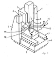
- Fig. 1 shows a coordinate measuring machine 1 with a movable in the X direction measuring table 2, which is slidably mounted on guides 3.
- a portal 4 which has supports 5 and which is designed to be non-displaceable, carries on a traverse 6 a slide 7 which can be displaced in the Y direction and on which in turn a sleeve 8 which is displaceable in the Z direction is arranged.
- the guides 3 and the supports 5 are arranged on a base bed 9 of the coordinate measuring machine 1.
- the carriage 7 and the quill 8 are in Fig. 1 only schematically illustrated to explain the operation of the coordinate measuring machine 1.
- a probe 10 touch sensor
- a button 11 consisting of a rod 13 (spacer), which carries a Tastkugel 12 (probe element) is arranged.
- the button 11 against others, that is switch with a probe shaft and any extensions interchangeable.
- An interface 14 between the probe shaft 13 and the probe 10 is the reference point of the touch sensor.
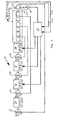
- a controller 15 is provided for the control of the coordinate measuring machine.
- the controller 15 comprises a position controller 16, a speed controller 17 and a current controller 18, wherein the position controller 16 for the position of the axis to be controlled, the speed controller 17 for the speed of the motor drive and the speed controller 17 of the current controller 18 for the driving force or torque of the motor drive is highlighted.
- a scan controller 29 is used in addition to the position controller 16, which holds the deflection of the probe rocker (not shown) relative to the fixed part of the probe 10 constant in terms of magnitude and the position controller 16 is superimposed, that is, the manipulated variable of the scan controller 29 is the desired size of the position controller 16th
- a speed measuring device 20 and a scale 21 actual signals are detected, which are fed into comparison devices 22, 23, 24.
- the scale is replaced by a rotary encoder.
- the actual signals are compared with the supplied desired signals.
- the regulators 16, 17, 18 are according to Fig. 2 for example, designed as a PID controller.
- the controller parameters for controlling the drive unit (not shown) of the axes of the coordinate measuring machine are stored for each probe 11 used with rod 13 and probe ball 12 in a database 26 and are fed to the controller 16, 17, 18.
- Either the properties of the combination of rod 13 (spacer) and probe ball 12 (probe element) used are stored in the database, or the controller parameter sets for the combinations of spacer 13 and probe element 12 used are stored directly.
- controller parameters are used in dependence on the combination of spacer 13 and probe element 12 used in the controllers 16, 17, 18.
- the structural natural frequency a and the natural driving frequency b of the mechanical structure 30 are supplied to the database 26.
- a reaction to the probe 10 is present.
- a method for setting the current D-fraction Kd_akt in the PID position loop for a given current B_akt bender may be performed as follows:
- f R is the natural frequency and d R is the damping of the mechanical structure.
- K D K I / 2 * ⁇ * f R 2 ,
- Kd_min K I ⁇ 2 * ⁇ * F_Z 2
- Kd_max K I ⁇ 2 * ⁇ * f_S 2
- f_Z is greater than f_S.
- n and k are device specific. Depending on how the powers are selected, the nature of the transition between the bending values B_min and B_max is described.
- the advantage of the method and the device according to the invention is that no sensor for the active damping of very low natural frequencies is necessary, whereby a cost saving occurs, the effort is minimized and the system behavior is still robust.
- the controller parameters are not entered from a database, but from a calculation module 27 in the controller 16, 17, 18.
- the calculation module 27 calculates the controller parameters from calibration data of the combination of spacer 13 and probe element 12 in question.
- the elastic properties of this combination of probe element 12 and spacer 13 are determined by repeatedly probing a standard body from different directions, by generating from the deviations of the measurement result from the known values for shape and size of the standard body a matrix 28 which satisfies the elastic properties of the standard describes the questionable combination.
- the standard body is usually a ball of known diameter and known shape deviation.
- the calculated so-called bending matrix has according to Fig. 3 a 3x3 shape. It However, other standard bodies or bending dies or bending functions are conceivable without departing from the scope of the invention.
- a superordinated so-called host software forwards to the control of the coordinate measuring machine 1, which probe 12, 13 is switched in and which calibration matrix 28 is to be used.
- the structural natural frequency a and the natural driving frequency b of the mechanical structure 30 are supplied to the calculation module 27. At the same time a reaction to the probe 10 is present.
Landscapes
- Engineering & Computer Science (AREA)
- Physics & Mathematics (AREA)
- General Physics & Mathematics (AREA)
- Human Computer Interaction (AREA)
- Manufacturing & Machinery (AREA)
- Automation & Control Theory (AREA)
- A Measuring Device Byusing Mechanical Method (AREA)
Abstract
Description
Die Erfindung betrifft ein Verfahren zur Steuerung eines CNC-gesteuerten (computer numeric control) Koordinatenmessgerätes sowie ein Koordinatenmessgerät.The invention relates to a method for controlling a CNC-controlled (computer numeric control) coordinate measuring machine and a coordinate measuring machine.
Zum Stand der Technik (
Weiter gehören zum Stand der Technik rotatorische Achsen wie Drehtische oder so genannte Dreh-Schwenkgelenke, mit Hilfe derer das Werkstück und/oder der Tastkopf um horizontale und/oder vertikale Achsen gedreht werden können.Next to the state of the art include rotary axes such as turntables or so-called rotary swivel joints, by means of which the workpiece and / or the probe can be rotated about horizontal and / or vertical axes.
Wenn im Folgenden von "Achsen" gesprochen wird, so umfasst dieser Begriff alle möglichen Bewegungsachsen von Werkstück und/oder Tastkopf, seien sie linear oder rotatorisch. Der Schutzbereich der Erfindung soll sich ausdrücklich auf alle diese Bewegungsachsen beziehen.When "axes" is used in the following, this term encompasses all possible axes of movement of the workpiece and / or probe, be they linear or rotational. The scope of the invention is expressly related to all of these axes of motion.
Wenn die Achsen den Tastkopf so auf das Werkstück zubewegen, dass das Tastelement mit dem Werkstück in Kontakt kommt, wird die Tastkopfschaukel des Tastkopfes gegenüber seinem festen Teil ausgelenkt, wobei ein Antastsignal ausgelöst oder der Betrag und die Richtung dieser Auslenkung durch eine geeignete Sensorik gemessen wird.When the axes move the probe towards the workpiece so that the probe comes in contact with the workpiece, the probe rocker of the probe is deflected relative to its fixed part, triggering a sounding signal or the amount and direction of this deflection is measured by a suitable sensor.
Im Ruhezustand wird die Tastkopfschaukel durch Rückstellkräfte in einer Ruhestellung gehalten, wobei diese Rückstellkräfte beispielsweise durch Federn oder Kraftgeneratoren, wie beispielsweise Tauchspulensysteme erzeugt werden können.At rest, the probe rocker is held by restoring forces in a rest position, these restoring forces can be generated for example by springs or power generators, such as dive coil systems.
Dadurch, dass das Tastelement zusammen mit dem Abstandsstück und der Tastkopfschaukel eine endliche Masse besitzen, unterliegt es bei Beschleunigung des Tastkopfes Trägheitskräften, die zu einer unerwünscht hohen Auslenkung der Tastkopfschaukel vor der Berührung des Tastelementes mit einem Werkstück führen können.Characterized in that the probe element together with the spacer and the Tastkopfschaukel have a finite mass, it is subject to inertia forces during acceleration of the probe, which can lead to an undesirably high deflection of the Tastkopfschaukel before touching the probe element with a workpiece.
Im so genannten Scanbetrieb, bei dem das Tastelement unter kontinuierlicher Berührung über das Werkstück geführt wird, bildet das Feder-Masse-System, bestehend aus der Masse von Abstandsstück und Tastkopfschaukel, zusammen mit der Biegesteifigkeit des Abstandsstückes ein schwingungsfähiges System, das unter ungünstigen Betriebsbedingungen im Scanbetrieb angeregt wird, was zu Messfehlern führt.In the so-called scanning operation, in which the probe element is guided under continuous contact over the workpiece, the spring-mass system, consisting of the mass of spacer and probe rocker, together with the bending stiffness of the spacer a vibratory system that under unfavorable operating conditions in Scan operation is excited, which leads to measurement errors.
Zum Stand der Technik (
Dieses zum Stand der Technik gehörende Verfahren weist den Nachteil auf, dass beispielsweise bei entsprechender Masse des Tasters die Geschwindigkeit und die Beschleunigung derart angepasst - insbesondere verringert - werden, dass die Gesamtmesszeit sich deutlich erhöht.This belonging to the prior art method has the disadvantage that, for example, with appropriate mass of the probe, the speed and the acceleration adapted in such a way - in particular reduced - that the total measuring time increases significantly.
Weiterhin gehört zum Stand der Technik (
Darüber hinaus gehört zum Stand der Technik (
Weiterhin gehört zum Stand der Technik (
Zum Stand der Technik (
Unter dem Begriff "Reglerparameter" soll hier und im weiteren Verlauf der Anmeldung ausdrücklich weder eine Eingangsgröße (Sollwert) noch eine Stellgröße oder eine Regelgröße (Istwert) verstanden werden, sondern ausschließlich Größen, die die Amplitudenübertragungsfunktion des Reglers im Amplituden-Frequenz-Raum beeinflussen, also zum Beispiel die Kreisverstärkung eines Proportionalreglers.The term "controller parameter" should be understood here and in the further course of the application expressly neither an input variable (setpoint) nor a manipulated variable or a controlled variable (actual value), but only quantities that affect the amplitude transfer function of the controller in the amplitude-frequency space, so for example the loop gain of a proportional controller.
Das der Erfindung zugrunde liegende technische Problem besteht darin, ein Verfahren zur Steuerung eines CNC-gesteuerten Koordinatenmessgerätes anzugeben, bei dem die Anregung des schwingungsfähigen Systems, bestehend aus Tastkopfschaukelmasse inklusive Tastermasse und Tastersteifigkeit (Biegesteifigkeit des Tastelementes mit Abstandsstück) minimiert wird. Darüber hinaus soll ein Koordinatenmessgerät angegeben werden, bei dem die Anregung des schwingungsfähigen Systems, bestehend aus Tastkopfschaukelmasse inklusive Tastermasse und Tastersteifigkeit, minimiert wird.The technical problem underlying the invention is to provide a method for controlling a CNC coordinate measuring machine, wherein the excitation of the oscillatory system, consisting of probe rocker mass including probe mass and probe stiffness (bending stiffness of the probe element with spacer) is minimized. In addition, a coordinate measuring machine is to be specified in which the excitation of the oscillatory system consisting of probe rocker mass including probe mass and probe stiffness is minimized.
Dieses technische Problem wird durch ein Verfahren mit den Merkmalen gemäß Anspruch 1 sowie durch ein Koordinatenmessgerät mit den Merkmalen gemäß Anspruch 11 gelöst.This technical problem is solved by a method having the features according to claim 1 and by a coordinate measuring machine with the features according to
Das erfindungsgemäße Verfahren zur Steuerung eines CNC-gesteuerten Koordinatenmessgerätes mit einer Plattform zur Aufnahme eines Werkstückes mit mindestens einer Struktur, die einen Berührungssensor trägt, wobei diese Struktur mindestens eine erste mechanische Eigenfrequenz aufweist, wobei die Plattform, die das Werkstück aufnimmt und die Struktur, die den Berührungssensor trägt, relativ zueinander beweglich sind, mit einem Taster, bestehend aus wenigstens einem Tastelement und einem Abstandsstück, wobei das Tastelement mit dem Berührungssensor über das Abstandsstück verbunden ist und dessen Berührung mit einem auf der Plattform angeordneten Werkstück von dem Berührungssensor erkannt wird, mit mindestens einer motorischen Antriebseinheit zur Ausführung einer Relativbewegung zwischen dem Werkstück und dem Tastelement, wobei die motorische Antriebseinheit mindestens eine zweite Eigenfrequenz aufweist, die verschieden ist von der ersten Eigenfrequenz der den Berührungssensor tragenden Struktur, mit mindestens einem Regler zur Regelung der Antriebseinheit, wobei der mindestens eine Regler wenigstens einen Reglerparameter aufweist, der die Übertragungsfunktion des Reglers definiert, zeichnet sich dadurch aus, dass mindestens einer der Reglerparameter als Funktion des Abstandes des Tastelementes von einem Referenzpunkt des Berührungssensors und/oder als Funktion von elastischen Eigenschaften des Abstandsstückes in Abhängigkeit des jeweils zum Messen verwendeten Tasters derart verändert wird, dass der Reglerparameter sich zwischen den durch die erste Eigenfrequenz der den Berührungssensor tragenden Struktur und durch die zweite Eigenfrequenz der motorischen Antriebseinheit definierten Grenzen bewegt.The inventive method for controlling a CNC coordinate measuring machine with a platform for receiving a workpiece having at least one structure which carries a touch sensor, said structure having at least a first mechanical natural frequency, wherein the platform which accommodates the workpiece and the structure carries the touch sensor, are movable relative to each other, with a button, consisting of at least one probe element and a spacer, wherein the probe element is connected to the touch sensor on the spacer and its contact with a workpiece arranged on the platform is detected by the touch sensor with at least one motor drive unit for performing a relative movement between the workpiece and the probe element, wherein the motor drive unit has at least one second natural frequency which is different from the first natural frequency of the touch Ensor supporting structure, with at least one controller for controlling the drive unit, wherein the at least one controller has at least one controller parameter that defines the transfer function of the controller, is characterized in that at least one of Controller parameter as a function of the distance of the probe element from a reference point of the touch sensor and / or as a function of elastic properties of the spacer depending on the respective probe used for measuring is changed such that the controller parameter between the first natural frequency of the contact sensor-bearing structure and moved by the second natural frequency of the motor drive unit defined limits.
Mit dem erfindungsgemäßen Verfahren ist es möglich, nach dem Einwechseln eines Tasters, der aus Abstandsstück und Tastelement besteht, die für diesen Taster optimalen Reglerparameter dem Regler vorzugeben, so dass das schwingungsfähige System keine oder lediglich minimale Schwingungen ausführt.With the method according to the invention, it is possible, after replacing a button, which consists of spacer and probe element, the optimal controller parameters for this button predetermine the controller, so that the oscillatory system performs no or only minimal vibrations.
Das Abstandsstück ist üblicherweise ein Stab, der wiederum aus einem Tasterschaft und eventuell aus einer oder mehreren Verlängerungen und Verbindungselementen besteht. Das Tastelement ist üblicherweise eine Tastkugel. Der Taster, der je nach Anforderung an die Messaufgabe eingewechselt wird, besteht aus dem Abstandsstück und dem Tastelement.The spacer is usually a rod, which in turn consists of a probe shaft and possibly one or more extensions and connecting elements. The probe element is usually a Tastkugel. The button, which is changed according to the requirements of the measuring task, consists of the spacer and the probe element.
Der Referenzpunkt bei einem Koordinatenmesssystem ist üblicherweise die Stelle, an der der Taster mit der Tastkopfschaukel verbunden ist. Das heißt, bei einer Tasterlänge gleich Null würde das Tastelement (Tastkugel) im Referenzpunkt angeordnet sein. Gemäß der Erfindung wird der Referenzpunkt dazu genutzt, die Tasterlänge zu bestimmen, da das Koordinatenmessgerät automatisch erkennen soll, wie lang der Taster ist. Ist dem Koordinatenmessgerät die Länge des Tasters oder seine elastischen Eigenschaften (Biegung) bekannt, werden die entsprechenden Reglerparameter in dem mindestens einen Regler zur Regelung der motorischen Antriebseinheiten verändert.The reference point in a coordinate measuring system is usually the point at which the probe is connected to the probe rocker. That is, with a probe length equal to zero, the probe element (probe ball) would be located in the reference point. According to the invention, the reference point is used to determine the probe length, since the coordinate measuring machine should automatically detect how long the probe is. Is the coordinate measuring machine the length of the probe or its elastic properties (bending) As is known, the corresponding controller parameters in the at least one controller for controlling the motor drive units are changed.
Im Einzelnen wird das Verfahren derart ausgeführt, dass der Steuerung der Abstandsvektor des Tastelementes (Tastkugel) vom Referenzpunkt des Berührungssensors und/oder die elastischen Eigenschaften des Abstandsstückes in Abhängigkeit des Tasters mitgeteilt werden, worauf die Steuerung hieraus Reglerparameter generiert, die beim Verfahren der Achsen des Koordinatenmessgerätes zum Zwecke der Antastung oder des Scannens verwendet werden.In detail, the method is carried out such that the control of the distance vector of the probe element (probe ball) from the reference point of the touch sensor and / or the elastic properties of the spacer are communicated in response to the button, whereupon the controller generates therefrom controller parameters, which in the process of the axes of the Coordinate measuring device can be used for the purpose of probing or scanning.
Die Eingabe der Eigenschaften von Abstandsstück in Verbindung mit dem Tastelement kann manuell, zum Beispiel über eine Tastatur oder automatisch erfolgen, indem die Steuerung ein Berechnungsmodul umfasst, das aus den Kalibrierdaten der fraglichen Kombination aus Abstandsstück und Tastelement die Reglerparameter berechnet.The input of the properties of spacer in connection with the probe element can be done manually, for example via a keyboard or automatically, in that the controller comprises a calculation module which calculates the controller parameters from the calibration data of the combination of spacer and probe element in question.
Unter Kalibrieren wird in diesem Zusammenhang ein gemäß dem Stand der Technik bekannter Vorgang verstanden, bei dem die elastischen Eigenschaften einer Kombination aus Tastelement und Abstandsstück durch mehrfaches Antasten eines Normkörpers aus verschiedenen Richtungen dadurch bestimmt werden, dass aus den Abweichungen des Messergebnisses von den bekannten Werten zur Form und Größe des Normkörpers eine Matrix erzeugt wird, die die elastischen Eigenschaften der fraglichen Kombination aus Tastelement und Abstandsstück beschreibt. Der Normkörper ist üblicherweise eine Kugel mit bekanntem Durchmesser und bekannter Formabweichung. Die berechnete Matrix besitzt üblicherweise eine 3x3-Gestalt.Calibration is understood in this context to be a process known from the prior art, in which the elastic properties of a combination of probe element and spacer are determined by repeatedly probing a standard body from different directions by determining from the deviations of the measurement result from the known values Form and size of the standard body is generated a matrix that describes the elastic properties of the questionable combination of probe element and spacer. The standard body is usually a ball of known diameter and known shape deviation. The calculated matrix usually has a 3x3 shape.
Gemäß einer vorteilhaften Ausführungsform kann das erfindungsgemäße Verfahren beim gesteuerten Scannen eingesetzt werden. Beim gesteuerten Scannen wird der Tastkopf entlang einer durch Soll-Daten vorgegebenen Bahn geführt und die Abweichung der Ist- von der Soll-Kontur gemessen.According to an advantageous embodiment, the method according to the invention can be used in controlled scanning. In controlled scanning, the probe is guided along a predetermined by target data path and the deviation of the actual measured from the target contour.
Das erfindungsgemäße Verfahren kann vorteilhaft jedoch auch beim geregelten Scannen eingesetzt werden. Beim geregelten Scannen wird die Auslenkung des Tastkopfes in einem Regelkreis auf einen Sollwert geregelt. Zur Steuerung wird lediglich eine Fläche vorgegeben, die die Werkstückoberfläche schneidet und in der die Tastkugel geführt wird. Dieses Verfahren ist universell einsetzbar jedoch schwingungsanfällig, da hierbei über das gesamte Koordinatenmessgerät ein Regelkreis geschlossen werden muss, in den aus der gescannten Kontur beliebige Frequenzen eingekoppelt werden. Die erreichbare Geschwindigkeit ist bei gegebener Genauigkeit daher durch die Dynamik des Gesamtsystems begrenzt.However, the method according to the invention can advantageously also be used in controlled scanning. In controlled scanning, the deflection of the probe is controlled in a control loop to a setpoint. For control, only a surface is predetermined, which cuts the workpiece surface and in which the probe ball is guided. However, this method is universally applicable but susceptible to vibration, since in this case a control loop must be closed over the entire coordinate measuring machine, in which arbitrary frequencies are coupled from the scanned contour. The achievable speed is therefore limited by the dynamics of the overall system given the accuracy.
Geregeltes Scannen reagiert empfindlich auf verschiedene schwingungsfähige Maschinenstrukturen, die beispielsweise durch Antriebe, die nicht im Schwerpunkt der jeweiligen Struktur angreifen, zu Schwingungen angeregt werden.Regulated scanning is sensitive to various vibratory machine structures, which are excited to vibrate, for example by drives that do not attack in the center of gravity of the respective structure.
Dies gilt insbesondere für große weiche Strukturen mit schwingungsfähigen Elementen (sehr niedrige Eigenfrequenzen), deren Einfluss nicht in den Führungsübertragungsfunktionen der Antriebszüge der einzelnen Achsen auftreten und somit nur mittels zusätzlicher teurer Sensoren (zum Beispiel Beschleunigungssensoren) inklusive aufwändiger Signalverarbeitung online erfasst und bedämpft werden können.This is especially true for large soft structures with oscillatory elements (very low natural frequencies) whose influence does not occur in the leadership transfer functions of the drive trains of the individual axes and thus can only be detected and attenuated online by means of additional expensive sensors (eg acceleration sensors) including complex signal processing.
Zur Lösung dieses Problems werden mit dem erfindungsgemäßen Verfahren die Führungsübertragungsfunktionen der Antriebsregler mittels Parameteradaption so eingestellt, dass der Einfluss der nicht erfassten schwingungsfähigen Maschinenstrukturen auf das Scanergebnis minimiert wird:
- Bei weichen (langen) Tastern finden sich niederfrequente Maschinenstrukturschwingungen hauptsächlich in der Tasterbiegung wieder, das heißt, die Auslenkung der Tastkopfschaukel wird nur im geringen Maße von der Maschinenstruktur beeinflusst. Daraus folgt, dass eine Parameterabstimmung auf die offline/online ermittelte Parameterabstimmung auf die offline/online ermittelte Eigenfrequenz der Antriebskomponenten das bestmögliche Ergebnis bringt.
- Bei steifen (kurzen) Tastern wird die Tastkopfschaukel stärker von der niederfrequenten Maschinenstrukturschwingung beeinflusst. In diesem Fall bringt eine Parameterabstimmung auf die offline ermittelte Frequenz der Maschinenstrukturschwingung das bestmögliche Ergebnis.
- With soft (long) keys, low-frequency machine structure oscillations are mainly found in the probe bend, that is, the deflection of the probe head swing is only slightly influenced by the machine structure. It follows that a parameter adjustment to the offline / online determined parameter tuning to the offline / online determined natural frequency of the drive components brings the best possible result.
- For stiff (short) buttons, the probe rocker is more affected by the low frequency machine structure vibration. In this case, parameter tuning to the off-line frequency of the machine structure vibration provides the best possible result.
Gemäß einer vorteilhaften Ausführungsform der Erfindung wird als Berührungssensor ein schaltender Tastkopf oder ein messender Tastkopf verwendet.According to an advantageous embodiment of the invention, a switching probe or a measuring probe is used as a touch sensor.
Gemäß einer weiteren vorteilhaften Ausführungsform der Erfindung wird ein Regler mit einer Kaskadenstruktur verwendet, wobei ein Lageregler für die Lage einer zu regelnden Achse, ein Geschwindigkeitsregler für die Geschwindigkeit einer die zu regelnde Achse antreibenden motorischen Antriebseinheit (konventioneller Motor oder Linearmotor) und ein Stromregler für die Antriebskraft oder das Antriebsdrehmoment vorgesehen sind. Dem Lageregler ist der Geschwindigkeitsregler und dem Geschwindigkeitsregler ist der Stromregler unterlegt.According to a further advantageous embodiment of the invention, a controller is used with a cascade structure, wherein a position controller for the position of an axis to be controlled, a speed controller for the speed of the axis to be controlled driving motor drive unit (conventional motor or linear motor) and a current controller for the Driving force or the driving torque are provided. The position controller is the speed controller and the speed controller is underlain by the current controller.
Während der kontinuierlichen Abtastung eines Werkstückes (Scanbetrieb) wird zusätzlich zum Lageregler ein Scanregler verwendet, der die Auslenkung der Tastkopfschaukel relativ zum festen Teil des Tastkopfes betragsmäßig konstant hält und dem Lageregler überlagert ist, das heißt, die Stellgröße des Scanreglers ist die Sollgröße des Lagereglers. Es ist auch möglich, als Regler anstelle des Kaskadenreglers einen Zustandsregler zu verwenden.During continuous scanning of a workpiece (scan mode), a scan controller is used in addition to the position controller used, which holds the deflection of the probe rocker relative to the fixed part of the probe constant in terms of magnitude and is superimposed on the position controller, that is, the manipulated variable of the scan controller is the target size of the position controller. It is also possible to use a state controller instead of the cascade controller as a controller.
Gemäß einer weiteren vorteilhaften Ausgestaltung der Erfindung wird als Regler ein digitaler Regler verwendet.According to a further advantageous embodiment of the invention, a digital controller is used as a controller.
Gemäß einer weiteren vorteilhaften Ausführungsform der Erfindung wird wenigstens ein Reglerparameter des Lagereglers oder des Geschwindigkeitsreglers oder des Stromreglers als Funktion des Abstandes des Tastelementes von dem Referenzpunkt des Berührungssensors und/oder als Funktion der elastischen Eigenschaften des Abstandsstückes verändert.According to a further advantageous embodiment of the invention, at least one controller parameter of the position controller or of the speed controller or of the current controller is changed as a function of the distance of the probe element from the reference point of the contact sensor and / or as a function of the elastic properties of the spacer.
Gemäß einer weiteren vorteilhaften Ausgestaltung der Erfindung wird eine Kombination aus Reglerparametern von Lageregler und/oder Geschwindigkeitsregler und/oder Stromregler als Funktion des Abstandes des Tastelementes von dem Referenzpunkt des Berührungssensors und/oder als Funktion der elastischen Eigenschaften des Abstandsstückes in Abhängigkeit der eingewechselten Tasterkombination derart verändert, dass der Reglerparameter sich zwischen den durch die erste Eigenfrequenz der den Berührungssensor tragenden Struktur und durch die zweite Eigenfrequenz der motorischen Antriebseinheit definierten Grenzen bewegt.According to a further advantageous embodiment of the invention, a combination of controller parameters of position controller and / or speed controller and / or current controller as a function of the distance of the probe element from the reference point of the touch sensor and / or changed as a function of the elastic properties of the spacer depending on the substitute push-button combination in that the controller parameter moves between the limits defined by the first natural frequency of the structure bearing the contact sensor and the limits defined by the second natural frequency of the motorized drive unit.
Eine weitere Möglichkeit, die Steuerung über die Eigenschaften der verwendeten Kombination aus Abstandsstück und Tastelement zu informieren, besteht darin, dass die ein Gewicht und eine Steifigkeit charakterisierenden Größen von Tastelementen und Abstandsstücken in einer Datenbank abgespeichert sind und beim Einwechseln der jeweiligen Kombination aus Tastelement und Abstandsstück automatisch zu einer Anpassung der Reglerparameter führen. In der Datenbank sind entweder die genannten Eigenschaften oder direkt die Reglerparametersätze der zu verwendenden Kombinationen aus Abstandsstück und Tastelement abgelegt.Another way to inform the controller about the properties of the combination of spacer and probe element used is that the variables characterizing a weight and a rigidity of scanning elements and spacers are stored in a database are and when changing the respective combination of probe element and spacer automatically lead to an adjustment of the controller parameters. In the database, either the mentioned properties or directly the controller parameter sets of the combinations of spacer and probe element to be used are stored.
Gemäß einer weiteren vorteilhaften Ausführungsform der Erfindung werden die zur Anpassung der Reglerparameter notwendigen charakteristischen Größen aus einem Ergebnis einer Tasterkalibrierung gewonnen.According to a further advantageous embodiment of the invention, the characteristic variables necessary for adapting the controller parameters are obtained from a result of a probe calibration.
Vorteilhaft werden die Reglerparameter während eines Scanlaufes kontinuierlich angepasst.Advantageously, the controller parameters are continuously adjusted during a scan.
Die Erfindung betrifft darüber hinaus ein Koordinatenmessgerät mit einer Plattform zur Aufnahme eines Werkstückes mit mindestens einer Struktur, die einen Berührungssensor trägt, wobei diese Struktur mindestens eine erste mechanische Eigenfrequenz aufweist, wobei die Plattform, die das Werkstück aufnimmt und die Struktur, die den Berührungssensor trägt, relativ zueinander beweglich sind, mit einem Taster, bestehend aus wenigstens einem Tastelement und einem Abstandsstück, wobei das Tastelement mit dem Berührungssensor über das Abstandsstück verbunden ist und dessen Berührung mit einem auf der Plattform angeordneten Werkstück von dem Berührungssensor erkannt wird, mit einer motorischen Antriebseinheit zur Ausführung der Relativbewegung zwischen dem Werkstück und dem Tastelement, wobei die motorische Antriebseinheit mindestens eine zweite Eigenfrequenz aufweist, die verschieden ist von der ersten Eigenfrequenz der den Berührungssensor tragenden Struktur, mit einer Steuerung, die mindestens einen Regler zur Regelung der Antriebseinheit aufweist, wobei der mindestens eine Regler wenigstens einen Reglerparameter aufweist, der die Übertragungsfunktion des Reglers definiert, zeichnet sich dadurch aus, dass das Koordinatenmessgerät eine Berechnungseinheit aufweist, die als eine die die Übertragungsfunktion des wenigstens einen Reglers charakterisierenden Reglerparameter als Funktion des Abstandes des Tastelementes von einem Referenzpunkt des Berührungssensors und/oder als Funktion von elastischen Eigenschaften des Abstandsstückes in Abhängigkeit von der jeweils eingewechselten Tasterkombination verändernde Berechnungseinheit ausgebildet ist, und dass die Berechnungseinheit als eine den mindestens einen Reglerparameter derart verändernde Berechnungseinheit ausgebildet ist, dass der Reglerparameter sich zwischen den durch die erste Eigenfrequenz der den Berührungssensor tragenden Struktur und durch die zweite Eigenfrequenz der motorischen Antriebseinheit definierten Grenzen bewegt.The invention further relates to a coordinate measuring machine having a platform for receiving a workpiece with at least one structure carrying a touch sensor, said structure having at least a first mechanical natural frequency, the platform receiving the workpiece and the structure supporting the touch sensor are movable relative to each other, with a stylus, comprising at least one probe element and a spacer, wherein the probe element is connected to the touch sensor via the spacer and its contact with a workpiece arranged on the platform is detected by the touch sensor, with a motor drive unit for carrying out the relative movement between the workpiece and the probe element, wherein the motor drive unit has at least one second natural frequency, which is different from the first natural frequency of the structure carrying the touch sensor, with a control tion, which has at least one controller for controlling the drive unit, wherein the at least one Controller has at least one controller parameter that defines the transfer function of the controller, characterized in that the coordinate measuring machine has a calculation unit which is a controller characterizing the transfer function of the at least one controller parameter as a function of the distance of the probe element from a reference point of the touch sensor and / or is formed as a function of elastic properties of the spacer depending on the respectively substituted switch combination changing calculation unit, and that the calculation unit is designed as a the at least one controller parameter such changing calculation unit that the controller parameter between the first natural frequency of the touch sensor bearing Structure and limits defined by the second natural frequency of the motor drive unit limits.
Unter der "motorischen Antriebseinheit" wird hier und im weiteren Verlauf der Anmeldung ausdrücklich nicht nur der Motor verstanden, sondern zusätzlich die gesamte mechanische Übertragungsstrecke vom Motor bis zur Ankopplung an die zu bewegende Struktur, wie zum Beispiel Übersetzungsgetriebe.The "motor drive unit" is here and in the further course of the application expressly understood not only the engine, but in addition the entire mechanical transmission path from the engine to the coupling to the structure to be moved, such as transmission gear.
Gemäß einer besonders bevorzugten Ausführungsform der Erfindung weist die Steuerung zusätzlich eine Datenbank auf, in der die ein Gewicht und eine Steifigkeit charakterisierenden Größen von Tastelementen und Abstandsstücken für verschiedene Kombinationen von Tastelementen und Abstandsstücken abgelegt sind und bei Verwendung der jeweiligen Kombination zur Berechnung der Reglerparameter herangezogen werden.According to a particularly preferred embodiment of the invention, the controller additionally has a database in which the variables of probe elements and spacers characterizing a weight and a rigidity are stored for different combinations of probe elements and spacers and are used to calculate the controller parameters when using the respective combination ,
Gemäß einer weiteren vorteilhaften Ausgestaltung der Erfindung weist die Steuerung ein Modul auf, das als ein die Ergebnisse einer Tasterkalibrierung zur Berechnung der Reglerparameter verwendendes Modul ausgebildet ist.According to a further advantageous embodiment of the invention, the controller has a module that is designed as a module that uses the results of a probe calibration for calculating the controller parameters.
Der Berührungssensor ist vorteilhaft als schaltender Tastkopf oder als messender Tastkopf ausgebildet.The touch sensor is advantageously designed as a switching probe or as a measuring probe.
Das Koordinatenmessgerät weist vorteilhaft drei lineare bewegliche Achsen auf, die ein kartesisches Koordinatensystem aufspannen. Es ist jedoch auch möglich, ein Koordinatenmessgerät in parallelkinematischer Bauweise, wie zum Beispiel Hexapoden, einzusetzen.The coordinate measuring machine advantageously has three linear movable axes which span a Cartesian coordinate system. However, it is also possible to use a coordinate measuring machine in parallel kinematic construction, such as hexapods.
Gemäß einer vorteilhaften Ausführungsform der Erfindung weist der Regler eine Kaskadenstruktur auf, wobei ein Lageregler für die Lage der zu regelnden Achse, ein Geschwindigkeitsregler für die Geschwindigkeit des die zu regelnde Achse antreibenden motorischen Antriebes und ein Stromregler für die Antriebskraft oder das Drehmoment des motorischen Antriebes vorgesehen sind. Dem Lageregler ist der Geschwindigkeitsregler und dem Geschwindigkeitsregler ist der Stromregler unterlegt.According to an advantageous embodiment of the invention, the controller has a cascade structure, wherein a position controller for the position of the axis to be controlled, a speed controller for the speed of the axis to be controlled driving motor drive and a current controller for the driving force or the torque of the motor drive provided are. The position controller is the speed controller and the speed controller is underlain by the current controller.
Der Regler kann gemäß einer besonders bevorzugten Ausführungsform auch als Zustandsregler ausgebildet sein. In jedem Falle handelt es sich bei den zu ändernden Parametern um Parameter, die die Übertragungsfunktion des jeweiligen Reglers beeinflussen. Vorteilhaft ist der Regler als digitaler Regler ausgebildet.The controller may also be designed as a state controller according to a particularly preferred embodiment. In any case, the parameters to be changed are parameters which influence the transfer function of the respective controller. Advantageously, the controller is designed as a digital controller.
Weitere Merkmale und Vorteile der Erfindung ergeben sich anhand der zugehörigen Zeichnung, in der ein Ausführungsbeispiel eines erfindungsgemäßen Koordinatenmessgerätes nur beispielhaft dargestellt ist. In der Zeichnung zeigen:
- Fig. 1
- ein Koordinatenmessgerät in Portalbauweise in perspektivischer Ansicht;
- Fig. 2
- eine Prinzipdarstellung einer Regelung mit in einer Datenbank abgespeicherten Taster- daten;
- Fig. 3
- eine grafische Darstellung der Biegungs- werte, aufgetragen gegen die Wichtungsfakto- ren;
- Fig. 4
- eine Prinzipdarstellung einer Regelung mit einem Berechnungsmodul aufgrund von Kali- brierdaten.
- Fig. 1
- a coordinate measuring machine in gantry design in perspective view;
- Fig. 2
- a schematic diagram of a control with stored in a database probe data;
- Fig. 3
- a graphic representation of the bending values plotted against the weighting factors;
- Fig. 4
- a schematic diagram of a control with a calculation module based on calibration data.
An der Pinole 8 ist ein Tastkopf 10 (Berührungssensor) angeordnet, an dem ein Taster 11, bestehend aus einem Stab 13 (Abstandsstück), der eine Tastkugel 12 (Tastelement) trägt, angeordnet ist. Grundsätzlich ist der Taster 11 gegen andere, das heißt Taster mit einem Tasterschaft und eventuellen Verlängerungen auswechselbar. Eine Schnittstelle 14 zwischen dem Tasterschaft 13 und dem Tastkopf 10 stellt den Referenzpunkt des Berührungssensors dar.At the
Im Scanbetrieb, bei dem die Tastkugel 12 unter kontinuierlicher Berührung über ein Werkstück (nicht dargestellt) geführt wird, wobei das Werkstück auf dem Messtisch 2 angeordnet ist, bildet das Feder-Masse-System, bestehend aus der Masse des Abstandsstückes 13 in Verbindung mit der Masse des beweglichen Tastkopfteiles zusammen mit der Biegesteifigkeit des Abstandsstückes 13 ein schwingungsfähiges System, das unter ungünstigen Betriebsbedingungen im Scanbetrieb angeregt wird, was wiederum zu Messfehlern führt.In scanning operation, in which the
Um ein Aufschwingen dieses Systems zu vermeiden in Abhängigkeit von dem eingewechselten Taster 11, ist gemäß
Während der kontinuierlichen Abtastung eines Werkstückes (Scanbetrieb) wird zusätzlich zum Lageregler 16 ein Scanregler 29 verwendet, der die Auslenkung der Tastkopfschaukel (nicht dargestellt) relativ zum festen Teil des Tastkopfes 10 betragsmäßig konstant hält und dem Lageregler 16 überlagert ist, das heißt, die Stellgröße des Scanreglers 29 ist die Sollgröße des Lagereglers 16.During the continuous scanning of a workpiece (scan mode), a
Von einer Strommessvorrichtung 19, einer Geschwindigkeitsmessvorrichtung 20 und einem Maßstab 21 werden Ist-Signale erfasst, die in Vergleichsvorrichtungen 22, 23, 24 eingespeist werden. Im Falle rotatorischer Achsen wird der Maßstab durch einen Drehwinkelgeber ersetzt.From a
In den Vergleichsvorrichtungen 22, 23, 24, 25 werden die Ist-Signale mit den eingespeisten Soll-Signalen verglichen.In the
Die Regler 16, 17, 18 sind gemäß
Das bedeutet, dass die Reglerparameter in Abhängigkeit der verwendeten Kombination aus Abstandsstück 13 und Tastelement 12 in den Reglern 16, 17, 18 verwendet werden.This means that the controller parameters are used in dependence on the combination of
Die Struktureigenfrequenz a und die Antriebseigenfrequenz b der mechanischen Struktur 30 werden der Datenbank 26 zugeführt. Darüber hinaus ist eine Rückwirkung auf den Tastkopf 10 vorhanden.The structural natural frequency a and the natural driving frequency b of the
Für den Ablauf der Parameteradaption wird folgendes Beispiel angegeben:
- (S) Offline-Bestimmung von Eigenfrequenz: f_S und Dämpfung: d_S der Maschinenstrukturen mit sehr niedrigen Eigenfrequenzen und Berechnen der zugehörigen Parametergrenzen für ein robustes Reglerverhalten.
- (Z) Offline-/Online-Bestimmung von Eigenfrequenz: f_Z und Dämpfung: d_Z der Antriebszüge und Berechnen der zugehörigen Parametergrenzen für ein robustes Reglerverhalten. Dies geschieht mit Hilfe der ohnehin vorhandenen Standardzustandssensoren, wie Längenschrittgeber für die Achsen und Tacho für den Motor.
- (T) Online-Erfassung der Tastkopfschwingungen (Frequenz: f_T, Dämpfung: d_T) über die Auslenkung der Tastkopfschaukel.
- (B) Online-Erfassung der Biegungswerte (= reziproke Steifigkeit) des jeweils eingesetzten zulässigen Tasters über die Steuersoftware innerhalb der zulässigen Biegungswertgrenzen B_min und B_max oder Offline-Erfassung über die Länge.
- (P) Online-Parameteradaption (Algorithmus).
- (S) Offline determination of natural frequency: f_S and damping: d_S of the machine structures with very low natural frequencies and calculation of the associated parameter limits for a robust controller behavior.
- (Z) Offline / online determination of natural frequency: f_Z and damping: d_Z of the drive trains and calculation of the associated parameter limits for a robust controller behavior. This is done with the help of the already existing standard condition sensors, such as length encoders for the axles and speedometer for the engine.
- (T) Online detection of the probe vibrations (frequency: f_T, damping: d_T) via the deflection of the probe rocker.
- (B) Online recording of the bending values (= reciprocal stiffness) of the respectively used permissible probe via the control software within the permissible bending value limits B_min and B_max or offline acquisition over the length.
- (P) Online parameter adaptation (algorithm).
Mit
- S =
- schwingungsfähige Maschinenstruktur
- Z =
- Standard-Zustandssensor
- T =
- Tastkopf
- B =
- Tasterbiegung
- P =
- Parameter.
- S =
- vibratory machine structure
- Z =
- Standard state sensor
- T =
- probe
- B =
- probe bending
- P =
- Parameter.
Ein Verfahren zum Einstellen des aktuellen D-Anteils Kd_akt im PID-Positionsregelkreis für eine gegebene aktuelle Tasterbiegung B_akt kann folgendermaßen durchgeführt werden:A method for setting the current D-fraction Kd_akt in the PID position loop for a given current B_akt bender may be performed as follows:
Offline-Bestimmung der Eigenfrequenzen:
- f_S =
- Eigenfrequenz der Maschinenstruktur
- f_Z =
- Eigenfrequenz des Antriebszuges
- f_S =
- Natural frequency of the machine structure
- f_Z =
- Natural frequency of the drive train
Die Laplacetransformierte der Übertragungsfunktion eines PID-Reglers lautet: ![]()
![]()
Die Laplacetransformierte der Übertragungsfunktion einer allgemeinen schwingungsfähigen mechanischen Struktur lautet: ![]()
![]()
Hierbei ist fR die Eigenfrequenz und dR die Dämpfung der mechanischen Struktur.Here, f R is the natural frequency and d R is the damping of the mechanical structure.
Durch Koeffizientenvergleich erhält man KD zu ![]()
![]()
Auf dieses Beispiel bezogen errechnen sich die zulässigen Parametergrenzen zu ![]()
![]()
Hierbei ist f_Z größer als f_S.Based on this example, the permissible parameter limits are calculated ![]()
![]()
Here, f_Z is greater than f_S.
Mit den Biegungswertgrenzen aus dem zulässigen Tastersortiment
B_min und B_max
errechnet sich der aktuelle D-Anteil über die Funktion h() und den Wichtungsfaktoren g1 und g2 zu ![]()
B_min and B_max
the current D-component is calculated using the function h () and the weighting factors g1 and g2 ![]()
Es hat sich gezeigt, dass mit ![]()
![]()
![]()
![]()
wobei n und k ganze Zahlen sind,
ein zuverlässiges und robustes Scannen mit allen Tastern aus dem zulässigen Tastersortiment auch ohne zusätzliche teure Sensoren und aufwändiger Signalverarbeitung möglich ist.It has been shown that with ![]()
![]()
![]()
![]()
where n and k are integers,
Reliable and robust scanning with all buttons from the permissible probe range is possible even without additional expensive sensors and complex signal processing.
Die Wahl der Potenzen n und k ist gerätespezifisch. Je nachdem, wie die Potenzen ausgewählt werden, wird die Art des Überganges zwischen den Biegungswerten B_min und B_max beschrieben.The choice of powers n and k is device specific. Depending on how the powers are selected, the nature of the transition between the bending values B_min and B_max is described.
Für n = 1 und k = 1 ist der Übergang in
Auf diese Weise können bei Bedarf alle in der Reglerkaskade vorhandenen, die Übertragungsfunktion des Reglers charakterisierenden Parameter innerhalb ihrer zulässigen Grenzen, die durch die Eigenfrequenzen von Maschinenstruktur und Antriebszug sowie der zulässigen Biegungsgrenzen für die Taster bestimmt werden, so variiert werden, dass das Scanverhalten für jeden aktuellen Tasterbiegungswert optimal ist.In this way, if necessary, all parameters characterizing the transfer function of the controller within its allowable limits, which are determined by the natural frequencies of machine structure and drive train and the permissible bending limits for the buttons, can be varied so that the scanning behavior for each current Basterbiegungswert is optimal.
Der Vorteil des erfindungsgemäßen Verfahrens und der erfindungsgemäßen Vorrichtung besteht darin, dass kein Sensor für die aktive Bedämpfung sehr niedriger Eigenfrequenzen notwendig ist, wodurch eine Kostenersparnis auftritt, der Aufwand minimiert wird und das Systemverhalten trotzdem robust ist.The advantage of the method and the device according to the invention is that no sensor for the active damping of very low natural frequencies is necessary, whereby a cost saving occurs, the effort is minimized and the system behavior is still robust.
Gemäß
Beispielsweise leitet eine übergeordnete so genannte Hostsoftware an die Steuerung des Koordinatenmessgerätes 1 weiter, welcher Taster 12, 13 eingewechselt ist und welche Kalibriermatrix 28 zu verwenden ist.For example, a superordinated so-called host software forwards to the control of the coordinate measuring machine 1, which
Die Struktureigenfrequenz a und die Antriebseigenfrequenz b der mechanischen Struktur 30 werden dem Berechnungsmodul 27 zugeführt. Gleichzeitig ist eine Rückwirkung auf den Tastkopf 10 vorhanden.The structural natural frequency a and the natural driving frequency b of the
- 11
- Koordinatenmessgerätcoordinate measuring machine
- 22
- Messtisch (Plattform)Measuring table (platform)
- 33
- Führungenguides
- 44
- Portalportal
- 55
- StützenSupport
- 66
- Traversetraverse
- 77
- Schlittencarriage
- 88th
- PinolePinole
- 99
- Grundbettbasic bed
- 1010
- Tastkopf (Berührungssensor)Probe (touch sensor)
- 1111
- Tasterbutton
- 1212
- Tastkugel (Tastelement)Tastkugel (probe element)
- 1313
- Stab (Abstandsstück)Rod (spacer)
- 1414
-
Referenzpunkt des Berührungssensors 10Reference point of the
touch sensor 10 - 1515
- Reglerregulator
- 1616
- Lagereglerposition controller
- 1717
- Geschwindigkeitsreglercruise control
- 1818
- Stromreglercurrent regulator
- 1919
- StrommessvorrichtungCurrent measuring device
- 2020
- Geschwindigkeitsmesserspeedometer
- 2121
- Maßstab oder WinkelgeberScale or angle encoder
- 2222
- Vergleichsvorrichtungcomparison means
- 2323
- Vergleichsvorrichtungcomparison means
- 2424
- Vergleichsvorrichtungcomparison means
- 2525
- StelleJob
- 2626
- DatenbankDatabase
- 2727
- Berechnungsmodulcalculation module
- 2828
- Matrixmatrix
- 2929
- Scanreglerscan controller
- 3030
- mechanische Strukturmechanical structure
- aa
- StruktureigenfrequenzStructural natural frequency
- bb
- AntriebseigenfrequenzDrive natural frequency
Claims (20)
- A method of controlling a CNC-controlled coordinate measuring apparatus (1)- having a platform (2) to receive a workpiece,- having at least one structure, which bears a contact sensor (10),- wherein this structure has at least a first mechanical natural frequency,- wherein the platform (2), receiving the workpiece, and the structure, bearing the contact sensor (10), are movable relative to one another,- having a probe device (11), consisting of at least one probe element (12) and a distance piece (13), wherein the probe element is connected to the contact sensor via the distance piece and its contact with a workpiece arranged on the platform is detected by the contact sensor (10),- having at least one motive drive unit for effecting a relative motion between the workpiece and the probe element (12)- wherein the motive drive unit has at least a second natural frequency, differing from the first natural frequency of the structure bearing the contact sensor,- having at least one regulator (15) for regulating the drive unit, wherein the at least one regulator has at least one regulator parameter defining a transfer function of the regulator,
characterised in that at least one of the regulator parameters is, as a function of the distance of the probe element (12) from a reference point (14) of the contact sensor (10) and/or as a function of elastic properties of the distance piece (13), altered dependent on the probe device (11) used for measuring in each case in such a manner that the regulator parameter moves between the thresholds defined by the first natural frequency of the structure bearing the contact sensor and by the second natural frequency of the motive drive unit. - A method according to claim 1, characterised in that a switching probe head (10) or a measuring probe head is used as contact sensor (10).
- A method according to any one of the preceding claims, characterised in that a regulator (15) with a cascade structure is used, wherein a position regulator (16) for the position of an axis to be regulated, a speed regulator (17) for the speed of the motive drive unit and a current regulator (18) for the driving force or the torque of the motive drive unit are provided, and in that the speed regulator (17) is subordinate to the position regulator (16) and the current regulator (18) is subordinate to the speed regulator (17).
- A method according to claim 3, characterised in that a scan regulator (29) is superimposed on the position regulator (16).
- A method according to any one of claims 1 and 2, characterised in that a state regulator or a digital regulator is used as regulator (15).
- A method according to any one of claims 3 and 4, characterised in that at least one regulator parameter of the scan regulator (29) or the position regulator (16) or the speed regulator (17) or the current regulator (18) is, as a function of the distance of the probe element (12) from the reference point (14) of the contact sensor (10) and/or as a function of the elastic properties of the distance piece (13), altered dependent on the probe combination changed in each case.
- A method according to any one of claims 3 and 4, characterised in that a combination of regulator parameters of scan regulator (29) and/or position regulator (16) and/or speed regulator (17) and/or current regulator (18) is, as a function of the distance of the probe element (12) from the reference point (14) of the contact sensor (10) and/or as a function of the elastic properties of the distance piece (13), altered dependent on the probe combination changed in each case
- A method according to any one of the preceding claims, characterised in that the values, characterising weight and stiffness, of probe elements (12) and distance pieces (13) are stored in a data bank (26) and, upon changing of the current combination of probe element (12) and distance piece (13), are automatically used to adapt the regulator parameters.
- A method according to any one of claims 6 and 7, characterised in that the characteristic values necessary for adaptation of the regulator parameters are obtained from a result of a probe calibration.
- A method according to any one of the preceding claims, characterised in that the regulator parameters are adapted continuously during a scan operation.
- A coordinate measuring apparatus (1)- having a platform (2) to receive a workpiece,- having at least one structure, which bears a contact sensor (10),- wherein this structure has at least a first mechanical natural frequency,- wherein the platform, receiving the workpiece, and the structure, bearing the contact sensor (10), are movable relative to one another,- having a probe device (11), consisting of at least one probe element (12) and a distance piece, wherein the probe element (12) is connected to the contact sensor (10) via the distance piece and its contact with a workpiece arranged on the platform is detected by the contact sensor (10),- having a motive drive unit for effecting the relative motion between the workpiece and the probe element (12),- wherein the motive drive unit has at least a second natural frequency, differing from the first natural frequency of the structure bearing the contact sensor,- having a control means with at least one regulator (15) to regulate the motive drive unit,- wherein the at least one regulator (15) has at least one regulator parameter defining the transfer function of the at least one regulator,
characterised in that the coordinate measuring apparatus (1) has a calculation unit (27), which is in the form of a calculation unit altering the regulator parameters characterising the transfer function of the at least one regulator, as a function of the distance of the probe element (12) from a reference point (14) of the contact sensor (10) and/or as a function of elastic properties of the distance piece (13), dependent on the probe combination changed in each case, and in that the calculation unit (27) is in the form of a calculation unit altering the at least one regulator parameter in such a manner that the regulator parameter moves between the thresholds defined by the first natural frequency of the structure bearing the contact sensor and by the second natural frequency of the motive drive unit. - A coordinate measuring apparatus (1) according to claim 11, characterised in that the control means additionally has a data bank (26) in which the values, characterising weight and stiffness, of probe elements (12) and distance pieces (13) are stored for different combinations of probe elements (12) and distance pieces (13) and are retrieved to calculate the regulator parameters when the respective combination is used.
- A coordinate measuring apparatus (1) according to claim 11, characterised in that the control means has a module in the form of a module using the results (28) of a probe calibration to calculate the regulator parameters.
- A coordinate measuring apparatus (1) according to claim 11, characterised in that the contact sensor (10) is in the form of a switching probe or a measuring probe.
- A coordinate measuring apparatus (1) according to claim 11, characterised in that the coordinate measuring apparatus has three linear movable axes (X, Y, Z) spanning a Cartesian coordinate system.
- A coordinate measuring apparatus (1) according to claim 15, characterised in that the coordinate measuring apparatus additionally has at least one rotatory axis.
- A coordinate measuring apparatus (1) according to claim 11, characterised in that the coordinate measuring apparatus solely has rotatory axes.
- A coordinate measuring apparatus (1) according to claim 11, characterised in that the regulator (15) has a cascade structure, wherein a position regulator (16) for the position of an axis to be regulated, a speed regulator (17) for the motive drive unit and a current regulator (18) are provided, and in that the speed regulator (17) is subordinate to the position regulator (16) and the current regulator (18) is subordinate to the speed regulator (17).
- A coordinate measuring apparatus (1) according to claim 18, characterised in that a scan regulator (29) is superimposed on the position regulator (16).
- A coordinate measuring apparatus (1) according to claim 11, characterised in that the regulator (15) is in the form of a state regulator or a digital regulator.
Priority Applications (1)
| Application Number | Priority Date | Filing Date | Title |
|---|---|---|---|
| EP09006381.9A EP2124116B1 (en) | 2008-05-21 | 2009-05-12 | Method for controlling a CNC-controlled coordinate measuring device and coordinate measuring device |
Applications Claiming Priority (2)
| Application Number | Priority Date | Filing Date | Title |
|---|---|---|---|
| EP08104058 | 2008-05-21 | ||
| EP09006381.9A EP2124116B1 (en) | 2008-05-21 | 2009-05-12 | Method for controlling a CNC-controlled coordinate measuring device and coordinate measuring device |
Publications (2)
| Publication Number | Publication Date |
|---|---|
| EP2124116A1 EP2124116A1 (en) | 2009-11-25 |
| EP2124116B1 true EP2124116B1 (en) | 2013-11-20 |
Family
ID=39688778
Family Applications (1)
| Application Number | Title | Priority Date | Filing Date |
|---|---|---|---|
| EP09006381.9A Active EP2124116B1 (en) | 2008-05-21 | 2009-05-12 | Method for controlling a CNC-controlled coordinate measuring device and coordinate measuring device |
Country Status (2)
| Country | Link |
|---|---|
| EP (1) | EP2124116B1 (en) |
| ES (1) | ES2447565T3 (en) |
Families Citing this family (3)
| Publication number | Priority date | Publication date | Assignee | Title |
|---|---|---|---|---|
| DE102010047444B4 (en) * | 2010-10-04 | 2014-04-03 | Audi Ag | Method for visualizing dimensional deviations between an actual and a target geometry of a component |
| ITTO20120779A1 (en) * | 2012-09-10 | 2014-03-11 | Biesse Spa | PROCEDURE FOR THE REMOVAL OF THE PORTION OF FILM DIRT FROM THE EDGES OF A LAMINATED GLASS SHEET |
| CN112953323B (en) * | 2021-02-07 | 2022-05-27 | 清华大学深圳国际研究生院 | Control method and system of three-coordinate measuring machine |
Family Cites Families (6)
| Publication number | Priority date | Publication date | Assignee | Title |
|---|---|---|---|---|
| JP2504307B2 (en) | 1990-08-01 | 1996-06-05 | 三菱電機株式会社 | Electric motor speed controller |
| DE19614883C2 (en) * | 1996-04-16 | 2003-08-21 | Leitz Brown & Sharpe Mestechni | Probing and scanning methods for coordinate measuring machines |
| DE10229821B4 (en) * | 2002-06-28 | 2004-11-11 | Carl Zeiss | Coordinate measuring device and method for controlling a coordinate measuring device with variable probe mass |
| JP4468195B2 (en) * | 2005-01-31 | 2010-05-26 | 富士通株式会社 | IDENTIFICATION UNIT AND PROCESSING DEVICE FOR PROCESSING DEVICE |
| DE102005016019B4 (en) | 2005-04-07 | 2010-12-09 | Carl Zeiss Industrielle Messtechnik Gmbh | Coordinate measuring system with a touch probe and method for adjusting the sensitivity of the touch probe of the coordinate |
| DE102005032749A1 (en) | 2005-07-13 | 2007-01-18 | Carl Zeiss Industrielle Messtechnik Gmbh | Method for probing a workpiece with a coordinate measuring machine and coordinate measuring machines |
-
2009
- 2009-05-12 EP EP09006381.9A patent/EP2124116B1/en active Active
- 2009-05-12 ES ES09006381T patent/ES2447565T3/en active Active
Also Published As
| Publication number | Publication date |
|---|---|
| EP2124116A1 (en) | 2009-11-25 |
| ES2447565T3 (en) | 2014-03-12 |
Similar Documents
| Publication | Publication Date | Title |
|---|---|---|
| EP1429109B2 (en) | Method and apparatus for vibration damping of a coordinate measuring machine | |
| EP1158269B1 (en) | Correction method for coordinate measuring machines | |
| DE19720049B4 (en) | Method for controlling a motor coordinate measuring machine and coordinate measuring machine for carrying out the method | |
| DE102004010083B4 (en) | Probe of the measuring type for a coordinate measuring machine | |
| EP0569694B1 (en) | Method and apparatus for measuring elements on a coordinate measuring apparatus | |
| EP2427722B1 (en) | Method and device for measuring a surface profile | |
| DE102016220097B4 (en) | Determination of a position of a movable part of a coordinate measuring machine | |
| EP0849654B1 (en) | Control method for coordinate measuring devices and coordinate measuring device | |
| EP0940651A2 (en) | Coordinate measuring apparatus with user guide | |
| DE102019007563A1 (en) | Numerical control device | |
| WO2010037506A2 (en) | Method for measuring a work piece, calibration method and coordinate measuring device | |
| DE202010011732U1 (en) | Motorized coordinate measuring machine with manual programming | |
| EP1803969A2 (en) | Vibration isolation system | |
| DE4212455C3 (en) | Method for measuring shaped elements on a coordinate measuring machine | |
| EP2561311B1 (en) | Operation of a coordinate measuring machine or a machine tool | |
| EP0684448A2 (en) | Procedure for coordinate measuring on workpieces | |
| EP3480557A1 (en) | Method for measuring a workpiece using a coordinate measuring machine | |
| WO2014013033A1 (en) | Machine tool with a spindle head and method for positioning a spindle head on a machine tool | |
| EP2124116B1 (en) | Method for controlling a CNC-controlled coordinate measuring device and coordinate measuring device | |
| EP0985989A2 (en) | Method and device for improving the dynamic behaviour of a robot | |
| DE19614883C2 (en) | Probing and scanning methods for coordinate measuring machines | |
| EP1708058A1 (en) | Method for compensating the oscillations of a main axis | |
| DE102021212817B4 (en) | Repeated position determination of a moving part of a coordinate measuring machine | |
| EP1707310A1 (en) | Process for expanding the belt width of a drive system comprising a motor and coupled vibratory mechanical components, preferably based on ball screw systems and feeder drive for performing such a process | |
| DE10326247A1 (en) | Weight balancing mechanism for the feeler of a coordinate measurement instrument has a pneumatic cylinder and spring assembly with two discrete positioning stages |
Legal Events
| Date | Code | Title | Description |
|---|---|---|---|
| PUAI | Public reference made under article 153(3) epc to a published international application that has entered the european phase |
Free format text: ORIGINAL CODE: 0009012 |
|
| AK | Designated contracting states |
Kind code of ref document: A1 Designated state(s): AT BE BG CH CY CZ DE DK EE ES FI FR GB GR HR HU IE IS IT LI LT LU LV MC MK MT NL NO PL PT RO SE SI SK TR |
|
| 17P | Request for examination filed |
Effective date: 20100428 |
|
| GRAP | Despatch of communication of intention to grant a patent |
Free format text: ORIGINAL CODE: EPIDOSNIGR1 |
|
| INTG | Intention to grant announced |
Effective date: 20130814 |
|
| GRAS | Grant fee paid |
Free format text: ORIGINAL CODE: EPIDOSNIGR3 |
|
| GRAA | (expected) grant |
Free format text: ORIGINAL CODE: 0009210 |
|
| AK | Designated contracting states |
Kind code of ref document: B1 Designated state(s): AT BE BG CH CY CZ DE DK EE ES FI FR GB GR HR HU IE IS IT LI LT LU LV MC MK MT NL NO PL PT RO SE SI SK TR |
|
| REG | Reference to a national code |
Ref country code: GB Ref legal event code: FG4D Free format text: NOT ENGLISH |
|
| REG | Reference to a national code |
Ref country code: CH Ref legal event code: EP |
|
| REG | Reference to a national code |
Ref country code: AT Ref legal event code: REF Ref document number: 641989 Country of ref document: AT Kind code of ref document: T Effective date: 20131215 |
|
| REG | Reference to a national code |
Ref country code: IE Ref legal event code: FG4D Free format text: LANGUAGE OF EP DOCUMENT: GERMAN |
|
| REG | Reference to a national code |
Ref country code: DE Ref legal event code: R096 Ref document number: 502009008359 Country of ref document: DE Effective date: 20140116 |
|
| REG | Reference to a national code |
Ref country code: NL Ref legal event code: VDEP Effective date: 20131120 Ref country code: ES Ref legal event code: FG2A Ref document number: 2447565 Country of ref document: ES Kind code of ref document: T3 Effective date: 20140312 |
|
| REG | Reference to a national code |
Ref country code: LT Ref legal event code: MG4D |
|
| PG25 | Lapsed in a contracting state [announced via postgrant information from national office to epo] |
Ref country code: NL Free format text: LAPSE BECAUSE OF FAILURE TO SUBMIT A TRANSLATION OF THE DESCRIPTION OR TO PAY THE FEE WITHIN THE PRESCRIBED TIME-LIMIT Effective date: 20131120 Ref country code: SE Free format text: LAPSE BECAUSE OF FAILURE TO SUBMIT A TRANSLATION OF THE DESCRIPTION OR TO PAY THE FEE WITHIN THE PRESCRIBED TIME-LIMIT Effective date: 20131120 Ref country code: HR Free format text: LAPSE BECAUSE OF FAILURE TO SUBMIT A TRANSLATION OF THE DESCRIPTION OR TO PAY THE FEE WITHIN THE PRESCRIBED TIME-LIMIT Effective date: 20131120 Ref country code: FI Free format text: LAPSE BECAUSE OF FAILURE TO SUBMIT A TRANSLATION OF THE DESCRIPTION OR TO PAY THE FEE WITHIN THE PRESCRIBED TIME-LIMIT Effective date: 20131120 Ref country code: IS Free format text: LAPSE BECAUSE OF FAILURE TO SUBMIT A TRANSLATION OF THE DESCRIPTION OR TO PAY THE FEE WITHIN THE PRESCRIBED TIME-LIMIT Effective date: 20140320 Ref country code: LT Free format text: LAPSE BECAUSE OF FAILURE TO SUBMIT A TRANSLATION OF THE DESCRIPTION OR TO PAY THE FEE WITHIN THE PRESCRIBED TIME-LIMIT Effective date: 20131120 Ref country code: NO Free format text: LAPSE BECAUSE OF FAILURE TO SUBMIT A TRANSLATION OF THE DESCRIPTION OR TO PAY THE FEE WITHIN THE PRESCRIBED TIME-LIMIT Effective date: 20140220 |
|
| PG25 | Lapsed in a contracting state [announced via postgrant information from national office to epo] |
Ref country code: LV Free format text: LAPSE BECAUSE OF FAILURE TO SUBMIT A TRANSLATION OF THE DESCRIPTION OR TO PAY THE FEE WITHIN THE PRESCRIBED TIME-LIMIT Effective date: 20131120 |
|
| PG25 | Lapsed in a contracting state [announced via postgrant information from national office to epo] |
Ref country code: PT Free format text: LAPSE BECAUSE OF FAILURE TO SUBMIT A TRANSLATION OF THE DESCRIPTION OR TO PAY THE FEE WITHIN THE PRESCRIBED TIME-LIMIT Effective date: 20140320 |
|
| PG25 | Lapsed in a contracting state [announced via postgrant information from national office to epo] |
Ref country code: EE Free format text: LAPSE BECAUSE OF FAILURE TO SUBMIT A TRANSLATION OF THE DESCRIPTION OR TO PAY THE FEE WITHIN THE PRESCRIBED TIME-LIMIT Effective date: 20131120 |
|
| REG | Reference to a national code |
Ref country code: DE Ref legal event code: R097 Ref document number: 502009008359 Country of ref document: DE |
|
| PG25 | Lapsed in a contracting state [announced via postgrant information from national office to epo] |
Ref country code: SK Free format text: LAPSE BECAUSE OF FAILURE TO SUBMIT A TRANSLATION OF THE DESCRIPTION OR TO PAY THE FEE WITHIN THE PRESCRIBED TIME-LIMIT Effective date: 20131120 Ref country code: CZ Free format text: LAPSE BECAUSE OF FAILURE TO SUBMIT A TRANSLATION OF THE DESCRIPTION OR TO PAY THE FEE WITHIN THE PRESCRIBED TIME-LIMIT Effective date: 20131120 Ref country code: RO Free format text: LAPSE BECAUSE OF FAILURE TO SUBMIT A TRANSLATION OF THE DESCRIPTION OR TO PAY THE FEE WITHIN THE PRESCRIBED TIME-LIMIT Effective date: 20131120 Ref country code: PL Free format text: LAPSE BECAUSE OF FAILURE TO SUBMIT A TRANSLATION OF THE DESCRIPTION OR TO PAY THE FEE WITHIN THE PRESCRIBED TIME-LIMIT Effective date: 20131120 |
|
| PLBE | No opposition filed within time limit |
Free format text: ORIGINAL CODE: 0009261 |
|
| STAA | Information on the status of an ep patent application or granted ep patent |
Free format text: STATUS: NO OPPOSITION FILED WITHIN TIME LIMIT |
|
| PG25 | Lapsed in a contracting state [announced via postgrant information from national office to epo] |
Ref country code: DK Free format text: LAPSE BECAUSE OF FAILURE TO SUBMIT A TRANSLATION OF THE DESCRIPTION OR TO PAY THE FEE WITHIN THE PRESCRIBED TIME-LIMIT Effective date: 20131120 |
|
| 26N | No opposition filed |
Effective date: 20140821 |
|
| REG | Reference to a national code |
Ref country code: DE Ref legal event code: R097 Ref document number: 502009008359 Country of ref document: DE Effective date: 20140821 |
|
| PG25 | Lapsed in a contracting state [announced via postgrant information from national office to epo] |
Ref country code: LU Free format text: LAPSE BECAUSE OF FAILURE TO SUBMIT A TRANSLATION OF THE DESCRIPTION OR TO PAY THE FEE WITHIN THE PRESCRIBED TIME-LIMIT Effective date: 20140512 |
|
| REG | Reference to a national code |
Ref country code: CH Ref legal event code: PL |
|
| PG25 | Lapsed in a contracting state [announced via postgrant information from national office to epo] |
Ref country code: CH Free format text: LAPSE BECAUSE OF NON-PAYMENT OF DUE FEES Effective date: 20140531 Ref country code: LI Free format text: LAPSE BECAUSE OF NON-PAYMENT OF DUE FEES Effective date: 20140531 Ref country code: MC Free format text: LAPSE BECAUSE OF FAILURE TO SUBMIT A TRANSLATION OF THE DESCRIPTION OR TO PAY THE FEE WITHIN THE PRESCRIBED TIME-LIMIT Effective date: 20131120 |
|
| REG | Reference to a national code |
Ref country code: IE Ref legal event code: MM4A |
|
| PG25 | Lapsed in a contracting state [announced via postgrant information from national office to epo] |
Ref country code: SI Free format text: LAPSE BECAUSE OF FAILURE TO SUBMIT A TRANSLATION OF THE DESCRIPTION OR TO PAY THE FEE WITHIN THE PRESCRIBED TIME-LIMIT Effective date: 20131120 |
|
| PG25 | Lapsed in a contracting state [announced via postgrant information from national office to epo] |
Ref country code: IE Free format text: LAPSE BECAUSE OF NON-PAYMENT OF DUE FEES Effective date: 20140512 |
|
| REG | Reference to a national code |
Ref country code: AT Ref legal event code: MM01 Ref document number: 641989 Country of ref document: AT Kind code of ref document: T Effective date: 20140512 |
|
| PG25 | Lapsed in a contracting state [announced via postgrant information from national office to epo] |
Ref country code: AT Free format text: LAPSE BECAUSE OF NON-PAYMENT OF DUE FEES Effective date: 20140512 |
|
| PG25 | Lapsed in a contracting state [announced via postgrant information from national office to epo] |
Ref country code: MT Free format text: LAPSE BECAUSE OF FAILURE TO SUBMIT A TRANSLATION OF THE DESCRIPTION OR TO PAY THE FEE WITHIN THE PRESCRIBED TIME-LIMIT Effective date: 20131120 |
|
| REG | Reference to a national code |
Ref country code: FR Ref legal event code: PLFP Year of fee payment: 8 |
|
| PG25 | Lapsed in a contracting state [announced via postgrant information from national office to epo] |
Ref country code: GR Free format text: LAPSE BECAUSE OF FAILURE TO SUBMIT A TRANSLATION OF THE DESCRIPTION OR TO PAY THE FEE WITHIN THE PRESCRIBED TIME-LIMIT Effective date: 20140221 Ref country code: CY Free format text: LAPSE BECAUSE OF FAILURE TO SUBMIT A TRANSLATION OF THE DESCRIPTION OR TO PAY THE FEE WITHIN THE PRESCRIBED TIME-LIMIT Effective date: 20131120 Ref country code: BG Free format text: LAPSE BECAUSE OF FAILURE TO SUBMIT A TRANSLATION OF THE DESCRIPTION OR TO PAY THE FEE WITHIN THE PRESCRIBED TIME-LIMIT Effective date: 20131120 |
|
| PG25 | Lapsed in a contracting state [announced via postgrant information from national office to epo] |
Ref country code: TR Free format text: LAPSE BECAUSE OF FAILURE TO SUBMIT A TRANSLATION OF THE DESCRIPTION OR TO PAY THE FEE WITHIN THE PRESCRIBED TIME-LIMIT Effective date: 20131120 Ref country code: HU Free format text: LAPSE BECAUSE OF FAILURE TO SUBMIT A TRANSLATION OF THE DESCRIPTION OR TO PAY THE FEE WITHIN THE PRESCRIBED TIME-LIMIT; INVALID AB INITIO Effective date: 20090512 Ref country code: BE Free format text: LAPSE BECAUSE OF FAILURE TO SUBMIT A TRANSLATION OF THE DESCRIPTION OR TO PAY THE FEE WITHIN THE PRESCRIBED TIME-LIMIT Effective date: 20140531 |
|
| REG | Reference to a national code |
Ref country code: FR Ref legal event code: PLFP Year of fee payment: 9 |
|
| REG | Reference to a national code |
Ref country code: FR Ref legal event code: PLFP Year of fee payment: 10 |
|
| PG25 | Lapsed in a contracting state [announced via postgrant information from national office to epo] |
Ref country code: MK Free format text: LAPSE BECAUSE OF FAILURE TO SUBMIT A TRANSLATION OF THE DESCRIPTION OR TO PAY THE FEE WITHIN THE PRESCRIBED TIME-LIMIT Effective date: 20131120 |
|
| PGFP | Annual fee paid to national office [announced via postgrant information from national office to epo] |
Ref country code: IT Payment date: 20230526 Year of fee payment: 15 |
|
| PGFP | Annual fee paid to national office [announced via postgrant information from national office to epo] |
Ref country code: GB Payment date: 20240521 Year of fee payment: 16 |
|
| PGFP | Annual fee paid to national office [announced via postgrant information from national office to epo] |
Ref country code: DE Payment date: 20240521 Year of fee payment: 16 |
|
| PGFP | Annual fee paid to national office [announced via postgrant information from national office to epo] |
Ref country code: ES Payment date: 20240626 Year of fee payment: 16 |
|
| PGFP | Annual fee paid to national office [announced via postgrant information from national office to epo] |
Ref country code: FR Payment date: 20240529 Year of fee payment: 16 |