EP1498292A1 - Kupplungsanordnung zum Verbinden eines Zugfahrzeugs mit einem Anhänger - Google Patents
Kupplungsanordnung zum Verbinden eines Zugfahrzeugs mit einem Anhänger Download PDFInfo
- Publication number
- EP1498292A1 EP1498292A1 EP04015000A EP04015000A EP1498292A1 EP 1498292 A1 EP1498292 A1 EP 1498292A1 EP 04015000 A EP04015000 A EP 04015000A EP 04015000 A EP04015000 A EP 04015000A EP 1498292 A1 EP1498292 A1 EP 1498292A1
- Authority
- EP
- European Patent Office
- Prior art keywords
- coupling
- piston
- arrangement according
- coupling arrangement
- pin
- Prior art date
- Legal status (The legal status is an assumption and is not a legal conclusion. Google has not performed a legal analysis and makes no representation as to the accuracy of the status listed.)
- Granted
Links
- 238000010168 coupling process Methods 0.000 title claims abstract description 138
- 230000008878 coupling Effects 0.000 title claims abstract description 137
- 238000005859 coupling reaction Methods 0.000 title claims abstract description 137
- 239000012530 fluid Substances 0.000 claims abstract description 55
- 238000013016 damping Methods 0.000 claims description 65
- 230000007246 mechanism Effects 0.000 claims description 19
- 210000000629 knee joint Anatomy 0.000 claims description 8
- 230000001105 regulatory effect Effects 0.000 claims description 6
- 230000000977 initiatory effect Effects 0.000 claims description 2
- 230000001276 controlling effect Effects 0.000 claims 1
- 238000000034 method Methods 0.000 description 3
- 230000008569 process Effects 0.000 description 3
- 230000007423 decrease Effects 0.000 description 2
- 241001236644 Lavinia Species 0.000 description 1
- 230000004308 accommodation Effects 0.000 description 1
- 230000008859 change Effects 0.000 description 1
- 230000001771 impaired effect Effects 0.000 description 1
- 238000003780 insertion Methods 0.000 description 1
- 230000037431 insertion Effects 0.000 description 1
- 210000003127 knee Anatomy 0.000 description 1
- 230000007935 neutral effect Effects 0.000 description 1
- 230000002093 peripheral effect Effects 0.000 description 1
- 230000001960 triggered effect Effects 0.000 description 1
Images


Classifications
-
- B—PERFORMING OPERATIONS; TRANSPORTING
- B62—LAND VEHICLES FOR TRAVELLING OTHERWISE THAN ON RAILS
- B62D—MOTOR VEHICLES; TRAILERS
- B62D53/00—Tractor-trailer combinations; Road trains
- B62D53/04—Tractor-trailer combinations; Road trains comprising a vehicle carrying an essential part of the other vehicle's load by having supporting means for the front or rear part of the other vehicle
- B62D53/08—Fifth wheel traction couplings
- B62D53/0871—Fifth wheel traction couplings with stabilising means, e.g. to prevent jack-knifing, pitching, rolling, buck jumping
-
- B—PERFORMING OPERATIONS; TRANSPORTING
- B60—VEHICLES IN GENERAL
- B60D—VEHICLE CONNECTIONS
- B60D1/00—Traction couplings; Hitches; Draw-gear; Towing devices
- B60D1/01—Traction couplings or hitches characterised by their type
- B60D1/02—Bolt or shackle-type couplings
-
- B—PERFORMING OPERATIONS; TRANSPORTING
- B62—LAND VEHICLES FOR TRAVELLING OTHERWISE THAN ON RAILS
- B62D—MOTOR VEHICLES; TRAILERS
- B62D53/00—Tractor-trailer combinations; Road trains
- B62D53/04—Tractor-trailer combinations; Road trains comprising a vehicle carrying an essential part of the other vehicle's load by having supporting means for the front or rear part of the other vehicle
- B62D53/08—Fifth wheel traction couplings
- B62D53/0885—Comprising devices to limit or to compensate for wear or excessive play; Lubricating, shock absorbing, bearing devices, or the like
Definitions
- the invention relates to a coupling arrangement for connecting a Towing vehicle with a trailer, comprising a zug scholar devises Coupling part and a trailer-side coupling part, coupled in the Mesh condition with game.
- the towing eye and the coupling pin of a trailer hitch is necessary for the towing vehicle and the trailer when cornering or in the case of bumps sufficiently relative to each other can move.
- the invention is based on the object, a clutch assembly of specify the type mentioned above, the damping of the relative movement between the interlocking coupling parts allows and the avoid the disadvantages of the known systems described above.
- the damping device is complete housed within the clutch assembly. An interface to the outside not necessary. So there are no connection points for the supply of mechanical, hydraulic or electrical energy to the towing vehicle be provided.
- a self-contained damping device can be, for example, in the Realize way that the zugGermane coupling part at least one in a piston receiving slidable damping piston has, in the Coupled state can be acted upon by the trailer-side coupling part, the piston receptacle is connected by a channel to a fluid reservoir in that means are provided for presetting a pressure in the fluid reservoir are and that in the channel, a pressure compensation valve is arranged, the Exceeding a predetermined pressure difference between the piston receiving and the fluid reservoir opens.
- the means for setting the fluid pressure in the Fluid reservoir may include a master piston, which has a wall of the Fluid reservoir forms and on its outside by a clamping element can be acted upon.
- the pressure compensating valve has an in a closed position biased control piston, which by an overpressure in the piston receiver for the damping piston in the direction of a Opening position is adjustable. Pushes the trailer-side coupling part against the damping piston, so the control piston by the between the Regulating piston and the damping piston existing fluid column against the Deflection biased until the pressure rises so far that the control piston reaches its open position, in the fluid from the channel into the pressure reservoir can pass, whereby a pressure relief takes place in the channel.
- the pressure compensating valve includes a Check valve, which is a fluid flow from the fluid reservoir to the Piston receptacle allows when the fluid pressure in the fluid reservoir is higher as in the piston receptacle. If the damping piston of the relieved on the trailer side coupling part, so the pressure between the decreases Damping piston and the control piston, so that on the one hand, the control piston returns to its closed position and on the other hand over the Check valve also fluid can flow back into the channel to the To push damping piston to the outside, so that it is as possible in contact with the trailer-side coupling part remains.
- a Check valve which is a fluid flow from the fluid reservoir to the Piston receptacle allows when the fluid pressure in the fluid reservoir is higher as in the piston receptacle.
- the pressure compensation valve has the Regulating piston a passage with a valve seat on his Piston receiving side facing, wherein on the valve seat, a valve body is applied, which are lifted by an actuator from the valve seat can.
- the adjusting device comprises, for example, a plunger, the Passage passage in the control piston interspersed with radial clearance and to the plant is determined on the valve body, when the control piston its open position reached. Is by pressing the damping piston in the Piston intake triggered a movement of the control piston, so can the Valve body initially follow, as he under spring pressure on the valve seat is applied. Reaches the valve body in a further movement of the control piston but the plunger, the valve body is lifted from the valve seat, whereby the passageway is opened so that the fluid from the space between the Control piston and the damping piston can pass into the fluid reservoir.
- the axial distance that the plunger of the valve body in the closed position of the control body has, adjustable.
- the adjusting device with the actuating mechanism is so coupled, that when initiating the opening movement of the clutch assembly the check valve is turned on to the damping piston for opening Relieve the clutch as described above.
- the master piston acting clamping element with the actuating mechanism of Coupling arrangement coupled so that the master piston when introducing the Opening movement of the clutch assembly is relieved.
- the clutch assembly is designed as a trailer hitch, which is a jaw for receiving a drawbar eye on the drawbar of a trailer, a Coupling pin and an actuating mechanism for adjusting the Coupling pin between a closed position in which he the Fangmaul and the Traction loop interspersed, and has an open position in which he out of the mouth is disengaged, wherein the damping device in the coupling pin is trained.
- the damping device described above can completely within a coupling bolt of conventional dimensions be accommodated so that the equipment of the hitch with a Damping device only the coupling pin must be replaced.
- the fluid reservoir can be remotely located at the catch mouth Be arranged bolt head of the coupling bolt, wherein the piston receiving for the damping piston of a radial bore in the coupling pin is formed and connecting this radial bore with the fluid reservoir Channel is an axially parallel hole in the coupling pin.
- a Coupling pin can be produced with relatively little technical effort.
- the coupling pin has three Radial holes with three damping pistons, in uniform Angular distances distributed over the circumference of the coupling pin arranged are independent and have three channels and pressure compensation valves are connected to the fluid reservoir. Press the drawbar eye directly onto one of the Damping piston, so are the same time relieved the other two. Fluid, that by the impressions of the one damping piston in the fluid reservoir is shifted, leads to an increase in pressure in the fluid reservoir, whereby due to the discharge of the two other damping piston fluid out of the Fluid reservoir through the respective pressure equalization valve in the other two Channels and piston receivers flow.
- this Arrangement also possible that the drawbar simultaneously two damping piston partially charged. The functional principle does not change as a result.
- Coupling arrangement is on the coupling pin near the bolt head Bearing ring mounted, the at least one radially outwardly projecting An extension bears, on which a Aufwerfhebel attacks, with a hand lever of the Actuating mechanism of the clutch assembly in torque transmitting Connection stands.
- This solution allows a free rotation of the Coupling pin within the clutch assembly and allows a Coupling of the coupling bolt with the actuating mechanism without thereby the required for the accommodation of the fluid channels cross-section of Coupling pin is impaired.
- Coupling arrangement is acting on the master piston clamping element formed by a safety lever, which in closed clutch in such the travel of the coupling bolt projects that he an automatic movement of Coupling pin blocked in the opening direction, and by the Actuation mechanism at the beginning of the adjustment of the coupling pin in Opening direction can be unlocked.
- This already existing safety lever can thus take over another function as a clamping element, so that no own means must be present to force the master piston exercise and thus the predetermined pressure in the fluid reservoir maintain.
- the solution according to the invention is not only in trailer hitches used above type but also for example in a Fifth wheel, which is a to be arranged on a towing vehicle clutch plate with a pin receptacle for a trailer-side kingpin and a by means of an actuating mechanism of the fifth wheel ver and unlockable coupling hook has the kingpin in the coupled Position surrounds, wherein the damping device in this case in a the Spigot limiting limiting clutch plate fixed wall section is trained.
- the damping device in a the Spigot receiving horseshoe-shaped surrounding wear ring may be formed.
- at least two damping pistons provided, which lie in the direction of travel in front of the kingpin Wall section are arranged.
- FIG. 1 In the figures 1 to 3 parts of a trailer coupling are shown.
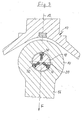
- FIG 3 one recognizes a catch mouth generally designated 10
- Trailer coupling which is rotatably mounted about an axis 12 on a towing vehicle can be.
- the jaw 10 takes a drawbar eye 14 of a pull rod 16 a not shown on trailer.
- the drawbar eye 14 is of a Coupling pin 18 passes through, with a game 20 between the outer periphery the coupling pin 18 and the inner circumference of the drawbar eye 14 is made.
- a Damping device formed, which will be explained in more detail below.
- the coupling pin 18 In a crowned region 22 of the coupling pin 18, which is in operation within the drawbar eye 14 is located, the coupling pin 18 has three radial stepped holes 24th with a larger diameter outer portion 26 and a smaller inside section 28.
- the holes 24 are in uniform angular intervals of 120 ° over the circumference of the Coupling pin 18 distributed.
- a damping piston 30 In each stepped bore 24 is a damping piston 30 slidably guided, the one lying in the bore portion 26 Piston head 32 and a lying in the bore portion 28 piston shaft 34th Has.
- Each stepped bore 24 is at its radially inner end with a axially parallel bore 36 in conjunction, extending over the entire length of the Coupling pin 18 extends and at its the free end of the Coupling pin 18 corresponding lower end by a Closure stopper 38 is closed.
- the coupling pin 18 has at its upper end, i. at the bolt head one smaller diameter section 40, on which a Aufwerfring 42 to the Bolt axis is rotatably mounted.
- This lifting ring 42 is above it radially projecting pin 44 (Figure 2) in engagement with Aufwerfhebeln, the part of the Actuating mechanism of the hitch are, as shown by the Figures 7 to 13 will be explained later in more detail.
- the raising ring 42 is through a stop ring 46 held in its axial position, in turn, by a locking ring 48 is held on the coupling pin 18.
- Of the Stop ring 46 has a serving as a fluid reservoir 50 for a damping fluid Cavity at its top by a flat master piston 52nd is closed.
- the structure of the damping device will now be based on the Figures 4 to 6 are explained in more detail, which encircled in the figure 1 Show detail in an enlarged view in different working positions.
- the so tightly sealed fluid reservoir 50 communicates with the three paraxial Bores 36, of which only one is shown in FIGS. 1 to 6, each via a generally designated 58 pressure compensation valve in Connection.
- This includes a control piston 60, in a bore 36th coaxial but against this larger diameter bore 62 axially slidably guided.
- the control piston 60 is located on an O-ring 64 on the achsnormalen bore bottom 66 on.
- the control piston 60 is replaced by a in the Bore 62 screwed nut 68 stretched against the bore bottom 66, between the nut 68 and the achsnormalen surface facing the mother Regulating piston 60 another O-ring 70 is located.
- the control piston 60 has a central passageway 72 which is the top and the bottom of the control piston 60 connects to each other. At his Bottom of the passageway 72 is expanded to a conical valve seat 74, in by means of a spring 76, a valve ball 78 is pressed.
- the spring 76 is in a spring housing used in an extension of the axial bore 36 80, which has a passage 82, so that fluid through the Spring housing 80 can flow.
- the valve seat 74 and the valve ball 78 together with the spring 76 form a check valve.
- a first plunger 84 is inserted, the one opposite the inner diameter of the passage channel 72 smaller outer diameter Has.
- This first plunger 84 is acted upon by a further plunger 86, the the nut 68 passes through and one over the upper end of the coupling pin 18th protruding plunger head 88 has, on which a pressure plate 90 rests.
- the Pressure plate 90 is common to the three plungers 86. She can over three with uniform angular intervals over the circumference of the coupling pin distributed linkage 92 are axially adjusted.
- Each of these poles consists of a first pin 94 which is in an axially parallel bore 96 in the Stop ring 46 is slidably guided and down from the stop ring Protrudes 46, wherein the bore 96 is sealed by a ring seal 98.
- the first bolt 94 cooperates with a second bolt 100, which in a substantially radially directed recess 102 of the stop ring 46th is arranged and projects inwardly into the fluid reservoir 50, where he with its inner end rests on an edge 104 of the pressure plate 90.
- the master piston 52 is replaced by a tension or safety lever in the Fluid reservoir 50 is pressed, as later with reference to the figures 7 to 13 is explained. Thereby, a certain pressure in the fluid reservoir 50 be maintained.
- FIG. 4 shows the damping device with the clutch closed.
- the pressure compensation valve 58 separates the area between the pressure compensating valve 58 and the damping piston 30 of the Fluid reservoir 50.
- the control piston 60 is floating between the Bore bottom 66 and the bottom of the nut 68 stored.
- the O-rings 64 and 70 biased.
- a further adjusting nut 110 screwed with an axial distance or clearance between the Plunger 84 and the valve ball 78 can be adjusted.
- FIG. 3 which is a concentric Arrangement of drawbar eye 14 and coupling pin 18 shows, in all three Damping piston 30 abut the Switzerlandöseninnen context, one by the arrow F characterized force of the drawbar eye 14 on the coupling pin 18th be exercised.
- the towing eye tries to keep the front damping piston 30 in Press the coupling pin, which is in the radial bore 24 and the axially parallel bore 36 builds up a fluid pressure on the valve ball 78th and the control piston 60 and acts on the latter via the master piston 52.
- the floating bearing of the control piston is this together with the Valve ball 78 with increasing pressure from its neutral shown in Figure 4 Position shifted upward until the ball 78, the first plunger 84th touched.
- the ball valve 78 can not continue from this moment on rise above, as this is prevented by the fixed adjusting nut 110.
- the pressure plate 90 pushes the second plungers 86 and the first Plunger 84 also down, whereby the valve balls 78 of the Check valves are lifted from the valve seats 74, as shown in FIG. 6 shows. As a result, the pressure in the holes 24 and 36 are reduced, so that the damping piston 30 can dodge radially inward. Leave it Open the clutch with reasonable effort.
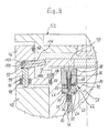
- Figure 7 shows the hitch in the engaged state, i. in the lower position of the coupling pin 18.
- Securing lever 118 on which the actuating mechanism of the clutch to be housed housing 120 of the hitch about an axis 122nd is pivotally mounted, radially into the travel of the coupling pin 18 in, being with a groove 124 via a peripheral upper edge 126 of the Master piston 52 engages and with its front end 128 on the master piston 52 rests.
- This safety lever 118 prevents unwanted Upward movement of the coupling pin 18, since the edge 126 of the Master piston 52 in the groove 124 of the safety lever 118 is spanned.
- a toggle 130 is provided with a first lever 134 hinged to the housing 120 about an axis 132 and a second lever 136, on the one hand with the first lever 134 via a Knee joint 138 is connected and on the other hand in a joint 140 with the Secured lever 118 is connected.
- On the knee joint 138 engages on the one hand by Above a spring 142, which is supported on the housing 120 and the Kniegelenk 138 pushed into the extended position shown in Figure 7.
- a relatively low spring force is sufficient.
- Figure 14 shows hinted the way how the inventive Damping device can also be installed in a fifth wheel.
- the Fifth wheel includes a to be connected to a towing vehicle Clutch plate 148 with a pin receptacle 150 for one with a Trailer to be connected kingpin or kingpins 152th Die Spigot receptacle 150 has a tapered insertion portion 154 and a semi-circular bearing portion 155 in which the kingpin in coupled state is located.
- This bearing portion 155 is of a Horseshoe-shaped wear ring 156 surrounded.
- the kingpin 152 is in at Known way of a coupling hook 158 held around a Axis 160 is pivotally mounted on the saddle plate 148 and by a wedge 162 via an unillustrated actuating linkage in the illustrated Coupling position can be locked.
- a fifth wheel is in itself known and therefore need not be described in detail.
Landscapes
- Engineering & Computer Science (AREA)
- Transportation (AREA)
- Mechanical Engineering (AREA)
- Chemical & Material Sciences (AREA)
- Combustion & Propulsion (AREA)
- Hydraulic Clutches, Magnetic Clutches, Fluid Clutches, And Fluid Joints (AREA)
- Handcart (AREA)
- Control Of Driving Devices And Active Controlling Of Vehicle (AREA)
- Vibration Prevention Devices (AREA)
Abstract
Description
- Figur 1
- einen Axialschnitt durch einen Kupplungsbolzen einer erfindungsgemäßen Anhängekupplung entlang Linie I-I in Figur 2,
- Figur 2
- eine Draufsicht auf den erfindungsgemäßen Kupplungsbolzen,
- Figur 3
- einen Schnitt durch eine erfindungsgemäße Anhängekupplung in der durch die Linie III-III in Figur 1 bezeichnete Schnittebene im gekuppelten Zustand,
- Figur 4
- eine vergrößerte Darstellung des in Figur 1 durch einen Kreis gekennzeichneten Ausschnittes mit dem Druckausgleichsventil in einer ersten Stellung,
- Figur 5
- eine der Figur 4 entsprechende Darstellung mit dem Druckausgleichsventil in einer zweiten Stellung,
- Figur 6
- eine der Figur 4 entsprechende Darstellung mit dem Druckausgleichventil in einer dritten Stellung,
- Figur 7
- einen teilweise schematischen Teilschnitt durch eine erfindungsgemäße Anhängekupplung mit dem Kupplungsbolzen in seiner Schließstellung,
- Figur 8
- eine schematische Teilseitenansicht der in Figur 7 dargestellten Anordnung,
- Figur 9
- eine der Figur 7 entsprechende Darstellung zu Beginn der Öffnung der Kupplung,
- Figur 10
- eine der Figur 8 entsprechende zugehörige Seitenansicht,
- Figur 11
- eine der Figur 7 entsprechende Darstellung mit dem Kupplungsbolzen in seiner Öffnungsstellung,
- Figur 12
- eine der Figur 8 entsprechende zugehörige Seitenansicht,
- Figur 13
- eine schematische Teilrückansicht der in Figur 11 dargestellten Anordnung und
- Figur 14
- eine teilweise geschnittene Draufsicht auf eine Sattelkupplung die mit einer erfindungsgemäßen Dämpfungsvorrichtung versehen ist.
Claims (23)
- Kupplungsanordnung zur Verbindung eines Zugfahrzeugs mit einem Anhänger, umfassend ein zugfahrzeugseitiges Kupplungsteil und ein anhängerseitiges Kupplungsteil, die im gekuppelten Zustand mit Spiel ineinander greifen, dadurch gekennzeichnet, daß in dem zugfahrzeugseitigen Kupplungsteil (18; 156) eine Fluid-Dämpfungsvorrichtung zum Dämpfen der Relativbewegung zwischen den ineinander greifenden Kupplungsteilen (18, 14; 156, 152) angeordnet ist.
- Kupplungsanordnung nach Anspruch 1, dadurch gekennzeichnet, daß das zugfahrzeugseitige Kupplungsteil (18) mindestens einen in einer Kolbenaufnahme (24) verschiebbaren Dämpfungskolben (30) hat, der im gekoppelten Zustand von dem anhängerseitigen Kupplungsteil (14) beaufschlagbar ist, daß die Kolbenaufnahme (24) durch einen Kanal mit einem Fluidreservoir (50) verbunden ist, daß Mittel (118) zum Vorgeben eines Druckes in dem Fluidreservoir (50) vorgesehen sind und daß in dem Kanal (36) ein Druckausgleichsventil (58) angeordnet ist, das beim Überschreiten einer vorgegebenen Druckdifferenz zwischen der Kolbenaufnahme (24) und dem Fluidreservoir (50) öffnet.
- Kupplungsanordnung nach Anspruch 2, dadurch gekennzeichnet, daß die Mittel zum Vorgeben des Fluiddruckes in dem Fluidreservoir (50) einen Geberkolben (52) umfassen, der eine Wand des Fluidreservoirs bildet und auf seiner Außenseite durch ein Spannelement (118) beaufschlagbar ist.
- Kupplungsanordnung nach Anspruch 2 oder 3, dadurch gekennzeichnet, daß das Druckausgleichsventil (58) einen in eine Schließstellung vorgespannten Regelkolben (62) hat, der durch einen Überdruck in der Kolbenaufnahme (24) in Richtung auf eine Öffnungsstellung verstellbar ist.
- Kupplungsanordnung nach Anspruch 4, dadurch gekennzeichnet, daß der Stellweg des Regelkolbens (62) zwischen seiner Schließstellung und seiner Öffnungsstellung einstellbar ist.
- Kupplungsanordnung nach Anspruch 4 oder 5, dadurch gekennzeichnet, daß der Überdruckwert, bei dem der Regelkolben (62) seine Öffnungsstellung erreicht, einstellbar ist.
- Kupplungsanordnung nach einem der Ansprüche 2 bis 6, dadurch gekennzeichnet, daß das Druckausgleichsventil (58) ein Rückschlagventil enthält, das einen Fluidstrom von dem Fluidreservoir (50) zu der Kolbenaufnahme (24) ermöglicht, wenn der Fluiddruck in dem Fluidreservoir (50) höher ist als in der Kolbenaufnahme (24).
- Kupplungsanordnung nach Anspruch 7, dadurch gekennzeichnet, daß das Rückschlagventil unabhängig von dem Druck des Fluides durch eine Stellvorrichtung (84, 86, 88, 90, 92) aufsteuerbar ist.
- Kupplungsanordnung nach Anspruch 8, dadurch gekennzeichnet, daß der Regelkolben (60) einen Durchtrittskanal (72) mit einem Ventilsitz (74) auf seiner der Kolbenaufnahme (24) zugewandten Seite hat, daß an dem Ventilsitz (74) ein Ventilkörper (78) unter Federdruck anliegt und daß die Stellvorrichtung (84, 86, 88, 90, 92) zum Abheben des Ventilkörpers (78) von dem Ventilsitz (74) ausgebildet ist.
- Kupplungsanordnung nach Anspruch 9, dadurch gekennzeichnet, daß die Stellvorrichtung einen Stößel (84, 86) hat, der den Durchtrittskanal (72) in dem Regelkolben (60) mit radialem Spiel durchsetzt und zur Anlage an dem Ventilkörper (78) bestimmt ist, wenn der Regelkolben (60) seine Öffnungsstellung erreicht.
- Kupplungsanordnung nach Anspruch 10, dadurch gekennzeichnet, daß der axiale Abstand, den der Stößel (84) von dem Ventilkörper (78) in der Schließstellung des Regelkörpers (60) hat, einstellbar ist.
- Kupplungsanordnung nach einem der Ansprüche 8 bis 11, dadurch gekennzeichnet, daß die Stellvorrichtung mit einem Betätigungsmechanismus (42, 44, 112, 116) der Kupplung so gekoppelt ist, daß beim Einleiten der Öffnungsbewegung der Kupplungsanordnung das Rückschlagventil (74, 76, 78) aufgesteuert wird.
- Kupplungsanordnung nach einem der Ansprüche 3 bis 12, dadurch gekennzeichnet, daß das den Geberkolben (52) beaufschlagende Spannelement (118) mit dem Betätigungsmechanismus (42, 44, 112, 116) der Kupplungsanordnung so gekoppelt ist, daß der Geberkolben (52) beim Einleiten der Öffnungsbewegung der Kupplungsanordnung entlastet wird.
- Kupplungsanordnung nach einem der Ansprüche 1 bis 13, dadurch gekennzeichnet, daß sie als Anhängekupplung ausgebildet ist mit einem Fangmaul (10) zur Aufnahme einer Zugöse (14) an der Zugstange (16) eines Anhängers, mit einem Kupplungsbolzen (18) und mit einem Betätigungsmechanismus (42, 44, 112, 116) zum Verstellen des Kupplungsbolzens (18) zwischen einer Schließstellung, in der er das Fangmaul (10) und die Zugöse (14) durchsetzt, und einer Öffnungsstellung, in der er aus dem Fangmaul (10) ausgerückt ist, wobei die Dämpfungsvorrichtung in dem Kupplungsbolzen (18) ausgebildet ist.
- Kupplungsanordnung nach Anspruch 14, dadurch gekennzeichnet, daß das Fluidreservoir (50) an dem dem Fangmaul (10) fernen Bolzenkopf des Kupplungsbolzens (18) angeordnet ist, daß die Kolbenaufnahme für den Dämpfungskolben (30) von einer Radialbohrung (24) in dem Kupplungsbolzen (18) gebildet ist und daß der diese Radialbohrung (24) mit dem Fluidreservoir (50) verbindenden Kanal (36) eine achsparallele Bohrung in dem Kupplungsbolzen (18) ist.
- Kupplungsanordnung nach Anspruch 15, dadurch gekennzeichnet, daß der Kupplungsbolzen (18) drei Radialbohrungen (24) mit drei Dämpfungskolben (30) hat, die in gleichförmigen Winkelabständen über den Umfang des Kupplungsbolzens (18) verteilt angeordnet sind und über drei Kanäle (36) und Druckausgleichsventile (58) unabhängig voneinander mit dem Fluidreservoir (50) verbunden sind.
- Kupplungsanordnung nach einem der Ansprüche 14 bis 16, dadurch gekennzeichnet, daß auf dem Kupplungsbolzen (18) nahe dem Bolzenkopf ein Aufwerfring (42) gelagert ist, der mindestens einen radial nach außen abstehenden Fortsatz (44) trägt, an dem ein Aufwerfhebel (112) angreift, der mit einem Handhebel (116) des Betätigungsmechanismus in drehmomentübertragender Verbindung steht.
- Kupplungsanordnung nach Anspruch 17 und Anspruch 8, dadurch gekennzeichnet, daß der Aufwerfhebel (42) zu Beginn seiner Stellbewegung im Sinne eines Öffnens der Kupplung auf die Stellvorrichtung (92) zum Aufsteuern des Rückschlagventils (74, 78) einwirkt.
- Kupplungsanordnung nach einem der Ansprüche 14 bis 18, dadurch gekennzeichnet, daß das auf den Geberkolben (52) einwirkende Spannelement von einem Sicherungshebel (118) gebildet ist, der bei geschlossener Kupplung derart in den Stellweg des Kupplungsbolzens (18) ragt, daß er eine selbsttätige Bewegung des Kupplungsbolzens (18) in Öffnungsrichtung blockiert, und der durch den Betätigungsmechanismus zu Beginn der Verstellung des Kupplungsbolzens (18) in Öffnungsrichtung entriegelbar ist.
- Kupplungsanordnung nach Anspruch 19, dadurch gekennzeichnet, daß der Sicherungshebel (18) an dem Gehäuse (120) der Kupplung schwenkbar gelagert und an den Geberkolben (52) durch einen Kniehebelmechanismus (130) andrückbar ist, an dessen Kniegelenkachse (138) eine Feder (142) in Andruckrichtung und der Betätigungsmechanismus der Kupplung in Öffnungsrichtung angreift.
- Kupplungsanordnung nach einem der Ansprüche 1 bis 13, dadurch gekennzeichnet, daß sie als Sattelkupplung ausgebildet ist, umfassend eine an dem Zugfahrzeug anzuordnende Sattelplatte (148) mit einer Zapfenaufnahme (150) für einen anhängerseitigen Königszapfen (152) und einen mittels eines Betätigungsmechanismus der Sattelkupplung ver- und entriegelbaren Kupplungshaken (158), der den Königszapfen (152) in der gekoppelten Stellung umgreift, wobei die Dämpfungsvorrichtung in eine um die Zapfenaufnahme (150) begrenzenden sattelplattenfesten Wandabschnitt (156) ausgebildet ist.
- Kupplungsanordnung nach Anspruch 21, dadurch gekennzeichnet, daß die Dämpfungsvorrichtung in einem die Zapfenaufnahme (150) hufeisenförmig umgebenden Verschleißring (156) ausgebildet ist.
- Kupplungsanordnung nach Anspruch 21 oder 22 , dadurch gekennzeichnet, daß die Dämpfungsvorrichtung mindestens zwei Dämpfungskolben (30) hat.
Applications Claiming Priority (2)
| Application Number | Priority Date | Filing Date | Title |
|---|---|---|---|
| DE10331884A DE10331884A1 (de) | 2003-07-14 | 2003-07-14 | Kupplungsanordnung zum Verbinden eines Zugfahrzeugs mit einem Anhänger |
| DE10331884 | 2003-07-14 |
Publications (2)
| Publication Number | Publication Date |
|---|---|
| EP1498292A1 true EP1498292A1 (de) | 2005-01-19 |
| EP1498292B1 EP1498292B1 (de) | 2009-08-12 |
Family
ID=33461921
Family Applications (1)
| Application Number | Title | Priority Date | Filing Date |
|---|---|---|---|
| EP04015000A Expired - Lifetime EP1498292B1 (de) | 2003-07-14 | 2004-06-25 | Kupplungsanordnung zum Verbinden eines Zugfahrzeugs mit einem Anhänger |
Country Status (3)
| Country | Link |
|---|---|
| EP (1) | EP1498292B1 (de) |
| AT (1) | ATE439261T1 (de) |
| DE (2) | DE10331884A1 (de) |
Cited By (1)
| Publication number | Priority date | Publication date | Assignee | Title |
|---|---|---|---|---|
| WO2008135204A1 (de) * | 2007-05-03 | 2008-11-13 | Pintsch Bubenzer Gmbh | Kupplungsvorrichtung |
Citations (6)
| Publication number | Priority date | Publication date | Assignee | Title |
|---|---|---|---|---|
| FR1194652A (fr) * | 1958-04-14 | 1959-11-12 | Dispositif d'attelage de camion remorque | |
| DE1872647U (de) * | 1963-03-14 | 1963-05-22 | Werner John | Anhaenger-kupplung fuer einradanhaenger. |
| FR2256648A6 (en) | 1973-12-27 | 1975-07-25 | Faure Jean Louis | Caravan drawgear for automobile - prevents vert angular displacement of trailer shaft upon braking |
| US4131296A (en) * | 1978-01-09 | 1978-12-26 | Motor Wheel Corporation | Self-damping trailer hitch |
| GB2042449A (en) | 1979-01-02 | 1980-09-24 | Slapvagnskopplingar Ab | Trailer coupling |
| EP0320202A2 (de) | 1987-12-10 | 1989-06-14 | Cristopher Paul Ennis | Gehäuse einer Kugelkupplung |
-
2003
- 2003-07-14 DE DE10331884A patent/DE10331884A1/de not_active Withdrawn
-
2004
- 2004-06-25 DE DE502004009876T patent/DE502004009876D1/de not_active Expired - Lifetime
- 2004-06-25 EP EP04015000A patent/EP1498292B1/de not_active Expired - Lifetime
- 2004-06-25 AT AT04015000T patent/ATE439261T1/de not_active IP Right Cessation
Patent Citations (6)
| Publication number | Priority date | Publication date | Assignee | Title |
|---|---|---|---|---|
| FR1194652A (fr) * | 1958-04-14 | 1959-11-12 | Dispositif d'attelage de camion remorque | |
| DE1872647U (de) * | 1963-03-14 | 1963-05-22 | Werner John | Anhaenger-kupplung fuer einradanhaenger. |
| FR2256648A6 (en) | 1973-12-27 | 1975-07-25 | Faure Jean Louis | Caravan drawgear for automobile - prevents vert angular displacement of trailer shaft upon braking |
| US4131296A (en) * | 1978-01-09 | 1978-12-26 | Motor Wheel Corporation | Self-damping trailer hitch |
| GB2042449A (en) | 1979-01-02 | 1980-09-24 | Slapvagnskopplingar Ab | Trailer coupling |
| EP0320202A2 (de) | 1987-12-10 | 1989-06-14 | Cristopher Paul Ennis | Gehäuse einer Kugelkupplung |
Cited By (2)
| Publication number | Priority date | Publication date | Assignee | Title |
|---|---|---|---|---|
| WO2008135204A1 (de) * | 2007-05-03 | 2008-11-13 | Pintsch Bubenzer Gmbh | Kupplungsvorrichtung |
| US8317216B2 (en) | 2007-05-03 | 2012-11-27 | Pintsch Bubenzer Gmbh | Coupling apparatus |
Also Published As
| Publication number | Publication date |
|---|---|
| EP1498292B1 (de) | 2009-08-12 |
| ATE439261T1 (de) | 2009-08-15 |
| DE502004009876D1 (de) | 2009-09-24 |
| DE10331884A1 (de) | 2005-02-10 |
Similar Documents
| Publication | Publication Date | Title |
|---|---|---|
| DE3000619C2 (de) | ||
| EP0381069B1 (de) | Kupplungsmuffe für hydraulische Leitungsverbindung | |
| EP3481687A1 (de) | Park-löse-ventil für ein anhängefahrzeug | |
| DE112005001473B4 (de) | Entsterrbares Rückschlagventil | |
| EP3744592B1 (de) | Bremszylinder mit einer arretierungsvorrichtung zur mechanischen bremskraftverriegelung | |
| EP1495883B1 (de) | Anhängekupplung | |
| DE60303171T2 (de) | Bremssystem für landwirtschaftliches Fahrzeug | |
| DE2500903A1 (de) | Steuerungssystem fuer eine bremse | |
| DE20116706U1 (de) | Zugkupplung mit Stabilisierungseinrichtung | |
| EP1498292B1 (de) | Kupplungsanordnung zum Verbinden eines Zugfahrzeugs mit einem Anhänger | |
| DE102016108897B4 (de) | Verbindungseinrichtung zum Verbinden eines Zugfahrzeugs mit einem Anhänger | |
| DE102017122840B3 (de) | Aktor mit Druckregler im Zulauf des Druckmittelreservoirs sowie Kupplungsbetätigungsvorrichtung | |
| DE10151382B4 (de) | Anhängevorrichtung | |
| EP0164741B1 (de) | Prioritätsventil | |
| DE3039072A1 (de) | Auch unter druck kuppelbare schnellverschlusskupplung | |
| DE102006011676B4 (de) | Anhängerkupplung mit antreibbarem Aufwerfhebel | |
| WO2019115837A1 (de) | SICHER SCHLIEßENDES BESCHLEUNIGUNGSVENTIL FÜR SELBSTTÄTIGE DRUCKLUFTBREMSEN VON SCHIENENFAHRZEUGEN | |
| DE2436808C2 (de) | Stufenhauptzylinder | |
| DE10236686A1 (de) | Bremszange | |
| WO2018006991A1 (de) | Park-löse-ventil für ein anhängefahrzeug | |
| DE19927753B4 (de) | Spielfreie Anhängekupplung | |
| DE3002322A1 (de) | Lastanpassungsventil | |
| DE102024125651A1 (de) | Aktuatoreinheit sowie Kupplungssystem und Schienenfahrzeugeinheit mit einer solchen Aktuatoreinheit | |
| DE3441048C2 (de) | Bremsventil mit stufenlos veränderbarer Druckübersetzung | |
| DE19960302A1 (de) | Steuerventilanordnung für einen hydraulischen Zylinder |
Legal Events
| Date | Code | Title | Description |
|---|---|---|---|
| PUAI | Public reference made under article 153(3) epc to a published international application that has entered the european phase |
Free format text: ORIGINAL CODE: 0009012 |
|
| AK | Designated contracting states |
Kind code of ref document: A1 Designated state(s): AT BE BG CH CY CZ DE DK EE ES FI FR GB GR HU IE IT LI LU MC NL PL PT RO SE SI SK TR |
|
| AX | Request for extension of the european patent |
Extension state: AL HR LT LV MK |
|
| 17P | Request for examination filed |
Effective date: 20050719 |
|
| AKX | Designation fees paid |
Designated state(s): AT BE BG CH CY CZ DE DK EE ES FI FR GB GR HU IE IT LI LU MC NL PL PT RO SE SI SK TR |
|
| 17Q | First examination report despatched |
Effective date: 20061018 |
|
| 17Q | First examination report despatched |
Effective date: 20061018 |
|
| GRAP | Despatch of communication of intention to grant a patent |
Free format text: ORIGINAL CODE: EPIDOSNIGR1 |
|
| RIC1 | Information provided on ipc code assigned before grant |
Ipc: B62D 53/08 20060101ALI20081203BHEP Ipc: B60D 1/02 20060101AFI20081203BHEP |
|
| GRAS | Grant fee paid |
Free format text: ORIGINAL CODE: EPIDOSNIGR3 |
|
| GRAA | (expected) grant |
Free format text: ORIGINAL CODE: 0009210 |
|
| AK | Designated contracting states |
Kind code of ref document: B1 Designated state(s): AT BE BG CH CY CZ DE DK EE ES FI FR GB GR HU IE IT LI LU MC NL PL PT RO SE SI SK TR |
|
| REG | Reference to a national code |
Ref country code: GB Ref legal event code: FG4D Free format text: NOT ENGLISH |
|
| REG | Reference to a national code |
Ref country code: CH Ref legal event code: EP |
|
| REG | Reference to a national code |
Ref country code: IE Ref legal event code: FG4D |
|
| REF | Corresponds to: |
Ref document number: 502004009876 Country of ref document: DE Date of ref document: 20090924 Kind code of ref document: P |
|
| PG25 | Lapsed in a contracting state [announced via postgrant information from national office to epo] |
Ref country code: FI Free format text: LAPSE BECAUSE OF FAILURE TO SUBMIT A TRANSLATION OF THE DESCRIPTION OR TO PAY THE FEE WITHIN THE PRESCRIBED TIME-LIMIT Effective date: 20090812 Ref country code: ES Free format text: LAPSE BECAUSE OF FAILURE TO SUBMIT A TRANSLATION OF THE DESCRIPTION OR TO PAY THE FEE WITHIN THE PRESCRIBED TIME-LIMIT Effective date: 20091123 Ref country code: SE Free format text: LAPSE BECAUSE OF FAILURE TO SUBMIT A TRANSLATION OF THE DESCRIPTION OR TO PAY THE FEE WITHIN THE PRESCRIBED TIME-LIMIT Effective date: 20090812 |
|
| NLV1 | Nl: lapsed or annulled due to failure to fulfill the requirements of art. 29p and 29m of the patents act | ||
| PG25 | Lapsed in a contracting state [announced via postgrant information from national office to epo] |
Ref country code: SI Free format text: LAPSE BECAUSE OF FAILURE TO SUBMIT A TRANSLATION OF THE DESCRIPTION OR TO PAY THE FEE WITHIN THE PRESCRIBED TIME-LIMIT Effective date: 20090812 Ref country code: NL Free format text: LAPSE BECAUSE OF FAILURE TO SUBMIT A TRANSLATION OF THE DESCRIPTION OR TO PAY THE FEE WITHIN THE PRESCRIBED TIME-LIMIT Effective date: 20090812 Ref country code: PL Free format text: LAPSE BECAUSE OF FAILURE TO SUBMIT A TRANSLATION OF THE DESCRIPTION OR TO PAY THE FEE WITHIN THE PRESCRIBED TIME-LIMIT Effective date: 20090812 |
|
| REG | Reference to a national code |
Ref country code: IE Ref legal event code: FD4D |
|
| PG25 | Lapsed in a contracting state [announced via postgrant information from national office to epo] |
Ref country code: BG Free format text: LAPSE BECAUSE OF FAILURE TO SUBMIT A TRANSLATION OF THE DESCRIPTION OR TO PAY THE FEE WITHIN THE PRESCRIBED TIME-LIMIT Effective date: 20091112 Ref country code: PT Free format text: LAPSE BECAUSE OF FAILURE TO SUBMIT A TRANSLATION OF THE DESCRIPTION OR TO PAY THE FEE WITHIN THE PRESCRIBED TIME-LIMIT Effective date: 20091212 |
|
| PG25 | Lapsed in a contracting state [announced via postgrant information from national office to epo] |
Ref country code: IE Free format text: LAPSE BECAUSE OF FAILURE TO SUBMIT A TRANSLATION OF THE DESCRIPTION OR TO PAY THE FEE WITHIN THE PRESCRIBED TIME-LIMIT Effective date: 20090812 Ref country code: DK Free format text: LAPSE BECAUSE OF FAILURE TO SUBMIT A TRANSLATION OF THE DESCRIPTION OR TO PAY THE FEE WITHIN THE PRESCRIBED TIME-LIMIT Effective date: 20090812 Ref country code: CZ Free format text: LAPSE BECAUSE OF FAILURE TO SUBMIT A TRANSLATION OF THE DESCRIPTION OR TO PAY THE FEE WITHIN THE PRESCRIBED TIME-LIMIT Effective date: 20090812 Ref country code: RO Free format text: LAPSE BECAUSE OF FAILURE TO SUBMIT A TRANSLATION OF THE DESCRIPTION OR TO PAY THE FEE WITHIN THE PRESCRIBED TIME-LIMIT Effective date: 20090812 Ref country code: EE Free format text: LAPSE BECAUSE OF FAILURE TO SUBMIT A TRANSLATION OF THE DESCRIPTION OR TO PAY THE FEE WITHIN THE PRESCRIBED TIME-LIMIT Effective date: 20090812 |
|
| PG25 | Lapsed in a contracting state [announced via postgrant information from national office to epo] |
Ref country code: SK Free format text: LAPSE BECAUSE OF FAILURE TO SUBMIT A TRANSLATION OF THE DESCRIPTION OR TO PAY THE FEE WITHIN THE PRESCRIBED TIME-LIMIT Effective date: 20090812 |
|
| PLBE | No opposition filed within time limit |
Free format text: ORIGINAL CODE: 0009261 |
|
| STAA | Information on the status of an ep patent application or granted ep patent |
Free format text: STATUS: NO OPPOSITION FILED WITHIN TIME LIMIT |
|
| 26N | No opposition filed |
Effective date: 20100517 |
|
| PG25 | Lapsed in a contracting state [announced via postgrant information from national office to epo] |
Ref country code: GR Free format text: LAPSE BECAUSE OF FAILURE TO SUBMIT A TRANSLATION OF THE DESCRIPTION OR TO PAY THE FEE WITHIN THE PRESCRIBED TIME-LIMIT Effective date: 20091113 |
|
| BERE | Be: lapsed |
Owner name: SCHNABL, PETER Effective date: 20100630 |
|
| PG25 | Lapsed in a contracting state [announced via postgrant information from national office to epo] |
Ref country code: MC Free format text: LAPSE BECAUSE OF NON-PAYMENT OF DUE FEES Effective date: 20100630 |
|
| REG | Reference to a national code |
Ref country code: CH Ref legal event code: PL |
|
| GBPC | Gb: european patent ceased through non-payment of renewal fee |
Effective date: 20100625 |
|
| REG | Reference to a national code |
Ref country code: FR Ref legal event code: ST Effective date: 20110228 |
|
| PG25 | Lapsed in a contracting state [announced via postgrant information from national office to epo] |
Ref country code: IT Free format text: LAPSE BECAUSE OF FAILURE TO SUBMIT A TRANSLATION OF THE DESCRIPTION OR TO PAY THE FEE WITHIN THE PRESCRIBED TIME-LIMIT Effective date: 20090812 |
|
| PG25 | Lapsed in a contracting state [announced via postgrant information from national office to epo] |
Ref country code: CH Free format text: LAPSE BECAUSE OF NON-PAYMENT OF DUE FEES Effective date: 20100630 Ref country code: LI Free format text: LAPSE BECAUSE OF NON-PAYMENT OF DUE FEES Effective date: 20100630 |
|
| PG25 | Lapsed in a contracting state [announced via postgrant information from national office to epo] |
Ref country code: FR Free format text: LAPSE BECAUSE OF NON-PAYMENT OF DUE FEES Effective date: 20100630 |
|
| PG25 | Lapsed in a contracting state [announced via postgrant information from national office to epo] |
Ref country code: BE Free format text: LAPSE BECAUSE OF NON-PAYMENT OF DUE FEES Effective date: 20100630 |
|
| PG25 | Lapsed in a contracting state [announced via postgrant information from national office to epo] |
Ref country code: GB Free format text: LAPSE BECAUSE OF NON-PAYMENT OF DUE FEES Effective date: 20100625 |
|
| PG25 | Lapsed in a contracting state [announced via postgrant information from national office to epo] |
Ref country code: AT Free format text: LAPSE BECAUSE OF NON-PAYMENT OF DUE FEES Effective date: 20100625 |
|
| PG25 | Lapsed in a contracting state [announced via postgrant information from national office to epo] |
Ref country code: CY Free format text: LAPSE BECAUSE OF FAILURE TO SUBMIT A TRANSLATION OF THE DESCRIPTION OR TO PAY THE FEE WITHIN THE PRESCRIBED TIME-LIMIT Effective date: 20090812 |
|
| PG25 | Lapsed in a contracting state [announced via postgrant information from national office to epo] |
Ref country code: HU Free format text: LAPSE BECAUSE OF FAILURE TO SUBMIT A TRANSLATION OF THE DESCRIPTION OR TO PAY THE FEE WITHIN THE PRESCRIBED TIME-LIMIT Effective date: 20100213 Ref country code: LU Free format text: LAPSE BECAUSE OF NON-PAYMENT OF DUE FEES Effective date: 20100625 |
|
| PG25 | Lapsed in a contracting state [announced via postgrant information from national office to epo] |
Ref country code: TR Free format text: LAPSE BECAUSE OF FAILURE TO SUBMIT A TRANSLATION OF THE DESCRIPTION OR TO PAY THE FEE WITHIN THE PRESCRIBED TIME-LIMIT Effective date: 20090812 |
|
| PGFP | Annual fee paid to national office [announced via postgrant information from national office to epo] |
Ref country code: DE Payment date: 20140724 Year of fee payment: 11 |
|
| REG | Reference to a national code |
Ref country code: DE Ref legal event code: R082 Ref document number: 502004009876 Country of ref document: DE Representative=s name: SCHAUMBURG & PARTNER PATENTANWAELTE GBR, DE Ref country code: DE Ref legal event code: R082 Ref document number: 502004009876 Country of ref document: DE Representative=s name: SCHAUMBURG & PARTNER PATENTANWAELTE MBB, DE Ref country code: DE Ref legal event code: R082 Ref document number: 502004009876 Country of ref document: DE Representative=s name: SCHAUMBURG UND PARTNER PATENTANWAELTE MBB, DE |
|
| REG | Reference to a national code |
Ref country code: DE Ref legal event code: R119 Ref document number: 502004009876 Country of ref document: DE |
|
| PG25 | Lapsed in a contracting state [announced via postgrant information from national office to epo] |
Ref country code: DE Free format text: LAPSE BECAUSE OF NON-PAYMENT OF DUE FEES Effective date: 20160101 |