EP1498204B1 - Werkzeuganordnung mit einem ersten sowie einem zweiten Betriebsmittelkreislauf - Google Patents
Werkzeuganordnung mit einem ersten sowie einem zweiten Betriebsmittelkreislauf Download PDFInfo
- Publication number
- EP1498204B1 EP1498204B1 EP20040013233 EP04013233A EP1498204B1 EP 1498204 B1 EP1498204 B1 EP 1498204B1 EP 20040013233 EP20040013233 EP 20040013233 EP 04013233 A EP04013233 A EP 04013233A EP 1498204 B1 EP1498204 B1 EP 1498204B1
- Authority
- EP
- European Patent Office
- Prior art keywords
- arrangement according
- operating
- tool arrangement
- tool
- medium
- Prior art date
- Legal status (The legal status is an assumption and is not a legal conclusion. Google has not performed a legal analysis and makes no representation as to the accuracy of the status listed.)
- Expired - Lifetime
Links
- XLYOFNOQVPJJNP-UHFFFAOYSA-N water Substances O XLYOFNOQVPJJNP-UHFFFAOYSA-N 0.000 claims description 26
- 238000007789 sealing Methods 0.000 claims description 16
- 239000012530 fluid Substances 0.000 claims description 8
- 239000007788 liquid Substances 0.000 claims description 7
- 239000008367 deionised water Substances 0.000 claims description 6
- 230000000694 effects Effects 0.000 claims description 4
- 239000010720 hydraulic oil Substances 0.000 claims description 4
- 229910021641 deionized water Inorganic materials 0.000 description 5
- 238000004891 communication Methods 0.000 description 4
- 238000011109 contamination Methods 0.000 description 3
- 239000000463 material Substances 0.000 description 3
- 239000003921 oil Substances 0.000 description 3
- 230000035515 penetration Effects 0.000 description 3
- 230000005540 biological transmission Effects 0.000 description 2
- 238000004140 cleaning Methods 0.000 description 2
- 238000005260 corrosion Methods 0.000 description 2
- 230000007797 corrosion Effects 0.000 description 2
- 230000001419 dependent effect Effects 0.000 description 2
- 238000010276 construction Methods 0.000 description 1
- 238000011161 development Methods 0.000 description 1
- 230000018109 developmental process Effects 0.000 description 1
- 238000010586 diagram Methods 0.000 description 1
- JEGUKCSWCFPDGT-UHFFFAOYSA-N h2o hydrate Chemical compound O.O JEGUKCSWCFPDGT-UHFFFAOYSA-N 0.000 description 1
- 238000012544 monitoring process Methods 0.000 description 1
- 238000000926 separation method Methods 0.000 description 1
- 238000010008 shearing Methods 0.000 description 1
- 238000009423 ventilation Methods 0.000 description 1
Images

Classifications
-
- F—MECHANICAL ENGINEERING; LIGHTING; HEATING; WEAPONS; BLASTING
- F15—FLUID-PRESSURE ACTUATORS; HYDRAULICS OR PNEUMATICS IN GENERAL
- F15B—SYSTEMS ACTING BY MEANS OF FLUIDS IN GENERAL; FLUID-PRESSURE ACTUATORS, e.g. SERVOMOTORS; DETAILS OF FLUID-PRESSURE SYSTEMS, NOT OTHERWISE PROVIDED FOR
- F15B3/00—Intensifiers or fluid-pressure converters, e.g. pressure exchangers; Conveying pressure from one fluid system to another, without contact between the fluids
-
- B—PERFORMING OPERATIONS; TRANSPORTING
- B23—MACHINE TOOLS; METAL-WORKING NOT OTHERWISE PROVIDED FOR
- B23D—PLANING; SLOTTING; SHEARING; BROACHING; SAWING; FILING; SCRAPING; LIKE OPERATIONS FOR WORKING METAL BY REMOVING MATERIAL, NOT OTHERWISE PROVIDED FOR
- B23D15/00—Shearing machines or shearing devices cutting by blades which move parallel to themselves
- B23D15/12—Shearing machines or shearing devices cutting by blades which move parallel to themselves characterised by drives or gearings therefor
- B23D15/14—Shearing machines or shearing devices cutting by blades which move parallel to themselves characterised by drives or gearings therefor actuated by fluid or gas pressure
-
- B—PERFORMING OPERATIONS; TRANSPORTING
- B23—MACHINE TOOLS; METAL-WORKING NOT OTHERWISE PROVIDED FOR
- B23D—PLANING; SLOTTING; SHEARING; BROACHING; SAWING; FILING; SCRAPING; LIKE OPERATIONS FOR WORKING METAL BY REMOVING MATERIAL, NOT OTHERWISE PROVIDED FOR
- B23D31/00—Shearing machines or shearing devices covered by none or more than one of the groups B23D15/00 - B23D29/00; Combinations of shearing machines
- B23D31/008—Cutting-up scrap
-
- F—MECHANICAL ENGINEERING; LIGHTING; HEATING; WEAPONS; BLASTING
- F15—FLUID-PRESSURE ACTUATORS; HYDRAULICS OR PNEUMATICS IN GENERAL
- F15B—SYSTEMS ACTING BY MEANS OF FLUIDS IN GENERAL; FLUID-PRESSURE ACTUATORS, e.g. SERVOMOTORS; DETAILS OF FLUID-PRESSURE SYSTEMS, NOT OTHERWISE PROVIDED FOR
- F15B21/00—Common features of fluid actuator systems; Fluid-pressure actuator systems or details thereof, not covered by any other group of this subclass
- F15B21/06—Use of special fluids, e.g. liquid metal; Special adaptations of fluid-pressure systems, or control of elements therefor, to the use of such fluids
-
- A—HUMAN NECESSITIES
- A62—LIFE-SAVING; FIRE-FIGHTING
- A62B—DEVICES, APPARATUS OR METHODS FOR LIFE-SAVING
- A62B3/00—Devices or single parts for facilitating escape from buildings or the like, e.g. protection shields, protection screens; Portable devices for preventing smoke penetrating into distinct parts of buildings
- A62B3/005—Rescue tools with forcing action
-
- Y—GENERAL TAGGING OF NEW TECHNOLOGICAL DEVELOPMENTS; GENERAL TAGGING OF CROSS-SECTIONAL TECHNOLOGIES SPANNING OVER SEVERAL SECTIONS OF THE IPC; TECHNICAL SUBJECTS COVERED BY FORMER USPC CROSS-REFERENCE ART COLLECTIONS [XRACs] AND DIGESTS
- Y10—TECHNICAL SUBJECTS COVERED BY FORMER USPC
- Y10T—TECHNICAL SUBJECTS COVERED BY FORMER US CLASSIFICATION
- Y10T83/00—Cutting
- Y10T83/444—Tool engages work during dwell of intermittent workfeed
- Y10T83/4501—Work feed means controlled by means mounted on tool or tool support
- Y10T83/4503—Such means drives the work feed means
- Y10T83/4508—With supplemental work feed means
-
- Y—GENERAL TAGGING OF NEW TECHNOLOGICAL DEVELOPMENTS; GENERAL TAGGING OF CROSS-SECTIONAL TECHNOLOGIES SPANNING OVER SEVERAL SECTIONS OF THE IPC; TECHNICAL SUBJECTS COVERED BY FORMER USPC CROSS-REFERENCE ART COLLECTIONS [XRACs] AND DIGESTS
- Y10—TECHNICAL SUBJECTS COVERED BY FORMER USPC
- Y10T—TECHNICAL SUBJECTS COVERED BY FORMER US CLASSIFICATION
- Y10T83/00—Cutting
- Y10T83/869—Means to drive or to guide tool
- Y10T83/8821—With simple rectilinear reciprocating motion only
- Y10T83/8858—Fluid pressure actuated
-
- Y—GENERAL TAGGING OF NEW TECHNOLOGICAL DEVELOPMENTS; GENERAL TAGGING OF CROSS-SECTIONAL TECHNOLOGIES SPANNING OVER SEVERAL SECTIONS OF THE IPC; TECHNICAL SUBJECTS COVERED BY FORMER USPC CROSS-REFERENCE ART COLLECTIONS [XRACs] AND DIGESTS
- Y10—TECHNICAL SUBJECTS COVERED BY FORMER USPC
- Y10T—TECHNICAL SUBJECTS COVERED BY FORMER US CLASSIFICATION
- Y10T83/00—Cutting
- Y10T83/929—Tool or tool with support
- Y10T83/9411—Cutting couple type
- Y10T83/9447—Shear type
Definitions
- the present invention relates to a tool assembly with a tool unit, for.
- a tool assembly with a tool unit, for.
- a cutting device a spreader, a squeezing or the like, a control and / or switching element, a drive and a first resource cycle.
- Such a tool is z. B. from the DE 692 21 221 T2 shows, wherein the tool comprises a hydraulic cylinder, the lifting rod actuates the actual tool, which is formed of two blades or arms.
- the hydraulic drive is operated in this particular case by means of a compressible fluid.
- the Hydranlikfactkeiten are usually incompressible oils because of the corrosive properties of the water. However, it may be the case that underwater a reduction or processing of various parts must take place. So it is z. As required in nuclear power plants or reactors to crush various parts under water, since the space for the storage of irradiated material is to be kept as small as possible. In the event of a leak in the tool, all the water, in particular deionized water, must be cleaned, which entails high costs.
- Out EP 0 600 336 A2 is a tool assembly with a tool unit discloses, in which a drive in the form of compressed air, a control element and a first and a second resource circuit is provided.
- the second operating medium circuit is in operative connection via a pressure medium converter in the form of a freely moving piston with the first operating medium circuit.
- the GB 2 018 365 A discloses a tool assembly with a pump as drive and tool units, which are reversibly actuated by means of liquid. Furthermore, a first and second resource circuit is provided, which are in operative connection via a pressure medium converter. The print media converter is preceded by a control
- the tool arrangement comprises a pressure medium converter with two cylinders, in each of which a free piston, which separates the two operating means from each other, is reciprocated by a stroke, and for at least one free piston, a piston level indicator is provided.
- a pressure medium converter with two cylinders, in each of which a free piston, which separates the two operating means from each other, is reciprocated by a stroke, and for at least one free piston, a piston level indicator is provided.
- the first resource circuit with the drive, in particular a pump, and the second resource circuit with the tool unit are in communication. In the tool unit, it may be z. B. order a cutting device, a spreader, a hydraulic cylinder (eg for a press) or the like.
- the tool can be used in a medium which corresponds to the operating medium intended for the second operating medium circuit. If a leak occurs in the tool unit, it is not necessary to clean the entire medium in which work is carried out, since the equipment matches the medium.
- the separation of the two resource circuits also has the advantage that no complex sealing measures must be provided on the tool unit, since leakage does not entail contamination of the medium in which work is carried out.
- a piston position indicator is provided for at least one free piston, preferably for each free piston.
- a piston level indicator can be in communication with the respective free piston, in particular with its end face, and project outward from the cylinder, in particular from its end face. The lifting movement of the respective free piston can thus be monitored in a simple manner from the outside.
- the first operating medium circuit can therefore be operated with a first operating medium and the second operating medium circuit with a second operating medium, wherein the first and the second operating means differ from each other. Accordingly, the optimal equipment can be selected for the tool and the drive.
- first and the second operating means are each liquids, with which a hydraulic drive and a large power transmission associated therewith can be carried out.
- the second resource may be water, especially deionized water.
- the tool can be used in nuclear power plants or nuclear reactors, wherein under water processed various parts, eg. B. can be crushed or cut. A leakage in the tool does not lead to contamination of the deionized and therefore there are no time-consuming and costly cleaning work of the deionized.
- the drive or the pump can be operated with a hydraulic fluid or a hydraulic oil.
- this may be a conventional hydraulic medium, for.
- hydraulic oil or HFC fluid act. Mixing of the two liquids can not take place through the interposed pressure medium converter.
- the two cylinders are arranged parallel to each other, whereby a small size of the pressure medium converter is realized.
- the respective free piston may have at least two spaced-apart sealing elements, which prevent penetration of the operating means at the interface between the free piston and cylinder.
- at least one sealing element can be arranged in the respective end region of the free piston in order to avoid penetration of the first and the second operating means from both sides.
- the sealing elements can be arranged so that the sealing element on the side of the first resource circuit does not cover the same path or the same surface as the sealing element on the side of the second resource circuit to prevent mixing of the various liquids.
- more than one sealing element can be provided on each side of the free piston be.
- the respective free piston may have at least one recess which is arranged between the sealing elements. This recess provides a collection space for the resources that penetrate despite the seals.
- the recess is open to the cylinder jacket and thus absorbs the running in the border region between the free piston and cylinder resources.
- the recess may expediently extend over the entire circumference of the free piston, which ensures that all leaks enter the collecting space.
- the recess may be concave in order to avoid voltage peaks during the movement of the free piston.
- the cylinders can each have at least one outlet, so that leakages or so-called drag oil, which penetrates between the free piston and the cylinder wall, can flow outward.
- the outlet is preferably in the range of movement of the free piston. If seals are provided at the respective end regions of the free piston - as described above - the outlet is expediently arranged in the movement region of the free piston between the two seals. Of the Outlet is not only intended to allow leakage or drag oil to drain, but also serve the ventilation of the cylinder interior, so that z. B. in it can evaporate accumulated water.
- the recess may be associated with at least one outlet in the cylinder.
- the outlet ensures that the leaks accumulated in the recess can flow outward.
- the recess is always in communication with the outlet during the reciprocating movement of the free piston, in order to ensure a drainage of the leak at each position of the free piston.
- the drive itself can be operated or controlled via a remote control, which z. B. when using the tool assembly in a nuclear reactor is advantageous.
- the lines between the print medium converter and the drive on the one hand and the print media converter and the tool on the other hand can have a different length as needed. It is of particular advantage that the lines between the print medium converter and the tool can be very long, with the tool to the application area, for. B. under water, while the pressure medium converter and the drive can remain outside the water at the same time.
- the tool assembly described above for activities such.
- crushing, cutting, cleaning or the like under water z.
- Reference numeral 1 denotes the tool assembly in its entirety.
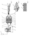
- the tool arrangement 1 comprises a tool unit 2 (at Fig. 2 This is a cutting device 2 '), a drive 3, a control and switching valve 19 and a first resource circuit 4.
- a second resource circuit 5 is provided, which communicates via a pressure medium converter 6 with the first resource circuit 4 in combination.
- FIGS. 3 and 4 tools 2 are shown, which can be connected alternatively to the tool assembly. Accordingly, instead of the cutting device 2 ', either a spreader 2 (FIG. Fig. 3 ) or a hydraulic cylinder 2 '"eg for a press ( Fig. 4 ) be integrated into the tool assembly.
- the first resource circuit 4 communicates with the drive 3, the second resource circuit 5 with the tool unit 2 in connection.
- the first resource circuit 4 is operated with a first resource and the second resource circuit 5 with a second resource, wherein the first and the second resources differ from each other.
- the second operating medium which is directly connected to the tool unit 2 via the second operating medium circuit 5, is water, in particular deionized water, so-called deionate.
- the first resource is hydraulic oil or HFC fluid or the like, and reduces or prevents corrosion and cavitation on the drive 3 side.
- a particularly advantageous application of the tool assembly is the use in nuclear power plants or nuclear reactors to crush the stored in a deionized, irradiated material. This is necessary because the space available for the storage of irradiated material is to be kept as small as possible.
- the pressure medium converter 6 is a separating piston arrangement, the details of which in particular Fig. 2 are clearly visible.
- the pressure medium converter 6 has two cylinders 7, 8, in each of which a free piston 9, 10 is arranged between the two operating medium circuits 4, 5 and the two operating means separated from each other and is reciprocatable by a stroke. This relatively simple construction provides for a direct and with only a few losses associated transmission of hydraulic forces from one to the other resource circuit.
- the two are Cylinders 7, 8 arranged parallel to each other.
- the respective free piston 9, 10 has two spaced-apart sealing elements 11, 12 which are intended to prevent penetration of the liquid operating medium from one to the other operating fluid circuit.
- the sealing elements 11, 12 are each arranged in the end region, ie near the end face of the respective free piston 9, 10.
- the seals 11 do not cover the same area as the seals 12, thus preventing mixing of the different liquids of the two operating medium circuits 4, 5.
- the respective free piston 9, 10 has a recess 13 which is arranged between the sealing elements 11, 12. This recess 13 serves as a reservoir for leaks, ie for the respective operating medium, which penetrates between the free piston 9 or 10 and the cylinder 7 or 8 and the respective sealing element 11, 12.
- the recess 13 extends over the entire circumference of the free piston 9, 10 to reliably absorb all leaks and to make the free piston 9, 10 symmetrical.
- the recess 13 is concave, which has both strength advantages and space advantages.
- outlets 15 are arranged in the respective cylinder 7 or 8 or assigned to the respective recess 13. It is ensured that the recess 13 during the reciprocation of the free piston 9, 10 is in communication with the outlets 15, so that at each position of the free piston 9, 10, a leakage of the leakages is guaranteed. It is of course also possible that the cylinders 7, 8 have only outlets 15 without associated recesses. Also in these cases, the outlet 15 is in the range of movement of the free piston 7,8 and expediently between the two seals 11, 12th
- the pressure medium converter 6 has a piston level indicator 17 on.
- this consists of pins which are connected to the front end of the respective free piston 9,10 and projecting outwardly from the respective cylinder 7, 8 and move along with the free piston 9, 10 accordingly.
- the drive 3 can be actuated or controlled via a remote control 18, which is advantageous in particular when using the tool arrangement in a nuclear power plant or nuclear reactor.
- Reference numeral 20 denotes a safety valve on the hydraulic cylinder 2 '''according to Fig. 4 , Of course, such a safety valve can also be provided with the other tools.
- the lines 20 between the pressure medium converter 6 and the drive 3 on the one hand or the tool unit 2 on the other hand can be of different lengths as needed.
- the lines 20 between the tool unit 2 and the print medium converter 6 are very long, so that the tool unit 2 can be used flexibly under water, at the same time the print medium converter 6 and the drive 3 are positioned outside the water.
Landscapes
- Engineering & Computer Science (AREA)
- Mechanical Engineering (AREA)
- Physics & Mathematics (AREA)
- Fluid Mechanics (AREA)
- General Engineering & Computer Science (AREA)
- Analytical Chemistry (AREA)
- Chemical & Material Sciences (AREA)
- Shearing Machines (AREA)
- Details Of Reciprocating Pumps (AREA)
- Preliminary Treatment Of Fibers (AREA)
- Sealing Devices (AREA)
- Fluid-Pressure Circuits (AREA)
- Radio Relay Systems (AREA)
- Burglar Alarm Systems (AREA)
- Stereo-Broadcasting Methods (AREA)
- Crushing And Grinding (AREA)
- Working Measures On Existing Buildindgs (AREA)
- Crushing And Pulverization Processes (AREA)
Description
- Die vorliegende Erfindung betrifft eine Werkzeuganordnung mit einer Werkzeugeinheit, z. B. einem Schneidegerät, einem Spreizer, einer Quetschvorrichtung oder dergleichen, einem Steuer- und/oder Umschaltelement, einem Antrieb sowie einem ersten Betriebsmittelkreislauf.
- Es sind Werkzeuge wie z. B. Schneidwerkzeuge, Quetschvorrichtungen und dergleichen bekannt, welche große Kräfte übertragen müssen. Solche Werkzeuge sind daher häufig mit einem hydraulischen oder pneumatischen Antrieb ausgestattet, welcher z. B. eine Öffnung- und Schließbewegung eines Spreizers oder einer Schervorrichtung bewirkt.
- Ein derartiges Werkzeug geht z. B. aus der
DE 692 21 221 T2 hervor, wobei das Werkzeug einen hydraulischen Zylinder aufweist, dessen Hubstange das eigentliche Werkzeug betätigt, das aus zwei Schneiden oder Armen gebildet ist. Der hydraulische Antrieb wird in diesem speziellen Fall mittels eines komprimierbaren Fluids betrieben. - Bei den Hydranlikflüssigkeiten handelt es sich meist um inkompressible Öle wegen der korrosiven Eigenschaften des Wassers. Es kann jedoch der Fall auftreten, dass unter Wasser eine Verkleinerung oder Bearbeitung von diversen Teilen stattfinden muss. So ist es z. B. in den Kernkraftwerken oder -reaktoren erforderlich, unter Wasser diverse Teile zu zerkleinern, da der Raum für die Lagerung von verstrahltem Material möglichst klein zu halten ist. Bei einem Leck im Werkzeug muss das gesamte Wasser, bei welchem es sich insbesondere um entionisiertes Wasser (Deionat) handelt, gereinigt werden, was mit hohen Kosten verbunden ist.
- Aus
EP 0 600 336 A2 ist eine Werkzeuganordnung mit einer Werkzeugeinheit offenbart, bei welcher ein Antrieb in Form von Druckluft, ein Steuerelement sowie ein erster und ein zweiter Betriebsmittelkreislauf vorgesehen ist. Der zweite Betriebsmittelkreislauf steht über einem Druckmedienwandler in Form eines sich frei bewegenden Kolbens mit dem ersten Betriebsmittelkreislauf in Wirkverbindung. - Die
GB 2 018 365 A - Es ist die Aufgabe der vorliegenden Erfindung, ein Werkzeug zu schaffen, mit welchem Tätigkeiten unter Wasser durchgeführt werden können, wobei eine gute Überwachung der Tätigkeit von außen möglich ist.
- Diese Aufgabe wird durch die gesamte Lehre des Patentanspruchs 1 gelöst. Vorteilhafte Weiterbildungen der Erfindung ergeben sich aus den Unteransprüchen 2-17. Eine erfindungsgemäße Verwendungsmöglichkeit geht aus Patentanspruch 18 hervor.
- Erfindungsgemäß umfasst die Werkzeuganordnung einen Druckmedienwandler mit zwei Zylindern, in denen jeweils ein Freikolben, der die beiden Betriebsmittel voneinander trennt, um einen Hubweg hin- und herbewegbar ist, und für mindestens einen Freikolben ein Kolbenstandsanzeiger vorgesehen ist. Indem zwei Betriebsmittelkreisläufe bzw. zwei hydraulische oder pneumatische Einheiten vorgesehen sind, können die jeweiligen Betriebsmittelkreisläufe mit einem jeweils unterschiedlichen Betriebsmittel betrieben werden. Diese Aufteilung des Betriebsmittelkreislaufs führt zu vorteilhaften Einsatzmöglichkeiten der Werkzeuganordnung. Mit Vorteil kann der erste Betriebsmittelkreislauf mit dem Antrieb, insbesondere einer Pumpe, und der zweite Betriebsmittelkreislauf mit der Werkzeugeinheit in Verbindung stehen. Bei der Werkzeugeinheit kann es sich z. B. um ein Schneidegerät, einen Spreizer, einen Hydraulikzylinder (z. B. für eine Presse) oder dergleichen handeln. Es ist dadurch mit Vorteil möglich, dass mit dem Werkzeug in einem Medium gearbeitet werden kann, welches dem Betriebsmittel entspricht, das für den zweiten Betriebsmittelkreislauf bestimmt ist. Tritt eine Leckage in der Werkzeugeinheit auf, muss nicht das gesamte Medium, in dem gearbeitet wird, gereinigt werden, da das Betriebsmittel mit dem Medium übereinstimmt. Die Trennung der beiden Betriebsmittelkreisläufe hat außerdem den Vorteil, dass keine aufwändigen Dichtungsmaßnahmen an der Werkzeugeinheit vorgesehen werden müssen, da eine Leckage keine Verunreinigung des Mediums, in dem gearbeitet wird, mit sich bringt.
- Die hydraulische Energie des ersten Betriebsmittelkreislaufes wird mittels des Druckmedienwandler direkt auf den zweiten Betriebsmittelkreislauf übertragen. Um sicherzustellen, dass der jeweilige Freikolben nicht in seine Endlage kommt bzw. der Arbeitshub beobachtet und kontrolliert werden kann, ist für mindestens einen Freikolben, vorzugsweise für jeden Freikolben, ein Kolbenstandsanzeiger vorgesehen. Ein solcher Kolbenstandsanzeiger kann mit dem jeweiligen Freikolben, insbesondere mit dessen Stirnseite, in Verbindung stehen und nach außen aus dem Zylinder, insbesondere aus dessen Stirnseite, herausragen. Die Hubbewegung des jeweiligen Freikolbens kann damit in einfacher Weise von außen überwacht werden.
- Der erste Betriebsmittelkreislauf kann also mit einem ersten Betriebsmittel und der zweite Betriebsmittelkreislauf mit einem zweiten Betriebsmittel betrieben werden, wobei sich das erste und das zweite Betriebsmittel voneinander unterscheiden. Demnach kann für das Werkzeug und dem Antrieb jeweils das optimale Betriebsmittel ausgewählt werden.
- Insbesondere sind das erste und das zweite Betriebsmittel jeweils Flüssigkeiten, mit welchen ein hydraulischer Antrieb und eine damit verbundene große Kraftübertragung durchführbar ist.
- Bei dem zweiten Betriebsmittel kann es sich um Wasser, insbesondere um entionisiertes Wasser (Deionat), handeln. Somit kann das Werkzeug in Kernkraftwerken oder Kernreaktoren eingesetzt werden, wobei unter Wasser diverse Teile bearbeitet, z. B. zerkleinert oder zerschnitten werden können. Eine Leckage im Werkzeug führt nicht zu einer Verunreinigung des Deionates und es fallen demnach auch keine aufwändigen und kostenintensiven Reinigungsarbeitens des Deionates an.
- Da das Betreiben der Pumpe mit Wasser oder Deionat aufgrund der Korrosionseigenschaft des Wassers, der Kavitationsgefahr sowie der Dichtspalte am Kolbenaggregat sehr schwierig ist, kann der Antrieb bzw. die Pumpe mit einer Hydraulikflüssigkeit bzw. einem Hydrauliköl betrieben werden. Insbesondere kann es sich dabei um ein herkömmliches Hydraulikmedium, z. B. Hydrauliköl oder HFC-Fluid, handeln. Eine Vermischung der beiden Flüssigkeiten kann durch den dazwischengeschalteten Druckmedienwandler nicht stattfinden.
- Zweckmäßigerweise sind die beiden Zylinder parallel zueinander angeordnet, womit eine kleine Baugröße des Druckmedienwandlers realisiert wird.
- Um ein Vermischen der beiden Betriebsmittel auszuschließen, kann der jeweilige Freikolben mindestens zwei voneinander beabstandete Dichtelemente aufweisen, die ein Durchdringen des Betriebsmittels an der Grenzfläche zwischen Freikolben und Zylinder verhindern. Zweckmäßigerweise kann mindestens ein Dichtelement im jeweiligen Endbereich des Freikolbens angeordnet sein, um ein Durchdringen des ersten als auch des zweiten Betriebsmittels von beiden Seiten zu vermeiden.
- Mit Vorteil können die Dichtelemente so angeordnet sein, dass das Dichtelement auf der Seite des ersten Betriebsmittelkreislaufes nicht den gleichen Weg bzw. die gleiche Fläche wie das Dichtelement auf der Seite des zweiten Betriebsmittelkreislaufes überstreicht, um ein Vermischen der verschiedenen Flüssigkeiten zu verhindern. Dabei können natürlich auf jeder Seite des Freikolbens mehr als ein Dichtelement vorgesehen sein.
- Ferner kann der jeweilige Freikolben mindestens eine Aussparung aufweisen, die zwischen den Dichtelementen angeordnet ist. Diese Aussparung stellt einen Sammelraum für die Betriebsmittel dar, die trotz der Dichtungen durchdringen.
- Die Aussparung ist zum Zylindermantel hin offen und nimmt so die im Grenzbereich zwischen Freikolben und Zylinder durchtretenden Betriebsmittel auf. Die Aussparung kann sich zweckmäßigerweise über dem gesamten Umfang des Freikolbens erstrecken, womit gewährleistet ist, dass alle Leckagen in den Sammelraum eintreten. Die Aussparung kann konkav ausgebildet sein, um Spannungsspitzen bei der Bewegung des Freikolbens zu vermeiden.
- Die Zylinder können jeweils mindestens einen Auslaß aufweisen, damit Leckagen bzw. sog. Schleppöl, das zwischen Freikolben und Zylinderwand hindurchdringt, nach außen abfließen kann. Demnach befindet sich der Auslaß vorzugsweise im Bewegungsbereich des Freikolbens. Sind an den jeweiligen Endbereichen des Freikolbens Dichtungen vorgesehen - wie oben beschrieben - so ist der Auslaß zweckmäßigerweise im Bewegungsbereich des Freikolbens zwischen den beiden Dichtungen angeordnet. Der Auslaß ist nicht nur dafür vorgesehen, dass Leckagen oder Schleppöl abfließen können, sondern dienen auch der Belüftung des Zylinderinnenraums, so dass z. B. darin angesammeltes Wasser verdunsten kann.
- Mit Vorteil kann der Aussparung mindestens ein Auslaß im Zylinder zugeordnet sein. Der Auslaß sorgt dafür, dass die in der Aussparung angesammelten Leckagen nach außen abfließen können.
- Vorteilhafterweise steht die Aussparung während der Hin- und Herbewegung des Freikolbens mit dem Auslaß stets in Verbindung, um bei jeder Stellung des Freikolbens ein Ablaufen der Leckagen zu gewährleisten.
- Der Antrieb selbst kann über eine Fernbedienung betätigbar bzw. steuerbar sein, was z. B. beim Einsatz der Werkzeuganordnung in einem Kernreaktor von Vorteil ist.
- Die Leitungen zwischen dem Druckmedienwandler und dem Antrieb einerseits sowie dem Druckmedienwandler und dem Werkzeug andererseits können je nach Bedarf eine unterschiedliche Länge haben. Dabei ist es von besonderem Vorteil, dass die Leitungen zwischen dem Druckmedienwandler und dem Werkzeug sehr lang sein können, um mit dem Werkzeug an den Einsatzbereich, z. B. unter Wasser zu gelangen, wobei gleichzeitig der Druckmedienwandler sowie der Antrieb außerhalb des Wassers bleiben können.
- Erfindungsgemäß wird die oben beschriebene Werkzeuganordnung für Tätigkeiten, z. B. Zerkleinerungen, Zerschneidungen, Aufräumarbeiten oder dergleichen unter Wasser, z. B. in einem Kernreaktor, verwendet. So können z. B. Regelstäbe unter Wasser zerkleinert werden, ohne dass eine Verunreinigung des Wassers mit Hydraulikflüssigkeit zu befürchten ist.
- Die Erfindung ist anhand von vorteilhaften Ausführungsbeispielen in den Zeichnungsfiguren näher erläutert. Diese zeigen:
- Fig. 1
- ein Prinzipschaltbild einer Werkzeuganordnung;
- Fig. 2
- eine Schnittdarstellung einer Werkzeuganordnung mit einem Schneidegerät;
- Fig. 3
- eine Schnittdarstellung eines Spreizers sowie
- Fig. 4
- eine Schnittdarstellung eines Hydraulikzylinders.
- Bezugsziffer 1 bezeichnet die Werkzeuganordnung in ihrer Gesamtheit. Die Werkzeuganordnung 1 umfasst eine Werkzeugeinheit 2 (bei
Fig. 2 ist dies ein Schneidegerät 2'), einen Antrieb 3, ein Steuer- und Umschaltventil 19 sowie einen ersten Betriebsmittelkreislauf 4. Außerdem ist ein zweiter Betriebsmittelkreislauf 5 vorgesehen, der über einen Druckmedienwandler 6 mit dem ersten Betriebsmittelkreislauf 4 in Verbindung steht. Insgesamt ergibt damit die Werkzeuganordnung 1 einen geschlossenen Kreis. Die Aufteilung des hydraulischen Kreislaufs in zwei Betriebsmittelkreisläufe führt zu besonders vorteilhaften Anwendungsmöglichkeiten des Werkzeuges 2, welches nicht direkt abhängig von dem Antrieb und dem damit verbundenen Betriebsmittelkreislauf sowie dem dafür benötigten Betriebsmittel ist. - In den
Figuren 3 und 4 sind Werkzeuge 2 dargestellt, die alternativ an die Werkzeuganordnung angeschlossen werden können. Demnach kann statt des Schneidegeräts 2' entweder ein Spreizer 2 (Fig. 3 ) oder ein Hydraulikzylinder 2'" z.B. für eine Presse (Fig. 4 ) in die Werkzeuganordnung integriert sein. - Der erste Betriebsmittelkreislauf 4 steht mit dem Antrieb 3, der zweite Betriebsmittelkreislauf 5 mit der Werkzeugeinheit 2 in Verbindung. Der erste Betriebsmittelkreislauf 4 wird mit einem ersten Betriebsmittel und der zweite Betriebsmittelkreislauf 5 mit einem zweiten Betriebsmittel betrieben, wobei sich das erste und das zweite Betriebsmittel voneinander unterscheiden. Bei dem zweiten Betriebsmittel, welches über den zweiten Betriebsmittelkreislauf 5 direkt mit der Werkzeugeinheit 2 in Verbindung steht, handelt es sich um Wasser, insbesondere entionisiertes Wasser, sog. Deionat. Das erste Betriebsmittel ist Hydrauliköl oder ein HFC-Fluid oder dergleichen und reduziert bzw. verhindert auf der Seite des Antriebs 3 eine Korrosion sowie Kavitation. Indem das Werkzeug bzw. der zweite Betriebsmittelkreislauf 5 nur mit Wasser betrieben wird, kann die Werkzeugeinheit 2 besonders vorteilhaft unter Wasser eingesetzt werden, ohne dass die Gefahr besteht, dass das Medium Wasser bzw. das Deionat durch Leckagen des Betriebsmittels verunreinigt wird.
- Eine besonders vorteilhafte Anwendung der Werkzeuganordnung ist der Einsatz in Kernkraftwerken bzw. Kernreaktoren, um das in einem Deionat gelagerte, verstrahlte Material zu zerkleinern. Dies ist notwendig, da der zur Verfügung stehende Raum für die Lagerung von verstrahltem Material möglichst klein zu halten ist.
- Der Druckmedienwandler 6 ist eine Trennkolbenanordnung, deren Einzelheiten insbesondere in
Fig. 2 deutlich erkennbar sind. Der Druckmedienwandler 6 weist zwei Zylinder 7, 8 auf, in denen jeweils ein Freikolben 9, 10 zwischen den beiden Betriebsmittelkreisläufen 4, 5 angeordnet ist und die beiden Betriebsmittel voneinander trennt und um einen Hubweg hin- und herbewegbar ist. Dieser relativ einfache Aufbau sorgt für eine direkte und mit nur wenigen Verlusten verbundene Übertragung der hydraulischen Kräfte von dem einen auf den anderen Betriebsmittelkreislauf. - Um den Druckmedienwandler 5 möglichst kompakt zu gestalten, sind die beiden Zylinder 7, 8 parallel zueinander angeordnet.
- Der jeweilige Freikolben 9, 10 weist zwei voneinander beabstandete Dichtelemente 11, 12 auf, welche ein Durchdringen des flüssigen Betriebsmittels von dem einen in den anderen Betriebsmittelkreislauf verhindern sollen. Die Dichtelemente 11, 12 sind jeweils im Endbereich, also nahe der Stirnseite des jeweiligen Freikolbens 9, 10 angeordnet. Die Dichtungen 11 überstreichen dabei nicht die gleiche Fläche wie die Dichtungen 12, womit ein Vermischen der unterschiedlichen Flüssigkeiten der beiden Betriebsmittelkreisläufe 4, 5 verhindert wird. Außerdem weist der jeweilige Freikolben 9, 10 eine Aussparung 13 auf, die zwischen den Dichtelementen 11, 12 angeordnet ist. Diese Aussparung 13 dient als Sammelbecken für Leckagen, also für das jeweilige Betriebsmittel, das zwischen dem Freikolben 9 bzw. 10 und dem Zylinder 7 bzw. 8 sowie am jeweiligen Dichtelement 11, 12 hindurchdringt. Die Aussparung 13 erstreckt sich über den gesamten Umfang des Freikolbens 9, 10, um sämtliche Leckagen zuverlässig aufzufangen und um den Freikolben 9, 10 symmetrisch zu gestalten.
- Die Aussparung 13 ist konkav ausgebildet, was sowohl Festigkeitsvorteile als auch Raumvorteile hat.
- Damit die in der Aussparung 13 gesammelten Leckagen abfließen können, sind Auslässe 15 im jeweiligen Zylinder 7 bzw. 8 angeordnet bzw. der jeweiligen Aussparung 13 zugeordnet. Dabei ist sichergestellt, dass die Aussparung 13 während der Hin- und Herbewegung der Freikolben 9, 10 mit den Auslässen 15 in Verbindung steht, so dass bei jeder Stellung der Freikolben 9, 10 ein Abfließen der Leckagen gewährleistet ist. Es ist natürlich auch möglich, dass die Zylinder 7, 8 lediglich Auslässe 15 ohne dazugehörige Aussparungen aufweisen. Auch in diesen Fällen befindet sich der Auslaß 15 im Bewegungsbereich des Freikolbens 7,8 und zweckmäßigerweise zwischen den beiden Dichtungen 11, 12.
- Um die Positionierung bzw. die Endstellung des jeweiligen Freikolbens 9, 10 kontrollieren zu können, weist der Druckmedienwandler 6 einen Kolbenstandsanzeiger 17 auf. Im vorliegenden Beispiel besteht dieser aus Stiften, die mit dem Stirnende des jeweiligen Freikolbens 9,10 verbunden sind und nach außen aus dem jeweiligen Zylinder 7, 8 hervorstehen und sich mit dem Freikolben 9, 10 entsprechend mitbewegen.
- Der Antrieb 3 ist über eine Fernbedienung 18 betätigbar bzw. steuerbar, was insbesondere bei der Verwendung der Werkzeuganordnung in einem Kernkraftwerk bzw. Kernreaktor von Vorteil ist.
- Bezugsziffer 20 bezeichnet ein Sicherheitsventil an dem Hydraulikzylinder 2''' gemäß
Fig. 4 . Ein solches Sicherheitsventil kann natürlich auch bei den anderen Werkzeugen vorgesehen sein. - Die Leitungen 20 zwischen dem Druckmedienwandler 6 und dem Antrieb 3 einerseits bzw. der Werkzeugeinheit 2 andererseits können je nach Bedarf unterschiedlich lang sein. Insbesondere sind die Leitungen 20 zwischen der Werkzeugeinheit 2 und dem Druckmedienwandler 6 sehr lang, damit die Werkzeugeinheit 2 unter Wasser flexibel eingesetzt werden kann, wobei gleichzeitig der Druckmedienwandler 6 und der Antrieb 3 außerhalb des Wassers positioniert sind.
Claims (18)
- Werkzeuganordnung mit einer Werkzeugeinheit (2), z. B. einem Schneidegerät (2'), einem Spreizer (2"), einer Quetschvorrichtung oder dergleichen, einem Antrieb (3), einem Steuer- und/oder Umschaltelement sowie einem ersten Betriebsmittelkreislauf (4), wobei ein zweiter Betriebsmittelkreislauf (5) vorgesehen ist, der über einen Druckmedienwandler (6) mit dem ersten Betriebsmittelkreislauf (7) in Wirkverbindung steht,
dadurch gekennzeichnet, dass
der Druckmedienwandler (6) zwei Zylinder (7, 8) aufweist, in denen jeweils ein Freikolben (9, 10), der die beiden Betriebsmittel voneinander trennt, um einen Hubweg hin- und herbewegbar ist, und für mindestens einen Freikolben (9, 10) ein Kolbenstandsanzeiger (17) vorgesehen ist. - Werkzeuganordnung nach Anspruch 1,
dadurch gekennzeichnet, dass
der erste Betriebsmittelkreislauf (4) mit dem Antrieb (3) und der zweite Betriebsmittelkreislauf (5) mit der Werkzeugeinheit (2) in Verbindung steht. - Werkzeuganordnung nach einem der Ansprüche 1 oder 2,
dadurch gekennzeichnet, dass
der erste Betriebsmittelkreislauf (4) mit einem ersten Betriebsmittel und der zweite Betriebsmittelkreislauf (5) mit einem zweiten Betriebsmittel betrieben wird, wobei sich das erste und das zweite Betriebsmittel voneinander unterscheiden. - Werkzeuganordnung nach Anspruch 3,
dadurch gekennzeichnet, dass
das erste und das zweite Betriebsmittel jeweils Flüssigkeiten sind. - Werkzeuganordnung nach einem der vorhergehenden Ansprüche,
dadurch gekennzeichnet, dass
das zweite Betriebsmittel Wasser, insbesondere entionisiertes Wasser (Deionat) ist. - Werkzeuganordnung nach einem der vorhergehenden Ansprüche,
dadurch gekennzeichnet, dass
das erste Betriebsmittel ein herkömmliches Hydraulikmedium, insbesondere Hydrauliköl oder HFC-Fluid, ist. - Werkzeuganordnung nach einem der vorhergehenden Ansprüche,
dadurch gekennzeichnet, dass
die beiden Zylinder (7, 8) parallel zueinander angeordnet sind. - Werkzeuganordnung nach einem der vorhergehenden Ansprüche,
dadurch gekennzeichnet, dass
der jeweilige Freikolben (9, 10) mindestens zwei voneinander beabstandete Dichtelemente (11, 12) aufweist. - Werkzeuganordnung nach Anspruch 8,
dadurch gekennzeichnet, dass
mindestens ein Dichtelement (11, 12) jeweils im Endbereich des Freikolbens (9 bzw. 10) angeordnet ist. - Werkzeuganordnung nach einem der vorhergehenden Ansprüche,
dadurch gekennzeichnet, dass
die Freikolben (9, 10) jeweils mindestens eine Aussparung (13) aufweisen, die zwischen den Dichtelementen (11, 12) angeordnet ist. - Werkzeuganordnung nach Anspruch 10,
dadurch gekennzeichnet, dass
die Aussparung (13) zum Zylindermantel (14) hin offen ist. - Werkzeuganordnung nach einem der Ansprüche 10 oder 11,
dadurch gekennzeichnet, dass
die Aussparung (13) sich über dem gesamten Umfang des jeweiligen Freikolbens (9, 10) erstreckt. - Werkzeuganordnung nach einem der Ansprüche 10 bis 12,
dadurch gekennzeichnet, dass
die Aussparung (13) konkav ausgebildet ist. - Werkzeuganordnung nach einem der vorhergehenden Ansprüche,
dadurch gekennzeichnet, dass
die Zylinder (7, 8) jeweils mindestens einen Auslaß (15) aufweisen. - Werkzeuganordnung nach einem der Ansprüche 10 bis 14,
dadurch gekennzeichnet, dass
der Aussparung (13) mindestens ein Auslaß (15) im Zylinder (7 bzw. 8) zugeordnet ist. - Werkzeuganordnung nach einem der Ansprüche 10 bis 15,
dadurch gekennzeichnet, dass
die Aussparung (13) während der Hin- und Herbewegung des Freikolbens (9 bzw. 10) mit dem Auslaß (15) in Verbindung steht. - Werkzeuganordnung nach einem der vorhergehenden Ansprüche,
dadurch gekennzeichnet, dass
der Antrieb (3) über eine Fernbedienung (18) betätigbar bzw. steuerbar ist. - Verwendung der Werkzeuganordnung nach einem der vorhergehenden Ansprüche 1 bis 17 für Tätigkeiten, z. B. Zerkleinerungen, Zerschneidungen oder dergleichen unter Wasser, z. B. in einem Kernreaktor.
Applications Claiming Priority (2)
| Application Number | Priority Date | Filing Date | Title |
|---|---|---|---|
| DE10332778 | 2003-07-17 | ||
| DE2003132778 DE10332778B4 (de) | 2003-07-17 | 2003-07-17 | Werkzeuganordnung und Verwendung der Werkzeuganordnung |
Publications (3)
| Publication Number | Publication Date |
|---|---|
| EP1498204A2 EP1498204A2 (de) | 2005-01-19 |
| EP1498204A3 EP1498204A3 (de) | 2005-07-20 |
| EP1498204B1 true EP1498204B1 (de) | 2008-03-12 |
Family
ID=33461997
Family Applications (1)
| Application Number | Title | Priority Date | Filing Date |
|---|---|---|---|
| EP20040013233 Expired - Lifetime EP1498204B1 (de) | 2003-07-17 | 2004-06-04 | Werkzeuganordnung mit einem ersten sowie einem zweiten Betriebsmittelkreislauf |
Country Status (4)
| Country | Link |
|---|---|
| US (1) | US7240490B2 (de) |
| EP (1) | EP1498204B1 (de) |
| AT (1) | ATE388780T1 (de) |
| DE (2) | DE10332778B4 (de) |
Families Citing this family (12)
| Publication number | Priority date | Publication date | Assignee | Title |
|---|---|---|---|---|
| DE102004007684C5 (de) | 2004-02-16 | 2010-01-07 | Minibooster Hydraulics A/S | Tragbares hydraulisches Werkzeug |
| DE102005024039A1 (de) * | 2005-05-25 | 2006-12-07 | Lukas Hydraulik Gmbh | Werkzeugarm aus Verbundmaterial, Verfahren zu seiner Herstellung sowie Werkzeugeinheit |
| US7331109B2 (en) * | 2006-05-12 | 2008-02-19 | Shu-Woan Tu | Electric cutting device |
| US8800343B2 (en) * | 2010-02-15 | 2014-08-12 | Altair Engineering, Inc. | Portable rescue tool and method of use |
| USD664414S1 (en) | 2011-02-14 | 2012-07-31 | Altair Engineering, Inc. | Force arm cutting and prying blade |
| CN102363305A (zh) * | 2011-09-19 | 2012-02-29 | 湘潭市莲城机械有限公司 | 顶拉剪 |
| DE102013105955B4 (de) * | 2013-06-07 | 2018-10-18 | Dionex Softron Gmbh | Vorrichtung zum Bestimmen der Position eines Kolbens einer HPLC-Pumpe |
| US10471618B2 (en) | 2015-12-08 | 2019-11-12 | Milwaukee Electric Tool Corporation | Control of a cutting tool |
| US10507590B2 (en) | 2016-03-14 | 2019-12-17 | Milwaukee Electric Tool Corporation | Control of a cutting tool |
| BR202017017266Y1 (pt) * | 2017-08-11 | 2022-02-01 | Esperanca - Industria Hidraulica Ltda - Epp | Disposição construtiva em equipamento separador de fluidos aplicado em prensa hidráulica |
| IT201800005458A1 (it) * | 2018-05-17 | 2019-11-17 | Sistema per l’esplorazione di tensione in cavi elettrici | |
| CN112122703B (zh) * | 2020-09-22 | 2021-08-24 | 中国船舶科学研究中心 | 一种压力自适应高转速轻型水下切割工具 |
Family Cites Families (9)
| Publication number | Priority date | Publication date | Assignee | Title |
|---|---|---|---|---|
| US3837076A (en) * | 1972-09-14 | 1974-09-24 | L Good | Power operated portable shear device |
| GB2018365B (en) * | 1978-04-05 | 1982-04-21 | Vanesco Ltd | Fluid pressure circuit arrangement |
| GB2093533A (en) * | 1981-02-19 | 1982-09-02 | Brisco Engineering Uk Ltd | Transmitting fluid pressure from one fluid to another for use in a sub-sea well head |
| FR2677908B1 (fr) * | 1991-06-20 | 1995-04-07 | Hydr Am | Outil autonome polyvalent tel que cisaille/ecarteur a commande hydraulique. |
| US5243761A (en) | 1992-03-18 | 1993-09-14 | Hale Fire Pump Company | Portable rescue tool |
| DE4217121C2 (de) | 1992-05-22 | 1996-02-01 | Langenstein & Schemann Gmbh | Freikolben-Zylinder-Vorrichtung mit zwei verschiedenen Druckflüssigkeiten |
| US5265423A (en) * | 1992-12-04 | 1993-11-30 | Power Products Ltd. | Air-oil pressure intensifier with isolation system for prohibiting leakage between and intermixing of the air and oil |
| DE19512367A1 (de) * | 1995-04-01 | 1996-10-02 | Voith Turbo Kg | Antriebseinheit für Förderanlagen, insbesondere Bandantriebsanlage |
| US6250199B1 (en) * | 1999-04-27 | 2001-06-26 | Deep Oil Technology, Incorporated | Subsea power module |
-
2003
- 2003-07-17 DE DE2003132778 patent/DE10332778B4/de not_active Expired - Fee Related
-
2004
- 2004-06-04 EP EP20040013233 patent/EP1498204B1/de not_active Expired - Lifetime
- 2004-06-04 DE DE200450006460 patent/DE502004006460D1/de not_active Expired - Lifetime
- 2004-06-04 AT AT04013233T patent/ATE388780T1/de not_active IP Right Cessation
- 2004-07-15 US US10/892,904 patent/US7240490B2/en not_active Expired - Fee Related
Also Published As
| Publication number | Publication date |
|---|---|
| US7240490B2 (en) | 2007-07-10 |
| ATE388780T1 (de) | 2008-03-15 |
| US20050051014A1 (en) | 2005-03-10 |
| EP1498204A3 (de) | 2005-07-20 |
| DE502004006460D1 (de) | 2008-04-24 |
| DE10332778B4 (de) | 2007-01-25 |
| EP1498204A2 (de) | 2005-01-19 |
| DE10332778A1 (de) | 2005-02-24 |
Similar Documents
| Publication | Publication Date | Title |
|---|---|---|
| DE10332778B4 (de) | Werkzeuganordnung und Verwendung der Werkzeuganordnung | |
| DE69221221T2 (de) | Autonomes Mehrzweckwerkzeug wie Schere/Spreizer mit hydraulischem Antrieb | |
| EP0453773A1 (de) | Abbruchgerät | |
| DE112019001926T5 (de) | Ausgabefilterplattenanordnung für filterpresse | |
| DE69102107T2 (de) | Presse zum Behandeln von Abfällen. | |
| DE112019003791T5 (de) | Fluiddruckgetriebene drucknietvorrichtung | |
| EP0987476A2 (de) | Ventil, insbesondere Doppelsitzventil | |
| DE2242204C3 (de) | Druckmittelbeaufschlagter Servomotor | |
| EP2707215B1 (de) | Stempelanordnung für eine presse und presse | |
| DE102007003890B4 (de) | Vorrichtung zum Auspressen ölhaltigen Pressgutes | |
| DE69603359T2 (de) | Ballenpresse für lose materialien und verfahren zu seiner herstellung | |
| DE2510255A1 (de) | Pneumatisch-hydraulische bremsvorrichtung | |
| EP4226050B1 (de) | Hydraulisch betätigbare, als handgerät ausgebildete arbeitsvorrichtung | |
| WO2010084043A1 (de) | Hydraulische antriebsvorrichtung mit zwei druckräumen und verfahren zum betreiben einer hydraulischen antriebsvorrichtung mit zwei druckräumen | |
| DE69622020T2 (de) | Metallblecharbeitsstation | |
| DE2355035A1 (de) | Dichtungs-verfahren und -anordnung | |
| DE4203056C2 (de) | Schweißaggregat, insbesondere für Vielpunktschweißmaschinen | |
| DE10229276A1 (de) | Vorrichtung zur Überlastsicherung in einer Presse | |
| DE69620156T2 (de) | Verfahren zur metallblechbearbeitung in einer metallblecharbeitsstation und diese metallblecharbeitsstation | |
| DE202014004440U1 (de) | Bearbeitungsmodul für eine Bearbeitungseinheit sowie eine diese verwendende Presse | |
| DE3545478A1 (de) | Presswerkzeug | |
| DE102019001384A1 (de) | Präzisionsschlagzylinder | |
| DE202004002221U1 (de) | Multi-Positions-Tandemzylinder für Schweißzangen | |
| DE102014007825B4 (de) | Bearbeitungsmodul für eine Bearbeitungseinheit einer Presse | |
| WO2025061525A1 (de) | Klemmvorrichtung für eine strangpressvorrichtung, strangpressvorrichtung und verwendung einer strangpressvorrichtung |
Legal Events
| Date | Code | Title | Description |
|---|---|---|---|
| PUAI | Public reference made under article 153(3) epc to a published international application that has entered the european phase |
Free format text: ORIGINAL CODE: 0009012 |
|
| AK | Designated contracting states |
Kind code of ref document: A2 Designated state(s): AT BE BG CH CY CZ DE DK EE ES FI FR GB GR HU IE IT LI LU MC NL PL PT RO SE SI SK TR |
|
| AX | Request for extension of the european patent |
Extension state: AL HR LT LV MK |
|
| PUAL | Search report despatched |
Free format text: ORIGINAL CODE: 0009013 |
|
| AK | Designated contracting states |
Kind code of ref document: A3 Designated state(s): AT BE BG CH CY CZ DE DK EE ES FI FR GB GR HU IE IT LI LU MC NL PL PT RO SE SI SK TR |
|
| AX | Request for extension of the european patent |
Extension state: AL HR LT LV MK |
|
| 17P | Request for examination filed |
Effective date: 20060113 |
|
| AKX | Designation fees paid |
Designated state(s): AT BE BG CH CY CZ DE DK EE ES FI FR GB GR HU IE IT LI LU MC NL PL PT RO SE SI SK TR |
|
| 17Q | First examination report despatched |
Effective date: 20060418 |
|
| GRAP | Despatch of communication of intention to grant a patent |
Free format text: ORIGINAL CODE: EPIDOSNIGR1 |
|
| GRAS | Grant fee paid |
Free format text: ORIGINAL CODE: EPIDOSNIGR3 |
|
| GRAA | (expected) grant |
Free format text: ORIGINAL CODE: 0009210 |
|
| AK | Designated contracting states |
Kind code of ref document: B1 Designated state(s): AT BE BG CH CY CZ DE DK EE ES FI FR GB GR HU IE IT LI LU MC NL PL PT RO SE SI SK TR |
|
| REG | Reference to a national code |
Ref country code: GB Ref legal event code: FG4D Free format text: NOT ENGLISH |
|
| RTI1 | Title (correction) |
Free format text: TOOL ASSEMBLY COMPRISING A FIRST AND A SECOND CIRCUIT FOR THE ACTUATING MEANS |
|
| REG | Reference to a national code |
Ref country code: CH Ref legal event code: EP |
|
| REG | Reference to a national code |
Ref country code: IE Ref legal event code: FG4D Free format text: LANGUAGE OF EP DOCUMENT: GERMAN |
|
| REF | Corresponds to: |
Ref document number: 502004006460 Country of ref document: DE Date of ref document: 20080424 Kind code of ref document: P |
|
| PG25 | Lapsed in a contracting state [announced via postgrant information from national office to epo] |
Ref country code: FI Free format text: LAPSE BECAUSE OF FAILURE TO SUBMIT A TRANSLATION OF THE DESCRIPTION OR TO PAY THE FEE WITHIN THE PRESCRIBED TIME-LIMIT Effective date: 20080312 |
|
| NLV1 | Nl: lapsed or annulled due to failure to fulfill the requirements of art. 29p and 29m of the patents act | ||
| PG25 | Lapsed in a contracting state [announced via postgrant information from national office to epo] |
Ref country code: PL Free format text: LAPSE BECAUSE OF FAILURE TO SUBMIT A TRANSLATION OF THE DESCRIPTION OR TO PAY THE FEE WITHIN THE PRESCRIBED TIME-LIMIT Effective date: 20080312 Ref country code: SI Free format text: LAPSE BECAUSE OF FAILURE TO SUBMIT A TRANSLATION OF THE DESCRIPTION OR TO PAY THE FEE WITHIN THE PRESCRIBED TIME-LIMIT Effective date: 20080312 |
|
| REG | Reference to a national code |
Ref country code: IE Ref legal event code: FD4D |
|
| PG25 | Lapsed in a contracting state [announced via postgrant information from national office to epo] |
Ref country code: CZ Free format text: LAPSE BECAUSE OF FAILURE TO SUBMIT A TRANSLATION OF THE DESCRIPTION OR TO PAY THE FEE WITHIN THE PRESCRIBED TIME-LIMIT Effective date: 20080312 Ref country code: SE Free format text: LAPSE BECAUSE OF FAILURE TO SUBMIT A TRANSLATION OF THE DESCRIPTION OR TO PAY THE FEE WITHIN THE PRESCRIBED TIME-LIMIT Effective date: 20080612 Ref country code: ES Free format text: LAPSE BECAUSE OF FAILURE TO SUBMIT A TRANSLATION OF THE DESCRIPTION OR TO PAY THE FEE WITHIN THE PRESCRIBED TIME-LIMIT Effective date: 20080623 Ref country code: PT Free format text: LAPSE BECAUSE OF FAILURE TO SUBMIT A TRANSLATION OF THE DESCRIPTION OR TO PAY THE FEE WITHIN THE PRESCRIBED TIME-LIMIT Effective date: 20080818 Ref country code: SK Free format text: LAPSE BECAUSE OF FAILURE TO SUBMIT A TRANSLATION OF THE DESCRIPTION OR TO PAY THE FEE WITHIN THE PRESCRIBED TIME-LIMIT Effective date: 20080312 |
|
| PG25 | Lapsed in a contracting state [announced via postgrant information from national office to epo] |
Ref country code: RO Free format text: LAPSE BECAUSE OF FAILURE TO SUBMIT A TRANSLATION OF THE DESCRIPTION OR TO PAY THE FEE WITHIN THE PRESCRIBED TIME-LIMIT Effective date: 20080312 Ref country code: NL Free format text: LAPSE BECAUSE OF FAILURE TO SUBMIT A TRANSLATION OF THE DESCRIPTION OR TO PAY THE FEE WITHIN THE PRESCRIBED TIME-LIMIT Effective date: 20080312 |
|
| BERE | Be: lapsed |
Owner name: LUKAS HYDRAULIK G.M.B.H. Effective date: 20080630 |
|
| EN | Fr: translation not filed | ||
| PLBE | No opposition filed within time limit |
Free format text: ORIGINAL CODE: 0009261 |
|
| STAA | Information on the status of an ep patent application or granted ep patent |
Free format text: STATUS: NO OPPOSITION FILED WITHIN TIME LIMIT |
|
| PG25 | Lapsed in a contracting state [announced via postgrant information from national office to epo] |
Ref country code: MC Free format text: LAPSE BECAUSE OF NON-PAYMENT OF DUE FEES Effective date: 20080630 Ref country code: DK Free format text: LAPSE BECAUSE OF FAILURE TO SUBMIT A TRANSLATION OF THE DESCRIPTION OR TO PAY THE FEE WITHIN THE PRESCRIBED TIME-LIMIT Effective date: 20080312 Ref country code: IE Free format text: LAPSE BECAUSE OF FAILURE TO SUBMIT A TRANSLATION OF THE DESCRIPTION OR TO PAY THE FEE WITHIN THE PRESCRIBED TIME-LIMIT Effective date: 20080312 |
|
| 26N | No opposition filed |
Effective date: 20081215 |
|
| GBPC | Gb: european patent ceased through non-payment of renewal fee |
Effective date: 20080612 |
|
| PG25 | Lapsed in a contracting state [announced via postgrant information from national office to epo] |
Ref country code: BE Free format text: LAPSE BECAUSE OF NON-PAYMENT OF DUE FEES Effective date: 20080630 |
|
| PG25 | Lapsed in a contracting state [announced via postgrant information from national office to epo] |
Ref country code: EE Free format text: LAPSE BECAUSE OF FAILURE TO SUBMIT A TRANSLATION OF THE DESCRIPTION OR TO PAY THE FEE WITHIN THE PRESCRIBED TIME-LIMIT Effective date: 20080312 Ref country code: FR Free format text: LAPSE BECAUSE OF FAILURE TO SUBMIT A TRANSLATION OF THE DESCRIPTION OR TO PAY THE FEE WITHIN THE PRESCRIBED TIME-LIMIT Effective date: 20090102 Ref country code: BG Free format text: LAPSE BECAUSE OF FAILURE TO SUBMIT A TRANSLATION OF THE DESCRIPTION OR TO PAY THE FEE WITHIN THE PRESCRIBED TIME-LIMIT Effective date: 20080612 |
|
| PG25 | Lapsed in a contracting state [announced via postgrant information from national office to epo] |
Ref country code: GB Free format text: LAPSE BECAUSE OF NON-PAYMENT OF DUE FEES Effective date: 20080612 |
|
| PG25 | Lapsed in a contracting state [announced via postgrant information from national office to epo] |
Ref country code: IT Free format text: LAPSE BECAUSE OF FAILURE TO SUBMIT A TRANSLATION OF THE DESCRIPTION OR TO PAY THE FEE WITHIN THE PRESCRIBED TIME-LIMIT Effective date: 20080312 |
|
| PGFP | Annual fee paid to national office [announced via postgrant information from national office to epo] |
Ref country code: AT Payment date: 20090622 Year of fee payment: 6 |
|
| PG25 | Lapsed in a contracting state [announced via postgrant information from national office to epo] |
Ref country code: CY Free format text: LAPSE BECAUSE OF FAILURE TO SUBMIT A TRANSLATION OF THE DESCRIPTION OR TO PAY THE FEE WITHIN THE PRESCRIBED TIME-LIMIT Effective date: 20080312 |
|
| PGFP | Annual fee paid to national office [announced via postgrant information from national office to epo] |
Ref country code: CH Payment date: 20090624 Year of fee payment: 6 |
|
| PG25 | Lapsed in a contracting state [announced via postgrant information from national office to epo] |
Ref country code: LU Free format text: LAPSE BECAUSE OF NON-PAYMENT OF DUE FEES Effective date: 20080604 Ref country code: HU Free format text: LAPSE BECAUSE OF FAILURE TO SUBMIT A TRANSLATION OF THE DESCRIPTION OR TO PAY THE FEE WITHIN THE PRESCRIBED TIME-LIMIT Effective date: 20080913 |
|
| PG25 | Lapsed in a contracting state [announced via postgrant information from national office to epo] |
Ref country code: TR Free format text: LAPSE BECAUSE OF FAILURE TO SUBMIT A TRANSLATION OF THE DESCRIPTION OR TO PAY THE FEE WITHIN THE PRESCRIBED TIME-LIMIT Effective date: 20080312 |
|
| PG25 | Lapsed in a contracting state [announced via postgrant information from national office to epo] |
Ref country code: GR Free format text: LAPSE BECAUSE OF FAILURE TO SUBMIT A TRANSLATION OF THE DESCRIPTION OR TO PAY THE FEE WITHIN THE PRESCRIBED TIME-LIMIT Effective date: 20080613 |
|
| PGFP | Annual fee paid to national office [announced via postgrant information from national office to epo] |
Ref country code: DE Payment date: 20100607 Year of fee payment: 7 |
|
| REG | Reference to a national code |
Ref country code: CH Ref legal event code: PL |
|
| PG25 | Lapsed in a contracting state [announced via postgrant information from national office to epo] |
Ref country code: CH Free format text: LAPSE BECAUSE OF NON-PAYMENT OF DUE FEES Effective date: 20100630 Ref country code: LI Free format text: LAPSE BECAUSE OF NON-PAYMENT OF DUE FEES Effective date: 20100630 |
|
| PG25 | Lapsed in a contracting state [announced via postgrant information from national office to epo] |
Ref country code: AT Free format text: LAPSE BECAUSE OF NON-PAYMENT OF DUE FEES Effective date: 20100604 |
|
| REG | Reference to a national code |
Ref country code: DE Ref legal event code: R119 Ref document number: 502004006460 Country of ref document: DE Effective date: 20120103 |
|
| PG25 | Lapsed in a contracting state [announced via postgrant information from national office to epo] |
Ref country code: DE Free format text: LAPSE BECAUSE OF NON-PAYMENT OF DUE FEES Effective date: 20120103 |