EP1498179A1 - Ceramics honeycomb structural body and method of manufacturing the structural body - Google Patents
Ceramics honeycomb structural body and method of manufacturing the structural body Download PDFInfo
- Publication number
- EP1498179A1 EP1498179A1 EP03717565A EP03717565A EP1498179A1 EP 1498179 A1 EP1498179 A1 EP 1498179A1 EP 03717565 A EP03717565 A EP 03717565A EP 03717565 A EP03717565 A EP 03717565A EP 1498179 A1 EP1498179 A1 EP 1498179A1
- Authority
- EP
- European Patent Office
- Prior art keywords
- honeycomb structure
- ceramics
- ceramics honeycomb
- end part
- substrate
- Prior art date
- Legal status (The legal status is an assumption and is not a legal conclusion. Google has not performed a legal analysis and makes no representation as to the accuracy of the status listed.)
- Withdrawn
Links
Images

Classifications
-
- B—PERFORMING OPERATIONS; TRANSPORTING
- B01—PHYSICAL OR CHEMICAL PROCESSES OR APPARATUS IN GENERAL
- B01D—SEPARATION
- B01D53/00—Separation of gases or vapours; Recovering vapours of volatile solvents from gases; Chemical or biological purification of waste gases, e.g. engine exhaust gases, smoke, fumes, flue gases, aerosols
- B01D53/34—Chemical or biological purification of waste gases
- B01D53/92—Chemical or biological purification of waste gases of engine exhaust gases
- B01D53/94—Chemical or biological purification of waste gases of engine exhaust gases by catalytic processes
- B01D53/9445—Simultaneously removing carbon monoxide, hydrocarbons or nitrogen oxides making use of three-way catalysts [TWC] or four-way-catalysts [FWC]
- B01D53/9454—Simultaneously removing carbon monoxide, hydrocarbons or nitrogen oxides making use of three-way catalysts [TWC] or four-way-catalysts [FWC] characterised by a specific device
-
- B—PERFORMING OPERATIONS; TRANSPORTING
- B01—PHYSICAL OR CHEMICAL PROCESSES OR APPARATUS IN GENERAL
- B01D—SEPARATION
- B01D53/00—Separation of gases or vapours; Recovering vapours of volatile solvents from gases; Chemical or biological purification of waste gases, e.g. engine exhaust gases, smoke, fumes, flue gases, aerosols
- B01D53/34—Chemical or biological purification of waste gases
- B01D53/74—General processes for purification of waste gases; Apparatus or devices specially adapted therefor
- B01D53/86—Catalytic processes
- B01D53/88—Handling or mounting catalysts
- B01D53/885—Devices in general for catalytic purification of waste gases
-
- B—PERFORMING OPERATIONS; TRANSPORTING
- B01—PHYSICAL OR CHEMICAL PROCESSES OR APPARATUS IN GENERAL
- B01J—CHEMICAL OR PHYSICAL PROCESSES, e.g. CATALYSIS OR COLLOID CHEMISTRY; THEIR RELEVANT APPARATUS
- B01J35/00—Catalysts, in general, characterised by their form or physical properties
- B01J35/50—Catalysts, in general, characterised by their form or physical properties characterised by their shape or configuration
- B01J35/56—Foraminous structures having flow-through passages or channels, e.g. grids or three-dimensional [3D] monoliths
- B01J35/57—Honeycombs
-
- F—MECHANICAL ENGINEERING; LIGHTING; HEATING; WEAPONS; BLASTING
- F01—MACHINES OR ENGINES IN GENERAL; ENGINE PLANTS IN GENERAL; STEAM ENGINES
- F01N—GAS-FLOW SILENCERS OR EXHAUST APPARATUS FOR MACHINES OR ENGINES IN GENERAL; GAS-FLOW SILENCERS OR EXHAUST APPARATUS FOR INTERNAL-COMBUSTION ENGINES
- F01N3/00—Exhaust or silencing apparatus having means for purifying, rendering innocuous, or otherwise treating exhaust
- F01N3/08—Exhaust or silencing apparatus having means for purifying, rendering innocuous, or otherwise treating exhaust for rendering innocuous
- F01N3/10—Exhaust or silencing apparatus having means for purifying, rendering innocuous, or otherwise treating exhaust for rendering innocuous by thermal or catalytic conversion of noxious components of exhaust
- F01N3/24—Exhaust or silencing apparatus having means for purifying, rendering innocuous, or otherwise treating exhaust for rendering innocuous by thermal or catalytic conversion of noxious components of exhaust characterised by constructional aspects of converting apparatus
- F01N3/28—Construction of catalytic reactors
- F01N3/2803—Construction of catalytic reactors characterised by structure, by material or by manufacturing of catalyst support
- F01N3/2825—Ceramics
- F01N3/2828—Ceramic multi-channel monoliths, e.g. honeycombs
-
- F—MECHANICAL ENGINEERING; LIGHTING; HEATING; WEAPONS; BLASTING
- F01—MACHINES OR ENGINES IN GENERAL; ENGINE PLANTS IN GENERAL; STEAM ENGINES
- F01N—GAS-FLOW SILENCERS OR EXHAUST APPARATUS FOR MACHINES OR ENGINES IN GENERAL; GAS-FLOW SILENCERS OR EXHAUST APPARATUS FOR INTERNAL-COMBUSTION ENGINES
- F01N2260/00—Exhaust treating devices having provisions not otherwise provided for
- F01N2260/14—Exhaust treating devices having provisions not otherwise provided for for modifying or adapting flow area or back-pressure
-
- F—MECHANICAL ENGINEERING; LIGHTING; HEATING; WEAPONS; BLASTING
- F01—MACHINES OR ENGINES IN GENERAL; ENGINE PLANTS IN GENERAL; STEAM ENGINES
- F01N—GAS-FLOW SILENCERS OR EXHAUST APPARATUS FOR MACHINES OR ENGINES IN GENERAL; GAS-FLOW SILENCERS OR EXHAUST APPARATUS FOR INTERNAL-COMBUSTION ENGINES
- F01N2260/00—Exhaust treating devices having provisions not otherwise provided for
- F01N2260/18—Exhaust treating devices having provisions not otherwise provided for for improving rigidity, e.g. by wings, ribs
-
- F—MECHANICAL ENGINEERING; LIGHTING; HEATING; WEAPONS; BLASTING
- F01—MACHINES OR ENGINES IN GENERAL; ENGINE PLANTS IN GENERAL; STEAM ENGINES
- F01N—GAS-FLOW SILENCERS OR EXHAUST APPARATUS FOR MACHINES OR ENGINES IN GENERAL; GAS-FLOW SILENCERS OR EXHAUST APPARATUS FOR INTERNAL-COMBUSTION ENGINES
- F01N2330/00—Structure of catalyst support or particle filter
- F01N2330/30—Honeycomb supports characterised by their structural details
- F01N2330/34—Honeycomb supports characterised by their structural details with flow channels of polygonal cross section
-
- Y—GENERAL TAGGING OF NEW TECHNOLOGICAL DEVELOPMENTS; GENERAL TAGGING OF CROSS-SECTIONAL TECHNOLOGIES SPANNING OVER SEVERAL SECTIONS OF THE IPC; TECHNICAL SUBJECTS COVERED BY FORMER USPC CROSS-REFERENCE ART COLLECTIONS [XRACs] AND DIGESTS
- Y02—TECHNOLOGIES OR APPLICATIONS FOR MITIGATION OR ADAPTATION AGAINST CLIMATE CHANGE
- Y02A—TECHNOLOGIES FOR ADAPTATION TO CLIMATE CHANGE
- Y02A50/00—TECHNOLOGIES FOR ADAPTATION TO CLIMATE CHANGE in human health protection, e.g. against extreme weather
- Y02A50/20—Air quality improvement or preservation, e.g. vehicle emission control or emission reduction by using catalytic converters
-
- Y—GENERAL TAGGING OF NEW TECHNOLOGICAL DEVELOPMENTS; GENERAL TAGGING OF CROSS-SECTIONAL TECHNOLOGIES SPANNING OVER SEVERAL SECTIONS OF THE IPC; TECHNICAL SUBJECTS COVERED BY FORMER USPC CROSS-REFERENCE ART COLLECTIONS [XRACs] AND DIGESTS
- Y02—TECHNOLOGIES OR APPLICATIONS FOR MITIGATION OR ADAPTATION AGAINST CLIMATE CHANGE
- Y02T—CLIMATE CHANGE MITIGATION TECHNOLOGIES RELATED TO TRANSPORTATION
- Y02T10/00—Road transport of goods or passengers
- Y02T10/10—Internal combustion engine [ICE] based vehicles
- Y02T10/12—Improving ICE efficiencies
-
- Y—GENERAL TAGGING OF NEW TECHNOLOGICAL DEVELOPMENTS; GENERAL TAGGING OF CROSS-SECTIONAL TECHNOLOGIES SPANNING OVER SEVERAL SECTIONS OF THE IPC; TECHNICAL SUBJECTS COVERED BY FORMER USPC CROSS-REFERENCE ART COLLECTIONS [XRACs] AND DIGESTS
- Y10—TECHNICAL SUBJECTS COVERED BY FORMER USPC
- Y10T—TECHNICAL SUBJECTS COVERED BY FORMER US CLASSIFICATION
- Y10T428/00—Stock material or miscellaneous articles
- Y10T428/24—Structurally defined web or sheet [e.g., overall dimension, etc.]
- Y10T428/24149—Honeycomb-like
Definitions
- the present invention relates to a ceramics honeycomb structure having a porous structure and a method of manufacturing the same. More particularly, it relates to a ceramics honeycomb structure which has an excellent erosion resistance at its honeycomb end face and is well balanced in characteristics such as purification performance and canning properties and has the characteristics suitable, particularly, as carriers for automobile exhaust gas purification catalysts, and further relates to a method of manufacturing the ceramics honeycomb structure.
- Ceramics honeycomb structures widely used for exhaust gas purification catalyst carriers are required to have a higher purification performance for coping with regulations on exhaust gas which have been yearly tightened and are further required to be reduced in pressure loss for reduction of fuel cost and increase of output.
- a substrate having a honeycomb structure mainly composed of a raw material convertible into cordierite is fired, then a slurry prepared by dispersing the a raw material convertible into cordierite in a dispersion medium is applied to partition walls positioned at a cell opening end part of the substrate, and thereafter the substrate is dried and fired (for example, see patent document 1).
- this method requires firing step which needs a long time at two stages, namely, firing of the substrate and firing for providing the partition wall reinforced portion, and thus has serious problems in production efficiency and production cost.
- a method which comprises applying a slurry prepared by dispersing a partition wall reinforcing material in a dispersion medium to partition walls positioned at the cell opening end part at a stage before firing the substrate of honeycomb structure, and then drying and firing the substrate, whereby firing of the substrate and formation of the partition wall reinforced portion are performed by one firing (for example, see patent document 1).
- the substrate before firing usually contains organic binders and the like added for the purpose of improving strength of the partition walls, but no consideration has been given to the fact that most of the organic binders are water-soluble compounds such as methyl cellulose.
- the organic binder dissolves in the slurry to cause distortion of partition walls of the resulting honeycomb structure to cause reduction of isostatic strength, and thus the honeycomb structure cannot be practically used.
- honeycomb structures Furthermore, with progress in thinning of the wall thickness of honeycomb structures as mentioned above, compressive strength (isostatic strength) of honeycomb structures at the time of canning considerably decreases and the honeycomb structures sometimes cannot be practically used.
- the present invention has been made in view of the above problems in the conventional technologies, and the object is to provide a ceramics honeycomb structure which has an excellent erosion resistance in partition walls positioned at a cell opening end part and a high compressive strength (isostatic strength) at the time of canning and is suitable particularly as an automobile exhaust gas purification catalyst carrier, and a method for producing the ceramics honeycomb structure.
- a ceramics honeycomb structure which is formed of a plurality of cells forming a fluid flow passage partitioned by porous partition walls and has an inflow end part allowing fluid to flow therein, an outflow end part allowing fluid to flow therefrom, and an outer peripheral part including an outer peripheral surface as its respective parts, characterized by having such a structure that a porosity per unit volume (cm 3 ) gradually increases from the inflow end part side to the outflow end part side at a rate of 0.2%/mm or less (the first invention) .
- the ceramics honeycomb structure has such a structure that the porosity per unit volume (cm 3 ) gradually increases from the inflow end part side to the outflow end part side at a rate of 0.1%/mm or less.
- a ceramics honeycomb structure which is formed of a plurality of cells forming a fluid flow passage partitioned by porous partition walls and has an inflow end part allowing fluid to flow therein, an outflow end part allowing fluid to flow therefrom, and an outer peripheral part including an outer peripheral surface as its respective parts, characterized by having such a structure that a porosity per unit volume (cm 3 ) gradually decreases from the central part of a section perpendicular to the flow passage of the cells to the outer peripheral part at a rate of 0.2%/mm or less (the second invention).
- the ceramics honeycomb structure has such a structure that the porosity per unit volume (cm 3 ) gradually decreases from the central part of a section perpendicular to the flow passage of the cells to the outer peripheral part at a rate of 0.1%/mm or less.
- a porosity per unit volume (cm 3 ) within the area of up to 150 mm from the flow passage end face of the inflow end part side in the inward direction of the flow passage is 10-50%.
- the minimum thickness of the partition walls is 0.030-0.076 mm
- the ceramics honeycomb structure comprises at least one ceramics selected from the group consisting of cordierite, alumina, mullite, silicon nitride, aluminum titanate, zirconia and silicon carbide.
- the section perpendicular to the flow passage has a shape of circle, ellipse, oval, trapezoid, triangle, tetragon, hexagon or left-right asymmetrical irregular shape, and the section of the cells perpendicular to the flow passage has a shape of triangle, tetragon or hexagon.
- the ceramics honeycomb structure of the present invention is preferably used for automobile exhaust gas purification catalyst carriers, and preferably the ceramics honeycomb structure in which a catalyst component is supported on the partition walls is incorporated into a catalyst converter by being held at the outer peripheral surface of the outer wall.
- a method for producing a ceramics honeycomb structure characterized in that a dried substrate having a honeycomb structure is obtained using a clay mainly composed of a ceramics material, the substrate is coated with and impregnated with a reinforcing agent mainly composed of a compound having in its structure at least one element selected from the group consisting of Si, Ti, Mg and Al, and thereafter the substrate is fired (the third invention).
- a method for producing a ceramics honeycomb structure characterized in that a dried substrate having a honeycomb structure is obtained using a clay mainly composed of a ceramics material, the substrate is fired to obtain a fired substrate, the resulting fired substrate is coated with and impregnated with a reinforcing agent mainly composed of a compound having in its structure at least one element selected from the group consisting of Si, Ti, Mg and Al, and thereafter the substrate is fired again (the fourth invention).
- said compound is preferably one which produces an inorganic oxide upon burning, and more preferably one which has a siloxane bond.
- said compound is preferably a silicone oil, a silicone varnish, an alkoxy oligomer or a mixture thereof.
- the reinforcing agent preferably has an absolute viscosity of 1-10000 mPa ⁇ s.
- the ceramics material is preferably a raw material convertible into cordierite, and the clay preferably contains a water-soluble organic binder.
- This water-soluble organic binder preferably comprises at least one water-soluble compound selected from the group consisting of hydroxypropylmethyl cellulose, methyl cellulose, hydroxyethyl cellulose, carboxymethyl cellulose, polyvinyl alcohol and polyvinyl acetal.
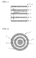
- Fig. 1 is a schematic side view of a ceramics honeycomb structure which shows the parts from which samples are taken (A-E) (hereinafter referred to as sampling parts).
- Fig. 2 is a schematic view of a section perpendicular to the flow passage of cells of a ceramics honeycomb structure which shows the sampling parts (F-J).
- Fig. 3 is a graph in which porosity (%) is plotted against the sampling parts (mm) on the ceramics honeycomb structures produced in examples and comparative examples.
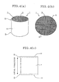
- Fig. 4(a) - Fig. 4(c) schematically show one embodiment of the ceramics honeycomb structure of the present invention (the first invention), and Fig. 4(a) is an oblique view, Fig. 4(b) is a plan view and Fig. 4(c) is a side view.
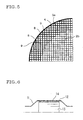
- Fig. 5 is a partially enlarged view which shows another embodiment of the ceramics honeycomb structure of the present invention (the first and second inventions).
- Fig. 6 schematically shows an example in which the ceramics honeycomb structure is incorporated in a converter container.
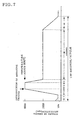
- Fig. 7 is a graph which shows the condition of engine speed in erosion test.
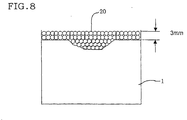
- Fig. 8 schematically shows the method for measurement of erosion amount.
- the ceramics honeycomb structure of the present invention is a ceramics honeycomb structure formed of a plurality of cells forming a fluid flow passage partitioned by porous partition walls and having an inflow end part allowing fluid to flow therein, an outflow end part allowing fluid to flow therefrom, and an outer peripheral part including an outer peripheral surface, characterized by having such a structure that a porosity per unit volume (cm 3 ) gradually increases from the inflow end part side to the outflow end part side at a rate of 0.2%/mm or less.
- a porosity per unit volume cm 3
- Fig. 4 (a) - Fig. 4(c) schematically show one embodiment of the ceramics honeycomb structure of the present invention (the first invention), and Fig. 4(a) is an oblique view, Fig. 4(b) is a plan view and Fig. 4(c) is a side view.
- the ceramics honeycomb structure 1 is formed of a plurality of cells 3 partitioned by porous cell partition walls 2, and has a cell opening end part 5 (an inflow end part) allowing fluid to flow therein, a cell opening end part 5 (an outflow end part) allowing fluid to flow therefrom, and an outer wall 4 as its respective parts.
- the porosity per unit volume (cm 3 ) of the inflow end part side is lower than that of the outflow end part side between the cell opening end parts 5, namely, the inflow end part side has denser microstructure. Therefore, the ceramics honeycomb structure of the present invention has the advantages that problems such as increase of heat capacity and deterioration of catalyst supportability with increase of weight hardly occurs as compared with a ceramics honeycomb structure which is reduced in porosity uniformly through the structure.
- the reference numeral 10 in Fig. 4(c) indicates the opening end part.
- the ceramics honeycomb structure of this embodiment is used as a carrier for exhaust gas purification catalyst by disposing the inflow end part lower in porosity per unit volume (cm 3 ) at the inflow side (upstream side) of the exhaust gas which is a fluid to be treated.
- porosity per unit volume (cm 3 ) at the inflow side (upstream side) of the exhaust gas which is a fluid to be treated.
- the ceramics honeycomb structure of this embodiment that the porosity per unit volume (cm 3 ) gradually increases from the inflow end part side to the outflow end part side at a rate of 0.1%/mm or less.
- One embodiment of the second invention is a ceramics honeycomb structure which is formed of a plurality of cells forming a fluid flow passage partitioned by porous partition walls and has as its respective parts an inflow end part allowing fluid to flow therein, an outflow end part allowing fluid to flow therefrom, and an outer peripheral part including an outer peripheral surface, characterized by having such a structure that a porosity per unit volume (cm 3 ) gradually decreases from the central part of a section perpendicular to the flow passage of the cells towards the outer peripheral part at a rate of 0.2%/mm or less.
- a porosity per unit volume cm 3
- the porosity per unit volume (cm 3 ) of the outer peripheral part is lower than that of the central part, namely, the outer peripheral part has a denser microstructure. Therefore, the ceramics honeycomb structure of the present invention has the advantages that problems such as increase of heat capacity and deterioration of catalyst supportability with increase of weight hardly occur as compared with a ceramics honeycomb structure which is decreased in porosity uniformly through the structure.
- the ceramics honeycomb structure of this embodiment is used by holding (canning) it in a suitable holding container, holding jig, etc.
- the porosity per unit volume (cm 3 ) of the outer peripheral part which contacts with the holding container, jig, etc. is lower than that of the central part, the ceramics honeycomb structure has a sufficient isostatic strength and hence can be surely held in the holding container, holding jig, etc. and problems such as damaging caused by load of compressive face pressure hardly occur.
- isostatic strength here means a strength shown by a pressure value applied at breaking in the test in accordance with automobile standard JASO M505-87.
- the ceramics honeycomb structure of this embodiment that the porosity per unit volume (cm 3 ) gradually decreases from the central part of a section perpendicular to the flow passage of the cells to the outer peripheral part at a rate of 0.1%/mm or less.
- the porosity per unit volume (cm 3 ) in the area of up to 150 mm from the flow passage end face of the inflow end part side in the inward direction of the flow passage is preferably 10-50%, more preferably 15-45%, especially preferably 20-40%.
- the thickness of the partition walls of the ceramics honeycomb structures of the first and second embodiments is not particularly limited, but it is preferably thinner for the improvement of purification performance at the time of warming up by weight-saving and reduction of heat capacity while reducing pressure loss, and specifically it is preferably 0.030-0.076 mm, more preferably 0.030-0.065 mm in minimum partition wall thickness. Furthermore, in the case of the ceramics honeycomb structures of the first and second embodiments, even when the minimum partition wall thickness is less than 0.050 mm, there is substantially no possibility of occurrence of deformation in partition walls.
- the isostatic strength is a strength expressed by a pressure value applied at breaking in the test in accordance with automobile standard JASO M505-87.
- outermost peripheral cells 8 are present closest to the outer wall 4, and the second cells 9 are present inwardly continuing from the outermost peripheral cells 8.
- the thickness of the partition walls of the outermost peripheral cells is shown by Tr 1 and the thickness of the partition walls of the cells 9 positioned inwardly second from the outermost peripheral cells 8 is shown by Tr 2 .
- thickness of partition walls of the 5th to 15th cells are similarly shown by Tr 5-15 .
- the cell partition walls 2 are divided broadly into outer peripheral cell partition walls 2a and basic cell partition walls 2b.
- the outermost peripheral cells when the outermost peripheral cells are called starting point cells, the cells in the range of the 3rd to 20th cells positioned on the inside of the starting point cells are called end point cells, and the cells positioned on the inside of the end point cells are called basic cells, it is preferred that the thickness (Tr 1 , Tr 3-20 ) of the partition walls forming the starting point cells and the end point cells and the thickness (Tc) of the partition walls forming the basic cells satisfy the relation: 1. 10 ⁇ (Tr 1 , Tr 3-20 )/Tc ⁇ 3.00.
- the thickness of the partition walls (Tr 1 , Tr 3-20 ) and the thickness of the basic cells (Tc) have the relation: 1.10 ⁇ (Tr 1 , Tr 3-20 )/Tc ⁇ 2.50, furthermore, 1.20 ⁇ (Tr 1 , Tr 3-20 )/Tc ⁇ 1.60.
- the ceramics honeycomb structures of the embodiments of the first and second inventions comprise, for example, at least one ceramics selected from the group consisting of cordierite, alumina, mullite, silicon nitride, aluminum titanate, zirconia and silicon carbide.
- the section perpendicular to the flow passage of the ceramics honeycomb structures of the embodiments of the first and second inventions has a shape of, for example, circle, ellipse, oval, trapezoid, triangle, tetragon, hexagon or irregular shape asymmetrical in left and right.
- circle, ellipse or oval is preferred.
- the section of the cells perpendicular to the flow passage of the ceramics honeycomb structures of the embodiments of the first and second inventions has a shape of polygon such as triangle, square, rectangle, and hexagon, and preferred is triangle, tetragon or hexagon.
- the ceramics honeycomb structures of the embodiments of the first and second inventions are not particularly limited in their uses, and can be used for various uses such as various filters and catalyst carriers, and especially preferably they are used as carriers for automobile exhaustion gas purification catalysts.
- the ceramics honeycomb structures of the embodiments of the first and second inventions are preferably used by incorporating in a catalyst converter container 11 as shown in Fig. 6.
- the ceramics honeycomb structure 13 is incorporated in the catalyst converter container 11 with its outer peripheral surface being held by a ring 12.
- the material of ring 12 is not particularly limited, and ordinarily a ring made of metallic mesh is used. It is preferred to provide a holding material 14 such as mat or cloth between the catalyst converter container 11 and the outer peripheral surface of the ceramics honeycomb structure 13.
- One embodiment of the third invention is a method for manufacturing the ceramics honeycomb structure having the characteristics as aforementioned, characterized in that a dried substrate having a honeycomb structure before firing is obtained using a clay mainly composed of a ceramics material, the substrate is coated and impregnated with a reinforcing agent mainly composed of a compound having in its structure at least one element selected from the group consisting of Si, Ti, Mg and Al, and thereafter the substrate is fired.
- a dried substrate having a honeycomb structure before firing is obtained using a clay mainly composed of a ceramics material
- the substrate is coated and impregnated with a reinforcing agent mainly composed of a compound having in its structure at least one element selected from the group consisting of Si, Ti, Mg and Al, and thereafter the substrate is fired.
- a reinforcing agent mainly composed of a compound having in its structure an element contributing to gradual increase (gradual decrease) of the porosity of the resulting ceramics honeycomb structure , namely, element contributing to improvement of strength, specifically, at least one element selected from the group consisting of Si, Ti, Mg and A1.
- a method including a step of making the substrate by adding the water-soluble organic binder to the clay is especially preferred, and by this method, there can be produced a ceramics honeycomb structure having no problems such as deformation.
- a reinforcing agent mainly composed of a compound having in its structure an element contributing to improvement of strength the element is uniformly distributed through the whole substrate due to its physicochemical properties. Therefore, a ceramics honeycomb structure uniformly improved in strength can be produced without particular measures such as dispersion, and local occurrence of erosion can be nearly avoided. Furthermore, by using the reinforcing agent as mentioned above, ceramics honeycomb structures having no variation in erosion resistance among products, and excellent in erosion resistance can be stably obtained through simple steps.
- One embodiment of the fourth invention is a method for producing a ceramics honeycomb structure, characterized in that a dried substrate having a honeycomb structure before firing is obtained using a clay mainly composed of a ceramics material, the substrate is fired to obtain a fired substrate, the resulting fired substrate is coated with and impregnated with a reinforcing agent mainly composed of a compound having in its structure at least one element selected from the group consisting of Si, Ti, Mg and Al, and thereafter the substrate is fired again.
- a substrate which is a dried product having a honeycomb structure specifically, a substrate which is a dried product having a honeycomb structure and a plurality of cells forming a fluid flow passage partitioned by partition walls in the form of honeycomb is molded using a clay mainly composed of a ceramics material.
- the ceramics materials are not particularly limited, and there may be used, for example, at least one material selected from the group consisting of silicon carbide, boron carbide, titanium carbide, zirconium carbide, silicon nitride, boron nitride, aluminum nitride, alumina, zirconia, a raw material convertible into cordierite, aluminum titanate and sialon.
- the relation between the kind of the ceramics material and that of the reinforcing material will be mentioned hereinafter.
- the clay may contain other additives.
- water-soluble organic binders include, for example, hydroxypropylmethyl cellulose, methyl cellulose, hydroxyethyl cellulose, carboxymethyl cellulose, polyvinyl alcohol, polyvinyl acetal, etc.
- the crystal growth assistants include, for example, magnesia, silica, yttria, iron oxide, etc.
- the dispersants include, for example, ethylene glycol, dextrin, fatty acid soaps, polyalcohols, etc.
- the pore forming agents include, for example, graphite, wheat flour, starch, phenolic resins, polyethylene terephthalate, etc.
- the clay can be prepared by usual methods, and, for example, it can be obtained by adding additives such as water-soluble organic binder to a ceramics material to prepare a raw material, adding thereto water in a suitable amount, and, if necessary, adding other additives, followed by kneading the mixture by a kneader, a pressure kneader, a vacuum kneader or the like.
- additives such as water-soluble organic binder to a ceramics material to prepare a raw material, adding thereto water in a suitable amount, and, if necessary, adding other additives, followed by kneading the mixture by a kneader, a pressure kneader, a vacuum kneader or the like.
- extrusion molding is preferred from the point of excellent mass-productivity, and it is preferred to carry out the extrusion molding using extrusion molding apparatuses such as ram type extrusion molding apparatus and twin-screw type continuous extrusion molding apparatus.
- the thickness of the partition walls forming cells is also not particularly limited, and, for example, even if the thickness of partition walls is thin, namely, 0.05 mm or less, there can be obtained a ceramics honeycomb structure excellent in physical strengths.
- the substrate which is a dried substrate before firing (unfired substrate) or the fired substrate is coated and impregnated with a given reinforcing agent shown below.
- the similar reinforcing agent can be used at any stages. Therefore, the following explanation is made of a case where a substrate which is a dried substrate before firing is coated and impregnated with the reinforcing agent, but the same can be applied to the case where the fired substrate is coated and impregnated with the reinforcing agent.
- the reinforcing agents there are used those which are mainly composed of a compound having in its structure such an element which reduces the melting point of the ceramics material constituting the substrate or penetrates into pores in the substrate to reduce the volume of the pores, thereby densifying the substrate and contributing to the improvement of strength of the resulting ceramics honeycomb structure.
- a compound having in its structure such an element which reduces the melting point of the ceramics material constituting the substrate or penetrates into pores in the substrate to reduce the volume of the pores, thereby densifying the substrate and contributing to the improvement of strength of the resulting ceramics honeycomb structure.
- Such elements mention may be made of at least one element selected from the group consisting of Si, Ti, Mg and A1.
- the compound which is a main component of the reinforcing agent is preferably one which produces an inorganic oxide upon burning.
- the compounds having Si in the structure are preferably organic compounds having a siloxane bond, and preferred examples thereof are silicone oil, silicone varnish, silicate alkoxy oligomer, mixtures thereof, etc.
- silica (SiO 2 ) can be used, but since silica (SiO 2 ) per se is not liquid, it must be dispersed in a dispersion medium before use.
- silicone oil examples include, for example, dimethyl silicone oil, methylphenyl silicone oil, methyl hydrogen silicone oil, amino-modified silicone oil, epoxy-modified silicone oil, carboxyl-modified silicone oil, carbinol-modified silicone oil, methacryl-modified silicone oil, mercapto-modified silicone oil, phenol-modified silicone oil, one-terminal reactive silicone oil, different-functional groups-modified silicone oil, polyether-modified silicone oil, methylstyryl-modified silicone-oil, alkyl-modified silicone oil, higher fatty acid ester-modified silicone oil, etc.
- aluminate alkoxy oligomers such as acetoalkoxyaluminum diisopropyrate, titanate alkoxy oligomers used as coupling agents, etc.
- magnesia (MgO) as a compound having Mg in the structure, but since magnesia (MgO) per se is not liquid, it must be dispersed in a dispersion medium before use.
- the reinforcing agents can be prepared by using the above compound each alone or in admixture of two or more, and preferably two or more of the compounds are used in admixture.
- the reinforcing agent is prepared by using two or more in admixture, since compounds having various viscosities can be selected and mixed, viscosity of the reinforcing agent can be optionally adjusted and thus it becomes easy to uniformly coat and impregnate the substrate with the resulting reinforcing agent.
- the degree of reinforcement can be controlled with securing the desired thermal shock resistance, and desired erosion resistance can be imparted depending on the thickness of partition walls, etc.
- the mixing ratio (SAO or MHSO/DMSO) of silicate alkoxy oligomer (SAO) or methyl hydrogen silicone oil (MHSO) and dimethyl silicone oil (DMSO) is preferably 10/90-75/25 (mass ratio), more preferably 15/85-50/50 (mass ratio), further preferably 20/80-50/50 (mass ratio), especially preferably 25/75-50/50 (mass ratio).
- the mixing ratio is within the above range, a honeycomb structure excellent in erosion resistance can be obtained with securing the desired thermal shock resistance.
- the reinforcing agents used in the embodiments of the third and fourth inventions may be those which are prepared by diluting the compound such as silicone oil or the like with a diluent containing one or two or more of aromatic hydrocarbons such as toluene and xylene, aliphatic hydrocarbons such as petroleum ethers and kerosene, petroleum hydrocarbons such as kerosene and light oil, alcohols such as isopropyl alcohol, lauryl alcohol and butanol, and volatile silicone oils.
- a diluent containing one or two or more of aromatic hydrocarbons such as toluene and xylene, aliphatic hydrocarbons such as petroleum ethers and kerosene, petroleum hydrocarbons such as kerosene and light oil, alcohols such as isopropyl alcohol, lauryl alcohol and butanol, and volatile silicone oils.
- the reinforcing agents used in the embodiments of the third and fourth inventions have an absolute viscosity of preferably 1-10000 mPa ⁇ s, more preferably 10-1000 mPa ⁇ s.
- the compounds of low viscosity are small in polymerization degree and easily volatilized, and if the viscosity is lower than 1 mPa ⁇ s, when the partition walls are coated and impregnated with the reinforcing agent and fired, generation of CO 2 and evaporation of H 2 O occur, and simultaneously the effective component such as Si present in the reinforcing agent is also volatilized, and as a result it becomes difficult to impart strength.
- the viscosity exceeds 10000 mPa ⁇ s, it becomes difficult to coat and impregnate the substrate with the reinforcing agent at a uniform thickness.
- the compounds which constitute a main component of the reinforcing agents used in the embodiments of the third and fourth inventions it is preferred to select suitable one depending on the kind of the ceramics raw materials.
- a reinforcing agent mainly composed of a compound having Si in the structure specifically a reinforcing agent mainly composed of silicone oil or the like.
- the substrate can be impregnated with the reinforcing agent prepared in the form of liquid or slurry.
- the reinforcing agent prepared in the form of liquid or slurry.
- a sufficient amount of the reinforcing agent is prepared and the whole of the substrate is dipped therein, whereby the substrate is coated and impregnated with the reinforcing agent, and thereafter a compressed air is blown thereinto from the outflow end part side to gradually increase the amount of the reinforcing agent applied to the substrate towards the inflow end part side.
- the reinforcing agent may be coated on the substrate by spray coating, followed by blowing a compressed air thereinto from the outflow end part side to gradually increase the amount of the reinforcing agent applied thereto towards the inflow end part side.
- the substrate can be coated and impregnated with the reinforcing agent, and can be impregnated with the reinforcing agent prepared in the form of liquid or slurry.
- a sufficient amount of the reinforcing agent is prepared and the whole of the substrate is dipped therein, whereby the substrate is coated and impregnated with the reinforcing agent, and then a compressed air or the like is blown thereinto from the inflow end part side or the outflow end part side to remove the reinforcing agent applied in an excess amount by the compressed air and the like.
- the ceramics honeycomb structure can be produced by gradually reducing the pressure of the blown compressed air from the central part of a section perpendicular to the flow passage direction of cells towards the outer peripheral part, reducing the amount of the blown compressed air or shortening the blowing time.
- the ceramics honeycomb structure in which the porosity per unit volume (cm 3 ) gradually decreases from the central part of a section perpendicular to the flow passage direction of cells towards the outer peripheral part can also be produced by a method of stepwise coating and impregnation of the reinforcing agent which is gradually increased in concentration from the central part of a section perpendicular to the flow passage direction of cells towards the outer peripheral part.
- the substrate coated and impregnated with the reinforcing agent is fired.
- the substrate and reinforcing agent are preferably previously dried before firing.
- the drying methods include air-flow drying, hot-air drying, microwave drying, etc.
- the firing conditions are preferably optionally and suitably selected depending on the kinds of substrate and reinforcing agent.
- the substrate is mainly composed of a cordierite-based material and the reinforcing agent is mainly composed of a compound having Si in the structure, such as silicone oil
- the firing may be carried out at 1300-1500°C.
- the firing conditions for coating and impregnating with the reinforcing agent the substrate in the state of fired substrate after firing can be in accordance with conventional methods, and can be optionally selected depending on the kind of the substrate.
- the firing may be carried out at 1300-1500°C.
- the refiring conditions for carrying out refiring after the fired substrate is coated and impregnated with the reinforcing agent can be the firing conditions in the case of coating and impregnating the substrate with the impregnating agent as mentioned above.
- the reinforcing agent is preferably previously dried before refiring, and preferably optional and desired firing conditions are selected depending on the kinds of substrate and reinforcing agent.
- a ceramics honeycomb structure having an excellent erosion resistance of the partition walls positioned in the inflow end part and a high compressive strength (isostatic strength) at the time of canning can be simply produced without resulting in variation in characteristics among products. Furthermore, in this ceramics honeycomb structure, the porosity per unit volume (cm 3 ) gradually increases from the inflow end part side to the outflow end part side or gradually decreases from the central part of a section perpendicular to the flow passage direction of cells towards the outer peripheral part.
- the resulting substrate was wholly dipped in a reinforcing agent shown in Table 1 to coat and impregnate the whole substrate with the reinforcing agent. Then, a compressed air was blown thereinto from the outflow end part side to gradually increase the amount of the coated reinforcing agent towards the inflow end part side, and simultaneously to remove excessively coated reinforcing agent, followed by firing at 1400°C for 4 hours to produce a ceramics honeycomb structure (Examples 1-10).
- a ceramics honeycomb structure was produced in the same manner as in Examples 1-10, except for using a reinforcing agent prepared by adding 0.5 part by mass of a dispersant (polyoxyalkylene-based polymer manufactured by Nippon Oil & Fats Co., Ltd.: MARIALIM AKM-0531) to 100 parts by mass of a dispersion obtained by dispersing 5% by mass of silica (SiO 2 ) powder in kerosene as a dispersion medium (Example 11).
- a dispersant polyoxyalkylene-based polymer manufactured by Nippon Oil & Fats Co., Ltd.: MARIALIM AKM-0531
- a ceramics honeycomb structure was produced in the same manner as in Examples 1-10, except that the substrate having a honeycomb structure (unfired substrate) was fired at 1400°C for 4 hours before wholly dipping in the reinforcing agent and the resulting fired substrate was wholly dipped in the reinforcing agent shown in Table 1 (Example 12).
- a ceramics honeycomb structure was produced in the same manner as in Examples 1-10, except that the amount of the reinforcing agent applied was gradually increased from the central part of a section perpendicular to the flow passage direction of cells towards the outer peripheral part by making a difference in air blow pressure between the inner peripheral part and the outer peripheral part in blowing the compressed air from the flow passage end part side, and the excessively applied reinforcing agent was removed (Example 13).
- a columnar ceramics honeycomb structure was produced in the same manner as in Examples 1-10, except that the substrate was not wholly dipped in the reinforcing agent (no treatment with the reinforcing agent) (Comparative Example 1).
- a columnar ceramics honeycomb structure was produced in the same manner as in Examples 11, except that the substrate having a honeycomb structure (unfired substrate) was dipped in the reinforcing agent up to a depth of 5 mm from the opening end face to coat and impregnate the partition walls positioned in the vicinity of the inflow end part with the reinforcing agent in place of wholly dipping the substrate having a honeycomb structure (unfired substrate) in the reinforcing agent (Comparative Example 2).
- a ceramics honeycomb structure was produced in the same manner as in Comparative Examples 1 (Comparative Example 3).
- a ceramics honeycomb structure was produced in the same manner as in Example 13, except that an extremely large difference in air blow pressure between the inner peripheral part and the outer peripheral part was made in blowing the compressed air from the flow passage end part side, specifically, the air blow pressure was greatly increased with progress from the inner peripheral part to the outer peripheral part (Comparative Example 4).
- Examples 1-13 and Comparative Examples 1-4 The physical properties of the resulting ceramics honeycomb structures (Examples 1-13 and Comparative Examples 1-4) were measured by the following methods and the characteristics were evaluated. The results are shown in Tables 1 and 2.
- the porosity (%) in the sampling part (mm) of the ceramics honeycomb structures of Example 3 and Comparative Examples 1 and 2 is shown in Table 3, and a graph in which porosity (%) is plotted against the sampling parts (mm) is shown in Fig. 3.
- a metal can in which a ceramic honeycomb structure was held and stored was connected to an exhaust port of a gasoline engine of 4 cylinders (in-line) and 1.8 liter in cylinder volume. That is, the sample was disposed close to the engine. Then, the engine was operated under the conditions shown in Fig. 7, and 0.1 g of abrasive grains (silicon carbide, GC320, average particle diameter 50 ⁇ m) were introduced when the number of revolutions reached 6000 rpm. Furthermore, the operation of engine was continued under the conditions shown in Fig. 7, and abrasive grains were introduced once per two cycles (one cycle being 130 seconds) and this was continuously repeated.
- abrasive grains silicon carbide, GC320, average particle diameter 50 ⁇ m
- the erosion amount was determined in the following manner. A rubber sheet was wound round the working end face on the side of measurement of the erosion amount of the ceramics honeycomb structure 1 and ceramics beads 20 having a diameter of 1.5 mm were laid compactly in the structure at a height of about 3 mm. Thereafter, the beads were recovered and the beads volume was measured, and the difference between the beads volume after the erosion test and that before the test was obtained. This was conducted thrice and the average value was taken as the erosion amount.
- a pressure applied at break was measured by conducting the test in accordance with Automobile Standard JASO M505-87, and this pressure was taken as isostatic strength (kg/cm 2 ).
- the ceramics honeycomb structure was heated to a given temperature by an electric furnace, and then taken out and put in an atmosphere of room temperature of 20°C .
- occurrence of defects such as cracks due to thermal shock was visually examined.
- the heating temperature was further raised and the test was repeated up to a temperature at which defects occurred.
- the critical temperature at which occurrence of defects was seen was ascertained, and the thermal shock resistance was evaluated.
- the ceramics honeycomb structures of Examples 1-12 were improved in erosion resistance and isostatic strength as compared with the ceramics honeycomb structure of Comparative Example 1, and were improved in isostatic strength and thermal shock resistance as compared with the ceramics honeycomb structure of Comparative Example 2.
- the reasons for the ceramics honeycomb structures of Examples 1-12 being superior in erosion resistance to the ceramics honeycomb structure of Comparative Example 1 can be considered that the porosity in the inflow end part (A) was lower than that in the outflow end part (E) , and the porosity in the inflow end part (A) was 25% or lower in Examples 1-12 while it was high, namely, 27.5% and low in the part against which the exhaust gas struck in Comparative Example 1.
- the reasons for the ceramics honeycomb structures of Examples 1-12 being superior in isostatic strength to the ceramics honeycomb structures of Comparative Examples 1 and 2 can be considered that the whole of the honeycomb structures showed a tendency of being lower in porosity although it is slight, specifically, the average of the porosity of the whole ceramics honeycomb structures of Examples 1-12 was less than 26% while that of the ceramics honeycomb structures of Comparative Examples 1 and 2 was 26% or higher and besides the proportion of the parts having a porosity of 26% or higher was great. Furthermore, the ceramics honeycomb structures of Examples 1-12 were superior in thermal shock resistance to the ceramics honeycomb structures of Comparative Examples 1 and 2.
- the ceramics honeycomb structure of Example 13 was improved in erosion resistance and isostatic strength as compared with the ceramics honeycomb structure of Comparative Example 3.
- the reason for the ceramics honeycomb structure of Example 13 being superior in erosion resistance to the ceramics honeycomb structure of Comparative Example 3 can be considered that the ceramics honeycomb structure of Example 13 was lower in porosity of the inflow end part as compared with the ceramics honeycomb structure of Comparative Example 3 since the ceramics honeycomb structure of Example 13 was produced by once wholly dipping in the reinforcing agent like the ceramics honeycomb structures of Examples 1-12.
- the reason for the ceramics honeycomb structure of Example 13 being superior in isostatic strength to the ceramics honeycomb structure of Comparative Example 3 can be considered that the porosity of the outer peripheral part (J) was lower than that of the central part (F). Moreover, the ceramics honeycomb structure of Example 13 did not show deterioration of thermal shock resistance as compared with the ceramics honeycomb structure of Comparative Example 3. It is considered that this is because the porosity gently gradually decreases from the central part (F) to the outer peripheral part (J) and hence the generated heat stress and the residual stress at the time of production did not increase.
- Comparative Example 4 when Comparative Example 4 is compared with Example 13, Comparative Example 4 gave erosion resistance and isostatic strength equal to or higher than that of Example 13, but the thermal shock resistance of Comparative Example 3 was extremely inferior. It is considered that this is because the gradual decreasing rate of the porosity per unit volume (cm 3 ) from the central part (F) to the outer peripheral part (J) was greater as compared with Example 13.
- the ceramics honeycomb structure of the present invention has a structure in which a porosity per unit volume (cm 3 ) gradually increases from the inflow end part side to the outflow end part side at a rate lower than a given rate, and hence it has an excellent erosion resistance, isostatic strength and thermal shock resistance.
- a method for producing the ceramics honeycomb structure according to which a substrate (a dried substrate before firing) or a fired substrate having a honeycomb structure obtained using a given clay is coated and impregnated with a given reinforcing agent and then fired (or refired) and this method hardly causes defects such as distortion of partition walls and hardly gives variation in physical properties between the products.
Landscapes
- Chemical & Material Sciences (AREA)
- Engineering & Computer Science (AREA)
- Chemical Kinetics & Catalysis (AREA)
- Environmental & Geological Engineering (AREA)
- Health & Medical Sciences (AREA)
- Oil, Petroleum & Natural Gas (AREA)
- Ceramic Engineering (AREA)
- Biomedical Technology (AREA)
- Analytical Chemistry (AREA)
- General Chemical & Material Sciences (AREA)
- Combustion & Propulsion (AREA)
- Toxicology (AREA)
- Organic Chemistry (AREA)
- Materials Engineering (AREA)
- Mechanical Engineering (AREA)
- General Engineering & Computer Science (AREA)
- Catalysts (AREA)
- Porous Artificial Stone Or Porous Ceramic Products (AREA)
- Devices For Post-Treatments, Processing, Supply, Discharge, And Other Processes (AREA)
- Exhaust Gas After Treatment (AREA)
- Exhaust Gas Treatment By Means Of Catalyst (AREA)
Abstract
The ceramics honeycomb structure of the present
invention is formed of a plurality of cells forming a fluid flow
passage partitioned by porous partition walls, and comprising
an inflow end part allowing fluid to flow therein, an outflow
end part allowing fluid to flow therefrom, and an outer
peripheral part including an outer peripheral surface, and is
characterized by having a structure where a porosity per unit
volume (cm3) gradually increases from the inflow end part side
to the outflow end part side at a rate of 0.2%/mm or less, and
this ceramics honeycomb structure has an excellent erosion
resistance of partition walls positioned at a cell opening end
part and a high compressive strength (isostatic strength) at
the time of canning, and is suitable particularly as an
automobile exhaust gas purification catalyst carrier.
Description
The present invention relates to a ceramics honeycomb
structure having a porous structure and a method of
manufacturing the same. More particularly, it relates to a
ceramics honeycomb structure which has an excellent erosion
resistance at its honeycomb end face and is well balanced in
characteristics such as purification performance and canning
properties and has the characteristics suitable, particularly,
as carriers for automobile exhaust gas purification catalysts,
and further relates to a method of manufacturing the ceramics
honeycomb structure.
Ceramics honeycomb structures widely used for exhaust
gas purification catalyst carriers are required to have a
higher purification performance for coping with regulations on
exhaust gas which have been yearly tightened and are further
required to be reduced in pressure loss for reduction of fuel
cost and increase of output.
Under the circumstances, there are increasing trends to
increase the opening ratio at a cell opening end face of the
honeycomb structures to reduce the pressure loss by thinning
the thickness of partition walls of the honeycomb structures
and to improve purification performance by reducing heat
capacity of partition walls to cause early activation of
catalyst after starting of engine.
On the other hand, with thinning of the partition walls
of honeycomb structures, there is a new problem of occurrence
of such an erosion phenomenon that various foreign matters
incorporated in exhaust gas strike against the partition walls
positioned at a cell opening end part to damage the partition
walls.
For this problem, there has already been proposed a
honeycomb structure in which the partition walls positioned at
the cell opening end part have a partition wall reinforced
portion (reinforced partition wall portion) increased in
strength than other partition wall portions (for example, see
patent document 1), and furthermore various investigations
have been made on the method of providing the reinforced
partition portion.
Hitherto, as a method of providing the partition wall
reinforced portion, it has been known that a substrate having
a honeycomb structure mainly composed of a raw material
convertible into cordierite is fired, then a slurry prepared
by dispersing the a raw material convertible into cordierite
in a dispersion medium is applied to partition walls positioned
at a cell opening end part of the substrate, and thereafter the
substrate is dried and fired (for example, see patent document
1).
However, this method requires firing step which needs a
long time at two stages, namely, firing of the substrate and
firing for providing the partition wall reinforced portion, and
thus has serious problems in production efficiency and
production cost.
On the other hand, a method has been suggested which
comprises applying a slurry prepared by dispersing a partition
wall reinforcing material in a dispersion medium to partition
walls positioned at the cell opening end part at a stage before
firing the substrate of honeycomb structure, and then drying
and firing the substrate, whereby firing of the substrate and
formation of the partition wall reinforced portion are
performed by one firing (for example, see patent document 1).
However, as to this method, no specific investigation is
conducted on the difference in composition before and after the
firing of the substrate. Especially, the substrate before
firing usually contains organic binders and the like added for
the purpose of improving strength of the partition walls, but
no consideration has been given to the fact that most of the
organic binders are water-soluble compounds such as methyl
cellulose.
Therefore, if the step of formation of the partition wall
reinforced portion which has conventionally been carried out
after firing is carried out before firing using a slurry
prepared by dispersing the partition wall reinforcing material
in water, the organic binder dissolves in the slurry to cause
distortion of partition walls of the resulting honeycomb
structure to cause reduction of isostatic strength, and thus
the honeycomb structure cannot be practically used.
Furthermore, in the case of using a slurry prepared by
dispersing a partition wall reinforcing material in a
dispersion medium, the partition wall reinforcing material
settles or agglomerates due to its physical properties, and
dispersibility of the partition wall reinforcing material is
apt to be insufficient. Thus, variation or ununiformity of
reinforcing degree tends to occur in the partition wall
reinforced portion formed. Therefore, this production method
suffers from the problems that a ceramic honeycomb structure
having a uniform erosion resistance in the whole partition wall
reinforced portion cannot be stably obtained, and besides
burden of control for attaining uniform dispersion of the
partition wall reinforcing material increases.
On the other hand, if a slurry prepared by dispersing a
partition wall reinforcing material in a water-insoluble
dispersion medium is used, the problem of reduction in
isostatic strength caused by distortion of partition walls and
others can be solved.
However, even this production method cannot solve the
problems that a ceramic honeycomb structure having a uniform
erosion resistance in the whole partition wall reinforced
portion cannot be stably obtained, and besides burden of
control for attaining uniform dispersion of the partition wall
reinforcing material in the slurry increases.
Furthermore, with progress in thinning of the wall
thickness of honeycomb structures as mentioned above,
compressive strength (isostatic strength) of honeycomb
structures at the time of canning considerably decreases and
the honeycomb structures sometimes cannot be practically used.
The present invention has been made in view of the above
problems in the conventional technologies, and the object is
to provide a ceramics honeycomb structure which has an
excellent erosion resistance in partition walls positioned at
a cell opening end part and a high compressive strength
(isostatic strength) at the time of canning and is suitable
particularly as an automobile exhaust gas purification
catalyst carrier, and a method for producing the ceramics
honeycomb structure.
That is, according to the present invention, there is
provided a ceramics honeycomb structure which is formed of a
plurality of cells forming a fluid flow passage partitioned by
porous partition walls and has an inflow end part allowing fluid
to flow therein, an outflow end part allowing fluid to flow
therefrom, and an outer peripheral part including an outer
peripheral surface as its respective parts, characterized by
having such a structure that a porosity per unit volume (cm3)
gradually increases from the inflow end part side to the outflow
end part side at a rate of 0.2%/mm or less (the first invention) .
In the present invention, it is preferred that the
ceramics honeycomb structure has such a structure that the
porosity per unit volume (cm3) gradually increases from the
inflow end part side to the outflow end part side at a rate of
0.1%/mm or less.
Furthermore, according to the present invention, there
is provided a ceramics honeycomb structure which is formed of
a plurality of cells forming a fluid flow passage partitioned
by porous partition walls and has an inflow end part allowing
fluid to flow therein, an outflow end part allowing fluid to
flow therefrom, and an outer peripheral part including an outer
peripheral surface as its respective parts, characterized by
having such a structure that a porosity per unit volume (cm3)
gradually decreases from the central part of a section
perpendicular to the flow passage of the cells to the outer
peripheral part at a rate of 0.2%/mm or less (the second
invention).
In the present invention, it is preferred that the
ceramics honeycomb structure has such a structure that the
porosity per unit volume (cm3) gradually decreases from the
central part of a section perpendicular to the flow passage of
the cells to the outer peripheral part at a rate of 0.1%/mm or
less.
In the present invention, it is preferred that a porosity
per unit volume (cm3) within the area of up to 150 mm from the
flow passage end face of the inflow end part side in the inward
direction of the flow passage is 10-50%.
In the present invention, it is preferred that the
minimum thickness of the partition walls is 0.030-0.076 mm, and
the ceramics honeycomb structure comprises at least one
ceramics selected from the group consisting of cordierite,
alumina, mullite, silicon nitride, aluminum titanate, zirconia
and silicon carbide.
In the present invention, it is preferred that the
section perpendicular to the flow passage has a shape of circle,
ellipse, oval, trapezoid, triangle, tetragon, hexagon or
left-right asymmetrical irregular shape, and the section of the
cells perpendicular to the flow passage has a shape of triangle,
tetragon or hexagon.
The ceramics honeycomb structure of the present
invention is preferably used for automobile exhaust gas
purification catalyst carriers, and preferably the ceramics
honeycomb structure in which a catalyst component is supported
on the partition walls is incorporated into a catalyst
converter by being held at the outer peripheral surface of the
outer wall.
Further, according to the present invention, there is
provided a method for producing a ceramics honeycomb structure,
characterized in that a dried substrate having a honeycomb
structure is obtained using a clay mainly composed of a ceramics
material, the substrate is coated with and impregnated with a
reinforcing agent mainly composed of a compound having in its
structure at least one element selected from the group
consisting of Si, Ti, Mg and Al, and thereafter the substrate
is fired (the third invention).
Moreover, according to the present invention, there is
provided a method for producing a ceramics honeycomb structure,
characterized in that a dried substrate having a honeycomb
structure is obtained using a clay mainly composed of a ceramics
material, the substrate is fired to obtain a fired substrate,
the resulting fired substrate is coated with and impregnated
with a reinforcing agent mainly composed of a compound having
in its structure at least one element selected from the group
consisting of Si, Ti, Mg and Al, and thereafter the substrate
is fired again (the fourth invention).
In the present invention, said compound is preferably one
which produces an inorganic oxide upon burning, and more
preferably one which has a siloxane bond. In the present
invention, said compound is preferably a silicone oil, a
silicone varnish, an alkoxy oligomer or a mixture thereof. In
the present invention, the reinforcing agent preferably has an
absolute viscosity of 1-10000 mPa·s.
In the present invention, the ceramics material is
preferably a raw material convertible into cordierite, and the
clay preferably contains a water-soluble organic binder. This
water-soluble organic binder preferably comprises at least one
water-soluble compound selected from the group consisting of
hydroxypropylmethyl cellulose, methyl cellulose, hydroxyethyl
cellulose, carboxymethyl cellulose, polyvinyl alcohol and
polyvinyl acetal.
Fig. 1 is a schematic side view of a ceramics honeycomb
structure which shows the parts from which samples are taken
(A-E) (hereinafter referred to as sampling parts).
Fig. 2 is a schematic view of a section perpendicular to
the flow passage of cells of a ceramics honeycomb structure
which shows the sampling parts (F-J).
Fig. 3 is a graph in which porosity (%) is plotted against
the sampling parts (mm) on the ceramics honeycomb structures
produced in examples and comparative examples.
Fig. 4(a) - Fig. 4(c) schematically show one embodiment
of the ceramics honeycomb structure of the present invention
(the first invention), and Fig. 4(a) is an oblique view, Fig.
4(b) is a plan view and Fig. 4(c) is a side view.
Fig. 5 is a partially enlarged view which shows another
embodiment of the ceramics honeycomb structure of the present
invention (the first and second inventions).
Fig. 6 schematically shows an example in which the
ceramics honeycomb structure is incorporated in a converter
container.
Fig. 7 is a graph which shows the condition of engine
speed in erosion test.
Fig. 8 schematically shows the method for measurement of
erosion amount.
The embodiments of the present invention will be
explained below. They should not be construed as limiting the
invention in any manner, and it should be understood that
optional changes, modifications and improvements may be made
based on the normal knowledge of one skilled in the art without
departing from the spirit and scope of the invention.
One embodiment of the ceramics honeycomb structure of the
present invention (the first invention) is a ceramics honeycomb
structure formed of a plurality of cells forming a fluid flow
passage partitioned by porous partition walls and having an
inflow end part allowing fluid to flow therein, an outflow end
part allowing fluid to flow therefrom, and an outer peripheral
part including an outer peripheral surface, characterized by
having such a structure that a porosity per unit volume (cm3)
gradually increases from the inflow end part side to the outflow
end part side at a rate of 0.2%/mm or less. A detailed
explanation will be given below.
Fig. 4 (a) - Fig. 4(c) schematically show one embodiment
of the ceramics honeycomb structure of the present invention
(the first invention), and Fig. 4(a) is an oblique view, Fig.
4(b) is a plan view and Fig. 4(c) is a side view. The ceramics
honeycomb structure 1 is formed of a plurality of cells 3
partitioned by porous cell partition walls 2, and has a cell
opening end part 5 (an inflow end part) allowing fluid to flow
therein, a cell opening end part 5 (an outflow end part)
allowing fluid to flow therefrom, and an outer wall 4 as its
respective parts. In the ceramics honeycomb structure 1 of this
embodiment, the porosity per unit volume (cm3) of the inflow
end part side is lower than that of the outflow end part side
between the cell opening end parts 5, namely, the inflow end
part side has denser microstructure. Therefore, the ceramics
honeycomb structure of the present invention has the advantages
that problems such as increase of heat capacity and
deterioration of catalyst supportability with increase of
weight hardly occurs as compared with a ceramics honeycomb
structure which is reduced in porosity uniformly through the
structure. The reference numeral 10 in Fig. 4(c) indicates the
opening end part.
Furthermore, a case is supposed where the ceramics
honeycomb structure of this embodiment is used as a carrier for
exhaust gas purification catalyst by disposing the inflow end
part lower in porosity per unit volume (cm3) at the inflow side
(upstream side) of the exhaust gas which is a fluid to be treated.
In this case, when foreign matters (such as oxidation scales)
present in the exhaust gas strike against the partition walls,
the walls are hardly damaged because the porosity per unit
volume (cm3) of the partition walls is lower than that of the
partition walls disposed on the downstream side, and thus
occurrence of erosion phenomenon can be inhibited.
From the viewpoint of more effective inhibition of the
erosion phenomenon, it is preferred for the ceramics honeycomb
structure of this embodiment that the porosity per unit volume
(cm3) gradually increases from the inflow end part side to the
outflow end part side at a rate of 0.1%/mm or less.
Next, an embodiment of the second invention will be
explained. One embodiment of the second invention is a ceramics
honeycomb structure which is formed of a plurality of cells
forming a fluid flow passage partitioned by porous partition
walls and has as its respective parts an inflow end part
allowing fluid to flow therein, an outflow end part allowing
fluid to flow therefrom, and an outer peripheral part including
an outer peripheral surface, characterized by having such a
structure that a porosity per unit volume (cm3) gradually
decreases from the central part of a section perpendicular to
the flow passage of the cells towards the outer peripheral part
at a rate of 0.2%/mm or less. The details will be explained
below.
In the ceramics honeycomb structure of this embodiment,
the porosity per unit volume (cm3) of the outer peripheral part
is lower than that of the central part, namely, the outer
peripheral part has a denser microstructure. Therefore, the
ceramics honeycomb structure of the present invention has the
advantages that problems such as increase of heat capacity and
deterioration of catalyst supportability with increase of
weight hardly occur as compared with a ceramics honeycomb
structure which is decreased in porosity uniformly through the
structure.
A case is supposed where the ceramics honeycomb structure
of this embodiment is used by holding (canning) it in a suitable
holding container, holding jig, etc. In this case, since the
porosity per unit volume (cm3) of the outer peripheral part
which contacts with the holding container, jig, etc. is lower
than that of the central part, the ceramics honeycomb structure
has a sufficient isostatic strength and hence can be surely held
in the holding container, holding jig, etc. and problems such
as damaging caused by load of compressive face pressure hardly
occur. The term "isostatic strength" here means a strength
shown by a pressure value applied at breaking in the test in
accordance with automobile standard JASO M505-87.
From the viewpoint of more effectively avoiding the
problems such as increase of heat capacity due to increase of
mass and decrease of catalyst supporting properties, it is
preferred for the ceramics honeycomb structure of this
embodiment that the porosity per unit volume (cm3) gradually
decreases from the central part of a section perpendicular to
the flow passage of the cells to the outer peripheral part at
a rate of 0.1%/mm or less.
Assuming that the ceramics honeycomb structures of the
first and second embodiments are used mainly as carriers for
catalysts for purification of exhaust gas, from the viewpoints
of catalyst supportability and isostatic strength, the
porosity per unit volume (cm3) in the area of up to 150 mm from
the flow passage end face of the inflow end part side in the
inward direction of the flow passage is preferably 10-50%, more
preferably 15-45%, especially preferably 20-40%.
The thickness of the partition walls of the ceramics
honeycomb structures of the first and second embodiments is not
particularly limited, but it is preferably thinner for the
improvement of purification performance at the time of warming
up by weight-saving and reduction of heat capacity while
reducing pressure loss, and specifically it is preferably
0.030-0.076 mm, more preferably 0.030-0.065 mm in minimum
partition wall thickness. Furthermore, in the case of the
ceramics honeycomb structures of the first and second
embodiments, even when the minimum partition wall thickness is
less than 0.050 mm, there is substantially no possibility of
occurrence of deformation in partition walls.
In the first and second embodiments, it is also preferred
for improving erosion resistance to increase the thickness of
cell partition walls 2a on the outer peripheral part side as
shown in Fig. 5. Moreover, by increasing the thickness of cell
partition walls 2a on the outer peripheral part side, isostatic
strength can be improved and holding force at the time of
canning can also be increased to improve canning properties.
The isostatic strength here is a strength expressed by a
pressure value applied at breaking in the test in accordance
with automobile standard JASO M505-87. In Fig. 5, outermost
peripheral cells 8 are present closest to the outer wall 4, and
the second cells 9 are present inwardly continuing from the
outermost peripheral cells 8. The thickness of the partition
walls of the outermost peripheral cells is shown by Tr1 and the
thickness of the partition walls of the cells 9 positioned
inwardly second from the outermost peripheral cells 8 is shown
by Tr2. Although not shown, thickness of partition walls of
the 5th to 15th cells are similarly shown by Tr5-15 .The cell
partition walls 2 are divided broadly into outer peripheral
cell partition walls 2a and basic cell partition walls 2b.
In the embodiments of the first and second inventions,
when the outermost peripheral cells are called starting point
cells, the cells in the range of the 3rd to 20th cells positioned
on the inside of the starting point cells are called end point
cells, and the cells positioned on the inside of the end point
cells are called basic cells, it is preferred that the thickness
(Tr1, Tr3-20) of the partition walls forming the starting point
cells and the end point cells and the thickness (Tc) of the
partition walls forming the basic cells satisfy the relation:
1. 10≦ (Tr1, Tr3-20)/Tc≦3.00. If this value [(Tr1, Tr3-20 )/Tc] is
less than 1.10, it does not contribute to the improvement of
erosion resistance and the improvement of isostatic strength,
and thus it does not contribute to the improvement of canning
properties. If the value exceeds 3.00, heat capacity and
pressure loss increase. Even if the thickness (Tr1, Tr2) of
partition walls of the first and second cells is increased at
a specific rate, it does not contributes to the improvement of
erosion resistance or isostatic strength, and if the thickness
of partition walls of the 21st and the following cells,
particularly, the 31st and the following cells, is increased
at a specific rate, the pressure loss increases and furthermore
the heat capacity also increases due to the increase of mass
of the ceramics honeycomb structure to more than a specific
value.
Moreover, in the embodiments of the first and second
inventions, considering the heat capacity and pressure loss,
it is practically preferred to further limit the conditions in
such a manner that the thickness of the partition walls (Tr1,
Tr3-20) and the thickness of the basic cells (Tc) have the
relation: 1.10≦ (Tr1, Tr3-20)/Tc≦2.50, furthermore, 1.20≦(Tr1,
Tr3-20)/Tc≦ 1.60.
The ceramics honeycomb structures of the embodiments of
the first and second inventions comprise, for example, at least
one ceramics selected from the group consisting of cordierite,
alumina, mullite, silicon nitride, aluminum titanate, zirconia
and silicon carbide.
Furthermore, it is preferred that the section
perpendicular to the flow passage of the ceramics honeycomb
structures of the embodiments of the first and second
inventions has a shape of, for example, circle, ellipse, oval,
trapezoid, triangle, tetragon, hexagon or irregular shape
asymmetrical in left and right. Among them, circle, ellipse
or oval is preferred.
The section of the cells perpendicular to the flow
passage of the ceramics honeycomb structures of the embodiments
of the first and second inventions has a shape of polygon such
as triangle, square, rectangle, and hexagon, and preferred is
triangle, tetragon or hexagon.
The ceramics honeycomb structures of the embodiments of
the first and second inventions are not particularly limited
in their uses, and can be used for various uses such as various
filters and catalyst carriers, and especially preferably they
are used as carriers for automobile exhaustion gas purification
catalysts. Moreover, the ceramics honeycomb structures of the
embodiments of the first and second inventions are preferably
used by incorporating in a catalyst converter container 11 as
shown in Fig. 6. Here, the ceramics honeycomb structure 13 is
incorporated in the catalyst converter container 11 with its
outer peripheral surface being held by a ring 12. The material
of ring 12 is not particularly limited, and ordinarily a ring
made of metallic mesh is used. It is preferred to provide a
holding material 14 such as mat or cloth between the catalyst
converter container 11 and the outer peripheral surface of the
ceramics honeycomb structure 13.
Next, an embodiment of the present invention (the third
invention) will be explained. One embodiment of the third
invention is a method for manufacturing the ceramics honeycomb
structure having the characteristics as aforementioned,
characterized in that a dried substrate having a honeycomb
structure before firing is obtained using a clay mainly
composed of a ceramics material, the substrate is coated and
impregnated with a reinforcing agent mainly composed of a
compound having in its structure at least one element selected
from the group consisting of Si, Ti, Mg and Al, and thereafter
the substrate is fired. The details will be explained below.
According to this embodiment, since firing of the
substrate and gradual increase (gradual decrease) of the
porosity per unit volume (cm3) are simultaneously performed by
one firing, improvement of productivity and reduction of cost
can be attained. Further, there is used a reinforcing agent
mainly composed of a compound having in its structure an element
contributing to gradual increase (gradual decrease) of the
porosity of the resulting ceramics honeycomb structure , namely,
element contributing to improvement of strength, specifically,
at least one element selected from the group consisting of Si,
Ti, Mg and A1. Here, assuming a case where a water-soluble
organic binder is used in making the substrate, even when the
substrate (a dried product before firing) is coated and
impregnated with the reinforcing agent, the water-soluble
organic binder does not dissolve and swell since the compound
is hydrophobic, and thus deformation of partition walls such
as distortion of cells are not caused. Therefore, a method
including a step of making the substrate by adding the
water-soluble organic binder to the clay is especially
preferred, and by this method, there can be produced a ceramics
honeycomb structure having no problems such as deformation.
Moreover, in this embodiment, since a reinforcing agent
mainly composed of a compound having in its structure an element
contributing to improvement of strength, the element is
uniformly distributed through the whole substrate due to its
physicochemical properties. Therefore, a ceramics honeycomb
structure uniformly improved in strength can be produced
without particular measures such as dispersion, and local
occurrence of erosion can be nearly avoided. Furthermore, by
using the reinforcing agent as mentioned above, ceramics
honeycomb structures having no variation in erosion resistance
among products, and excellent in erosion resistance can be
stably obtained through simple steps.
Next, an embodiment of the present invention (the fourth
invention) will be explained. One embodiment of the fourth
invention is a method for producing a ceramics honeycomb
structure, characterized in that a dried substrate having a
honeycomb structure before firing is obtained using a clay
mainly composed of a ceramics material, the substrate is fired
to obtain a fired substrate, the resulting fired substrate is
coated with and impregnated with a reinforcing agent mainly
composed of a compound having in its structure at least one
element selected from the group consisting of Si, Ti, Mg and
Al, and thereafter the substrate is fired again.
That is, not the substrate (dried substrate before
firing) is coated and impregnated with the reinforcing agent,
but a previously fired substrate is coated and impregnated with
the reinforcing agent, and then the substrate is re-fired, and
according to this method, a ceramics honeycomb structure having
substantially no problems such as deformation and improved in
strength can be produced. In addition, ceramics honeycomb
structures having no variation in erosion resistance among
products, and excellent in erosion resistance can be stably
obtained through simple steps. Each step will be explained
below.
In the embodiments of the third and fourth inventions,
a substrate which is a dried product having a honeycomb
structure, specifically, a substrate which is a dried product
having a honeycomb structure and a plurality of cells forming
a fluid flow passage partitioned by partition walls in the form
of honeycomb is molded using a clay mainly composed of a
ceramics material.
The ceramics materials are not particularly limited, and
there may be used, for example, at least one material selected
from the group consisting of silicon carbide, boron carbide,
titanium carbide, zirconium carbide, silicon nitride, boron
nitride, aluminum nitride, alumina, zirconia, a raw material
convertible into cordierite, aluminum titanate and sialon. The
relation between the kind of the ceramics material and that of
the reinforcing material will be mentioned hereinafter.
In the embodiments of the third and fourth inventions,
if necessary, the clay may contain other additives.
Specifically, there may be contained water-soluble organic
binders, crystal growth assistants, dispersants, pore forming
agents, etc. The water-soluble organic binders include, for
example, hydroxypropylmethyl cellulose, methyl cellulose,
hydroxyethyl cellulose, carboxymethyl cellulose, polyvinyl
alcohol, polyvinyl acetal, etc. The crystal growth assistants
include, for example, magnesia, silica, yttria, iron oxide,
etc. , and the dispersants include, for example, ethylene glycol,
dextrin, fatty acid soaps, polyalcohols, etc. Moreover, the
pore forming agents include, for example, graphite, wheat flour,
starch, phenolic resins, polyethylene terephthalate, etc.
These additives can be used each alone or in admixture of two
or more depending on the purpose.
The clay can be prepared by usual methods, and, for
example, it can be obtained by adding additives such as
water-soluble organic binder to a ceramics material to prepare
a raw material, adding thereto water in a suitable amount, and,
if necessary, adding other additives, followed by kneading the
mixture by a kneader, a pressure kneader, a vacuum kneader or
the like.
In the embodiments of the third and fourth inventions,
there are also no limitations in the method for molding the
substrate having a honeycomb structure, but extrusion molding
is preferred from the point of excellent mass-productivity, and
it is preferred to carry out the extrusion molding using
extrusion molding apparatuses such as ram type extrusion
molding apparatus and twin-screw type continuous extrusion
molding apparatus.
Furthermore, the thickness of the partition walls
forming cells is also not particularly limited, and, for
example, even if the thickness of partition walls is thin,
namely, 0.05 mm or less, there can be obtained a ceramics
honeycomb structure excellent in physical strengths.
In the embodiments of the third and fourth inventions,
the substrate which is a dried substrate before firing (unfired
substrate) or the fired substrate is coated and impregnated
with a given reinforcing agent shown below. In the embodiments
of the third and fourth inventions, the similar reinforcing
agent can be used at any stages. Therefore, the following
explanation is made of a case where a substrate which is a dried
substrate before firing is coated and impregnated with the
reinforcing agent, but the same can be applied to the case where
the fired substrate is coated and impregnated with the
reinforcing agent.
As the reinforcing agents, there are used those which are
mainly composed of a compound having in its structure such an
element which reduces the melting point of the ceramics
material constituting the substrate or penetrates into pores
in the substrate to reduce the volume of the pores, thereby
densifying the substrate and contributing to the improvement
of strength of the resulting ceramics honeycomb structure. As
such elements, mention may be made of at least one element
selected from the group consisting of Si, Ti, Mg and A1. The
compound which is a main component of the reinforcing agent is
preferably one which produces an inorganic oxide upon burning.
Of the compounds as a main component of the reinforcing
agent, the compounds having Si in the structure are preferably
organic compounds having a siloxane bond, and preferred
examples thereof are silicone oil, silicone varnish, silicate
alkoxy oligomer, mixtures thereof, etc. As the compound having
Si in the structure, silica (SiO2) can be used, but since silica
(SiO2) per se is not liquid, it must be dispersed in a dispersion
medium before use.
Examples of the silicone oil include, for example,
dimethyl silicone oil, methylphenyl silicone oil, methyl
hydrogen silicone oil, amino-modified silicone oil, epoxy-modified
silicone oil, carboxyl-modified silicone oil,
carbinol-modified silicone oil, methacryl-modified silicone
oil, mercapto-modified silicone oil, phenol-modified silicone
oil, one-terminal reactive silicone oil, different-functional
groups-modified silicone oil, polyether-modified silicone oil,
methylstyryl-modified silicone-oil, alkyl-modified silicone
oil, higher fatty acid ester-modified silicone oil, etc.
Among the compounds as a main component of the
reinforcing agents, preferred examples of those which have Ti
and/or Al in the structure are aluminate alkoxy oligomers such
as acetoalkoxyaluminum diisopropyrate, titanate alkoxy
oligomers used as coupling agents, etc.
Among the compounds as a main component of the
reinforcing agents, there may be used, for example, magnesia
(MgO) as a compound having Mg in the structure, but since
magnesia (MgO) per se is not liquid, it must be dispersed in
a dispersion medium before use.
In the embodiments of the third and fourth inventions,
the reinforcing agents can be prepared by using the above
compound each alone or in admixture of two or more, and
preferably two or more of the compounds are used in admixture.
When the reinforcing agent is prepared by using two or more in
admixture, since compounds having various viscosities can be
selected and mixed, viscosity of the reinforcing agent can be
optionally adjusted and thus it becomes easy to uniformly coat
and impregnate the substrate with the resulting reinforcing
agent. Furthermore, by optionally selecting and mixing the
compounds, the degree of reinforcement can be controlled with
securing the desired thermal shock resistance, and desired
erosion resistance can be imparted depending on the thickness
of partition walls, etc. Specifically, it is preferred to use
reinforcing agents prepared by mixing dimethyl silicone oil
with silicate alkoxy oligomer or methylhydrogen silicon oil.
In the case of these reinforcing agents, the mixing ratio
(SAO or MHSO/DMSO) of silicate alkoxy oligomer (SAO) or methyl
hydrogen silicone oil (MHSO) and dimethyl silicone oil (DMSO)
is preferably 10/90-75/25 (mass ratio), more preferably
15/85-50/50 (mass ratio), further preferably 20/80-50/50 (mass
ratio), especially preferably 25/75-50/50 (mass ratio). When
the mixing ratio is within the above range, a honeycomb
structure excellent in erosion resistance can be obtained with
securing the desired thermal shock resistance.
Moreover, the reinforcing agents used in the embodiments
of the third and fourth inventions may be those which are
prepared by diluting the compound such as silicone oil or the
like with a diluent containing one or two or more of aromatic
hydrocarbons such as toluene and xylene, aliphatic
hydrocarbons such as petroleum ethers and kerosene, petroleum
hydrocarbons such as kerosene and light oil, alcohols such as
isopropyl alcohol, lauryl alcohol and butanol, and volatile
silicone oils. By using such diluent, the degree of
reinforcement can be optionally controlled and further the
viscosity of reinforcing agent can be optionally adjusted, and
thus the substrate can be uniformly coated and impregnated with
the thus obtained reinforcing agent.
The reinforcing agents used in the embodiments of the
third and fourth inventions have an absolute viscosity of
preferably 1-10000 mPa·s, more preferably 10-1000 mPa·s. In
general, the compounds of low viscosity are small in
polymerization degree and easily volatilized, and if the
viscosity is lower than 1 mPa· s, when the partition walls are
coated and impregnated with the reinforcing agent and fired,
generation of CO2 and evaporation of H2O occur, and
simultaneously the effective component such as Si present in
the reinforcing agent is also volatilized, and as a result it
becomes difficult to impart strength. On the other hand, if
the viscosity exceeds 10000 mPa·s, it becomes difficult to
coat and impregnate the substrate with the reinforcing agent
at a uniform thickness.
Furthermore, as for the compounds which constitute a main
component of the reinforcing agents used in the embodiments of
the third and fourth inventions, it is preferred to select
suitable one depending on the kind of the ceramics raw materials.
For example, in the case of a clay mainly composed of a raw
material convertible into cordierite, it is preferred to use
a reinforcing agent mainly composed of a compound having Si in
the structure, specifically a reinforcing agent mainly
composed of silicone oil or the like.
For coating and impregnating the substrate with the
reinforcing agent, the substrate can be impregnated with the
reinforcing agent prepared in the form of liquid or slurry.
Specifically, in order to produce a ceramics honeycomb
structure in which the porosity per unit volume (cm3) gradually
increases from the inflow end part side to the outflow end part
side, a sufficient amount of the reinforcing agent is prepared
and the whole of the substrate is dipped therein, whereby the
substrate is coated and impregnated with the reinforcing agent,
and thereafter a compressed air is blown thereinto from the
outflow end part side to gradually increase the amount of the
reinforcing agent applied to the substrate towards the inflow
end part side. The reinforcing agent may be coated on the
substrate by spray coating, followed by blowing a compressed
air thereinto from the outflow end part side to gradually
increase the amount of the reinforcing agent applied thereto
towards the inflow end part side.
In order to produce a ceramics honeycomb structure in
which the porosity per unit volume (cm3) gradually decreases
from the central part of a section perpendicular to the flow
passage direction of cells towards the outer peripheral part,
the substrate can be coated and impregnated with the
reinforcing agent, and can be impregnated with the reinforcing
agent prepared in the form of liquid or slurry. That is, in
order to produce a ceramics honeycomb structure in which the
porosity per unit volume (cm3) gradually decreases from the
central part of a section perpendicular to the flow passage
direction of cells towards the outer peripheral part, a
sufficient amount of the reinforcing agent is prepared and the
whole of the substrate is dipped therein, whereby the substrate
is coated and impregnated with the reinforcing agent, and then
a compressed air or the like is blown thereinto from the inflow
end part side or the outflow end part side to remove the
reinforcing agent applied in an excess amount by the compressed
air and the like. Specifically, the ceramics honeycomb
structure can be produced by gradually reducing the pressure
of the blown compressed air from the central part of a section
perpendicular to the flow passage direction of cells towards
the outer peripheral part, reducing the amount of the blown
compressed air or shortening the blowing time.
Furthermore, the ceramics honeycomb structure in which
the porosity per unit volume (cm3) gradually decreases from the
central part of a section perpendicular to the flow passage
direction of cells towards the outer peripheral part can also
be produced by a method of stepwise coating and impregnation
of the reinforcing agent which is gradually increased in
concentration from the central part of a section perpendicular
to the flow passage direction of cells towards the outer
peripheral part.
Then, the substrate coated and impregnated with the
reinforcing agent is fired. The substrate and reinforcing
agent are preferably previously dried before firing. The
drying methods include air-flow drying, hot-air drying,
microwave drying, etc. The firing conditions are preferably
optionally and suitably selected depending on the kinds of
substrate and reinforcing agent. For example, when the
substrate is mainly composed of a cordierite-based material and
the reinforcing agent is mainly composed of a compound having
Si in the structure, such as silicone oil, the firing may be
carried out at 1300-1500°C.
On the other hand, the firing conditions for coating and
impregnating with the reinforcing agent the substrate in the
state of fired substrate after firing can be in accordance with
conventional methods, and can be optionally selected depending
on the kind of the substrate. For example, when the substrate
is mainly composed of a cordierite-based material, the firing
may be carried out at 1300-1500°C. Moreover, the refiring
conditions for carrying out refiring after the fired substrate
is coated and impregnated with the reinforcing agent can be the
firing conditions in the case of coating and impregnating the
substrate with the impregnating agent as mentioned above.
Specifically, the reinforcing agent is preferably previously
dried before refiring, and preferably optional and desired
firing conditions are selected depending on the kinds of
substrate and reinforcing agent.
By carrying out the above steps, a ceramics honeycomb
structure having an excellent erosion resistance of the
partition walls positioned in the inflow end part and a high
compressive strength (isostatic strength) at the time of
canning can be simply produced without resulting in variation
in characteristics among products. Furthermore, in this
ceramics honeycomb structure, the porosity per unit volume
(cm3) gradually increases from the inflow end part side to the
outflow end part side or gradually decreases from the central
part of a section perpendicular to the flow passage direction
of cells towards the outer peripheral part.
The present invention will be explained more
specifically by the following examples, which should not be
construed as limiting the invention in any manner.
Columnar ceramics honeycomb structures having a
partition wall thickness of 50 µm, a diameter of 100 mm and
a height of 100 mm, having tetragonal cells at a density of 140
cells/cm2, and having an opening ratio of 88% were produced by
the following procedures (Examples 1-13 and Comparative
Examples 1-4). All the produced ceramics honeycomb structures
had no catalyst (supporting no catalyst).
A mixture obtained by mixing 100 parts by mass of a
ceramics raw material comprising a raw material convertible
into cordierite with 8 parts by mass of methyl cellulose, 0.5
part by mass of potassium laurate, 2 parts by mass of polyether
and 28 parts by mass of water was introduced into a continuous
extrusion molding machine to prepare a substrate having a
honeycomb structure (unfired substrate).
The resulting substrate was wholly dipped in a
reinforcing agent shown in Table 1 to coat and impregnate the
whole substrate with the reinforcing agent. Then, a compressed
air was blown thereinto from the outflow end part side to
gradually increase the amount of the coated reinforcing agent
towards the inflow end part side, and simultaneously to remove
excessively coated reinforcing agent, followed by firing at
1400°C for 4 hours to produce a ceramics honeycomb structure
(Examples 1-10).
A ceramics honeycomb structure was produced in the same
manner as in Examples 1-10, except for using a reinforcing agent
prepared by adding 0.5 part by mass of a dispersant
(polyoxyalkylene-based polymer manufactured by Nippon Oil &
Fats Co., Ltd.: MARIALIM AKM-0531) to 100 parts by mass of a
dispersion obtained by dispersing 5% by mass of silica (SiO2)
powder in kerosene as a dispersion medium (Example 11).
A ceramics honeycomb structure was produced in the same
manner as in Examples 1-10, except that the substrate having
a honeycomb structure (unfired substrate) was fired at 1400°C
for 4 hours before wholly dipping in the reinforcing agent and
the resulting fired substrate was wholly dipped in the
reinforcing agent shown in Table 1 (Example 12).
A ceramics honeycomb structure was produced in the same
manner as in Examples 1-10, except that the amount of the
reinforcing agent applied was gradually increased from the
central part of a section perpendicular to the flow passage
direction of cells towards the outer peripheral part by making
a difference in air blow pressure between the inner peripheral
part and the outer peripheral part in blowing the compressed
air from the flow passage end part side, and the excessively
applied reinforcing agent was removed (Example 13).
A columnar ceramics honeycomb structure was produced in
the same manner as in Examples 1-10, except that the substrate
was not wholly dipped in the reinforcing agent (no treatment
with the reinforcing agent) (Comparative Example 1).
A columnar ceramics honeycomb structure was produced in
the same manner as in Examples 11, except that the substrate
having a honeycomb structure (unfired substrate) was dipped in
the reinforcing agent up to a depth of 5 mm from the opening
end face to coat and impregnate the partition walls positioned
in the vicinity of the inflow end part with the reinforcing
agent in place of wholly dipping the substrate having a
honeycomb structure (unfired substrate) in the reinforcing
agent (Comparative Example 2).
A ceramics honeycomb structure was produced in the same
manner as in Comparative Examples 1 (Comparative Example 3).
A ceramics honeycomb structure was produced in the same
manner as in Example 13, except that an extremely large
difference in air blow pressure between the inner peripheral
part and the outer peripheral part was made in blowing the
compressed air from the flow passage end part side,
specifically, the air blow pressure was greatly increased with
progress from the inner peripheral part to the outer peripheral
part (Comparative Example 4).
The physical properties of the resulting ceramics
honeycomb structures (Examples 1-13 and Comparative Examples
1-4) were measured by the following methods and the
characteristics were evaluated. The results are shown in
Tables 1 and 2. The porosity (%) in the sampling part (mm) of
the ceramics honeycomb structures of Example 3 and Comparative
Examples 1 and 2 is shown in Table 3, and a graph in which
porosity (%) is plotted against the sampling parts (mm) is shown
in Fig. 3.
A metal can in which a ceramic honeycomb structure was
held and stored was connected to an exhaust port of a gasoline
engine of 4 cylinders (in-line) and 1.8 liter in cylinder volume.
That is, the sample was disposed close to the engine. Then,
the engine was operated under the conditions shown in Fig. 7,
and 0.1 g of abrasive grains (silicon carbide, GC320, average
particle diameter 50 µm) were introduced when the number of
revolutions reached 6000 rpm. Furthermore, the operation of
engine was continued under the conditions shown in Fig. 7, and
abrasive grains were introduced once per two cycles (one cycle
being 130 seconds) and this was continuously repeated. Several
tests were conducted with changing the total introduction
amount of the abrasive grains from about 2 g to about 16 g, and
from the results, the erosion amount (air erosion volume) of
the ceramics honeycomb structure when the introduction amount
of abrasion grains was 10 g was calculated.
The erosion amount was determined in the following manner.
A rubber sheet was wound round the working end face on the side
of measurement of the erosion amount of the ceramics honeycomb
structure 1 and ceramics beads 20 having a diameter of 1.5 mm
were laid compactly in the structure at a height of about 3 mm.
Thereafter, the beads were recovered and the beads volume was
measured, and the difference between the beads volume after the
erosion test and that before the test was obtained. This was
conducted thrice and the average value was taken as the erosion
amount. Evaluation was conducted on three ceramics honeycomb
structures obtained in each example and comparative example,
and when all of the erosion amounts exceeded 3 cc, this was
evaluated to be unacceptable for practical use and is shown by
×, when all of the erosion amounts were 2-3 cc, this is shown
by ○, and all of the erosion amounts were less than 2 cc, this
is shown by o ○.
A pressure applied at break was measured by conducting
the test in accordance with Automobile Standard JASO M505-87,
and this pressure was taken as isostatic strength (kg/cm2).
The ceramics honeycomb structure was heated to a given
temperature by an electric furnace, and then taken out and put
in an atmosphere of room temperature of 20°C . In both of the
state of high temperature just after taking out and the state
after cooling (20°C) with cold air, occurrence of defects such
as cracks due to thermal shock was visually examined. When no
defects were seen, the heating temperature was further raised
and the test was repeated up to a temperature at which defects
occurred. The critical temperature at which occurrence of
defects was seen was ascertained, and the thermal shock
resistance was evaluated.


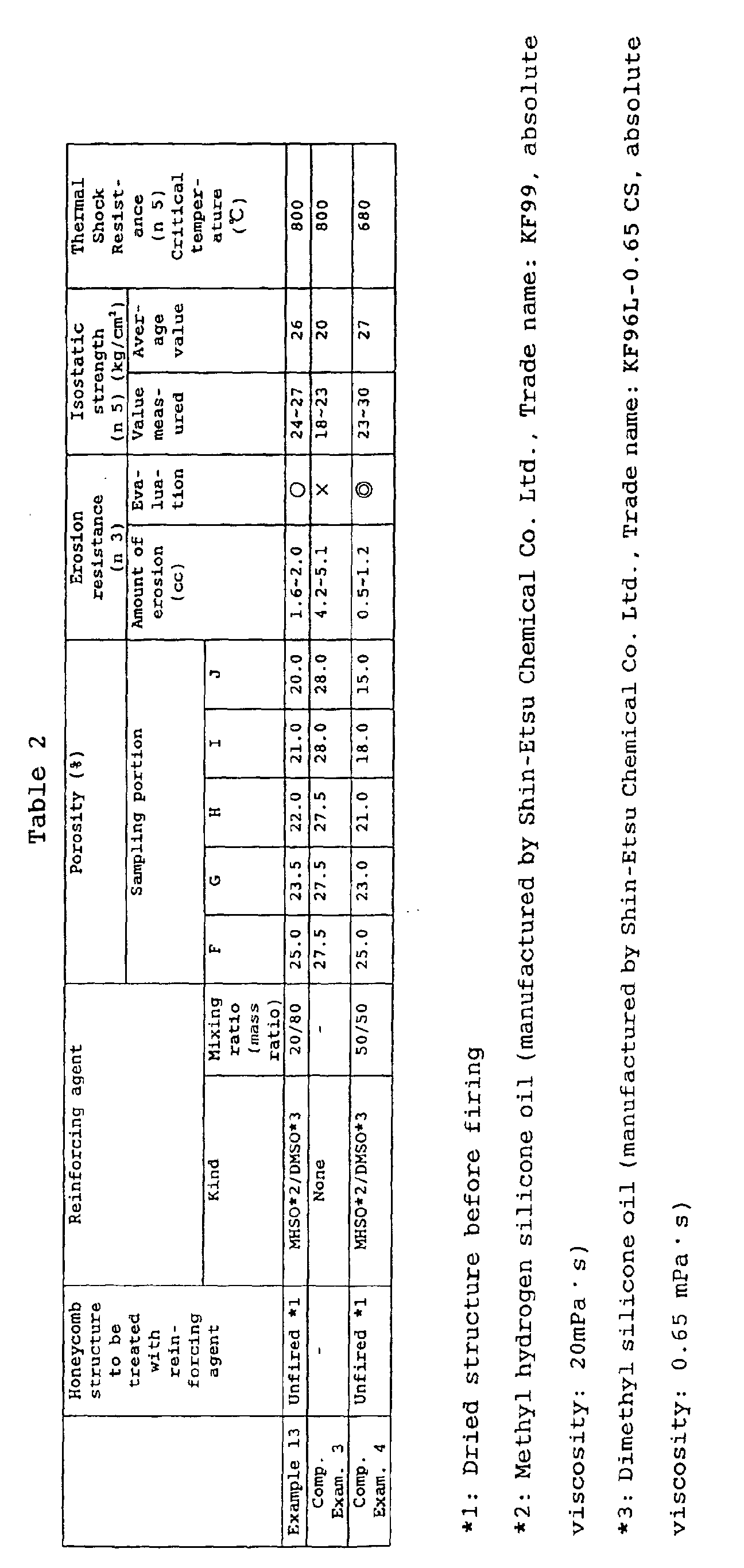
| Porosity (%) | |||||
| Sampling portion (mm) | |||||
| 2.5 | 25 | 50 | 75 | 97.5 | |
| Example 3 | 20 | 21.5 | 23 | 24 | 25 |
| Comparative Example 1 | 27.5 | 28 | 27.5 | 27.5 | 28 |
| Comparative Example 2 | 20 | 27 | 28 | 27.5 | 28 |
As is clear from the results shown in Table 1, the
ceramics honeycomb structures of Examples 1-12 were improved
in erosion resistance and isostatic strength as compared with
the ceramics honeycomb structure of Comparative Example 1, and
were improved in isostatic strength and thermal shock
resistance as compared with the ceramics honeycomb structure
of Comparative Example 2. The reasons for the ceramics
honeycomb structures of Examples 1-12 being superior in erosion
resistance to the ceramics honeycomb structure of Comparative
Example 1 can be considered that the porosity in the inflow end
part (A) was lower than that in the outflow end part (E) , and
the porosity in the inflow end part (A) was 25% or lower in
Examples 1-12 while it was high, namely, 27.5% and low in the
part against which the exhaust gas struck in Comparative
Example 1.
The reasons for the ceramics honeycomb structures of
Examples 1-12 being superior in isostatic strength to the
ceramics honeycomb structures of Comparative Examples 1 and 2
can be considered that the whole of the honeycomb structures
showed a tendency of being lower in porosity although it is
slight, specifically, the average of the porosity of the whole
ceramics honeycomb structures of Examples 1-12 was less than
26% while that of the ceramics honeycomb structures of
Comparative Examples 1 and 2 was 26% or higher and besides the
proportion of the parts having a porosity of 26% or higher was
great. Furthermore, the ceramics honeycomb structures of
Examples 1-12 were superior in thermal shock resistance to the
ceramics honeycomb structures of Comparative Examples 1 and 2.
It is considered that this is because the ceramics honeycomb
structures of Examples 1-12 had no parts where the porosity
greatly changed and thus showed no abrupt change in the
characteristics such as thermal expansion coefficient as is
clear from the facts that, for example, the gradual increasing
rate of the porosity per unit volume (cm3) between the sampling
parts (A)-(B) in the ceramics honeycomb structure of
Comparative Example 2 was 0.28%/mm while the gradual increasing
rate of the porosity per unit volume (cm3) between the sampling
parts (A)-(B) in the ceramics honeycomb structure of Example
11 was 0.08%/mm, which means a gentle change of the porosity.
Moreover, the reason can also be considered that as is clear
from the results shown in Table 3 and Fig. 3, the generated heat
stress and residual stress at the time of production decreased
due to the gentle gradual increase of the porosity from the
inflow end part (A) to the outflow end part (E).
Furthermore, it can be seen from the results shown in
Table 2 that the ceramics honeycomb structure of Example 13 was
improved in erosion resistance and isostatic strength as
compared with the ceramics honeycomb structure of Comparative
Example 3. The reason for the ceramics honeycomb structure
of Example 13 being superior in erosion resistance to the
ceramics honeycomb structure of Comparative Example 3 can be
considered that the ceramics honeycomb structure of Example 13
was lower in porosity of the inflow end part as compared with
the ceramics honeycomb structure of Comparative Example 3 since
the ceramics honeycomb structure of Example 13 was produced by
once wholly dipping in the reinforcing agent like the ceramics
honeycomb structures of Examples 1-12. The reason for the
ceramics honeycomb structure of Example 13 being superior in
isostatic strength to the ceramics honeycomb structure of
Comparative Example 3 can be considered that the porosity of
the outer peripheral part (J) was lower than that of the central
part (F). Moreover, the ceramics honeycomb structure of
Example 13 did not show deterioration of thermal shock
resistance as compared with the ceramics honeycomb structure
of Comparative Example 3. It is considered that this is because
the porosity gently gradually decreases from the central part
(F) to the outer peripheral part (J) and hence the generated
heat stress and the residual stress at the time of production
did not increase.
Moreover, when Comparative Example 4 is compared with
Example 13, Comparative Example 4 gave erosion resistance and
isostatic strength equal to or higher than that of Example 13,
but the thermal shock resistance of Comparative Example 3 was
extremely inferior. It is considered that this is because the
gradual decreasing rate of the porosity per unit volume (cm3)
from the central part (F) to the outer peripheral part (J) was
greater as compared with Example 13.
As explained above, the ceramics honeycomb structure of
the present invention has a structure in which a porosity per
unit volume (cm3) gradually increases from the inflow end part
side to the outflow end part side at a rate lower than a given
rate, and hence it has an excellent erosion resistance,
isostatic strength and thermal shock resistance.
Furthermore, there is provided a method for producing the
ceramics honeycomb structure according to which a substrate (a
dried substrate before firing) or a fired substrate having a
honeycomb structure obtained using a given clay is coated and
impregnated with a given reinforcing agent and then fired (or
refired) and this method hardly causes defects such as
distortion of partition walls and hardly gives variation in
physical properties between the products.
Claims (20)
- A ceramics honeycomb structure formed of a plurality of cells forming a fluid flow passage partitioned by porous partition walls, and comprising an inflow end part allowing fluid to flow therein, an outflow end part allowing fluid to flow therefrom, and an outer peripheral part including an outer peripheral surface, characterized by having a structure where a porosity per unit volume (cm3) gradually increases from the inflow end part side to the outflow end part side at a rate of 0.2%/mm or less.
- A ceramics honeycomb structure according to claim 1 which has a structure where the porosity per unit volume (cm3) gradually increases from the inflow end part side to the outflow end part side at a rate of 0.1%/mm or less.
- A ceramics honeycomb structure formed of a plurality of cells forming a fluid flow passage partitioned by porous partition walls, and comprising an inflow end part allowing fluid to flow therein, an outflow end part allowing fluid to flow therefrom and an outer peripheral part including an outer peripheral surface, characterized by having a structure where a porosity per unit volume (cm3) gradually decreases from the central part of a section perpendicular to the flow passage direction of the cells to the outer peripheral part at a rate of 0.2%/mm or less.
- A ceramics honeycomb structure according to claim 3 which has a structure where the porosity per unit volume (cm3) gradually decreases from the central part of a section perpendicular to the flow passage of the cells to the outer peripheral part at a rate of 0.1%/mm or less.
- A ceramics honeycomb structure according to any one of claims 1-4, wherein a porosity per unit volume (cm3) in the area of up to 150 mm from the flow passage end face of the inflow end part side in the inward direction of the flow passage is 10-50%.
- A ceramics honeycomb structure according to any one of claims 1-5, wherein the minimum thickness of the partition walls is 0.030-0.076 mm.
- A ceramics honeycomb structure according to any one of claims 1-6 which comprises at least one ceramics selected from the group consisting of cordierite, alumina, mullite, silicon nitride, aluminum titanate, zirconia and silicon carbide.
- A ceramics honeycomb structure according to any one of claims 1-7, wherein the section perpendicular to the flow passage has a shape of circle, ellipse, oval, trapezoid, triangle, tetragon, hexagon or left and right asymmetric irregular shape.
- A ceramics honeycomb structure according to any one of claims 1-8, wherein the section of the cells perpendicular to the flow passage has a shape of triangle, tetragon or hexagon.
- A ceramics honeycomb structure according to any one of claims 1-9 which is used as automobile exhaust gas purification catalyst carriers.
- A ceramics honeycomb structure according to any one of claims 1-10 which has a catalyst component supported on the partition walls and is incorporated into a catalyst converter by being held at the outer peripheral surface of the outer wall.
- A method for producing a ceramics honeycomb structure, characterized in that a dried substrate having a honeycomb structure is obtained using a clay mainly composed of a ceramics material, the resulting substrate is coated and impregnated with a reinforcing agent mainly composed of a compound having in its structure at least one element selected from the group consisting of Si, Ti, Mg and A1, and thereafter the substrate is fired.
- A method for producing a ceramics honeycomb structure, characterized in that a dried substrate having a honeycomb structure is obtained using a clay mainly composed of a ceramics material, the substrate is fired to obtain a fired substrate, the resulting fired substrate is coated with and impregnated with a reinforcing agent mainly composed of a compound having in its structure at least one element selected from the group consisting of Si, Ti, Mg and A1, and thereafter the substrate is fired again.
- A method for producing a ceramics honeycomb structure according to claim 12 or 13, wherein said compound is one which produces an inorganic oxide when it burns.
- A method for producing a ceramics honeycomb structure according to any one of claims 12-14, wherein said compound has a siloxane bond.
- A method for producing a ceramics honeycomb structure according to any one of claims 12-15, wherein said compound is a silicone oil, a silicone varnish, an alkoxy oligomer or a mixture thereof.
- A method for producing a ceramics honeycomb structure according to any one of claims 12-16, wherein the reinforcing agent has an absolute viscosity of 1-10000 mPa · s.
- A method for producing a ceramics honeycomb structure according to any one of claims 12-17, wherein the ceramics material is a raw material convertible into cordierite.
- A method for producing a ceramics honeycomb structure according to any one of claims 12-18, wherein the clay contains a water-soluble organic binder.
- A method for producing a ceramics honeycomb structure according to claim 19, wherein the water-soluble organic binder comprises at least one water-soluble compound selected from the group consisting of hydroxypropylmethyl cellulose, methyl cellulose, hydroxyethyl cellulose, carboxymethyl cellulose, polyvinyl alcohol and polyvinyl acetal.
Applications Claiming Priority (5)
| Application Number | Priority Date | Filing Date | Title |
|---|---|---|---|
| JP2002123463 | 2002-04-25 | ||
| JP2002123463 | 2002-04-25 | ||
| JP2003056524 | 2003-03-04 | ||
| JP2003056524A JP4545383B2 (en) | 2002-04-25 | 2003-03-04 | Ceramic honeycomb structure and manufacturing method thereof |
| PCT/JP2003/004622 WO2003090929A1 (en) | 2002-04-25 | 2003-04-11 | Ceramics honeycomb structural body and method of manufacturing the structural body |
Publications (2)
| Publication Number | Publication Date |
|---|---|
| EP1498179A1 true EP1498179A1 (en) | 2005-01-19 |
| EP1498179A4 EP1498179A4 (en) | 2007-08-29 |
Family
ID=29272344
Family Applications (1)
| Application Number | Title | Priority Date | Filing Date |
|---|---|---|---|
| EP03717565A Withdrawn EP1498179A4 (en) | 2002-04-25 | 2003-04-11 | CORE STRUCTURAL BODY OF BEES AND METHOD FOR PRODUCING THE STRUCTURAL BODY |
Country Status (5)
| Country | Link |
|---|---|
| US (1) | US7344770B2 (en) |
| EP (1) | EP1498179A4 (en) |
| JP (1) | JP4545383B2 (en) |
| AU (1) | AU2003227488A1 (en) |
| WO (1) | WO2003090929A1 (en) |
Cited By (4)
| Publication number | Priority date | Publication date | Assignee | Title |
|---|---|---|---|---|
| EP1547743A4 (en) * | 2002-08-21 | 2006-05-17 | Ngk Insulators Ltd | METHOD FOR MANUFACTURING A HONEYCOMB STRUCTURE |
| US7553349B2 (en) | 2005-08-26 | 2009-06-30 | Corning Incorporated | Composite coatings for thin-walled ceramic honeycomb structures |
| EP2127725A1 (en) * | 2008-05-20 | 2009-12-02 | Ibiden Co., Ltd. | Honeycomb structure and exhaust gas conversion apparatus |
| EP2133132A4 (en) * | 2007-03-30 | 2013-12-18 | Ngk Insulators Ltd | HONEYCOMB SEGMENT AND HONEYCOMB STRUCTURE |
Families Citing this family (16)
| Publication number | Priority date | Publication date | Assignee | Title |
|---|---|---|---|---|
| JP4874123B2 (en) * | 2003-12-31 | 2012-02-15 | コーニング インコーポレイテッド | Ceramic structure with hydrophobic coating |
| US8609581B2 (en) * | 2005-08-31 | 2013-12-17 | Ngk Insulators, Ltd. | Honeycomb structure and honeycomb catalytic body |
| JP5037809B2 (en) * | 2005-10-25 | 2012-10-03 | 日本碍子株式会社 | Honeycomb structure |
| JP5073303B2 (en) * | 2006-03-24 | 2012-11-14 | 日本碍子株式会社 | Catalytic converter and manufacturing method of catalytic converter |
| JP5090673B2 (en) | 2006-06-13 | 2012-12-05 | トヨタ自動車株式会社 | Honeycomb carrier for catalyst and exhaust gas purification catalyst using the same |
| JP4963380B2 (en) * | 2006-07-26 | 2012-06-27 | トヨタ自動車株式会社 | Exhaust gas purification catalyst and method for producing the same |
| JP5647051B2 (en) * | 2011-03-25 | 2014-12-24 | 日本碍子株式会社 | Ceramic dry body, ceramic structure, and method for manufacturing ceramic structure |
| JP5658067B2 (en) * | 2011-03-25 | 2015-01-21 | 日本碍子株式会社 | Ceramic molded body, ceramic structure, and method for manufacturing ceramic structure |
| US9011583B2 (en) | 2011-04-29 | 2015-04-21 | Corning Incorporated | Article for CO2 capture having heat exchange capability |
| US9062586B2 (en) * | 2012-04-05 | 2015-06-23 | Corning Incorporated | Impermeable polymer coating on selected honeycomb channel surfaces |
| JP6396240B2 (en) * | 2015-03-17 | 2018-09-26 | 日本碍子株式会社 | Erosion evaluation method for honeycomb structure |
| JP6881337B2 (en) * | 2018-01-30 | 2021-06-02 | 株式会社デンソー | Honeycomb structure and mold |
| JP7062493B2 (en) * | 2018-03-30 | 2022-05-06 | 日本碍子株式会社 | Honeycomb structure for supporting catalyst and its manufacturing method |
| CN110477456B (en) * | 2019-08-02 | 2024-07-16 | 深圳麦克韦尔科技有限公司 | Porous structure assembly and electronic cigarette |
| JP7594471B2 (en) * | 2021-03-16 | 2024-12-04 | 日本碍子株式会社 | Honeycomb structure and electrically heated carrier |
| CN120115013B (en) * | 2025-05-13 | 2025-07-22 | 蓝星(杭州)膜工业有限公司 | Organic solvent resistant composite nanofiltration membrane and its preparation method and application |
Family Cites Families (7)
| Publication number | Priority date | Publication date | Assignee | Title |
|---|---|---|---|---|
| US4255316A (en) | 1979-04-26 | 1981-03-10 | Dow Corning Corporation | Ceramifiable silicone adhesives |
| JPH0657624B2 (en) | 1987-11-30 | 1994-08-03 | イビデン株式会社 | Silicon carbide honeycomb structure and method for manufacturing the same |
| JPH0657623B2 (en) | 1987-11-30 | 1994-08-03 | イビデン株式会社 | Silicon carbide honeycomb structure and method for manufacturing the same |
| JP3394505B2 (en) * | 1998-03-31 | 2003-04-07 | 日本碍子株式会社 | High strength thin-walled honeycomb structure |
| JP3867439B2 (en) * | 1998-06-03 | 2007-01-10 | 株式会社デンソー | Honeycomb structure and manufacturing method thereof |
| JP2001226173A (en) | 1999-12-07 | 2001-08-21 | Denso Corp | Method for manufacturing honeycomb structure |
| JP4259703B2 (en) * | 1999-12-07 | 2009-04-30 | 株式会社デンソー | Ceramic honeycomb structure and manufacturing method thereof |
-
2003
- 2003-03-04 JP JP2003056524A patent/JP4545383B2/en not_active Expired - Fee Related
- 2003-04-11 US US10/510,047 patent/US7344770B2/en not_active Expired - Lifetime
- 2003-04-11 WO PCT/JP2003/004622 patent/WO2003090929A1/en not_active Ceased
- 2003-04-11 AU AU2003227488A patent/AU2003227488A1/en not_active Abandoned
- 2003-04-11 EP EP03717565A patent/EP1498179A4/en not_active Withdrawn
Cited By (6)
| Publication number | Priority date | Publication date | Assignee | Title |
|---|---|---|---|---|
| EP1547743A4 (en) * | 2002-08-21 | 2006-05-17 | Ngk Insulators Ltd | METHOD FOR MANUFACTURING A HONEYCOMB STRUCTURE |
| US7501158B2 (en) | 2002-08-21 | 2009-03-10 | Ngk Insulators, Ltd. | Method for manufacturing honeycomb structure |
| US7553349B2 (en) | 2005-08-26 | 2009-06-30 | Corning Incorporated | Composite coatings for thin-walled ceramic honeycomb structures |
| EP2133132A4 (en) * | 2007-03-30 | 2013-12-18 | Ngk Insulators Ltd | HONEYCOMB SEGMENT AND HONEYCOMB STRUCTURE |
| EP2127725A1 (en) * | 2008-05-20 | 2009-12-02 | Ibiden Co., Ltd. | Honeycomb structure and exhaust gas conversion apparatus |
| US8609031B2 (en) | 2008-05-20 | 2013-12-17 | Ibiden Co., Ltd. | Honeycomb structure, exhaust gas conversion apparatus, and manufacturing method of the honeycomb structure |
Also Published As
| Publication number | Publication date |
|---|---|
| WO2003090929A1 (en) | 2003-11-06 |
| JP4545383B2 (en) | 2010-09-15 |
| AU2003227488A1 (en) | 2003-11-10 |
| US20050181172A1 (en) | 2005-08-18 |
| US7344770B2 (en) | 2008-03-18 |
| EP1498179A4 (en) | 2007-08-29 |
| JP2004000907A (en) | 2004-01-08 |
Similar Documents
| Publication | Publication Date | Title |
|---|---|---|
| US7344770B2 (en) | Ceramics honeycomb structural body and method of manufacturing the structural body | |
| JP4294964B2 (en) | Manufacturing method of ceramic honeycomb structure | |
| JP4459476B2 (en) | Porous honeycomb structure and manufacturing method thereof | |
| US7208108B2 (en) | Method for producing porous ceramic article | |
| JP5144075B2 (en) | Honeycomb structure and manufacturing method thereof | |
| CA2396846C (en) | Porous honeycomb filter and method for manufacture thereof | |
| US20030153459A1 (en) | Electron beam apparatus and device manufacturing method using the electron beam apparatus | |
| EP2119487A1 (en) | Honeycomb structure and method for manufacturing the same | |
| EP2236482A2 (en) | Ceramic honeycomb structure | |
| KR20040030633A (en) | Honeycomb structural body, method of manufacturing the structural body, and method of measuring outer peripheral distortion of the structural body | |
| JP2003277162A (en) | Porous honeycomb structure, its use, and method of manufacturing the same | |
| JP2003095768A (en) | Honeycomb structure and manufacturing method thereof | |
| JP2004315346A (en) | Honeycomb structure | |
| JPWO2005094967A1 (en) | Honeycomb structure and manufacturing method thereof | |
| CN108568209B (en) | Honeycomb structure | |
| US7897099B2 (en) | Method for producing honeycomb structure | |
| US20060280905A1 (en) | Honeycomb structure | |
| JP6013243B2 (en) | Honeycomb catalyst body | |
| JPWO2005068396A1 (en) | Honeycomb structure and manufacturing method thereof | |
| US7501158B2 (en) | Method for manufacturing honeycomb structure | |
| ZA200408025B (en) | Ceramics honeycomb structural body and method of manufacturing the structural body. | |
| JP2001205082A (en) | Cordierite ceramic honeycomb structured catalyst support and method for producing the same | |
| ZA200406928B (en) | Ceramic honeycomb structural body and method of manufacturing the structural body | |
| JP2004074593A (en) | Manufacturing method for honeycomb structure | |
| KR20050031065A (en) | Honeycomb structure and process for production thereof |
Legal Events
| Date | Code | Title | Description |
|---|---|---|---|
| PUAI | Public reference made under article 153(3) epc to a published international application that has entered the european phase |
Free format text: ORIGINAL CODE: 0009012 |
|
| 17P | Request for examination filed |
Effective date: 20041015 |
|
| AK | Designated contracting states |
Kind code of ref document: A1 Designated state(s): AT BE BG CH CY CZ DE DK EE ES FI FR GB GR HU IE IT LI LU MC NL PT RO SE SI SK TR |
|
| AX | Request for extension of the european patent |
Extension state: AL LT LV MK |
|
| A4 | Supplementary search report drawn up and despatched |
Effective date: 20070727 |
|
| 17Q | First examination report despatched |
Effective date: 20090626 |
|
| STAA | Information on the status of an ep patent application or granted ep patent |
Free format text: STATUS: THE APPLICATION IS DEEMED TO BE WITHDRAWN |
|
| 18D | Application deemed to be withdrawn |
Effective date: 20091109 |