EP1498151A2 - Catheter urinaire prélubrifié et ensemble d'emballage - Google Patents
Catheter urinaire prélubrifié et ensemble d'emballage Download PDFInfo
- Publication number
- EP1498151A2 EP1498151A2 EP04022127A EP04022127A EP1498151A2 EP 1498151 A2 EP1498151 A2 EP 1498151A2 EP 04022127 A EP04022127 A EP 04022127A EP 04022127 A EP04022127 A EP 04022127A EP 1498151 A2 EP1498151 A2 EP 1498151A2
- Authority
- EP
- European Patent Office
- Prior art keywords
- catheter
- package
- end portion
- receiving chamber
- guide
- Prior art date
- Legal status (The legal status is an assumption and is not a legal conclusion. Google has not performed a legal analysis and makes no representation as to the accuracy of the status listed.)
- Withdrawn
Links
Images


Classifications
-
- A—HUMAN NECESSITIES
- A61—MEDICAL OR VETERINARY SCIENCE; HYGIENE
- A61M—DEVICES FOR INTRODUCING MEDIA INTO, OR ONTO, THE BODY; DEVICES FOR TRANSDUCING BODY MEDIA OR FOR TAKING MEDIA FROM THE BODY; DEVICES FOR PRODUCING OR ENDING SLEEP OR STUPOR
- A61M25/00—Catheters; Hollow probes
- A61M25/01—Introducing, guiding, advancing, emplacing or holding catheters
- A61M25/0105—Steering means as part of the catheter or advancing means; Markers for positioning
- A61M25/0111—Aseptic insertion devices
-
- A—HUMAN NECESSITIES
- A61—MEDICAL OR VETERINARY SCIENCE; HYGIENE
- A61M—DEVICES FOR INTRODUCING MEDIA INTO, OR ONTO, THE BODY; DEVICES FOR TRANSDUCING BODY MEDIA OR FOR TAKING MEDIA FROM THE BODY; DEVICES FOR PRODUCING OR ENDING SLEEP OR STUPOR
- A61M25/00—Catheters; Hollow probes
- A61M25/002—Packages specially adapted therefor ; catheter kit packages
Definitions
- This invention relates generally to urinary catheters and more prelubricated intermittent urinary catheter and package assemblies.
- Another problem associated with the prior art is that it is difficult to insure that the catheter is properly lubricated for insertion. This is because the lubricant is designed to liquify at body temperature and frequently becomes sufficiently liquid during storage to coat the inside of the package carrying the catheter and also the complete catheter. As a result, the prior art has frequently supplied the lubricant in a separate container. With most prior art prelubricated catheters, the catheter is stowed in a curved shape. Sometimes, the catheter retained this curved shape during use thereby making the catheter more difficult and uncomfortable to use.
- a urinary catheter and package assembly which provides a prelubricated catheter in a straight condition for intermittent use. This serves to facilitate the use of the catheter.
- the catheter is used without having to be completely removed from the package to reduce the likelihood of contamination and the package can be used as a drainage extension to further facilitate the use of the catheter.
- Guide means is provided to locate the catheter as it is extended from the package to facilitate gripping the catheter and controlling its position relative to the package.
- Extension control means is provided to help the user manipulate the catheter within the package as it is being extended.
- the extension control means is designed to grip the catheter in such a way that the user does not have to maintain their grip on the catheter as the package is being moved relative to the catheter during manipulation for extension.
- the catheter is inserted using the packaging so that the user never has to touch the catheter itself.
- the packaging is such that the lubricant is applied to the projecting end of the catheter in the package in such a way as to insure that the catheter is adequately lubricated for use.
- Manually operated lubricate applicator means may be provided to insure that lubricant is forced onto the catheter within the package either before or during extension. Because the drainage end of the catheter can be left within one end of the packaging, the rest of packaging can be pulled over the drainage end of the catheter to act as a drainage extension for the catheter since the remaining lubricant within the packaging serves as a sufficient seal between the catheter and the packaging to prevent leakage.
- the apparatus of the invention is directed to a prelubricated urinary catheter and package assembly for use in draining the bladder through the urethra comprising a package with opposed first and second ends and defining a sealed elongate catheter receiving chamber therein extending for a minimum prescribed length along the length of the package; an elongate catheter with opposed projecting and drainage ends and a maximum length less than the minimum prescribed length of the catheter receiving chamber in the package, the catheter being carried in the sealed elongate catheter receiving chamber in a generally straight condition with the projecting end of the catheter located at that end of the catheter receiving chamber with the opening initiating means so that the projecting end of the catheter can pass out of the catheter receiving chamber when a manual opening is formed in the end of the package; and guide means operatively associated with the first end of the package and defining a catheter guide passage oriented generally along the longitudinal axis through the package where the catheter receiving opening communicates with the elongate catheter receiving chamber and is operatively associated with the first opening initiating means so that the catheter receiving opening remains sealed until
- One or both of the ends of the package may include opening initiating means for controlling the manual opening of the catheter chamber at that end associated with the opening initiating means.
- the opening initiating means may include a tear initiating arrangement, a peel apart arrangement, or an axial cut in the end of the package.
- the opening initiating means may be constructed and arranged so as to not expose the catheter to a contaminated surface as it is extended from the package.
- the guide means may comprise a preformed guide member defining the catheter guide passage therethrough held in place within the sealed catheter receiving chamber adjacent the first end of the package.
- the guide member may be flexible or rigid.
- the guide means may alternatively comprise a guide strip bonded to one side of the package at the first end so that the guide strip lies adjacent the sealed catheter receiving chamber in the package before the package is opened and extends across the opening in the first end of the package when the package is opened, where the guide passage is formed by the guide strip defining a guide recess thereacross generally in alignment with the first axis of the package and forming an opening thereinto along the length thereof facing the opposite side of the package and by the opposite of the package extending across the opening into the recess to close same.
- the guide strip may be affixed to the exterior or interior of the side of the package. Where the guide strip is affixed to the exterior of the package, that side of the package immediately adjacent guide strip is affixed to and extends into the guide recess in the guide strip to form a conforming recess therein matching the guide recess in the guide strip so that the catheter receiving opening is defined between the sides of the package.
- Gripping means may be provided for the user to grip the catheter at the guide means so as to longitudinally fix the catheter relative to the guide means.
- the gripping means may be incorporated in the guide means to facilitate manufacture and assembly of the package and catheter assembly.
- the catheter can be gripped by the user pressing that side of the package opposite the guide strip into the recess in the guide strip to frictionally engage the catheter between the guide strip and the opposite side of the package.
- the extension control means may comprise gripping members sized and configured so as to grip the catheter tube of the catheter sufficiently to require a minimum threshold force to move the catheter with respect to the extension control means.
- the minimum threshold force may be selected at a value such that the package can be moved relatively to the catheter when manually released yet the catheter can be gripped through the package to move the catheter through the extension control means.
- the extension control means may also be arranged so as to act as a one-way clutch mechanism to easily permit extension of the catheter from the package but to substantially prevent retraction of the catheter back into the package.
- the extension control means may be incorporated in the guide means as control protrusions or may be a separate control member that cooperates with the guide means to engage the catheter.
- the lubricating means may include a lubricant reservoir formed in the package which carries a prescribed quantity of lubricant for application to the catheter during use.
- the catheter may also be lubricated with additional lubricant in the catheter receiving chamber and the catheter receiving passage of the guide means.
- the lubricating means may be constructed and arranged such that the user can manually press in on the package in the vicinity of the lubricant reservoir to force the lubricant onto the catheter as it passes the lubricant reservoir during extension of the catheter from the package.
- the guide means may also be constructed and arranged to permit the lubricant to be injected into the guide passage around the catheter from the lubricant reservoir.
- the package may be comprised of a base sheet of material in which a catheter receiving recess is formed with the recess opening onto one side of the sheet to form a loading opening extending along the length of the recess and with the catheter receiving recess having a length and cross-sectional size and shape corresponding to that of the catheter receiving chamber; and, a cover sheet of material covering the loading opening with the base sheet and the cover sheet sealed to each other around the loading opening to form the sealed catheter receiving chamber between the base sheet and the cover sheet.
- the seal between the base sheet and the cover sheet may be an adhesive or a heat weld formed with the material of the base sheet and cover sheet.
- the base sheet of material and the cover sheet of material may each define a projecting end section thereon located outboard of the seal with respect to the catheter receiving chamber, with the projecting end sections not connected to each other and with the opening initiating means located in the projecting end sections of the base and cover sheets outboard of the seal.
- the lubricant may extend from that end of the catheter chamber at the projecting end of the catheter for about 1/4-1/2 the length of the chamber and the viscosity range of the lubricant may be selected so that the lubricant does not significantly flow along the length of the catheter at normal storage temperature but readily flows at normal body temperature.
- the guide means may be located within the package so that the projecting end of the catheter is located within the catheter receiving opening defined by the guide means when the catheter receiving chamber is sealed and the guide means may be constructed and arranged so that the catheter can be gripped through the package at the guide means by manually pressing opposite sides of the package together at the guide means with guide means constructed and arranged to normally maintain the catheter receiving opening at a cross-sectional size and shape larger than the cross-sectional diameter of the projecting end of the catheter when the package is manually released.
- the guide means may be affixed to the package so that the guide means is axially fixed relative to the package.
- the guide means may comprise a resilient tubular guide member having opposed ends thereon bonded to the package at said first end so that the tubular guide member lies within the sealed catheter receiving chamber in the package before the package is opened and projects out of the opening in the first end of the package when the package is opened, where the guide member defines the catheter receiving opening therethrough opening onto the opposed ends of the guide member so that the guide member will slidably pass therethrough, and where the guide member normally has a generally circular configuration in its relaxed condition so that the guide member can be manually pressed together to cause the guide member to grip the catheter and the guide member will return toward its normally relaxed condition when released to permit the catheter to pass therethrough.
- the guide means may comprise a preformed guide strip bonded to one side of the package at the first end so that the guide member lies adjacent the sealed catheter receiving chamber in the package before the package is opened and extends along one side of the opening in the first end of the package when the package is opened with the guide member defining a recess thereacross generally in alignment with the first axis through the package and with that side of the package immediately adjacent the guide member affixed to and extending into the recess to form a conforming recess to the recess in the guide member so that the conforming recess formed in the side of the package has a cross-sectional size and shape to slidably receive the catheter therethrough to define the catheter receiving opening between the sides of the package whereby the guide member and that side of the package opposite the guide member can be manually pressed together to cause the catheter to be gripped through the sides of the package yet the catheter will be released to freely slide through the catheter receiving opening when the guide strip and the opposite side of the package are released to permit the catheter to pass therethrough.
- the method of packaging of the invention is directed to a method of packaging urinary catheters of a prescribed length and with a projecting end for use in catheterizing patients comprising the steps of: a) forming a primary recess in a base sheet of material sized to receive the catheter therein where the recess has a first end along with a secondary guide recess adjacent the first end to slidably guide the catheter; and, b) depositing a lubricant in the recess so that the lubricant extends from the first end of the recess a prescribed distance toward the opposite end of the recess and so that the lubricant does not overfill the recess when the catheter is also located in the recess.
- the method of packaging may also include the step of placing one of the catheters in the recess so that the projecting end of the catheter is located at the first end of the recess prior to step b).
- the method of packaging may also comprise the steps of placing a cover sheet of material over the base sheet of material so that the cover sheet covers the recess; and, sealing the cover sheet to the base sheet around the recess so as to seal the recess with the catheter and lubricant therein.
- the method of packaging may also comprise the step of forming a weakened section in the base and cover sheets in the vicinity of the first end so that the first end of the package can be manually opened at the weakened section.
- the method of using the catheter and package assembly is directed to a method of using a urinary catheter carried within an elongate sealed package where the catheter has a projecting end located at a first end of the sealed package and a discharge end opposite the projecting end, and where guide means is provided within the sealed chamber at the first to guide the catheter out of the chamber, and lubricant is provided within the package about the projecting end of the catheter comprising the steps of a) making a first opening through the first end of the package of a sufficient size for the projecting end of the catheter to pass therethrough; b) making a second opening through the package in the vicinity of the discharge end of the catheter; and, c) after the first and second openings are made, manually extending the projecting end of the catheter out of the package by manually gripping and releasing the catheter within the chamber through the guide means while manipulating the catheter through the package.
- a first embodiment 10 of the catheter and package assembly is illustrated in Figs. 1-8, a second embodiment is illustrated in Figs. 9-10, a third embodiment 210 is illustrated in Figs. 11-16, a fourth embodiment is illustrated in Figs. 17-20, a fifth embodiment 410 is illustrated in Figs. 22-26, and a sixth embodiment 510 is illustrated in Figs. 27 and 28.
- a first embodiment 11 of the package is illustrated in Figs. 1-10 and 20, a second embodiment 111 of the package is illustrated in Figs.
- a third embodiment 211 is illustrated in Figs. 22-26
- a fourth embodiment 311 is illustrated in Figs. 27 and 28.
- a first embodiment 14 of the guide means is illustrated in Figs. 1-3A and 4-10
- a second embodiment 114 of the guide means is illustrated in Figs. 11-18
- a third embodiment 214 of the guide means is illustrated in Figs. 22-26
- a fourth embodiment 314 of the guide means is illustrated in Figs. 27 and 28.
- a first embodiment 15 of the gripping means is illustrated in Figs. 1-10
- a second embodiment 115 is illustrated in Figs. 22-26
- a third embodiment 215 is illustrated in Figs. 27-28.
- a first embodiment 16 of the extension control means is illustrated in Figs. 1-8, a second embodiment 116 is illustrated in Figs. 9 and 10, a third embodiment 216 is illustrated in Figs. 11-16, and a fourth embodiment 316 is illustrated in Figs. 17-20.
- a first embodiment 18 of the lubricating means is illustrated in Figs. 1-8, a second embodiment 118 is illustrated in Figs. 11-13, and a third embodiment 218 is illustrated in Figs. 22-31.
- the catheter and package assembly 10 includes package 11, a catheter 12 carried in the package 11, guide means 14 adjacent one end of the package 11, gripping means 15 on the guide means 14, extension control means 16 also on the guide means 14, and lubricating means 18 around a portion of the catheter 12 in the package 11.
- the guide means 14 helps the user guide the catheter 12 as it is extended from the package 11 while the gripping means 15 facilitates the user gripping the catheter 12 through the package for manipulating the catheter within the package.
- the extension control means 16 serves to prevent the catheter 12 from being inadvertently retracted back into the package 11 when the package is moved relative to the catheter for extension from the package.
- the lubricating means 18 serves to prelubricate the catheter 12 so that the catheter 12 is ready to use as it is extended from the package 11.
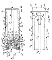
- the package 11 has an elongate rectilinear shape with opposed first and second end portions 21 and 22 respectively and opposed side portions 24.
- the package 11 has an overall length L 1 and an overall width W 1 as best seen in Fig. 1.
- the package 11 defines a sealed elongate catheter receiving chamber 25 therein about the longitudinally extending first axis A 1 through the package.
- the sealed elongate catheter receiving chamber 25 extends along the first axis A 1 from the first end portion 21 to the second end portion 22 so that the chamber 25 has a minimum prescribed length L 2 as will become more apparent.
- the package 11 projects beyond the chamber 25 on both ends for a projection distance D 1 also seen in Fig.1.
- the package 11 is formed with a base sheet 30 and a cover sheet 31 of material which is at least semiflexible and which does not allow contaminates to pass therethrough to maintain the catheter 12 in a sterile condition until ready for use.
- a base sheet 30 and a cover sheet 31 of material which is at least semiflexible and which does not allow contaminates to pass therethrough to maintain the catheter 12 in a sterile condition until ready for use.
- the sheets 30 and 31 is made of flexible transparent or translucent plastic of the type commonly used in the medical products industry to maintain medical products sterile.
- a number of different materials may be used for one or both sheets 30 and 31 without departing from the scope of the invention. The kind of materials will also depend on the method by which the package 11 is to be opened as will become more apparent.
- the sheets 30 and 31 are illustrated with common lengths L 1 and common widths W 1 .
- the catheter receiving chamber 25 is formed between the sheets 30 and 31 with the sheets 30 and 31 sealed together around the chamber 25 with a composite seal indicated generally at 32.
- the seal can be formed by any convenient means such as with a heat activated adhesive for the seal 32 or by heat sealing the sheets directly to each other as illustrated in Fig. 11 for the seal 132.
- a heat activated strippable adhesive is used to form the seal 32 with the material commonly used for the sheets 30 and 31 being a coextrusion of polyvinylchloride (PVC) and polyethylene.
- PVC polyvinylchloride
- a polyethylene is typically used with an oriented grain for the sheets 130 and 131.
- the sheets 130 and 131 are heat sealed directly to each other.
- the polyethylene material is such that, once a tear is started, the sheets will tear straight across the package to form a straight edge at the tear. It will be appreciated that the seals 32 or 132 can be interchanged with each other without departing from the scope of the invention.
- the composite seal 32 comprises a primary package forming seal 34 and a closing seal 35.
- the primary package forming seal 34 is used to form the basic package 11 but leaves the catheter receiving chamber open at the first end portion 21 of the package so that the catheter 12 and guide means 14 can be loaded into the package.
- the closing seal 35 serves to seal the catheter receiving chamber 25 after the catheter and guide are loaded.
- the package forming seal 34 has opposed side sections 36 that extend along opposite sides of the package 11 and an end section 38 at the second end portion 22 of the package 11 joining the side sections 36 to close the catheter receiving chamber 25 at the second end portion of the package.
- the closing seal 35 joins the side sections 36 at the first end portion 21 of the package 11 to close the catheter receiving chamber.
- the catheter receiving chamber 25 has different coaxially arranged subchambers to maintain the catheter 12 and guide means 14 in place within the package 11.
- a lubricant subchamber 40 of chamber 25 is formed in the package 11 at the first end portion 21 and forms part of the lubricating means 18.
- a guide retaining subchamber 41 of chamber 25 is formed in the package adjacent the lubricant subchamber 40 and communicates with the subchamber 40 through a smaller central opening 42 formed by first separation projections 44 in the side sections 36 of seal 34.
- a catheter subchamber 45 of chamber 25 is formed in the package 11 adjacent that side of the guide retaining subchamber 41 opposite the lubricant subchamber 40 and communicates with the subchamber 41 through a smaller central opening 46 formed by second separation projections 48.
- the end section 38 of the primary seal 34 forms a discharge subchamber 49 of chamber 25 in the package 11 at that end of the catheter subchamber 45 opposite the guide retaining subchamber 41.
- the discharge subchamber 49 forms an extension of the catheter subchamber 45 and projects into the second end portion 22 of the package 11.
- Each side section 36 of the primary seal 34 has a side portion 50 which extends along the length of the chamber 25 with the first and second separator projections 44 and 46 projecting inwardly therefrom.
- Third separator projections 51 form a portion of the lubricant subchamber 40 on that side of the subchamber 40 opposite the guide retaining subchamber 41.
- the projections 51 define a loading opening 52 therebetween through which the catheter 12 and guide means 14 are loaded into the package 11 as will become more apparent.
- the size of the lubricant subchamber 40 is determined by the amount of lubricant needed for application to the catheter 12 as will become apparent.
- the guide retaining subchamber 41 is sized so that the guide means 14 will be captivated therein as will become more apparent.
- the catheter subchamber 45 is sized to locate the catheter 12 within the guide means 14 as will become more apparent.
- the discharge subchamber 49 is sized and configured to direct urine out of the chamber 25 when the package 11 is used as an extension to the catheter 12 and to prevent the catheter 12 from inadvertently dropping out of the package 11 when the end portion 22 is opened as will become more apparent.
- the loading opening 52 as well as the central openings 42 and 46 are sized so that the guide means 14 in a collapsed condition can pass therethrough for loading as will become more apparent.
- the end section 38 joins the side portions 50 of the side sections 36 at the second end portion 22 of the package 11 and extends out from the end of the chamber 25 a distance less than the projection distance D 1 so that the sheets 30 and 31 project beyond the ends of the chamber 25 to form nonattached projecting end portions 60 and 61 in the sheets 30 and 31 respectively outboard of the end section 38 of the seal 34.
- the end portions 60 and 61 form part of the second opening initiating means 62 and are adapted to be manually gripped to facilitate the opening of the discharge end of the package 11 as will become apparent.
- the closing seal 35 serves to close the loading opening 52 between the separator projections 51 to seal the catheter receiving chamber 25.
- the closing seal 35 extends across the full width of the package 11 and is provided with a confining projection 65 that extends from the base band 66 of the seal 35 toward the lubricant subchamber 40.
- the projection 65 defines a recess therein forming a reduced diameter passage 68 centered on axis A 1 and opening into the lubricant subchamber 40.
- the opposite end of the passage 68 is initially closed by the base band 66 to maintain the catheter receiving chamber 25 sealed.
- the closed end of the passage 68 is opened when the user opens the package 11 to allow the catheter 12 to move out through the passage 68.
- the closing seal 35 extends out from the end of the chamber 25 a distance less than the projection distance D 1 so that the sheets 30 and 31 project beyond the ends of the chamber 25 at the first end portion 21 to form nonattached projecting end portions 70 and 71 in the sheets 30 and 31 respectively outboard of the closing seal 35.
- the end portions 70 and 71 form part of the first opening initiating means 72 and are adapted to be manually gripped to facilitate the opening of the first end portion 21 of the package 11 as will become apparent.
- the opening initiating means 62 and 72 are designed to facilitate the manual opening of the ends of the catheter receiving chamber 25 as seen in Figs. 1-3.
- the opening initiating means 62 and 72 are designed to make the package 11 easy to open manually for persons who may have limited manual dexterity and to confine the opening to the ends of the package 11.
- the user grasps the unattached end portions 60 and 61 or 70 and 71 and pulls the sheets 30 and 31 apart until the seal 32 has been peeled back far enough to open the end of the chamber 25 as will become more apparent.
- the catheter 12 corresponds to those catheters currently in use for intermittent catheterization.
- Catheter 12 has a projecting end 54 and an opposed drainage end 55, and includes an elongate catheter tube 56 typically equipped with an enlarged funnel 58 at the drainage end 55.
- the tip of the catheter tube 56 at the projecting end 54 is closed and equipped with an inlet opening adjacent the tip to the drain passage that extends from the inlet opening along the length of the catheter tube 56 and out of the end of the funnel 58.
- the length L 3 of the catheter 12 is determined by the physical size of the patient with which the catheter is to be used. A typical length for catheters 12 designed for use with both men and women is about 17-18 inches.
- the length L 3 thus determines the length L 2 of the catheter receiving chamber 25 which must be longer than the length of the catheter 12 so that the catheter 12 will be stowed in the package 11 in a straight condition.
- the catheter tube 56 is round and the funnel 58 is also typically round.
- the funnel 58 has the largest cross-sectional dimension D 3 while the catheter tube 56 has a smaller diameter D 4 .
- the cross-sectional diameter D 4 varies depending on the size of the catheter and typically ranges from 6-22 French.
- the discharge subchamber 49 formed in the chamber 25 has a conical portion 59 therein at the end of the catheter subchamber 45 that tapers down to a discharge passage 64 coaxially aligned with the axis A 1 .
- the discharge passage 64 has a diameter less than the funnel diameter D 3 so that the funnel 58 will not pass out of the discharge passage. Initially, the outer end of the discharge passage 64 is closed by the end section 38 of the seal 34 but is opened when the second end portion 22 of the package 11 is opened as will become more apparent.
- the passage 64 allows the urine to drain out of the package 11 when it is used as a drainage extension as will become more apparent.
- the user grasps the unattached end portions 60 and 61 and pulls the sheets 30 and 31 apart until the end section 38 of the primary seal 34 has been peeled back only far enough to open the end of the passage 64. If, on the other hand, the user wants to slide the package 11 up over the funnel 58 to allow the urine to drain directly out of the discharge end 55 of the catheter, the user continues to pull the sheets 30 and 31 apart to peel back the end section 38 of the primary seal 34 until the conical portion 59 has been opened sufficiently for the end portion 22 of the package 11 to pass over the funnel 58.
- the guide means 14 best seen in Figs. 1-8 assists the user in being able to control the position of the catheter tube 56 as it is extended out of the package 11. Because the cross-sectional size of the recess catheter receiving chamber 25 is considerably larger than that of the catheter tube 56, the catheter tube 56 tends to slip around within the chamber 25 as it is being extended from the package.
- the guide means 14 is located at that end of the package 11 at which the projecting end 54 on catheter 12 is located and serves to guide the catheter tube 56 as it is being extended to facilitate the user controlling the catheter tube. As best seen in Fig.
- the guide means 14 includes a cylindrical tubular guide member 75 having a central axis A 2 and defining a guide passage 76 therethrough concentrically about axis A 2 with a diameter large enough for the catheter tube 56 to freely pass therethrough but smaller than the diameter of the funnel 58 to prevent its passage therethrough.
- the material for the guide member 75 is selected so that the guide member is substantially rigid.
- a guide holding arrangement 78 is provided on the member 75 for use in interconnecting the guide means 14 to the package 11 to keep the guide means 14 fixed relative to a portion of the package.
- the arrangement 78 includes a pair of diametrically outwardly projecting flanges 79 joined to the guide member 75 through a bendable joint 80 so that the flanges 79 can be moved between an erected position in which the flanges 79 are oriented normal to the axis A 2 as seen in Figs. 1 and 2 and a stowed position in which the flanges 79 are bent over to a position generally parallel to the axis A 2 as seen in Fig. 21.
- the gripping means 15 best seen in Fig. 5 is mounted on the guide means 14 and projects outwardly therefrom along the guide axis A 2 .
- the gripping means 14 includes a pair of opposed, spaced apart gripping flanges 81 flexibly connected to that end of the guide member 75 facing the catheter subchamber 45.
- the flanges 81 have a convenient length to permit the user to press inwardly on the flanges through the package 11 to grip the catheter 12 between the flanges 81 to positively lock the catheter 12 to the gripping means 15.
- the flanges 81 When the flanges 81 are released, the natural resiliency of the material from which the flanges 81 are formed moves them back apart to release the catheter tube 56.
- the extension control means 16 best seen in Figs. 5-8 is also mounted on the guide means 14.
- the extension control means 16 is a one-way clutch which permits the catheter 12 to be extended from the package 11 but substantially prevents the catheter 12 from being retracted back into the package 11 once extended.
- the extension control means 16 comprises a plurality of check members 82 on the inside of the guide member 75 and projecting into the guide passage 76. While different numbers of check members 82 may be used without departing from the scope of the invention, three are illustrated for extension control means 16.
- the check members 82 are equally spaced around the inside of the guide member 75 and are arranged in a common plane normal to the guide member axis A 2 .
- Each of the check members 82 includes a sloped surface 84 that faces the catheter subchamber 45 when the guide means is installed in the package 11 and a normal surface 85 that faces in the opposite direction to the sloped surface 84.
- the surfaces 84 and 85 intersect to form a check edge 86 projecting into the guide passage 76.
- the height H 1 of each of the check members 82 is selected so that the check edges 86 subtend a circle inside the guide passage 76 of diameter D 5 as best seen in Fig. 7.
- the diameter D 5 is selected so that it is smaller than the smallest catheter tube diameter D 4 with which the extension control means is to be used.
- the check members 82 are illustrated as substantially rigid so that the check edges 86 are tightly forced against the surface of the catheter tube 56 due to the natural resiliency of the catheter tube maintaining the tube forced against the edges 86.
- the sloped surfaces 84 allow the catheter tube 54 to slide past the check members 82, however, the normal surface 85 serves to cause the check edges 86 to bite into the catheter tube and prevent it from being retracted back into the package 11. This facilitates the use of the catheter 12 because the user does not have to worry about the catheter being withdrawn as that portion of the package 11 spaced from the guide means 14 is shifted relative to the catheter 12 so that the catheter can be inserted further by again grasping the catheter through the package and advance the catheter relative to the guide means 16.
- check members 82 may be necessary to accommodate the different size ranges of catheter tubes 56 although one size of check members 82 may accommodate more than one size of catheter tube depending on the resiliency of the catheter tube itself. Moreover, it will be appreciated that the check members 82 may be fabricated so that they are sufficiently resilient to accommodate a broader range of sizes for the catheter tubes 56 without departing from the scope of the invention.
- extension control means 16 should remove the minimum amount of lubricant from the surface of the catheter tube 56.
- the check members 82 accomplish this by having narrow rounded check edges 86 as best seen in Fig. 6 so that the contact between the check members 82 and the catheter tube 56 is minimized.
- the lubricating means 18 best seen in Figs. 1-3A comprises the lubrication subchamber 40 and a lubricant 28 in the subchamber 40.
- the closing seal 35 closes the subchamber 40 leaving the passage 68 when the first end of the package 11 is opened. Because the sheets 30 and 31 are flexible, the user can either deliberately squeeze the package 11 at the subchamber 40 or inherently squeeze the package 11 in the vicinity of the subchamber 40 as the catheter 12 is being extended. This forces the lubricant 28 around the catheter tube 56 as it passes through the subchamber 40 to insure that the lubricant coats the catheter tube 56. Because each portion of the catheter must pass through the lubrication subchamber 40 after it passes the extension control means 16, any lubricant 28 removed from the tube 56 is replenished before the catheter tube 56 passes out of the package 11 during use.
- the second embodiment of the catheter and package assembly utilizes those components of the first embodiment except a second embodiment of the extension control means is utilized.
- Figs. 9 and 10 illustrate the second embodiment 116 of the extension control means.
- the extension control means 116 is also mounted on the guide means 14. The extension control means 116 will allow movement of the catheter 12 in either direction through the guide means 14 but serves to prevent movement of the catheter 12 relative to the guide means 14 until a minimum axial force is applied to the catheter tube 56.
- the threshold value of the force required move the catheter tube 56 relative to the guide means 14 is selected sufficiently high so that the package can be moved relative the catheter tube without moving the catheter tube 56 with respect to the guide means 14 yet sufficiently low so that the catheter tube 56 can be moved relative to the guide means 16 when the catheter tube 56 is grasped through the package 11 to advance or retract the catheter tube.
- the extension control means 116 comprises a plurality of limit members 182 on the inside of the guide member 75 and projecting into the guide passage 76. While different numbers of limit members 182 may be used without departing from the scope of the invention, three are also illustrated for extension control means 116.
- the limit members 182 are also equally spaced around the inside of the guide member 75 and are arranged in a common plane normal to the guide member axis A 2 .
- Each of the limit members 182 includes a first sloped surface 184 that faces the catheter subchamber 45 when the guide means is installed in the package 11 and a second sloped surface 185 that faces in the opposite direction to the sloped surface 184.
- the surfaces 184 and 185 intersect to form a rounded retention edge 186 projecting into the guide passage 76.
- the height H 1 of each of the limit members 82 is likewise selected so that the retention edges 186 subtend a circle inside the guide passage 76 of diameter D 5 .
- the diameter D 5 is selected so that it is smaller than the smallest catheter tube diameter D 4 with which the extension control means is to be used.
- the limit members 182 are also illustrated as substantially rigid so that the retention edges 186 are tightly forced against the surface of the catheter tube 56 due to the natural resiliency of the catheter tube maintaining the tube forced against the edges 186.
- the sloped surfaces 184 and 185 allow the catheter tube 54 to slide in either direction past the limit members 182 when the threshold value is exceeded in the pushing force on the catheter tube 56.
- catheter tube 56 can be extended or retracted by grasping the catheter through the package and pushing on the catheter tube with a force exceeding the threshold value.
- limit members 182 may be necessary to accommodate the different size ranges of catheter tubes 56 although one size of limit members 82 may accommodate more than one size of catheter tube depending on the resiliency of the catheter tube itself. Moreover, it will be appreciated that the limit members 182 may be fabricated so that they are sufficiently resilient to accommodate a broader range of sizes for the catheter tubes 56 without departing from the scope of the invention.
- the limit members 182 also should remove the minimum amount of lubricant from the surface of the catheter tube 56.
- the limit members 182 also accomplish this by having narrow rounded retention edges 186 so that the contact between the limit members 182 and the catheter tube 56 is minimized.
- the third embodiment 210 of the catheter and package assembly is shown in Figs. 11-16.
- the assembly 210 includes the same catheter 12 but the second embodiment 111 of the package is used along with a second embodiment 114 of the guide means and a third embodiment 216 of the extension control means. Also a second embodiment 118 of the lubricating means is used.
- the package 111 has sheets 130 and 131 joined together by the seal 132 to form the catheter receiving chamber 125 therein.
- the seal 132 is a heat weld directly bonding the sheets 130 and 131 together.
- the sheets 130 and 131 are made out of the oriented polyester material so that it will tear straight as will become more apparent.
- the catheter receiving chamber 125 has the same guide retaining subchamber 41 and catheter subchamber 45 as the first embodiment of the package.
- the seal 132 has the same primary package forming seal 34 as the first embodiment of the package.
- the closing seal 135 extends to the end of the package 111 as best seen in Fig.
- the projection 165 also defines a recess therein but the reduced diameter passage 168 centered on axis A 1 and opening into the lubricant subchamber 140 is sized to receive the guide means 114 as will become more apparent.
- the second embodiment 172 of the first opening initiating means on the package 111 is a pair of notches 174 cut into opposite sides of the package 111 at the path P 1 at which the first end portion 121 is to be torn to open the package.
- the material of sheets 130 and 131 is such that the package 111 will tear straight across from either one of the notches 174.
- the first pair of notches 174 is located so that the package 111 will tear across the passage 168 to open it and expose the guide means 114 as will become more apparent.
- the opening initiating means 172 also includes a second pair of notches 174' located on opposite sides of the package 111 along path P 2 .
- Path P 2 extends across the projections 46 so that the package 111 will tear to release the guide means 114 so that it can be removed from the catheter 12.
- the second embodiment 162 of the second opening initiating means on the package 111 is also a pair of notches 160 cut into opposite sides of the package 111 at the path P 3 normal to axis A 1 at which the second end portion 122 is to be torn to open the discharge end of the package. The package 111 will thus tear straight across from either one of the notches 170.
- the first pair of notches 160 is located so that the package 111 will tear across the passage 64 to open it and allow urine to drain from the catheter subchamber 45 while preventing the catheter 12 from inadvertently falling out of the package 111.
- a second set of notches 161 are provided.
- the notches 161 are located on opposite sides of the package 111 along path P 4 .
- Path P 4 extends across the side sections 36 at the juncture of the end section 38 of the primary package forming seal 34 so that the package 111 will tear to open up the end of the catheter subchamber 45 to release the funnel 58 so that the end portion 22 of the package 111 to pass over the funnel 58.
- the second embodiment 114 of the guide means also includes a cylindrical tubular guide member 175 having a central axis A 2 and defining a guide passage 176 therethrough concentrically about axis A 2 with a diameter large enough for the catheter tube 56 to freely pass therethrough but smaller than the diameter of the funnel 58 to prevent its passage therethrough.
- the material for the guide member 175 is also selected so that the guide member is substantially rigid.
- the guide tube 176 is longer than that of guide member 75 so that the guide member will extend across the lubricant subchamber 140 into the passage 168.
- the length of the guide member 175 is such that the projecting end 188 of the member 175 extends past the path P 1 so that the end 188 of the guide member 175 will project out of the package 111 when the package is torn along the path P,.
- the catheter tube 56 can exit the package 111 through the now exposed end of the guide member 175 so that the catheter is not exposed to a contaminated surface as it extends from the package 111.
- the guide means 114 uses the same guide holding arrangement 78 as the first embodiment 14.
- the guide holding arrangement 78 is located adjacent that end of the guide member 175 facing the catheter subchamber 45 as seen in Fig. 11A.
- the guide member 175 defines a pair of diametrically opposed slots 189 through the side wall thereof as best seen in Figs. 12 and 16.
- the slots 189 are located in registration with the lubricant subchamber 140 so that lubricant in the subchamber 140 can flow into the guide passage 176 to coat the catheter tube 56 passing therethrough as will become more apparent.
- the slots 189 also function as part of the extension control means 216 as will become more apparent.
- the extension control means 216 as best seen in Figs. 12-16 includes a resilient retention member 282 that projects through the slots 189 in the guide member 175 into the guide passage 176 to engage the catheter tube 56 passing through the guide member 175.
- the retention member 282 is a spring member with a semi-circular base section 290 that extends around the outside of the guide member 175 between the slots 189. Opposite ends of the base section 290 are provided with inwardly projecting retention sections 291 that extend through the slots 189 into the guide passage 176.
- Each of the sections 291 includes a short positioning leg 292 seen in Figs. 13 and 16 that bears against the edge of the slot 189 to check the movement of the retention member 282 toward the catheter subchamber 45.
- Each of the retention sections 291 also include a first sloped leg 284 integral with the projecting end of the positioning leg 292 that angles inwardly from the plane of the base section 291 and leg 292 with a prescribed included angle A 3 seen in Fig. 14.
- the projecting end of the first sloped leg 284 is integral with a second sloped leg 285 through a curved section 286.
- the second sloped leg 285 defines a prescribed included angle A 4 with the first sloped leg 284 seen in Fig. 14 so that the curved section 286 will bear against the catheter tube 56 passing through the guide passage 176 and the projecting end of the leg 285 will extend back into the slot 189.
- the spacing distance D 5 between the curved sections 286 as seen in Fig. 14 is less than the outside diameter D 4 of the catheter tube 56 so that the curved sections 286 will resiliently bear against the outside of the catheter tube 56.
- the spring constant of the retention member 282 is selected so that the minimum threshold value of the axial force necessary to move the tube 56 relative to the retention member 282 is greater than the force exerted on the catheter tube 56 when that portion of the package 111 along the catheter subchamber 45 spaced away from the guide means 114 is moved relative to the catheter tube as is necessary when the package and catheter are manipulated with respect to each other during extension of the catheter 12 from the package 111.
- the minimum threshold value is less than the axial force which can be reasonably exerted on the catheter tube 56 when the user manually grips the catheter tube 56 through the package 111 even though the catheter tube may be coated with lubricant.
- the retention member 282 can be designed to accommodate a wide range of catheter tube sizes. Further, because of the relative small cross-sectional diameter of the member 282, any removal of the lubricant from the surface of the catheter tube 56 as it passes the member 282 is minimized.
- the lubricating means 118 also comprises the lubricant subchamber 140 with lubricant 28.
- the subchamber 140 is substantially closed around the guide member 175 so that, when the package 111 is manually pressed in the vicinity of the lubricant subchamber 140, the lubricant 28 will be forced through the slots 189 in the guide member 175 into the guide passage 176 around the catheter tube 56. This insures that the catheter tube will be well lubricated for use.
- the fourth embodiment of the catheter and package assembly includes a fourth embodiment 316 of the extension control means best seen in Figs. 17-20.
- the extension control means 316 also includes a resilient retention member 382 that projects through the slots 189 in the guide member 175 into the guide passage 176 to engage the catheter tube 56 passing through the guide member 175.
- the retention member 382 is a spring member with a semi-circular base section 390 like the base section 290 of the third embodiment of the extension control means. Opposite ends of the base section 390 are provided with inwardly projecting retention sections 391 that extend through the slots 189 into the guide passage 176.
- Each of the sections 391 includes a short positioning leg 392 seen in Figs.
- Each of the retention sections 391 also includes a sloped leg 384 integral with the projecting end of the positioning leg 392 that angles inwardly from the plane of the base section 390 and leg 392 with the prescribed included angle A 3 seen in Fig. 18.
- the projecting end 385 of the sloped leg 384 has a check end surface thereon normal to the leg axis. This forms a check edge 386 that allows the catheter tube 56 to slide past the retention sections 391 out of the catheter subchamber 45 but bites into the surface of the catheter tube if the catheter tube tries to retract back into the catheter subchamber 45.
- the retention member 382 can be designed to accommodate a wide range of catheter tube sizes. Further, because of the relative small cross-sectional diameter of the member 382, any removal of the lubricant from the surface of the catheter tube 56 as it passes the member 382 is minimized.
- the fifth embodiment 410 of the catheter and package assembly is seen in Figs. 22-26.
- the catheter and package assembly 410 includes a third embodiment 211 of the package, the catheter 12, a third embodiment 214 of the guide means, a second embodiment 115 of the gripping means, and a third embodiment 218 of the lubricating means.
- the package 211 also has an elongate rectilinear shape with opposed first and second end portions 221 and 222 and opposed side portions 224.
- the package 211 has an overall length L 21 and an overall width W 21 as best seen in Fig. 22.
- the package 211 defines sealed elongate catheter receiving chamber 225 therein about the longitudinally extending first axis A 21 .
- the catheter receiving chamber 225 extends along the first axis A 21 from the first end section 221 to the second end section 222 so that the chamber 225 has a minimum length L 22 corresponding to the length of the catheter 12.
- the package 211 projects beyond the catheter receiving chamber 225 for projection distance D 21 seen in Fig. 22.
- the catheter receiving chamber 225 has a cross-sectional size and shape as seen in Fig. 24 larger than the maximum diameter D 3 of the funnel 58 so that the package 211 can be pulled along the length of the catheter 12 for the package 211 to act as a drainage extension.
- the package 211 is formed of the base sheet 230 and cover sheet 231 of a material similar to that of the first embodiment of the package.
- the sheets 230 and 231 also have the same length and width as the package 211.
- the sheets 230 and 231 are heat sealed with a strippable heat seal 232 that extends around the catheter receiving chamber 225.
- the heat seal 232 has side sections 234 along the sides of the chamber 225 that extend from the side edge of the chamber 225 to the adjacent side portion 224 of the package 211.
- the heat seal 232 also includes end sections 235, each of which joins the side sections 234 and projects out from the end of the chamber 225 a distance less than the projection distance D 21 so that the sheets 230 and 231 project beyond the ends of the chamber 225 to form nonattached projecting end portions 260 and 261 in opposite end portions 221 and 222 of the sheets 230 and 231 respectively.
- the end portions 260 and 261 are adapted to be manually gripped to peel the ends of the package 211 apart like the package 11.
- the end portions 260 and 261 at the first end portion 221 of the package 211 thus form the first opening initiating means 272 while the end portions 260 and 261 at the second end portion 222 of the package 211 form the second opening initiating means 262.
- the base sheet 230 has a preformed recess 240 formed therein with the length L 21 as seen in Fig. 22, an interior depth D 22 as best seen in Fig. 24, and an interior width W 22 also best illustrated in Fig. 24.
- the depth D 22 and width W 22 are selected to be larger than the maximum cross-sectional dimension of the catheter 12 so that all of the catheter will lie within the confines of the recess 240 as seen in Fig. 4.
- the particular interior cross-sectional shape of the recess 240 may be varied to suit the particular maximum exterior cross-sectional shape of the catheter 12, the recess 240 illustrated has a U-shape with a rounded bottom.
- the recess 240 is illustrated as having a substantially constant cross-sectional shape along the major portion of its length except at the guide means 214.
- the recess 240 opens onto that side of the base sheet 230 facing the cover sheet 231 to form a loading opening 241 seen in Figs. 23B, 25 and 26 through which the catheter 12 and the lubricant are loaded into the recess 240.
- the cover sheet 231 spans the recess 240 and is generally planar in the embodiment illustrated. Those juxtaposed portions of the sheets 230 and 231 along opposite sides of the package 211 are heat sealed to form the side sections 234 of the seal 232 with a transverse width W 23 as seen in Fig. 23A. On the other hand, only that part of the juxtaposed portions of the sheets 230 and 231 adjacent the catheter receiving chamber 225 at opposite ends of the package 211 are heat sealed to form the end sections 235 of the seal 232 with a transverse width W 24 as seen in Figs. 23A and 23B.
- the width W 24 is less than the width W 23 so that it is easier to peel apart the end sections 235 than the side sections 234 for the opening of the chamber 225 to usually be confined to the ends thereof as will become more apparent.
- the guide means 214 on the catheter and package assembly 410 is located at that end of the package 211 at which the projecting end 54 on catheter 12 is located and serves to guide the catheter tube 56 as it is being extended to facilitate the user controlling the catheter tube. While the guide means may be embodied in a variety of forms without departing from the scope of the invention, it is illustrated as a guide strip 275 seen in Figs. 22-26.
- the guide strip 275 extends across the package 211 adjacent the first end 221 thereof and serves to guide the catheter tube 56 as it is being extended by the user.
- the guide strip 275 has a central guide axis A 22 defined therethrough which is positioned generally parallel with the longitudinal axis A 21 of the package 211 as seen in Fig. 23A.
- the strip 275 has a central concave guide section 278 centered on the axis A 22 and a pair of opposed side flange sections 279 integral with opposite sides of the guide section 278 and projecting outwardly therefrom so that the sections 279 are coplanar. While different cross-sectional shapes may be used, the guide section 278 illustrated is U-shaped defining a guide recess 276 along the axis A 22 with an entrance opening 280 thereto along the length of the recess 276.
- the guide strip 275 is secured to the sheet 230 at the first end portion 221 as seen in Fig. 22 so that the recess 276 faces the sheet 230 and the side flange sections 279 lie in juxtaposition with the sheet 230.
- the sheet 230 is forced into the recess 276 so that a conforming recess is formed in the sheet 230 that opens into the catheter receiving recess 225.
- the recess 276 is sized so that the catheter tube 56 will be slidably received therein inside the package 211 as seen in the drawings.
- the opposed sheet 231 spans the entrance opening 280 to keep the catheter tube 56 in place in the recess 276 so that the catheter tube 56 will be guided out of the package 211 by the guide recess 276.
- the gripping means 115 comprises the combination of the recess 276 in the guide member 275 and the flexible cover sheet 231. The user can grip the catheter tube 56 in the guide recess 276 by pressing in on the sheet 231 to force the tube 56 against guide member 276 to grip it.
- the lubricating means 218 includes the lubricant 28 placed in a particular position within the package 211.
- the lubricant 28 is that typically used with catheters and is designed to liquify at body temperature. At storage temperature, however, the lubricant 28 is sufficiently viscous so as not to significantly flow along the length of the catheter 12 or chamber 225 in the package 211. While different viscosity parameters may be used without departing from the scope of the invention, a lubricant with a viscosity range of 200,000-400,000 cps at 20-25°C. measured using Brookfield RVT, spindle 6, 2.5 rpm has performed satisfactorily.
- the lubricant 28 is located in the chamber 225 and extends from that end of the chamber 225 at the first end 221 of the package 211 a distance L 24 as best seen in Fig. 22.
- the length of lubricant is selected such that a sufficient length of the catheter 12 will be lubricated for use.
- a typical length is 1/4-1/2 the length of the catheter 12.
- the lubricant 28 is evenly distributed along the distance L 24 with a sufficient quantity to adequately coat the catheter 12 but at the same time not sufficient to overfill the recess 240 in combination with the catheter tube 56 so that the lubricant 28 will not be squeezed out of the recess 240 when the cover sheet 231 is applied. While different quantities may be used, about 1-3 grams of lubricant has been found satisfactory.
- the sixth embodiment 510 of the catheter and package assembly is illustrated in Figs. 27 and 28.
- the assembly 510 utilizes a fourth embodiment 311 of the package.
- the package 311 uses the oriented polyethylene material for sheets 330 and 331 which are heat welded together to form the heat seal 332.
- the seal 332 has side sections 334 and end sections 335 similar in shape to sections 234 and 235.
- the first opening initiating means 372 is a cut 339 through the projecting end portions 360 and 361 on the base and cover sheets 330 and 331.
- the cut 339 extends from the end edges on the sheets 330 and 331 to the vicinity of the end section 335 of the seal 332 and is generally axially aligned with the first axis A 31 of the package 311.
- the user grasps the end portions 360 and 361 on opposite sides of the cut 339 and pulls outwardly transversely of the axis A 31 as indicated by the arrows. This causes the sheets 330 and 331 to tear across the end section 335 of the seal 332 to form the opening to the end of the chamber 325 best seen in Fig. 28 so that the projecting end of the catheter 12 can be extended therethrough.
- the assembly 510 includes the fourth embodiment 314 of the guide means and the third embodiment 215 of the gripping means as seen in Figs. 27 and 28.
- the guide means 314 includes a flexible tubular guide member 375 defining guide passage 376 therethrough.
- the guide member 375 has enough resilience to recover to its generally circular shape when released as seen in Figs. 27 and 28 but can be squeezed inwardly manually by the user to grip the catheter tube 56 inside the member 375 to hold it relative to the guide member 375.
- the guide member 375 also acts as the gripping means 215.
- the user opens both ends of the catheter receiving chamber 25 at the opening initiating means 72 and 62 as seen in Fig. 29. This allows the user to extend the projecting end 54 of the catheter 12 out of the passage 68 from the chamber 25 at the first end portion 21 of the package 11 by gripping the catheter 12 through the package 11 and collapsing the package 11 down around the catheter 12 as seen in Fig. 29. Still gripping the catheter 12 through the package 11, the user can insert the catheter 12 through the urethra into the bladder.
- the extension control means 16 serves to prevent the catheter 12 from being withdrawn back into the package 11 as the package is straightened out along the catheter 12 to allow the user to again grip the catheter 12 through the package 11 and advance the catheter tube 56 further out of the package 11. The user continues to incrementally advance the catheter 12 out of the package 11 until the bladder is reached.
- the package 11 is pulled back over the funnel 58 as seen in Fig. 29 so that the drainage end 55 passes out through the passage 64 from chamber 25 as seen in Fig. 29. This clears the drainage end 55 from the package 11 so that the fluid can drain directly out of the catheter 12 into a convenient receptacle.
- the catheter 12 is not long enough to reach the receptacle to catch the fluid, the user can extend the package 11 over the catheter 12 so that it acts as a drainage extension for the catheter 12.
- the user pulls the package 11 along the catheter 12 while the funnel 58 remains in the chamber 25 so that the package 11 projects out over the discharge end 55 of the catheter 12. In this position, the catheter 12 drains into the chamber 25 in the package 11 and then drains out of the opposite end of the package 11 through the passage 64.
- the second embodiment of the catheter and package assembly is used similarly to the first embodiment. It will be appreciated that the extension control means 116 will allow the catheter 12 to be forcibly extended from or retracted into the package 11.
- the third embodiment 210 of the catheter and package assembly is used by tearing off the ends of the package 111 starting with one of the notches 174 or 174' at the first end portion 121 of the package and one of the notches 160 or 161 at the second end portion 122. Using the notch 174 tears across the package 111 along the path P 1 so as to expose the end of the guide member 175 to provide an uncontaminated outlet for the catheter 12 to exit the package.
- the catheter 12 is extended out of the package 111 similarly to the first embodiment 10 of the catheter and package assembly.
- the extension control means 216 allows the catheter 12 to be extended from or retracted into the package 111.
- the fourth embodiment of the catheter and package assembly using the fourth embodiment 316 of the extension control means is used similarly to the third embodiment.
- the retention member 382 of the extension control means 316 prevents the catheter 12 from being retracted back into the package 111.
- the user opens both ends of the catheter receiving chamber 225 at the opening initiating means 272 and 262 as seen in Fig. 30. This allows the user to extend the projecting end 54 of the catheter 12 out of the chamber 225 at the first end portion 221 of the package 211 by gripping the catheter 12 through the package 211 and collapsing the package 11 down around the catheter 12 as seen in Fig. 30. Still gripping the catheter 12 through the package 211, the user can insert the catheter 12 through the urethra into the bladder.
- the user grips the catheter 12 at the gripping means 115 to prevent the catheter 12 from being withdrawn back into the package 211 as the package is straightened out along the catheter 12 to allow the user to again grip the catheter 12 through the package 211 and advance the catheter tube 56 further out of the package 211.
- the user continues to incrementally advance the catheter 12 out of the package 211 until the bladder is reached.
- the package 211 is pulled back over the funnel 58 as seen in Fig. 30 so that the drainage end 55 passes out of the chamber 225 through the second end portion 222 as seen in Fig. 30. This clears the drainage end 55 from the package 211 so that the fluid can drain directly out of the catheter 12 into a convenient receptacle.
- the catheter 12 is not long enough to reach the receptacle to catch the fluid, the user can extend the package 211 over the catheter 12 so that it acts as a drainage extension for the catheter 12 as seen in Fig. 31.
- the catheter and package assemblies incorporating the invention may be fabricated in any convenient way without departing from the scope of the invention.
- the first embodiment 10 of the catheter and package assembly is shown being fabricated by initially making the package 11 with the primary seal 34 leaving the loading opening 52 open as seen in Figs. 2 and 21.
- the catheter 12 is usually then partly inserted into the guide means 14 as seen in Fig. 21, the flanges 79 of the guide holding arrangement 78 folded back to the stowed position seen in Fig. 21, and the guide means 14 and catheter 12 combination inserted into the package 11 through the loading opening 52.
- the flanges 79 are erected back to their erected position as seen in Fig. 1 so that the flanges 79 extend into and are captivated in the subchamber 41 to fix the guide means 14 with respect to that portion of the package 11.
- the closing seal 35 is then made to seal the package 11.
- the second embodiment of the catheter and package assembly uses the package 11 and is fabricated like the first embodiment.
- the third embodiment 210 of the catheter and package assembly uses a package 111 having a similar construction as the package 11 and this embodiment is also fabricated similarly to the first embodiment 10 of the catheter and package assembly.
- the fourth embodiment of the catheter and package assembly uses the package 111 and is fabricated like the third embodiment.
- the fifth embodiment 410 of the catheter and package assembly is illustrated being fabricated on a vacuum packaging machine.
- Fig. 32 illustrates the fabrication of the assembly 410 schematically.
- the packages 211 of the assembly 410 are fabricated from a bottom web BW from which the base sheets 230 are cut and a top web TW from which the cover sheets 231 are cut.
- the bottom web BW is unwound from a roll RBW and strips ST which will form the guide strips 275 are attached to the web BW at spaced apart positions corresponding to the location of the strip on each completed package 211.
- the thusly made web and strips passes through a vacuum forming station S 1 , a catheter loading station S 2 , a lubricant loading station S 3 , a cover sheet application station S 4 , a sealing station S 5 , and a cutting station S 6 .
- assemblies 410 While different numbers of assemblies 410 can be simultaneously made without departing from the scope of the invention, five assemblies 410 are illustrated as being made at once in Fig. 32.
- the bottom web BW is indexed through the stations S 1 -S 6 sequentially stopping in those stations requiring processing while the web is stopped.
- the recesses 240 are vacuum formed in the web BW in conventional manner while simultaneously forming the recesses 276 in the strips ST.
- the web BW with the preformed recesses 240 is then indexed to the catheter loading station S 2 where the catheters 12 are typically manually loaded into the recesses 240 while the catheters 12 are in a substantially straight condition and with the projecting end 54 of the catheter leading.
- the lubricant loading station S 3 is provided with a lubricant dispensing arrangement LDA having a plurality of nozzles NZ, one nozzle NZ in alignment with each recess 240 in the bottom web BW as the bottom web BW passes thereunder while it is being indexed through the station S 3 .
- the lubricant 28 is dispensed from the nozzles NZ in synchronization with the movement of the bottom web BW past the nozzles so that the desired amount of lubricant will be deposited onto the catheter 12 in the recess 240 and evenly distributed from that end of the recess at the projecting end of the catheter for the prescribed distance L 24 .
- the cross-sectional size of the lubricant 28 and the catheter tube 54 combination at the point where lubricant is present is less than the cross-sectional size of the interior of the recess 240 so that no lubricant will be squeezed out of the recess 240 in between the juxtaposed portions of the sheets 230 and 231 when the top web TW is applied over the bottom web BW.
- the bottom web BW with the catheters 12 and lubricant 28 loaded in the recesses 240 is indexed to the sealing station S 5 , it passes through the cover sheet application station S 4 where the top web TW from the roll RTW is applied over the bottom web BW so that the top web TW is in lateral and longitudinal registration with the bottom web BW.
- the top and bottom web combination is moved to the sealing section S 5 where the seals 232 around the recesses 240 are formed.
- the seals 232 are formed by heat sealing the sheets 230 and 231 together with a conventional heat sealing device adapted to form the strippable adhesive seal 232 as set forth hereinabove.
- using polyethylene for the webs BW and TW will allow the sheets 230 and 231 to be heat welded together at the station S 5 to form the seal 232.
- the sealed bottom and top webs BW and TW are then indexed into the cutting station S 6 where the opening initiating means 272 and 262 are formed for the individual assemblies 410 and the individual assemblies 410 cut apart for use.
- the sealed webs TW and BW move through the cutting station S 6 , they pass under the longitudinal cutters LCT which slit the webs lengthwise and then the transverse cutter TCT cuts the packages 211 apart to complete the fabrication process.
- the opening initiating means 372 and 362 can be formed as part of the fabrication shown in Fig. 32.
- the cut 339 forming the opening initiating means may be made with an opening initiating cutter properly aligned to makes the cut 339 for both the first opening initiating means 372 and the second opening initiating means 362 at the same time.
- teachings of the invention are not limited to the particular packages disclosed herein.
- teachings with respect to the guide means, the extension control means, and the lubricating means can be applied to the assemblies shown in Patent No. 5,147,341 to produce a self-contained catheter assembly with a flexible collection bag which houses the catheter.
- teachings of the invention can be applied to virtually any flexible receptacle which carries the catheter therein for extension therefrom.
Landscapes
- Health & Medical Sciences (AREA)
- Life Sciences & Earth Sciences (AREA)
- Hematology (AREA)
- Animal Behavior & Ethology (AREA)
- Engineering & Computer Science (AREA)
- Anesthesiology (AREA)
- Biomedical Technology (AREA)
- Heart & Thoracic Surgery (AREA)
- Biophysics (AREA)
- Pulmonology (AREA)
- General Health & Medical Sciences (AREA)
- Public Health (AREA)
- Veterinary Medicine (AREA)
- External Artificial Organs (AREA)
- Media Introduction/Drainage Providing Device (AREA)
- Absorbent Articles And Supports Therefor (AREA)
- Infusion, Injection, And Reservoir Apparatuses (AREA)
- Materials For Medical Uses (AREA)
Applications Claiming Priority (3)
| Application Number | Priority Date | Filing Date | Title |
|---|---|---|---|
| US68979696A | 1996-08-14 | 1996-08-14 | |
| US689796 | 1996-08-14 | ||
| EP97938244A EP0909249B1 (fr) | 1996-08-14 | 1997-08-08 | Catheter urinaire prelubrifie et ensemble d'emballage |
Related Parent Applications (1)
| Application Number | Title | Priority Date | Filing Date |
|---|---|---|---|
| EP97938244A Division EP0909249B1 (fr) | 1996-08-14 | 1997-08-08 | Catheter urinaire prelubrifie et ensemble d'emballage |
Publications (2)
| Publication Number | Publication Date |
|---|---|
| EP1498151A2 true EP1498151A2 (fr) | 2005-01-19 |
| EP1498151A3 EP1498151A3 (fr) | 2006-01-04 |
Family
ID=24769926
Family Applications (2)
| Application Number | Title | Priority Date | Filing Date |
|---|---|---|---|
| EP97938244A Revoked EP0909249B1 (fr) | 1996-08-14 | 1997-08-08 | Catheter urinaire prelubrifie et ensemble d'emballage |
| EP04022127A Withdrawn EP1498151A3 (fr) | 1996-08-14 | 1997-08-08 | Catheter urinaire prélubrifié et ensemble d'emballage |
Family Applications Before (1)
| Application Number | Title | Priority Date | Filing Date |
|---|---|---|---|
| EP97938244A Revoked EP0909249B1 (fr) | 1996-08-14 | 1997-08-08 | Catheter urinaire prelubrifie et ensemble d'emballage |
Country Status (5)
| Country | Link |
|---|---|
| EP (2) | EP0909249B1 (fr) |
| AT (1) | ATE294006T1 (fr) |
| AU (1) | AU4062197A (fr) |
| DE (1) | DE69731384T2 (fr) |
| WO (1) | WO1998006642A1 (fr) |
Cited By (16)
| Publication number | Priority date | Publication date | Assignee | Title |
|---|---|---|---|---|
| WO2005092419A1 (fr) * | 2004-03-18 | 2005-10-06 | Manfred Sauer | Systeme d'autocatheterisme intermittent |
| WO2005092418A1 (fr) * | 2004-03-18 | 2005-10-06 | Manfred Sauer | Systeme d'auto-catheterisme intermittent |
| EP2077866A2 (fr) * | 2006-10-24 | 2009-07-15 | Medical Technologies Of Georgia, Inc. | Dispositif d'accrochage d'un cathéter |
| WO2014074141A1 (fr) * | 2012-11-12 | 2014-05-15 | Hollister Incorporated | Manchon d'hydratation à la vapeur sec au toucher |
| US9033149B2 (en) | 2010-03-04 | 2015-05-19 | C. R. Bard, Inc. | Catheter assembly/package utilizing a hydrating/hydrogel sleeve and a foil outer layer and method of making and using the same |
| US9694113B2 (en) | 2013-03-13 | 2017-07-04 | C. R. Bard, Inc. | Enhanced pre-wetted intermittent catheter with lubricious coating |
| US9707375B2 (en) | 2011-03-14 | 2017-07-18 | Rochester Medical Corporation, a subsidiary of C. R. Bard, Inc. | Catheter grip and method |
| US9821139B2 (en) | 2009-08-13 | 2017-11-21 | C. R. Bard, Inc. | Catheter having internal hydrating fluid storage and/or catheter package using the same and method of making and/or using the same |
| US9872969B2 (en) | 2012-11-20 | 2018-01-23 | Rochester Medical Corporation, a subsidiary of C.R. Bard, Inc. | Catheter in bag without additional packaging |
| US10092728B2 (en) | 2012-11-20 | 2018-10-09 | Rochester Medical Corporation, a subsidiary of C.R. Bard, Inc. | Sheath for securing urinary catheter |
| US10149961B2 (en) | 2009-07-29 | 2018-12-11 | C. R. Bard, Inc. | Catheter having improved drainage and/or a retractable sleeve and method of using the same |
| US10293136B2 (en) | 2016-04-15 | 2019-05-21 | Cure Medical, Llc | Efficiently packaged ready to use intermittent urinary catheter |
| US10589061B2 (en) | 2016-04-15 | 2020-03-17 | Cure Medical, Llc | Packaged precision-lubricated ready-to-use intermittent urinary catheter |
| US10857324B2 (en) | 2014-08-26 | 2020-12-08 | C. R. Bard, Inc. | Urinary catheter |
| US10912917B2 (en) | 2009-12-23 | 2021-02-09 | C. R. Bard, Inc. | Catheter assembly/package utilizing a hydrating/hydrogel sleeve and method of making and using the same |
| US11547599B2 (en) | 2017-09-19 | 2023-01-10 | C. R. Bard, Inc. | Urinary catheter bridging device, systems and methods thereof |
Families Citing this family (43)
| Publication number | Priority date | Publication date | Assignee | Title |
|---|---|---|---|---|
| DK147397A (da) * | 1997-12-17 | 1999-06-25 | Coloplast As | Brugsklar urinkateterindretning |
| US6053905A (en) * | 1998-02-23 | 2000-04-25 | Tyco International (Us) Inc. | Self contained urethral catheter assembly with lubricating chamber |
| US20020103467A1 (en) | 2001-01-31 | 2002-08-01 | Kubalak Thomas P. | Urine collection bags for urinary catheter systems |
| US7001370B2 (en) | 2001-01-31 | 2006-02-21 | Mentor Corporation | Urine collection bags for urinary catheter systems |
| US6391010B1 (en) | 2001-03-19 | 2002-05-21 | Medical Technologies Of Georgia, Inc. | Catheter movement control device and method |
| EP1292253A4 (fr) * | 2001-03-19 | 2003-12-17 | Medical Technologies Of Georgi | Dispositif et methode de commande de deplacement d'un catheter |
| US6402726B1 (en) | 2001-03-19 | 2002-06-11 | Medical Technologies Of Georgia, Inc. | Catheter movement control device and method |
| ATE308358T1 (de) * | 2001-06-29 | 2005-11-15 | Coloplast As | Katheterset |
| US7517343B2 (en) | 2001-06-29 | 2009-04-14 | Coloplast A/S | Catheter assembly |
| US7682353B2 (en) | 2001-06-29 | 2010-03-23 | Coloplast A/S | Catheter device |
| US6578709B1 (en) | 2001-07-19 | 2003-06-17 | Hollister Incorporated | Urinary catheter package and lubricator therefor with combined gripping and sealing means |
| US6602244B2 (en) * | 2001-07-19 | 2003-08-05 | Hollister Incorporated | Lubricating and gripping device for urinary catheter package |
| US20040055926A1 (en) * | 2002-09-20 | 2004-03-25 | Niall Duffy | Catheter packaging |
| DE10329128B4 (de) † | 2003-06-27 | 2005-04-28 | Ruesch Willy Gmbh | Blasenkatheter-Set |
| US7776016B1 (en) | 2004-02-26 | 2010-08-17 | C. R. Bard, Inc. | Huber needle safety enclosure |
| US7334679B2 (en) | 2004-03-15 | 2008-02-26 | Hollister Incorporated | Tear open package for hydrophilic-coated catheter |
| US7104399B2 (en) * | 2004-03-18 | 2006-09-12 | Medtronic Vascular, Inc. | Packaging assembly for a catheter |
| US7789873B2 (en) | 2004-08-02 | 2010-09-07 | Coloplast A/S | Urinary catheter assembly |
| US8864730B2 (en) | 2005-04-12 | 2014-10-21 | Rochester Medical Corporation | Silicone rubber male external catheter with absorbent and adhesive |
| WO2007050685A2 (fr) | 2005-10-27 | 2007-05-03 | C.R. Bard, Inc. | Catheter intermittent pre-humidifie ameliore pourvu d'un revetement lubrifie |
| WO2007146820A2 (fr) | 2006-06-08 | 2007-12-21 | Hollister Incorporated | emballage de cathéter et son procédé de formation |
| US7458964B2 (en) * | 2006-11-01 | 2008-12-02 | Medical Technologies Of Georgia, Inc. | Catheter movement control device |
| US8597253B2 (en) | 2007-04-20 | 2013-12-03 | Bard Access Systems | Huber needle with safety sheath |
| US8231582B2 (en) | 2008-12-11 | 2012-07-31 | Bard Access Systems, Inc. | Device for removing a Huber needle from a patient |
| US10525234B2 (en) | 2010-09-10 | 2020-01-07 | C. R. Bard, Inc. | Antimicrobial/haemostatic interface pad for placement between percutaneously placed medical device and patient skin |
| EP2613824A1 (fr) | 2010-09-10 | 2013-07-17 | C.R. Bard Inc. | Systèmes pour isoler un ensemble perfusion comportant une aiguille |
| US20140066894A1 (en) | 2010-09-10 | 2014-03-06 | C. R. Bard, Inc. | Self-Sealing Pad for a Needle-Based Infusion Set |
| US9585784B2 (en) | 2011-08-29 | 2017-03-07 | Coloplast A/S | Catheter activation by handle removal |
| AU2012101310B4 (en) † | 2012-08-29 | 2013-05-02 | Sayco Pty Ltd | A packaged catheter assembly |
| EP3184132B1 (fr) * | 2012-08-30 | 2020-10-07 | Advanced Medical Balloons GmbH | Récipient sous film soudé destiné à loger un dispositif d'introduction d'un moyen d'irrigation et/ou de déclenchement d'un réflexe de défécation dans le cadre d'une utilisation unique jetable |
| US9764112B2 (en) | 2013-03-08 | 2017-09-19 | Cure Medical Llc | Compact packaged intermittent urinary catheter |
| US9694157B2 (en) | 2013-03-08 | 2017-07-04 | Cure Medical Llc | Compact packaged intermittent urinary catheter |
| EP3092025B1 (fr) | 2014-01-09 | 2020-03-18 | Hollister Incorporated | Emballage à languette intégrée à élément d'ouverture à trou de doigt |
| US9789284B2 (en) * | 2014-12-22 | 2017-10-17 | Department Of Veterans Affairs | Urinary catheter assembly and method |
| DK178620B1 (en) * | 2015-05-22 | 2016-09-05 | Mbh-International As | A catheter assembly and a method for preparing a package of a catheter assembly |
| US10898675B2 (en) | 2015-06-15 | 2021-01-26 | Hollister Incorporated | Urinary catheters having limited reusability |
| CA2989055C (fr) | 2015-06-26 | 2023-10-17 | Coloplast A/S | Ensemble catheter urinaire |
| WO2017178030A1 (fr) * | 2016-04-12 | 2017-10-19 | Coloplast A/S | Ensemble cathéter avec manchon protecteur sélectivement escamotable |
| BR112019005327A2 (pt) | 2016-09-27 | 2019-06-18 | Coloplast As | montagem de cateter urinário, e, método de remoção de um cateter de uma montagem de cateter. |
| EP4233964A3 (fr) | 2017-07-12 | 2023-09-20 | Hollister Incorporated | Ensemble cathéter urinaire prete à l'utilisation |
| DK180417B1 (en) | 2018-07-20 | 2021-04-22 | Coloplast As | INTERMITTING URINCATHER FITTING |
| CN113164277B (zh) | 2018-12-20 | 2023-10-31 | 科洛普拉斯特公司 | 尿液收集袋 |
| GB202203902D0 (en) * | 2022-03-21 | 2022-05-04 | Convatec Ltd | A catheter assembly |
Citations (3)
| Publication number | Priority date | Publication date | Assignee | Title |
|---|---|---|---|---|
| US5454798A (en) * | 1993-05-14 | 1995-10-03 | Mentor Corporation | Disposable urine bag |
| EP0677299A1 (fr) * | 1994-04-13 | 1995-10-18 | VIA LOG Medikalprodukte GmbH Kosmetik - Medien | Emballage pour instrument médical |
| US5472428A (en) * | 1994-03-21 | 1995-12-05 | Peters; Michael J. | Method of using an intubation instrument |
Family Cites Families (5)
| Publication number | Priority date | Publication date | Assignee | Title |
|---|---|---|---|---|
| US3035691A (en) * | 1960-09-19 | 1962-05-22 | Davol Rubber Co | Package for sterile articles |
| US3648704A (en) * | 1970-07-17 | 1972-03-14 | Frederick E Jackson | Disposable catheter apparatus |
| US3934721A (en) * | 1971-06-04 | 1976-01-27 | Affiliated Hospital Products, Inc. | Packaged catheter arrangement |
| US3967728A (en) * | 1973-03-02 | 1976-07-06 | International Paper Company | Catheter package |
| US5226530A (en) * | 1992-03-23 | 1993-07-13 | Golden John H | Prelubricated urinary catheter and package assembly |
-
1997
- 1997-08-08 EP EP97938244A patent/EP0909249B1/fr not_active Revoked
- 1997-08-08 AU AU40621/97A patent/AU4062197A/en not_active Abandoned
- 1997-08-08 EP EP04022127A patent/EP1498151A3/fr not_active Withdrawn
- 1997-08-08 WO PCT/US1997/014130 patent/WO1998006642A1/fr not_active Application Discontinuation
- 1997-08-08 DE DE69731384T patent/DE69731384T2/de not_active Expired - Fee Related
- 1997-08-08 AT AT97938244T patent/ATE294006T1/de not_active IP Right Cessation
Patent Citations (3)
| Publication number | Priority date | Publication date | Assignee | Title |
|---|---|---|---|---|
| US5454798A (en) * | 1993-05-14 | 1995-10-03 | Mentor Corporation | Disposable urine bag |
| US5472428A (en) * | 1994-03-21 | 1995-12-05 | Peters; Michael J. | Method of using an intubation instrument |
| EP0677299A1 (fr) * | 1994-04-13 | 1995-10-18 | VIA LOG Medikalprodukte GmbH Kosmetik - Medien | Emballage pour instrument médical |
Cited By (28)
| Publication number | Priority date | Publication date | Assignee | Title |
|---|---|---|---|---|
| WO2005092418A1 (fr) * | 2004-03-18 | 2005-10-06 | Manfred Sauer | Systeme d'auto-catheterisme intermittent |
| WO2005092419A1 (fr) * | 2004-03-18 | 2005-10-06 | Manfred Sauer | Systeme d'autocatheterisme intermittent |
| EP2077866A2 (fr) * | 2006-10-24 | 2009-07-15 | Medical Technologies Of Georgia, Inc. | Dispositif d'accrochage d'un cathéter |
| EP2077866A4 (fr) * | 2006-10-24 | 2010-06-23 | Medical Technologies Of Georgi | Dispositif d'accrochage d'un cathéter |
| US10149961B2 (en) | 2009-07-29 | 2018-12-11 | C. R. Bard, Inc. | Catheter having improved drainage and/or a retractable sleeve and method of using the same |
| US9821139B2 (en) | 2009-08-13 | 2017-11-21 | C. R. Bard, Inc. | Catheter having internal hydrating fluid storage and/or catheter package using the same and method of making and/or using the same |
| US10912917B2 (en) | 2009-12-23 | 2021-02-09 | C. R. Bard, Inc. | Catheter assembly/package utilizing a hydrating/hydrogel sleeve and method of making and using the same |
| US9033149B2 (en) | 2010-03-04 | 2015-05-19 | C. R. Bard, Inc. | Catheter assembly/package utilizing a hydrating/hydrogel sleeve and a foil outer layer and method of making and using the same |
| US10702671B2 (en) | 2010-03-04 | 2020-07-07 | C. R. Bard, Inc. | Catheter assembly/package utilizing a hydrating/hydrogel sleeve and a foil outer layer and method of making and using the same |
| US9731093B2 (en) | 2010-03-04 | 2017-08-15 | C. R. Bard, Inc. | Catheter assembly/package utilizing a hydrating/hydrogel sleeve and a foil outer layer and method of making and using the same |
| US10342952B2 (en) | 2010-03-04 | 2019-07-09 | C. R. Bard, Inc. | Catheter assembly/package utilizing a hydrating/hydrogel sleeve and a foil outer layer and method of making and using the same |
| US9707375B2 (en) | 2011-03-14 | 2017-07-18 | Rochester Medical Corporation, a subsidiary of C. R. Bard, Inc. | Catheter grip and method |
| US11607524B2 (en) | 2011-03-14 | 2023-03-21 | Rochester Medical Corporation | Catheter grip and method |
| US10569051B2 (en) | 2011-03-14 | 2020-02-25 | Rochester Medical Corporation, a subsidiary of C. R. Bard, Inc. | Catheter grip and method |
| EP3593850A1 (fr) * | 2012-11-12 | 2020-01-15 | Hollister Incorporated | Manchon hydratant par vapeur à touche sèche |
| WO2014074141A1 (fr) * | 2012-11-12 | 2014-05-15 | Hollister Incorporated | Manchon d'hydratation à la vapeur sec au toucher |
| US10780244B2 (en) | 2012-11-20 | 2020-09-22 | Rochester Medical Corporation, a subsidiary of C. R. Bard, Inc. | Catheter in a bag without additional packaging |
| US10092728B2 (en) | 2012-11-20 | 2018-10-09 | Rochester Medical Corporation, a subsidiary of C.R. Bard, Inc. | Sheath for securing urinary catheter |
| US9872969B2 (en) | 2012-11-20 | 2018-01-23 | Rochester Medical Corporation, a subsidiary of C.R. Bard, Inc. | Catheter in bag without additional packaging |
| US11730919B2 (en) | 2012-11-20 | 2023-08-22 | Rochester Medical Corporation | Catheter in bag without additional packaging |
| US10518000B2 (en) | 2013-03-13 | 2019-12-31 | C. R. Bard, Inc. | Enhanced pre-wetted intermittent catheter with lubricious coating |
| US9694113B2 (en) | 2013-03-13 | 2017-07-04 | C. R. Bard, Inc. | Enhanced pre-wetted intermittent catheter with lubricious coating |
| US10857324B2 (en) | 2014-08-26 | 2020-12-08 | C. R. Bard, Inc. | Urinary catheter |
| US10874825B2 (en) | 2014-08-26 | 2020-12-29 | C. R. Bard, Inc. | Urinary catheter |
| US11850370B2 (en) | 2014-08-26 | 2023-12-26 | C. R. Bard, Inc. | Urinary catheter |
| US10589061B2 (en) | 2016-04-15 | 2020-03-17 | Cure Medical, Llc | Packaged precision-lubricated ready-to-use intermittent urinary catheter |
| US10293136B2 (en) | 2016-04-15 | 2019-05-21 | Cure Medical, Llc | Efficiently packaged ready to use intermittent urinary catheter |
| US11547599B2 (en) | 2017-09-19 | 2023-01-10 | C. R. Bard, Inc. | Urinary catheter bridging device, systems and methods thereof |
Also Published As
| Publication number | Publication date |
|---|---|
| EP0909249B1 (fr) | 2005-04-27 |
| ATE294006T1 (de) | 2005-05-15 |
| WO1998006642A1 (fr) | 1998-02-19 |
| EP0909249A4 (fr) | 2001-01-24 |
| DE69731384D1 (de) | 2004-12-02 |
| DE69731384T2 (de) | 2006-02-16 |
| EP0909249A1 (fr) | 1999-04-21 |
| AU4062197A (en) | 1998-03-06 |
| EP1498151A3 (fr) | 2006-01-04 |
Similar Documents
| Publication | Publication Date | Title |
|---|---|---|
| EP0909249B1 (fr) | Catheter urinaire prelubrifie et ensemble d'emballage | |
| EP0977610B1 (fr) | Ensemble de sonde ureterale a chambre de lubrification integree | |
| CA1136943A (fr) | Necessaire de catheterisme | |
| DE60207093T3 (de) | Katheterset | |
| US6578709B1 (en) | Urinary catheter package and lubricator therefor with combined gripping and sealing means | |
| EP1406690B1 (fr) | Dispositif de lubrification et de prehension destine a un emballage de catheter urinaire | |
| US5226530A (en) | Prelubricated urinary catheter and package assembly | |
| EP1647298B1 (fr) | Ensemble cathéter urinaire prêt à l'emploi | |
| DE69922031T2 (de) | Katheterset | |
| EP1897580B1 (fr) | Ensemble de cathéter | |
| US20220409420A1 (en) | Easy empty urine collection bags | |
| US20220339399A1 (en) | Packaged catheter assembly | |
| US20240149016A1 (en) | Intermittent urinary catheter assembly with protective sleeve arrangement | |
| WO2023180721A1 (fr) | Ensemble cathéter | |
| WO2023180707A1 (fr) | Ensemble cathéter | |
| WO2023180708A1 (fr) | Ensemble cathéter | |
| WO2023180709A1 (fr) | Ensemble cathéter | |
| CN116583318A (zh) | 包装式导管组件 |
Legal Events
| Date | Code | Title | Description |
|---|---|---|---|
| PUAI | Public reference made under article 153(3) epc to a published international application that has entered the european phase |
Free format text: ORIGINAL CODE: 0009012 |
|
| 17P | Request for examination filed |
Effective date: 20040928 |
|
| AC | Divisional application: reference to earlier application |
Ref document number: 0909249 Country of ref document: EP Kind code of ref document: P |
|
| AK | Designated contracting states |
Kind code of ref document: A2 Designated state(s): AT BE CH DE DK ES FI FR GB GR IE IT LI LU MC NL PT SE |
|
| RIN1 | Information on inventor provided before grant (corrected) |
Inventor name: ROBLING, BRENT, D. Inventor name: STARKE, RICHARD, N. Inventor name: GOLDEN, JOHN,H. Inventor name: POWELL, BILLY J. |
|
| RAP1 | Party data changed (applicant data changed or rights of an application transferred) |
Owner name: MEDICAL TECHNOLOGIES OF GEORGIA, INC. |
|
| RIN1 | Information on inventor provided before grant (corrected) |
Inventor name: ROBLING, BRENT, D. Inventor name: STARKE, RICHARD, N. Inventor name: GOLDEN, JOHN,H. Inventor name: POWELL, BILLY J. |
|
| PUAL | Search report despatched |
Free format text: ORIGINAL CODE: 0009013 |
|
| AK | Designated contracting states |
Kind code of ref document: A3 Designated state(s): AT BE CH DE DK ES FI FR GB GR IE IT LI LU MC NL PT SE |
|
| AKX | Designation fees paid |
Designated state(s): AT BE CH DE DK ES FI FR GB GR IE IT LI LU MC NL PT SE |
|
| STAA | Information on the status of an ep patent application or granted ep patent |
Free format text: STATUS: THE APPLICATION IS DEEMED TO BE WITHDRAWN |
|
| 18D | Application deemed to be withdrawn |
Effective date: 20061020 |