EP1497569B1 - Abgedichtetes pendelrollenlager für kratzbagger-schwenkwelle - Google Patents
Abgedichtetes pendelrollenlager für kratzbagger-schwenkwelle Download PDFInfo
- Publication number
- EP1497569B1 EP1497569B1 EP03733877A EP03733877A EP1497569B1 EP 1497569 B1 EP1497569 B1 EP 1497569B1 EP 03733877 A EP03733877 A EP 03733877A EP 03733877 A EP03733877 A EP 03733877A EP 1497569 B1 EP1497569 B1 EP 1497569B1
- Authority
- EP
- European Patent Office
- Prior art keywords
- ring
- roller bearing
- spherical roller
- seal
- sealed spherical
- Prior art date
- Legal status (The legal status is an assumption and is not a legal conclusion. Google has not performed a legal analysis and makes no representation as to the accuracy of the status listed.)
- Expired - Lifetime
Links
- 238000005096 rolling process Methods 0.000 claims description 12
- 239000000356 contaminant Substances 0.000 description 14
- 239000000314 lubricant Substances 0.000 description 13
- 239000000969 carrier Substances 0.000 description 5
- 238000009434 installation Methods 0.000 description 5
- 238000000034 method Methods 0.000 description 5
- 238000011109 contamination Methods 0.000 description 4
- 238000005065 mining Methods 0.000 description 4
- 238000007789 sealing Methods 0.000 description 4
- 238000012423 maintenance Methods 0.000 description 3
- 238000007689 inspection Methods 0.000 description 2
- 239000000463 material Substances 0.000 description 2
- 230000006866 deterioration Effects 0.000 description 1
- 230000014759 maintenance of location Effects 0.000 description 1
- 230000000149 penetrating effect Effects 0.000 description 1
- 230000008439 repair process Effects 0.000 description 1
- 230000000717 retained effect Effects 0.000 description 1
- 239000007787 solid Substances 0.000 description 1
- 238000003466 welding Methods 0.000 description 1
Images

Classifications
-
- F—MECHANICAL ENGINEERING; LIGHTING; HEATING; WEAPONS; BLASTING
- F16—ENGINEERING ELEMENTS AND UNITS; GENERAL MEASURES FOR PRODUCING AND MAINTAINING EFFECTIVE FUNCTIONING OF MACHINES OR INSTALLATIONS; THERMAL INSULATION IN GENERAL
- F16C—SHAFTS; FLEXIBLE SHAFTS; ELEMENTS OR CRANKSHAFT MECHANISMS; ROTARY BODIES OTHER THAN GEARING ELEMENTS; BEARINGS
- F16C33/00—Parts of bearings; Special methods for making bearings or parts thereof
- F16C33/72—Sealings
- F16C33/76—Sealings of ball or roller bearings
- F16C33/78—Sealings of ball or roller bearings with a diaphragm, disc, or ring, with or without resilient members
- F16C33/7803—Sealings of ball or roller bearings with a diaphragm, disc, or ring, with or without resilient members suited for particular types of rolling bearings
- F16C33/7806—Sealings of ball or roller bearings with a diaphragm, disc, or ring, with or without resilient members suited for particular types of rolling bearings for spherical roller bearings
-
- F—MECHANICAL ENGINEERING; LIGHTING; HEATING; WEAPONS; BLASTING
- F16—ENGINEERING ELEMENTS AND UNITS; GENERAL MEASURES FOR PRODUCING AND MAINTAINING EFFECTIVE FUNCTIONING OF MACHINES OR INSTALLATIONS; THERMAL INSULATION IN GENERAL
- F16C—SHAFTS; FLEXIBLE SHAFTS; ELEMENTS OR CRANKSHAFT MECHANISMS; ROTARY BODIES OTHER THAN GEARING ELEMENTS; BEARINGS
- F16C23/00—Bearings for exclusively rotary movement adjustable for aligning or positioning
- F16C23/06—Ball or roller bearings
- F16C23/08—Ball or roller bearings self-adjusting
- F16C23/082—Ball or roller bearings self-adjusting by means of at least one substantially spherical surface
- F16C23/086—Ball or roller bearings self-adjusting by means of at least one substantially spherical surface forming a track for rolling elements
-
- F—MECHANICAL ENGINEERING; LIGHTING; HEATING; WEAPONS; BLASTING
- F16—ENGINEERING ELEMENTS AND UNITS; GENERAL MEASURES FOR PRODUCING AND MAINTAINING EFFECTIVE FUNCTIONING OF MACHINES OR INSTALLATIONS; THERMAL INSULATION IN GENERAL
- F16C—SHAFTS; FLEXIBLE SHAFTS; ELEMENTS OR CRANKSHAFT MECHANISMS; ROTARY BODIES OTHER THAN GEARING ELEMENTS; BEARINGS
- F16C33/00—Parts of bearings; Special methods for making bearings or parts thereof
- F16C33/30—Parts of ball or roller bearings
- F16C33/46—Cages for rollers or needles
- F16C33/48—Cages for rollers or needles for multiple rows of rollers or needles
-
- F—MECHANICAL ENGINEERING; LIGHTING; HEATING; WEAPONS; BLASTING
- F16—ENGINEERING ELEMENTS AND UNITS; GENERAL MEASURES FOR PRODUCING AND MAINTAINING EFFECTIVE FUNCTIONING OF MACHINES OR INSTALLATIONS; THERMAL INSULATION IN GENERAL
- F16C—SHAFTS; FLEXIBLE SHAFTS; ELEMENTS OR CRANKSHAFT MECHANISMS; ROTARY BODIES OTHER THAN GEARING ELEMENTS; BEARINGS
- F16C33/00—Parts of bearings; Special methods for making bearings or parts thereof
- F16C33/72—Sealings
- F16C33/76—Sealings of ball or roller bearings
- F16C33/78—Sealings of ball or roller bearings with a diaphragm, disc, or ring, with or without resilient members
- F16C33/7886—Sealings of ball or roller bearings with a diaphragm, disc, or ring, with or without resilient members mounted outside the gap between the inner and outer races, e.g. sealing rings mounted to an end face or outer surface of a race
-
- F—MECHANICAL ENGINEERING; LIGHTING; HEATING; WEAPONS; BLASTING
- F16—ENGINEERING ELEMENTS AND UNITS; GENERAL MEASURES FOR PRODUCING AND MAINTAINING EFFECTIVE FUNCTIONING OF MACHINES OR INSTALLATIONS; THERMAL INSULATION IN GENERAL
- F16C—SHAFTS; FLEXIBLE SHAFTS; ELEMENTS OR CRANKSHAFT MECHANISMS; ROTARY BODIES OTHER THAN GEARING ELEMENTS; BEARINGS
- F16C19/00—Bearings with rolling contact, for exclusively rotary movement
- F16C19/22—Bearings with rolling contact, for exclusively rotary movement with bearing rollers essentially of the same size in one or more circular rows, e.g. needle bearings
- F16C19/34—Bearings with rolling contact, for exclusively rotary movement with bearing rollers essentially of the same size in one or more circular rows, e.g. needle bearings for both radial and axial load
- F16C19/38—Bearings with rolling contact, for exclusively rotary movement with bearing rollers essentially of the same size in one or more circular rows, e.g. needle bearings for both radial and axial load with two or more rows of rollers
-
- F—MECHANICAL ENGINEERING; LIGHTING; HEATING; WEAPONS; BLASTING
- F16—ENGINEERING ELEMENTS AND UNITS; GENERAL MEASURES FOR PRODUCING AND MAINTAINING EFFECTIVE FUNCTIONING OF MACHINES OR INSTALLATIONS; THERMAL INSULATION IN GENERAL
- F16C—SHAFTS; FLEXIBLE SHAFTS; ELEMENTS OR CRANKSHAFT MECHANISMS; ROTARY BODIES OTHER THAN GEARING ELEMENTS; BEARINGS
- F16C2350/00—Machines or articles related to building
- F16C2350/26—Excavators
Definitions
- This invention relates in general to a spherical roller bearing and, more particularly, to a spherical roller bearing having specialized seals.
- Spherical roller bearings are generally used wherever there is a likelihood that axial misalignment will occur.
- the internal arrangement of spherical roller bearings allows the inner ring of the bearing to become axially misaligned with the outer ring of the bearing while still maintaining the ability of the bearing to provide reduced rolling friction.
- Dragline machines are a common piece of mining equipment used in strip mines, surface mines, and canal building.
- a dragline machine is usually an enormous motorized crane having a boom and cables which drag a scoop across the surface of the ground to dig and gather material for relocation to another place. Once the scoop is filled, the boom of the dragline machine is repositioned by rotating the entire dragline machine on a central shaft.
- This central shaft and its accompanying pinion shaft, so-called swing shafts are vertical and is normally lubricated by high grade lubricants.
- US-A-5462367 describes a sealed spherical roller bearing comprising a spherical bearing comprising an outer ring, an inner ring having a central bore sized to match a shaft, a first plurality of spherical rolling elements and a second plurality of spherical rolling elements each of which is interposed between the inner ring and the outer ring, and means for preventing the entrance of contamination into the spherical bearing.
- the present invention overcomes these and other problems by providing a spherical roller bearing which is capable of allowing misalignment of the inner ring with the outer ring while still providing a seal between the races to keep lubricants within the bearing and contaminants out. Additionally, the present invention provides specifically designed closure devices which further inhibit the entrance of contaminants into the bearing.
- a sealed spherical roller bearing for a dragline swing shaft on a dragline excavating machine comprising an outer ring; an inner ring having a central bore sized to match a dragline swing shaft; a first plurality of spherical rolling elements and a second plurality of spherical rolling elements each of which is interposed between the inner ring and the outer ring; an upper seal wear ring; a lower seal wear ring; an upper closure ring; a lower closure ring; at least one contact lip seal; and at least one contact lip seal carrier.
- this spherical roller bearing has the ability to allow for a certain amount of axial misalignment while still maintaining a seal between the inner and outer ring through the use of a uniquely designed seal and through the use of closure plates around the bearing surfaces. More specifically, there are uniquely design contact seals which are used on both ends of the bearing. To further enhance the sealing performance, closure plates are also used to surround and protect the bearing from outside contaminants.
- the present bearing is also a unique design which allows the spherical bearing to be utilized as a packaged bearing which can be installed as a unitized assembly acting as a cartridge-type replacement bearing.
- the seals, flanges and wear rings allow the installer of the bearing to manipulate and install the bearing without damaging the bearing or the components of the bearing during installation.
- the present bearing can be pre-lubed, preadjusted, and pre-sealed prior to transportation to the installation point of the bearing. In fact, the bearing is sealed and lubed for the expected lifetime of the bearing.
- FIG. 1 illustrates a spherical roller bearing A.
- the spherical roller bearing A includes the traditional components of an inner ring 1, an outer ring 2, a set of spherical rollers 3, and a cage 4. Also included in the spherical roller bearing A, however, are other sealing components which act to protect and seal the bearing components. These sealing components include an upper seal wear ring 5, a lower seal wear ring 6, an upper closure ring 7, a lower closure ring 8, two contact lip seals 9, and two seal carriers 10.
- Inner ring 1 and outer ring 2 each having spaced oppositely inclined raceways, the inner raceways being identified as 11 and 12, and the outer raceways being identified as 13 and 14.
- a first row of spherical rollers 3A contacts and rolls on the opposed raceways 11 and 13, and a second row of spherical rollers 3B contacts and rolls on the opposed raceways 12 and 14.
- the spherical rollers 3A and 3B are spaced by a cage 4.
- the inner ring 1 is provided with a central bore 15 to receive the dragline shaft 16. All raceways 11, 12, 13, and 14 have a curvature conforming to the curvature of the spherical rollers.
- the inner ring 1 has two locking offsets 17 in the front face 18 and the back face 19 of the inner ring 1.
- the upper seal wear ring 5 is attached to the front face 18 and the lower seal wear ring 6 is attached to the back face 19 of the inner ring.
- the upper seal wear ring 5 and the lower seal wear ring 6 each have a locking shoulder 20.
- the locking offset 17 and the locking shoulder 20 coordinate to lock the upper seal wear ring 5 to the front face 18 of the inner ring 1 and the lower seal wear ring 6 to the back face 19 of the inner ring 1.
- these elements constitute a locking arrangement between the inner ring and the upper and lower seal wear rings 5 and 6.
- FIG. 2 shows the details of this locking arrangement between lower seal wear ring 6 and the inner ring 1. It is understood that the locking arrangement between the lower seal wear ring 6 and the inner ring 1 is the same as the locking arrangement between the upper seal wear ring 5 and the inner ring 1, except that the latter is a mirror image of the former.
- the lower seal wear ring 6 has a first annular lip 21, a first offset 22, a first annular groove 23, a first front face 24, and a first offset face 25.
- the inner ring 1 has a second annular lip 26, a second offset 27, a second annular groove 28, a second offset face 29, and the front face 19.
- the lower seal wear ring 6 In assembly, the lower seal wear ring 6 is aligned and force-fitted into the inner ring 1. In fact, there is an interference fit between the lower seal wear ring 6 and the inner ring 1. The lower seal wear ring 6 is forced into the inner ring 1 until the first front face 24 is very close to the second offset face 29. The first offset face 25 will contact the back face 19 of the inner ring 1 before the first front face 24 and the second offset face 29 can contact each other. The first annular lip 21 will be in locking engagement with the second annular groove 28 and the second annular lip 26 will be in locking engagement with the first annular groove 23. The first offset 22 will also be in locking engagement with the second offset 27. Thus, after assembly the lower seal wear ring 6 will be in locking engagement with the inner ring 1.
- the dimensions shown in FIG. 2 show one embodiment of the locking arrangement, these dimensions may be adjusted to increase or decrease the fit between the lower seal wear ring 6 and the inner ring 1.
- interference fits of this type are well known in the art and the dimensions may be adjusted as needed for a specific application without departing from the scope of the present invention.
- the method of connecting the lower seal wear ring 6 to the inner ring 1 may be in any manner sufficient to effectively engage these two components to create a unitary assembly.
- the method of connection could include, welding, bonding, riveting, bolting, or shrink fitting as long as the resulting assembly is aligned and true.
- the lower seal wear ring 6 may be completed integrated into the inner ring 1 by being machined as only one piece. Regardless of the method of attachment, however, the size of the central bore 15 of the inner ring 1 will be the same size as the central bores 45 and 46 of the lower seal wear ring 6 and the upper seal wear ring 5 respectively. Additionally, the overall configuration of the inner ring 1 and the upper seal wear ring 5 and the lower seal wear ring 6 are such that when these three components are assembled, the central bore 15 is in concentric and dimensional alignment with the central bores 45 and 46.
- the lower seal wear ring 6 and the upper seal wear ring 5 each have a seal wear surface 30.
- a seal carrier 10 is attached to a front face 31 and to a back face 32 of the outer ring 2.
- the outer ring 2 has two snap steps 33 which engage with the flanges 34 of the seal carriers 10 to hold the seal carriers 10 onto the faces of the outer ring 2.
- Two contact lip seals 9 are positioned between the seal carriers 10 and the seal wear surfaces of the upper seal wear ring 5 and the lower seal wear ring 6 where the contact lip seals 9 are in wiping contact with the seal wear surfaces 30.
- the contact lip seals 9 have a lip and a case to partially encase the lip.
- the orientation of the contact lip seal can assist in the operation of the bearing assembly A.
- the contact lip seal 9 is better at retaining lubricants within the bearing assembly A if the contact lip 9A faces toward the retained lubricant as shown in FIG. 1.
- the contact lip 9A works better to prevent the entrance of contamination into the bearing assembly A if the contact lip 9A faces toward the potential contaminants.
- the first embodiment of the present invention described herein would have both contact lip seals 9 oriented as shown in FIG. 1.
- a second embodiment would have the contact lip seal 9 which contacts the upper seal wear ring 5 be reversed such that the contact lip 9A would face away from the inner ring 1 to better prevent potential contaminants from entering the bearing assembly A.
- the lower contact lip seal 9 would be oriented to better retain the lubricant within the bearing assembly A, while the upper contact lip seal 9 would be oriented to better prevent the entrance of contaminants into the bearing assembly A. Yet other embodiments related to the orientations of the contact lip seals 9 would still remain within the scope of the present invention.
- the lower closure ring 8 is attached to the lower seal wear ring 6 and the upper closure ring 7 is attached to the upper seal wear ring 5.
- the lower closure ring 8 has a flange 35, a flange surface 38, an offset surface 36, and a ring surface 37 having a flange tip 39.
- the inside diameter of the flange surface 38 is sized to create an interference fit with the annular surface 40 of the lower seal wear ring 6 to allow the lower closure ring 8 to be attached to the lower seal wear ring 6.
- the offset surface 36 is angled toward the back face 32 of the outer ring 2 at angle of about 45 degrees. It will be appreciated that the angle may vary from about 30 degrees to about 60 degrees and still be within the scope of the present invention.
- the length of the ring surface 37 is such that the flange tip 39 is set back from the seal carrier 10 a sufficient amount to allow for the maximum axial misalignment of the inner ring 1 from the outer ring 2 without contact occurring between the seal carrier 10 and the flange tip 39. While the result will be a gap between the flange tip 39 and the seal carrier 10, the gap must be small enough to resist the entrance of contaminants into the bearing assembly.
- the flange tip 39 prevents damage from occurring to the contact lip seals 9 when the outer ring 2 is inclined during the handling and installation of the bearing.
- the upper closure 7 is ring-shaped and has an inside diameter 41 sized to create an interference fit between the inside diameter 41 of the upper closure 7 and the annular surface 40 of the upper wear ring 5.
- the upper closure 7 has an observation opening 42 having a dimension of about 4.00 inches by about 3.00 inches.
- An inspection plate 43 covers the observation opening 42 and is attached to the upper closure 7 by two fasteners 44.
- the upper seal wear ring 5 and the lower seal wear ring 6 have a series of tapped lifting holes 47 which are used to mount the lifting eye bolts for handling the spherical roller bearing A. While the tapped lifting holes 47 are used in this embodiment, it will be appreciated that any type of lifting method may be used to lift and handle to spherical roller bearing A and still remain within the scope of the present invention.
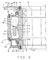
- FIG. 3 shows an alternative embodiment, the present invention. This embodiment is the same as the previous embodiment with the exception of the configuration of the bottom closure ring and the method of installing the present invention into a dragline excavating machine.
- the bottom closure ring 8A of the alternative embodiment comprises a washer 35A and a ring 37A in a welded assembly. It will be appreciated that other configurations of the bottom closure ring 8 are also acceptable provided that the configuration contacts the annular surface 40 of lower seal wear ring 6 and the gap between the bottom closure seal ring 8 and the surface of the seal carrier 10 resists the entrance of debris and contamination through the gap.
- the alternative embodiment also incorporates a design wherein the upper closure ring 7 and the upper seal wear ring 5 have matching threads which allow the upper closure ring 7 to be removed from the upper seal wear ring 5 by unscrewing the upper closure ring 7 from the upper seal wear ring 5.
- the upper closure ring 7 can also be tack welded to the upper seal wear ring 5 for a semi-permanent between the components. When a need to remove the upper closure ring 7 arises, the tack welds can be ground off the upper closure ring can be unscrewed from the upper seal wear ring 5.
- FIG. 3 also shows two annular protrusions 50, one on the lower seal wear ring 6 and one on the upper seal wear ring 5.
- the annular protrusions 50 assists in guarding against the entrance of contaminants into the bearing assembly A and also act as a locator for placement of the lower closure ring 8A on the lower seal ring 6 and for the upper closure ring 7 on the upper seal wear ring 5.
- FIG. 3 also shows a plurality of fasteners 52.
- the plurality of fasteners 52 are used to fasten the two seal carriers 10 to the outer ring 2.
- two annular beveled surfaces 51 which are located on the inner ring 1. The two annular beveled surfaces 51 assist in the installation of the bearing assembly A onto the dragline shaft 16.
Landscapes
- Engineering & Computer Science (AREA)
- General Engineering & Computer Science (AREA)
- Mechanical Engineering (AREA)
- Rolling Contact Bearings (AREA)
- Component Parts Of Construction Machinery (AREA)
Claims (19)
- Abgedichtetes Pendelrollenlager für eine Kratzbagger-Schwenkwelle an einer Kratzbaggeraushubmaschine, mit einem Außenring (2), einem Innenring (1) mit einer zentralen Bohrung, die an die Größe einer Kratzbagger-Schwenkwelle angepasst ist, einer ersten Mehrzahl von sphärischen Wälzkörpern (3A) und einer zweiten Mehrzahl von sphärischen Wälzkörpern (3B), die jeweils zwischen dem Innenring und dem Außenring angeordnet ist, einem oberen Dichtungstragring (5), einem unteren Dichtungstragring (6), einem oberen Verschlussring (7), einem unteren Verschlussring (8), mindestens einer Kontaktlippendichtung (9) und mindestens einem Kontaktlippendichtungsträger (10).
- Abgedichtetes Pendelrollenlager nach Anspruch 1, dadurch gekennzeichnet, dass sowohl der Innenring (1) als auch der Außenring (2) eine erste geneigte Lagerfläche (11, 13) und eine zweite geneigte Lagerfläche (12, 14) aufweisen, derart dass die erste geneigte Lagerfläche im Abstand von und entgegengesetzt geneigt zu der zweiten geneigten Lagerfläche angeordnet ist, und dass sowohl die ersten als auch die zweiten Lagerflächen eine Krümmung aufweisen, die der Krümmung der ersten und zweiten Mehrzahl von sphärischen Wälzkörpern (3A, 3B) entspricht.
- Abgedichtetes Pendelrollenlager nach Anspruch 2, dadurch gekennzeichnet, dass die erste Mehrzahl sphärischer Wälzkörper (3A) in Kontakt mit den ersten geneigten Lagerflächen (11, 13) steht und auf diesen abrollt und dass die zweite Mehrzahl sphärischer Wälzkörper (12, 14) in Kontakt mit den zweiten geneigten Lagerflächen (12, 14) steht und auf diesen abrollt.
- Abgedichtetes Pendelrollenlager nach Anspruch 3, dadurch gekennzeichnet, dass die erste Mehrzahl sphärischer Wälzkörper (3A) und die zweite Mehrzahl sphärischer Wälzkörper (3B) durch einen Käfig (4) im Abstand voneinander gehalten werden.
- Abgedichtetes Pendelrollenlager nach Anspruch 4, dadurch gekennzeichnet, dass zwischen dem unteren Dichtungstragring (8) und dem Innenring (1) sowie zwischen dem oberen Dichtungstragring (5) und dem Innenring (1) ein rastender Eingriff besteht.
- Abgedichtetes Pendelrollenlager nach Anspruch 5, dadurch gekennzeichnet, dass weiterhin ein erster Rastversatz (17) in einer vorderen Stirnseite (18) des Innenrings (1) vorgesehen ist, wobei der erste Rastversatz (17) derart angeordnet und ausgebildet ist, dass er in eine erste Rastschulter (20) an dem oberen Dichtungstragring (5) eingreift und einrastet.
- Abgedichtetes Pendelrollenlager nach Anspruch 6, dadurch gekennzeichnet, dass weiterhin ein zweiter Rastversatz (17) in einer rückwärtigen Stirnseite (19) des Innenrings (1) vorgesehen ist, wobei der erste Rastversatz (17) derart angeordnet und ausgebildet ist, dass er in eine zweite Rastschulter (20) an dem unteren Dichtungstragring (6) eingreift und einrastet.
- Abgedichtetes Pendelrollenlager nach Anspruch 7, dadurch gekennzeichnet, dass jede der ersten und der zweiten Rastschultern (20) eine ringförmige Lippe (21), einen ersten Versatz (22), eine erste ringförmige Nut (23), eine erste ringförmige Fläche (24) und eine erste Versatzfläche (25) umfassen.
- Abgedichtetes Pendelrollenlager nach Anspruch 8, dadurch gekennzeichnet, dass jede der ersten und der zweiten Rastversätze (17) eine zweite ringförmige Lippe (26), einen zweiten Versatz (27), eine zweite ringförmige Nut (28), eine zweite Versatzfläche (29) und eine vordere Stirnfläche (18) oder rückwärtige Stirnfläche (19) umfassen.
- Abgedichtetes Pendelrollenlager nach Anspruch 9, dadurch gekennzeichnet, dass zwischen dem oberen Dichtungstragring (5) und dem Innenring (1) sowie dem unteren Dichtungstragring (6) und dem Innenring (1) ein Presssitz besteht.
- Abgedichtetes Pendelrollenlager nach Anspruch 10, dadurch gekennzeichnet, dass sowohl der untere Dichtungstragring (6) als auch der obere Dichtungssitzring (5) eine Dichtungstragfläche (30) aufweist.
- Abgedichtetes Pendelrollenlager nach Anspruch 11, dadurch gekennzeichnet, dass die der mindestens eine Kontaktlippendichtungsträger (10) an dem Außenring (2) befestigt ist.
- Abgedichtetes Pendelrollenlager nach Anspruch 12, dadurch gekennzeichnet, dass der Außenring (2) eine vordere Stirnseite (31) und eine rückwärtige Stirnseite (32) aufweist und dass der mindestens eine Kontaktlippendichtungsträger (10) an der vorderen Stirnseite (31) des Außenrings befestigt ist und ein weiterer mindestens ein Kontaktlippendichtungsträger (10) an der rückwärtigen Stirnseite (32) des Außenrings befestigt ist.
- Abgedichtetes Pendelrollenlager nach Anspruch 13, dadurch gekennzeichnet, dass weiterhin mindestens eine Kontaktlippendichtung (9) vorgesehen ist, die entweder zwischen dem mindestens einen Kontaktlippendichtungsträger (10) und der vorderen Stirnseite (31) oder der rückwärtigen Stirnseite (32) des Außenrings angeordnet ist.
- Abgedichtetes Pendelrollenlager nach Anspruch 14, dadurch gekennzeichnet, dass die mindestens eine Kontaktlippendichtung (9) eine Lippe (9A) und ein Gehäuse aufweist, die die Kontaktlippendichtung (9) teilweise umschließen.
- Abgedichtetes Pendelrollenlager nach Anspruch 15, dadurch gekennzeichnet, dass zwei Kontaktlippendichtungen (9) vorgesehen sind, von denen die eine zwischen einem ersten Kontaktlippendichtungsträger (10) und der Tragfläche (30) des oberen Dichtungstragrings (5) und von denen die andere zwischen einem zweiten Kontaktlippendichtungsträger (10) und der Tragfläche (30) des unteren Dichtungstragrings (6) angeordnet ist.
- Abgedichtetes Pendelrollenlager nach Anspruch 16, dadurch gekennzeichnet, dass die Kontaktlippendichtung (9) eine Außenfläche für eine stauchende Anlage an einer Innenfläche des Dichtungsträgers (10) aufweist und eine Innenlippe für die Anlage an der Tragfläche (30) entweder des oberen Dichtungstragrings (5) oder des unteren Dichtungstragrings (6).
- Abgedichtetes Pendelrollenlager nach Anspruch 17, dadurch gekennzeichnet, dass eine Endspitze einer jeden der zwei Kontaktlippendichtungen (9) im Wesentlichen in Richtung der Längsmittellinie des Innenrings (1) weist.
- Abgedichtetes Pendelrollenlager nach Anspruch 17, dadurch gekennzeichnet, dass die Endspitze der Innenlippe, die an der Tragfläche (30) des oberen Dichtungstragrings (5) anliegt, im Wesentlichen weg von der Längsmittellinie des Innenrings (1) weist, und dass die Endspitze der Innenlippe, die an der Tragfläche (30) des unteren Dichtungstragrings (6) anliegt, im Wesentlichen zu der Längsmittellinie des Innenrings (1) hin weist.
Applications Claiming Priority (3)
| Application Number | Priority Date | Filing Date | Title |
|---|---|---|---|
| US37486602P | 2002-04-23 | 2002-04-23 | |
| US374866P | 2002-04-23 | ||
| PCT/US2003/012574 WO2003091587A1 (en) | 2002-04-23 | 2003-04-22 | Sealed spherical roller bearing for dragline swing shaft |
Publications (2)
| Publication Number | Publication Date |
|---|---|
| EP1497569A1 EP1497569A1 (de) | 2005-01-19 |
| EP1497569B1 true EP1497569B1 (de) | 2006-07-05 |
Family
ID=29270557
Family Applications (1)
| Application Number | Title | Priority Date | Filing Date |
|---|---|---|---|
| EP03733877A Expired - Lifetime EP1497569B1 (de) | 2002-04-23 | 2003-04-22 | Abgedichtetes pendelrollenlager für kratzbagger-schwenkwelle |
Country Status (6)
| Country | Link |
|---|---|
| US (1) | US6814494B2 (de) |
| EP (1) | EP1497569B1 (de) |
| JP (1) | JP4460309B2 (de) |
| AU (1) | AU2003239161A1 (de) |
| DE (1) | DE60306638T2 (de) |
| WO (1) | WO2003091587A1 (de) |
Families Citing this family (22)
| Publication number | Priority date | Publication date | Assignee | Title |
|---|---|---|---|---|
| EP1705392B2 (de) | 2003-11-18 | 2016-08-31 | NTN Corporation | Zweireihiges, selbstausrichtendes rollenlager und vorrichtung zur abstützung der hauptwelle eines windturbinengenerators |
| US7922396B2 (en) * | 2004-09-21 | 2011-04-12 | Ntn Corporation | Double row self-aligning roller bearing and main shaft support structure of wind power generator |
| US7523912B1 (en) * | 2004-12-17 | 2009-04-28 | Pelco Products, Inc. | Pivot base assembly for traffic pole |
| DE112005003424T5 (de) * | 2005-01-25 | 2007-12-13 | Ntn Corp. | Tragkonstruktion für ein Schrägzahnrad, Drehzahlerhöhungsgetriebe für einen Windkraftgenerator, und Tragkonstruktion für eine vertikale Welle |
| DE102007047527A1 (de) * | 2007-10-04 | 2009-04-09 | Schaeffler Kg | Radialwälzlager, insbesondere zweireihiges Schrägwälzlager |
| CN102138015A (zh) * | 2008-08-27 | 2011-07-27 | Skf公司 | 用于船舱推进系统的轴承 |
| DE102009014922A1 (de) * | 2009-03-25 | 2010-09-30 | Ab Skf | Fettgeschmiertes zweireihiges Wälzlager und Lagersystem mit einem derartigen Wälzlager und einer Schmiervorrichtung |
| DE102010051230A1 (de) * | 2010-11-12 | 2012-05-16 | Schaeffler Technologies Gmbh & Co. Kg | Abgedichtetes Wälzlager |
| DE102011003513A1 (de) * | 2011-02-02 | 2012-08-02 | Aktiebolaget Skf | Wälzlager |
| DE102011075548B4 (de) * | 2011-05-10 | 2015-12-17 | Schaeffler Technologies AG & Co. KG | Lager mit einer Energieerfassungseinheit, insbesondere Pendelrollen-Lager zur Lagerung einer Walze |
| DE102011078840A1 (de) | 2011-07-08 | 2013-01-10 | Schaeffler Technologies AG & Co. KG | Pendelrollenlager mit Dichtungsanordnung sowie Flossenstabilisator mit dem Pendelrollenlager |
| DE102012202592A1 (de) | 2012-02-21 | 2013-08-22 | Schaeffler Technologies AG & Co. KG | Wälzlager |
| EP2871377B1 (de) * | 2013-11-07 | 2017-01-25 | Aktiebolaget SKF | Lagereinheit für Strömungsmaschinenanwendung |
| DE102014219700A1 (de) * | 2014-09-29 | 2016-03-31 | Aktiebolaget Skf | Dichtung bei einem Lager und Verfahren für einen verschleißmindernden Betrieb einer Dichtung bei einem Lager |
| US9732793B2 (en) * | 2015-04-09 | 2017-08-15 | Aktiebolaget Skf | Bearing and bearing arrangement |
| US9850942B2 (en) * | 2015-04-09 | 2017-12-26 | Aktiebolaget Skf | Bearing and bearing arrangement |
| US9797440B2 (en) * | 2015-04-09 | 2017-10-24 | Aktiebolaget Skf | Bearing |
| JP2018179078A (ja) * | 2017-04-07 | 2018-11-15 | 株式会社ジェイテクト | 自動調心ころ軸受 |
| DE102019201353A1 (de) * | 2019-02-01 | 2020-08-06 | Horsch Maschinen Gmbh | Lagereinheit und landwirtschaftliche Maschine mit einer solchen Lagereinheit |
| DE102020118645B4 (de) | 2020-07-15 | 2022-02-17 | Schaeffler Technologies AG & Co. KG | Lagerring mit Dichtscheibe |
| IT202000021259A1 (it) * | 2020-09-08 | 2022-03-08 | Skf Ab | Tenuta a cassetta per uso in ambienti estremi |
| US20250179763A1 (en) * | 2023-11-30 | 2025-06-05 | Caterpillar Global Mining Llc | Bearing assembly for driveshafts of draglines |
Family Cites Families (5)
| Publication number | Priority date | Publication date | Assignee | Title |
|---|---|---|---|---|
| US3957319A (en) * | 1975-01-29 | 1976-05-18 | Reliance Electric Company | Pillow block and bearing assembly |
| SE450851B (sv) * | 1986-01-24 | 1987-08-03 | Skf Mekanprodukter Ab | Anordning for montering av ett lager innefattande tetningar |
| US5017025A (en) * | 1990-04-05 | 1991-05-21 | The Timken Company | Bearing assembly for a shaft journal |
| US5104239A (en) | 1991-03-06 | 1992-04-14 | Sague John E | In situ replaceable bearing |
| US5462367A (en) | 1994-08-18 | 1995-10-31 | The Timken Company | Compact bearing and stiffened journal |
-
2003
- 2003-04-22 WO PCT/US2003/012574 patent/WO2003091587A1/en not_active Ceased
- 2003-04-22 EP EP03733877A patent/EP1497569B1/de not_active Expired - Lifetime
- 2003-04-22 DE DE60306638T patent/DE60306638T2/de not_active Expired - Lifetime
- 2003-04-22 US US10/420,382 patent/US6814494B2/en not_active Expired - Lifetime
- 2003-04-22 AU AU2003239161A patent/AU2003239161A1/en not_active Abandoned
- 2003-04-22 JP JP2003588095A patent/JP4460309B2/ja not_active Expired - Fee Related
Also Published As
| Publication number | Publication date |
|---|---|
| JP4460309B2 (ja) | 2010-05-12 |
| US6814494B2 (en) | 2004-11-09 |
| EP1497569A1 (de) | 2005-01-19 |
| JP2005524030A (ja) | 2005-08-11 |
| AU2003239161A1 (en) | 2003-11-10 |
| DE60306638T2 (de) | 2007-06-21 |
| DE60306638D1 (de) | 2006-08-17 |
| WO2003091587A1 (en) | 2003-11-06 |
| US20030198416A1 (en) | 2003-10-23 |
Similar Documents
| Publication | Publication Date | Title |
|---|---|---|
| EP1497569B1 (de) | Abgedichtetes pendelrollenlager für kratzbagger-schwenkwelle | |
| EP2452090B1 (de) | Selbstausrichtende und wartungsfreie trageeinheit für landwirtschaftliche anwendungen | |
| EP0304160B1 (de) | Dichtung | |
| US20100096196A1 (en) | Track roller assembly and machine using same | |
| EP2304255B1 (de) | Schwenklagersystem | |
| US4810233A (en) | Interlocking universal joint seal assembly | |
| US5904356A (en) | Labyrinth seal with contaminant purging passageway for bearing housings | |
| US5104239A (en) | In situ replaceable bearing | |
| WO2010008972A8 (en) | Self-lubricated track roller assembly and machine using same | |
| US8075068B2 (en) | Track roller assembly and machine using same | |
| US4916750A (en) | Sealed double row spherical roller bearing | |
| US4244588A (en) | Shear seal assembly | |
| US10859118B2 (en) | Slewing roller bearing with at least two rows of roller elements | |
| US5062720A (en) | Replacement bearing for worn shafts | |
| CN113811696B (zh) | 分体式止推轴承壳体 | |
| US4339161A (en) | Bearing seal for a drill head assembly | |
| CN114658766A (zh) | 具有可拆卸密封模块的轴承 | |
| CN209818518U (zh) | 螺栓型圆柱滚子滚轮 | |
| US8388230B2 (en) | Seal guard | |
| US2295771A (en) | Protective covering for bearings | |
| US20230083042A1 (en) | Locking assembly for a shroud for a ground engaging tool | |
| US20260055792A1 (en) | Affirmatively retained self-sealing bearing cap | |
| US12523149B2 (en) | Cutting-ring assembly | |
| CN219242471U (zh) | 一种轴承座密封加强装置 | |
| US12049923B2 (en) | Cutting-ring assembly |
Legal Events
| Date | Code | Title | Description |
|---|---|---|---|
| PUAI | Public reference made under article 153(3) epc to a published international application that has entered the european phase |
Free format text: ORIGINAL CODE: 0009012 |
|
| 17P | Request for examination filed |
Effective date: 20041008 |
|
| AK | Designated contracting states |
Kind code of ref document: A1 Designated state(s): AT BE BG CH CY CZ DE DK EE ES FI FR GB GR HU IE IT LI LU MC NL PT RO SE SI SK TR |
|
| AX | Request for extension of the european patent |
Extension state: AL LT LV MK |
|
| 17Q | First examination report despatched |
Effective date: 20050223 |
|
| GRAP | Despatch of communication of intention to grant a patent |
Free format text: ORIGINAL CODE: EPIDOSNIGR1 |
|
| GRAS | Grant fee paid |
Free format text: ORIGINAL CODE: EPIDOSNIGR3 |
|
| GRAA | (expected) grant |
Free format text: ORIGINAL CODE: 0009210 |
|
| AK | Designated contracting states |
Kind code of ref document: B1 Designated state(s): DE FR GB SE |
|
| REG | Reference to a national code |
Ref country code: GB Ref legal event code: FG4D |
|
| REF | Corresponds to: |
Ref document number: 60306638 Country of ref document: DE Date of ref document: 20060817 Kind code of ref document: P |
|
| REG | Reference to a national code |
Ref country code: SE Ref legal event code: TRGR |
|
| ET | Fr: translation filed | ||
| PGFP | Annual fee paid to national office [announced via postgrant information from national office to epo] |
Ref country code: GB Payment date: 20070315 Year of fee payment: 5 |
|
| PLBE | No opposition filed within time limit |
Free format text: ORIGINAL CODE: 0009261 |
|
| STAA | Information on the status of an ep patent application or granted ep patent |
Free format text: STATUS: NO OPPOSITION FILED WITHIN TIME LIMIT |
|
| 26N | No opposition filed |
Effective date: 20070410 |
|
| PGFP | Annual fee paid to national office [announced via postgrant information from national office to epo] |
Ref country code: FR Payment date: 20070312 Year of fee payment: 5 |
|
| GBPC | Gb: european patent ceased through non-payment of renewal fee |
Effective date: 20080422 |
|
| REG | Reference to a national code |
Ref country code: FR Ref legal event code: ST Effective date: 20081231 |
|
| PG25 | Lapsed in a contracting state [announced via postgrant information from national office to epo] |
Ref country code: FR Free format text: LAPSE BECAUSE OF NON-PAYMENT OF DUE FEES Effective date: 20080430 |
|
| PG25 | Lapsed in a contracting state [announced via postgrant information from national office to epo] |
Ref country code: GB Free format text: LAPSE BECAUSE OF NON-PAYMENT OF DUE FEES Effective date: 20080422 |
|
| PGFP | Annual fee paid to national office [announced via postgrant information from national office to epo] |
Ref country code: SE Payment date: 20120418 Year of fee payment: 10 |
|
| REG | Reference to a national code |
Ref country code: SE Ref legal event code: EUG |
|
| PG25 | Lapsed in a contracting state [announced via postgrant information from national office to epo] |
Ref country code: SE Free format text: LAPSE BECAUSE OF NON-PAYMENT OF DUE FEES Effective date: 20130423 |
|
| PGFP | Annual fee paid to national office [announced via postgrant information from national office to epo] |
Ref country code: DE Payment date: 20160421 Year of fee payment: 14 |
|
| REG | Reference to a national code |
Ref country code: DE Ref legal event code: R119 Ref document number: 60306638 Country of ref document: DE |
|
| PG25 | Lapsed in a contracting state [announced via postgrant information from national office to epo] |
Ref country code: DE Free format text: LAPSE BECAUSE OF NON-PAYMENT OF DUE FEES Effective date: 20171103 |