EP1496779B1 - Automated grill - Google Patents
Automated grill Download PDFInfo
- Publication number
- EP1496779B1 EP1496779B1 EP03719814A EP03719814A EP1496779B1 EP 1496779 B1 EP1496779 B1 EP 1496779B1 EP 03719814 A EP03719814 A EP 03719814A EP 03719814 A EP03719814 A EP 03719814A EP 1496779 B1 EP1496779 B1 EP 1496779B1
- Authority
- EP
- European Patent Office
- Prior art keywords
- item
- grilling
- component
- food
- recited
- Prior art date
- Legal status (The legal status is an assumption and is not a legal conclusion. Google has not performed a legal analysis and makes no representation as to the accuracy of the status listed.)
- Expired - Lifetime
Links
- 235000013305 food Nutrition 0.000 claims description 114
- 230000004044 response Effects 0.000 claims description 9
- 238000000034 method Methods 0.000 claims description 3
- 229910001374 Invar Inorganic materials 0.000 description 6
- 235000013611 frozen food Nutrition 0.000 description 5
- 230000005355 Hall effect Effects 0.000 description 4
- 230000008901 benefit Effects 0.000 description 3
- XEEYBQQBJWHFJM-UHFFFAOYSA-N Iron Chemical compound [Fe] XEEYBQQBJWHFJM-UHFFFAOYSA-N 0.000 description 2
- PXHVJJICTQNCMI-UHFFFAOYSA-N Nickel Chemical compound [Ni] PXHVJJICTQNCMI-UHFFFAOYSA-N 0.000 description 2
- 235000014676 Phragmites communis Nutrition 0.000 description 2
- 230000008859 change Effects 0.000 description 2
- 238000010586 diagram Methods 0.000 description 2
- 235000015220 hamburgers Nutrition 0.000 description 2
- 239000000463 material Substances 0.000 description 2
- 239000004278 EU approved seasoning Substances 0.000 description 1
- 239000004809 Teflon Substances 0.000 description 1
- 239000011248 coating agent Substances 0.000 description 1
- 238000000576 coating method Methods 0.000 description 1
- 238000010411 cooking Methods 0.000 description 1
- 238000001816 cooling Methods 0.000 description 1
- 230000003247 decreasing effect Effects 0.000 description 1
- 238000006073 displacement reaction Methods 0.000 description 1
- 235000011194 food seasoning agent Nutrition 0.000 description 1
- 239000004519 grease Substances 0.000 description 1
- 230000001939 inductive effect Effects 0.000 description 1
- 229910052742 iron Inorganic materials 0.000 description 1
- 239000002184 metal Substances 0.000 description 1
- 229910052751 metal Inorganic materials 0.000 description 1
- 238000012986 modification Methods 0.000 description 1
- 230000004048 modification Effects 0.000 description 1
- 238000012544 monitoring process Methods 0.000 description 1
- 229910052759 nickel Inorganic materials 0.000 description 1
- 235000013573 potato product Nutrition 0.000 description 1
- 230000008569 process Effects 0.000 description 1
- 150000003839 salts Chemical class 0.000 description 1
- 239000011573 trace mineral Substances 0.000 description 1
- 235000013619 trace mineral Nutrition 0.000 description 1
- 230000001960 triggered effect Effects 0.000 description 1
- 238000009423 ventilation Methods 0.000 description 1
Images





Classifications
-
- A—HUMAN NECESSITIES
- A47—FURNITURE; DOMESTIC ARTICLES OR APPLIANCES; COFFEE MILLS; SPICE MILLS; SUCTION CLEANERS IN GENERAL
- A47J—KITCHEN EQUIPMENT; COFFEE MILLS; SPICE MILLS; APPARATUS FOR MAKING BEVERAGES
- A47J37/00—Baking; Roasting; Grilling; Frying
- A47J37/04—Roasting apparatus with movably-mounted food supports or with movable heating implements; Spits
- A47J37/044—Roasting apparatus with movably-mounted food supports or with movable heating implements; Spits with conveyors moving in a horizontal or an inclined plane
-
- A—HUMAN NECESSITIES
- A47—FURNITURE; DOMESTIC ARTICLES OR APPLIANCES; COFFEE MILLS; SPICE MILLS; SUCTION CLEANERS IN GENERAL
- A47J—KITCHEN EQUIPMENT; COFFEE MILLS; SPICE MILLS; APPARATUS FOR MAKING BEVERAGES
- A47J37/00—Baking; Roasting; Grilling; Frying
- A47J37/12—Deep fat fryers, e.g. for frying fish or chips
- A47J37/1228—Automatic machines for frying and dispensing metered amounts of food
Definitions
- Grills or griddles are used to cook various foods, such as hamburgers.
- the sides of the food are grilled separately.
- the food is placed on a flat grill portion, grilling the side of the food that contacts the flat grill portion. After that side of the food is cooked, the food is manually flipped to allow cooking the opposite side. After the food is cooked, the food is manually removed from the grill for serving.
- Another prior grill employs a conveyor belt positioned over a heater.
- the food is manually placed on the conveyor belt by an operator and grilled while the conveyor belt passes over the heater.
- EP 455477 discloses a grilling structure in which a number of patties are deposited onto a horizontal grilling surface by a robot.
- a method for grilling food comprising the steps of leading said food into a freezer component; sending a signal; automatically transferring said food from said freezer component to a grilling component in response to said signa ; grilling said food in said grilling component; and automatically transferring said food but of said grilling component; wherein said grilling component is arranged such that good is grilled in a plane obliquely angled from the vertical.
- the freezer component includes a rotatable portion, a loading side and a feeding side. Two raiseable platforms are located in each of the loading side and the feeding side. Food is loaded into the freezer component by placing the food onto the platforms positioned in the loading side. The rotatable portion then rotates 180° to position the food-loaded platforms in the feeding side. The empty platforms now located in the loading side are loaded with additional food. When a signal is received, food in the feeding side is supplied to the loading device by alternately raising the two platforms holding the food. When the feeding side is empty and contains no more food, the rotatable portion rotates 180° in the reverse direction, positioning the recently food-loaded platforms in the feeding side and the empty platforms in the loading side.
- the carousel 30 includes a magnet 19.
- Opposing sensors 17a and 17b such as magnetic reed sensors, are positioned proximate to the carousel 30.
- a signal is sent to the motor 43 by the control 51 to stop rotation of the carousel 30.
- the carousel 30 is rotated 180° in the opposing direction and the sensor 17b detects the magnet 19, a signal is sent to the motor 43 by the control 51 to stop rotation of the carousel.
- the carousel 30 further includes a projection 46 to prevent over-rotation.
- an example grilling component 26 includes a pair of grilling structures 80a and 80b separated by a gap d.
- Each grilling structure 80a and 80b includes a heater 82a and 82b, a drive pulley 84a and 84b, and a non-drive pulley 86a and 86b.
- the heaters 82a and 82b are electric resistance heaters.
- a conveyor belt 92a and 92b is positioned around the grilling structures 80a and 80b. The heater 82a and 82b in one example grill is at a temperature of 400°F.
- the proportional sensor 326 determines if the edge 100a of the conveyor belt 92a has moved laterally by monitoring the resistance in the spring 330. If the edge 100a of the conveyor belt 92a moves in the direction E, the yoke 334 responsively compress the spring 330, increasing the resistance in the spring 330.
- the controller 102a receives a corresponding indication from the proportional sensor 326 and responsively sends a signal to the adjustment motor 90 to raise the end 104a of the non-drive pulley 86a and laterally adjust the conveyor belt 92a a proportional amount in the direction B.
Landscapes
- Engineering & Computer Science (AREA)
- Food Science & Technology (AREA)
- Baking, Grill, Roasting (AREA)
- Confectionery (AREA)
Description
- The present invention relates generally to an automated grill which transfers frozen food from a freezer component to a grilling component by an automated loading device in response to a signal.
- Grills or griddles are used to cook various foods, such as hamburgers. In one prior grill, the sides of the food are grilled separately. The food is placed on a flat grill portion, grilling the side of the food that contacts the flat grill portion. After that side of the food is cooked, the food is manually flipped to allow cooking the opposite side. After the food is cooked, the food is manually removed from the grill for serving.
- In another prior grill, both sides of the food are grilled simultaneously. After programming the type of food into a control unit, the food is placed on a lower grill portion. A platen having an upper grill portion is then lowered over the food, positioning the food between the upper and lower grill portions and grilling the food simultaneously on both sides. After lowering the platen, the distance between the upper and lower grill portions is automatically adjusted according to the type of food which is programmed into the control unit. After a predetermined amount of time has passed, the platen raises, and the food is manually removed from the grill.
- Another prior grill employs a conveyor belt positioned over a heater. The food is manually placed on the conveyor belt by an operator and grilled while the conveyor belt passes over the heater.
- There are several drawbacks to the grills of the prior art. For one, the food must be manually placed on and removed from the grill, requiring additional labor. If the food is not immediately removed from the grill, overcooking is possible.
-
WO 96/16584 -
EP 455477 - EP 406475 discloses an automatic vending machine for automatically preparing fried food.
- In accordance with the invention, from a first aspect, there is provided a n automated grill comprising: a freezer component for maintaining an item in a frozen condition; a grilling component for grilling said item; and a loading device to automatically transfer a selected amount said item from said freezer component to said grilling component responsive to a request for said selected amount, wherein said grilling component includes means obliquely angled from a vertical plane for grilling the item.
- From a second aspect there is provided a method for grilling food comprising the steps of leading said food into a freezer component; sending a signal; automatically transferring said food from said freezer component to a grilling component in response to said signa ; grilling said food in said grilling component; and automatically transferring said food but of said grilling component; wherein said grilling component is arranged such that good is grilled in a plane obliquely angled from the vertical.
- The automated grill of the present invention automatically transfers frozen food from a freezer component to a grilling component by an automatic loading device in response to a signal.
- The freezer component includes a rotatable portion, a loading side and a feeding side. Two raiseable platforms are located in each of the loading side and the feeding side. Food is loaded into the freezer component by placing the food onto the platforms positioned in the loading side. The rotatable portion then rotates 180° to position the food-loaded platforms in the feeding side. The empty platforms now located in the loading side are loaded with additional food. When a signal is received, food in the feeding side is supplied to the loading device by alternately raising the two platforms holding the food. When the feeding side is empty and contains no more food, the rotatable portion rotates 180° in the reverse direction, positioning the recently food-loaded platforms in the feeding side and the empty platforms in the loading side.
- The loading device includes a pair of feeders each having a cutout and a sensor. The cutout is located over the feeding side. When a sensor detects that food is positioned in the cutout, a motor slides the feeder out of the freezer component to remove the food from the freezer component for delivery to the grilling component. Alternatively, the loading device is a pivotal arm which pivots to slide the food out of the freezer component.
- The grilling component includes a pair of grilling structures supported at an oblique angle from the vertical. Each grilling structure includes a heater and a moveable conveyor belt positioned around the heater. As the food travels on the conveyor belts between the heaters, the food is cooked. Preferably, the conveyor belt is made of a non-stick coated Invar™. A lateral sensor positioned proximate to an edge of each of the conveyor belts detects and compensates for lateral movement of the conveyor belts. After the food exits the grilling structures, the food slides onto a heated holding area for serving.
- These and other features of the present invention will be best understood from the following specification and drawings.
- The various features and advantages of the invention will become apparent to those skilled in the art from the following detailed description of the currently preferred embodiment. The drawings that accompany the detailed description can be briefly described as follows:
- Figure 1A schematically illustrates a block style schematic diagram of the automated grill of the present invention;
- Figure 1B schematically illustrates a side view of the automated grill of the present invention;
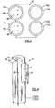
- Figure 2A schematically illustrates a cross sectional view of the freezer component of the automated grill of Figure 1B taken along line 2-2;
- Figure 2B schematically illustrates a top view of the carousel of the freezer component;
- Figure 3 schematically illustrates a cross sectional view of the freezer component of the automated grill of Figure 1B taken along line 3-3;
- Figure 4 schematically illustrates a perspective view of the exterior of the freezer component of the automated grill;
- Figure 5 schematically illustrates a top view of the loading device;
- Figure 6 schematically illustrates a side view of the loading device in a loading position;
- Figure 7 schematically illustrates a side view of the loading device in a delivery position;
- Figure 8 schematically illustrates a top view of an alternative example of a loading device;
- Figure 9 schematically illustrates a side view of the alternative example of the loading device of Figure 8;
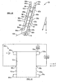
- Figure 10 schematically illustrates a front view of the grilling component;
- Figure 11 schematically illustrates a side view of the grilling component;
- Figure 12 schematically illustrates a side view of a second example of a lateral sensor;
- Figure 13 schematically illustrates a top view of a second example of a lateral sensor; and
- Figure 14 schematically illustrates a top view of a third example of a lateral sensor.
- Figure 1A illustrates a schematic block diagram of an
automated grill 20. Theautomated grill 20 includes afreezer component 22, agrilling component 26, and aloading device 24 which automatically transfers food from thefreezer component 22 to thegrilling component 26 in response to a signal. - Figure 1B illustrates an example automated
grill 20 designed according to the present invention.Frozen food items 52, such as frozen hamburger patties, are loaded in thefreezer component 22. Thefreezer component 22 includes arotatable portion 28 mounted on acarousel 30. Thefreezer component 22 further includes aloading side 32 and a feeding side 34. Anupper sensor 42 and alower sensor 44 are located proximate to the upper end and the lower end, respectively, of therotatable portion 28.
Thefreezer component 22 in one example uses forced air convection. In another example, the freezer component comprises 22 a cold wall freezer. Preferably, the temperature in thefreezer component 22 is between -18°C and -21°C. - As shown in Figure 2A, the example
rotatable portion 28 includes foursurfaces rotatable portion 28 is positioned as in Figure 1B, thesurfaces 36a and 36b are located in the feeding side 34, and thesurfaces loading side 32. Aplatform respective surfaces drive respective motor platforms - When the
platforms loading side 32 are in a loading position, theplatforms food items 52.Rods 41 located on the outer periphery of theplatforms food 52 from falling from theplatforms rotatable portion 28. After a desired number offood items 52 are loaded, thecarousel 30 rotates therotatable portion 28 180° in a first direction, positioning theplatforms food items 52 in the feeding side 34. The same motion moves theplatforms 38a and 38b to theloading side 32. Theplatforms 38a and 38b can then be loaded withmore food items 52. As shown in Figure 2B, thecarousel 30 includes amagnet 19. Opposingsensors carousel 30. When thecarousel 30 rotates 180° and thesensor 17a detects themagnet 19, a signal is sent to themotor 43 by thecontrol 51 to stop rotation of thecarousel 30. When thecarousel 30 is rotated 180° in the opposing direction and thesensor 17b detects themagnet 19, a signal is sent to themotor 43 by thecontrol 51 to stop rotation of the carousel.
Thecarousel 30 further includes aprojection 46 to prevent over-rotation.Stops 47 and 48 located in thefreezer compartment 22 prevent over-rotation of thecarousel 30 and tangling of wires (not illustrated). If thecarousel 30 over-rotates, theprojection 46 engages one of thestops 47 and 48, preventing further rotation of thecarousel 30. - Returning to Figure 1, when at least one of the
food items 52 is to be grilled, aninput 50 sends a signal to acontrol 51 which sends a signal to the desiredmotor respective platforms food item 52 in theloading device 24 for delivery to thegrilling component 26. As therotatable portion 28 has rotated 180°, theplatforms platforms 38a and 38b are located in theloading side 32. Thefood items 52 are alternately delivered from theplatforms loading device 24. For example, after theinput 50 sends a signal indicating a request to grill afood item 52,platform 38c rises to position afood item 52 in theloading device 24. When the next signal is received,platform 3 8d rises to position anotherfood item 52 in theloading device 24. A subsequent signal raises theplatform 38c, and so on.
Preferably, theinput 50 includes a POS (point of service) register. When afood item 52 is ordered by a customer, an operator inputs the order into the POS register. The POS register sends the signal to thecontrol 51, which responsively dispenses the desired number offood items 52. Alternatively, an operator inputs into theinput 50 the numbers offood items 52 that are to be delivered to thegrilling component 26 for grilling. - The
platforms food items 52 in the feeding area 34 are eventually transferred to thegrilling component 26 for grilling. When theupper sensor 42 senses that both of theplatforms platforms loading device 24 would have removed all of thefood items 52, the feeding side 34 is empty. Thecarousel 30 then rotates therotatable portion 28 180° in an opposing direction. If thecarousel 30 over-rotates, theprojection 46 engages the other stop 47 to prevent over-rotation. Asensor 49 monitors the position of thecarousel 30 and communicates to thecarousel 30 when to stop rotating. - Rotation in the opposition direction positions the
platforms 38a and 38b loaded with thefood items 52 in the feeding side 34, and theplatforms food items 52 in theloading side 32. During rotation, theplatforms loading side 32 lower so they are ready to receiveadditional food items 52. When thelower sensor 44 senses theplatforms automated grill 20 knows that theloading side 32 is ready for loading ofadditional food items 52. - Preferably, the
upper sensor 42 and thelower sensor 44 are magnetic reed switches and theplatforms upper sensor 42 orlower sensor 44 sense the magnet, thesensors platforms platforms - After all the
food items 52 are removed from the feeding side 34 of thefreezer component 22, theplatforms upper sensor 42 senses the magnet in theplatforms upper sensor 42 knows that theplatforms upper sensor 42 provides a signal to themotor 43 to rotate thecarousel 30 and to themotors empty platforms platforms platforms loading side 32. Once theplatforms loading side 32, thelower sensor 44 detects the magnets. Although magnetic sensors have been described, it is to be understood that other types ofsensors - As shown in Figure 3, a
ring rotatable portion 28 in each of the respective foursurfaces rings inner aperture food items 52. Therings food items 52 as theplatforms food items 52 into theloading device 24. In one example, therings several food items 52 at once. - Alternatively, the
freezer component 22 does not include acarousel 30 and a feeding side 34. Thefood items 52 are both loaded into thefreezer component 22 and transferred into theloading device 24 in theloading side 32. Thefood items 52 can be loaded into theloading side 32 in a cartridge which contains a plurality offood items 52 to expedite the loading process. - As shown in Figure 4, the
freezer component 22 is enclosed by ahousing 58 including adoor 60. When thedoor 60 is opened, an operator can access theloading side 32 of thefreezer component 22 through an access opening 62 during operation. Theexample freezer component 22 further includes aninterlock 64 which prevents rotation of therotatable portion 28 when thedoor 60 is opened. - The
food items 52 are transferred from the feeding side 34 of thefreezer component 22 to thegrilling component 26 by theloading device 24. An example loading device is schematically illustrated in Figures 5 to 7. For the below description, theplatforms side 24, although it is to be understood that theplatforms 38a and 38b can also be located in the feedingside 24 when therotatable portion 28 is rotated. The illustratedloading device 24 includes a pair offeeders 66 each positioned above each of theplatforms motor 70. Eachfeeder 66 includes acutout 68 extending partially through the height h of thefeeder 66. Preferably, thecutout 68 is circular and the same shape as thefood items 52. Asensor 72 is located at theupper surface 74 of each of thecutout 68. - Figure 6 illustrates one of the
feeders 66 in the loading position. One of theplatforms food item 52 in thecutout 68. When thesensor 72 detects that afood item 52 is located in thecutout 68, themotor 70 moves thefeeder 66 in direction A (i.e., to the left in Figure 6) and out of the front slot 76 (shown in Figure 4) to the delivery position, as shown in Figure 7. Thefood item 52 drops from thecutout 68 and slides down the ramp 78 (shown in Figure 1) into thegrilling component 26. Themotor 70 then movesfeeder 66 in direction B (i.e., to the right in Figure 7) to the loading position. Themotor 70 provides enough force to separate frozenfood items 52 in case thefood items 52 are frozen together. This repeats for alternatingfeeders 66 as the alternatingplatforms 38a and 38d rise to supply thefood items 52. - During high demand times, both
platforms 38a and 38b in the rotatable portion 34 can rise simultaneously. Thesensors 72 in both of thefeeders 66 are triggered at once, and bothfeeders 66 slide in direction A to the delivery position, allowing for twofood items 52 to be delivered to thegrilling component 26 at once. - Figures 8 and 9 illustrate an alternative example of the
loading device 224 including anarm 226 pivotal aboutpivot point 228. Thearm 226 includes apusher 230 having anangled edge 232. - When a
sensor 238 proximate to thearm 226 detects that afood item 52 is located proximate to theloading device 224, thearm 226 rotates about thepivot point 228. Theangled edge 232 engages thefood item 52, thepusher 230 sliding under thefood item 52 and breaking apart thefood items 52 if frozen together. Thebeam 236 over thearm 226 provides an upper boundary for thefood item 52 as thepusher 230 slides under thefood item 52. As thearm 226 continues to pivot, thefood item 52 is pushed out of the front slot 76 (shown in Figure 4) and down theramp 78 for grilling. - After sliding down the
ramp 78 from theloading device 24, thefood items 52 are grilled by thegrilling component 26. As schematically shown in Figure 10, anexample grilling component 26 includes a pair ofgrilling structures grilling structure heater drive pulley non-drive pulley 86a and 86b. In one example, theheaters conveyor belt grilling structures heater respective drive motors 88a and 88b to move theconveyor belts heaters non-drive pulleys 86a and 86b are each controlled by arespective adjustment motor drive controller 94 provides a control signal to thedrive motors 88a and 88b to synchronize the speed of theconveyor belts - The
food items 52 are grilled by passing thefood items 52 in the gap d while food traveling between theconveyor belts food items 52 are squeezed within the gap d, thefood items 52 do not slip between theconveyor belts 92a and 92. Theheater conveyor belts food items 52. - The
grilling structures - The
conveyor belts conveyor belts - The distance d between the grilling
structures members 96. The distance d varies along the length of thegrilling structures food items 52. By varies, it is meant that the distance d can be larger at different positions along the length of thegrilling structures grilling structures members 96 to allow for grilling different sizes of thefood items 52 for a given automatedgrill 20. - During operation of the
automated grill 20, it may be possible for theconveyor belts pulleys lateral sensors respective edges conveyor belts lateral sensor 99a and 99b is positioned proximate to therespective edges 101 a and 101b of theconveyor belts lateral sensors edges lateral sensors adjustment motor 90a to move an end 104a of the non-drive pulley 86a to adjust for the lateral movement. Preferably, thelateral sensor 98a in one example is a non-contacting inductive proximity sensor. Theadjustment motor 90a rotates to move the non-drive pulley 86a to return theconveyor belt 92a to the desired position. - If the
conveyor belt 92a has moved in the direction E (i.e., to the right in Figure 11), thelateral sensor 99a does not sense theedge 101a of theconveyor belt 92a. The controller 102a then sends a signal to theadjustment motor 90a which rotates to raise the end 104a of the non-drive pulley 86a and move theconveyor belt 92a in the direction F (i.e., to the direction left in Figure 11). After a predetermined amount of time, thelateral sensor 99a again tries to detect the presence of theedge 101a of theconveyor belt 92a. If theedge 101a of theconveyor belt 92a is detected, no further adjustment is needed. If theedge 101a of theconveyor belt 92a is not detected, theadjustment motor 90a rotates again to raise the end 104a of the non-drive pulley 86a to again move theconveyor belt 92a in the direction F. This is repeated until theconveyor belt 92a is detected by thesensor 99a. - Alternatively, if the
conveyor belt 92a has moved in the direction F (i.e., to the left in Figure 11), thelateral sensor 98a does not sense theedge 100a of theconveyor belt 92a. The controller 102a then sends a signal to theadjustment motor 90a which rotates to lower the end 104a of the non-drive pulley 86a and move theconveyor belt 92a in the direction E (i.e., to the direction right in Figure 11). After a predetermined amount of time, thelateral sensor 98a again tries to detect the presence of theedge 100a of theconveyor belt 92a. If theedge 100a of theconveyor belt 92a is detected, no further adjustment is needed. If theedge 100a of theconveyor belt 92a is not detected, theadjustment motor 90a rotates again to lower the end 104a of the non-drive pulley 86a to again move theconveyor belt 92a in the direction E. This is repeated until theedge 100a of theconveyor belt 92a is detected by thesensor 98a in the desired location. Although twosensors conveyor belt sensors - Figures 12 and 13 illustrate a second example of a
lateral sensor 324. Thelateral sensor 324 includes aproportional sensor 326, such as a linear variable displacement transducer or a linear potentiometer, having ashaft 328. Aspring 330 is positioned between a pair ofwashers shaft 328 and provides resistance to ayoke 334. Arotatable wheel 336 having agroove 338 is secured to theyoke 334 by arod 340. In one example, therotatable wheel 336 is ½ inch in diameter and has a thickness of 1/8 inch to accommodate theconveyor belt groove 338 contacts theedge 100a of theconveyor belt 92a. - The
proportional sensor 326 determines if theedge 100a of theconveyor belt 92a has moved laterally by monitoring the resistance in thespring 330. If theedge 100a of theconveyor belt 92a moves in the direction E, theyoke 334 responsively compress thespring 330, increasing the resistance in thespring 330. The controller 102a receives a corresponding indication from theproportional sensor 326 and responsively sends a signal to the adjustment motor 90 to raise the end 104a of the non-drive pulley 86a and laterally adjust theconveyor belt 92a a proportional amount in the direction B. Alternatively, if theedge 100a of theconveyor belt 92a moves in the direction F, theyoke 334 responsively expands thespring 330, decreasing the resistance in thespring 330. The controller 102a receives a corresponding indicating from theproportional sensor 326 and responsively sends a signal to the adjustment motor 90 to lower the end 104a of the non-drive pulley 86a and laterally adjust theconveyor belt 92a a proportional amount in the direction A. - Alternatively, as shown in Figure 14, a
lateral sensor respective edges edges conveyor belt 92a are positioned in achannel 426a and 427a, respectively, in thelateral sensor edge 100a of theconveyor belt 92a moves laterally in the direction F away from the channel 426a, the Hall effect sensor 430a detects a change in themagnetic field 428a, indicating that theedge 100a of theconveyor belt 92a has moved laterally. Theconveyor belt 92a is laterally adjusted in the direction F by rotating theadjustment motor 90a in the manner described above. Alternatively, as theedge 101a of theconveyor belt 92a moves laterally in the direction E away from thechannel 427a, the Hall effect sensor 431a detects a change in themagnetic field 429a, indicating that theedge 101 a of theconveyor belt 92a has moved laterally. Theconveyor belt 92a is laterally adjusted in the direction F by rotating theadjustment motor 90a in the manner described above. Although not shown, it is to be understood that a lateral sensor including a Hall effect sensor (not shown) is positioned on theedges 100b and 101b of theconveyor belt 92b. - Returning to Figure 1, after exiting the
grilling component 26, eachfood item 52 slides down anexit ramp 106 and onto a holdingarea 108 for storage until removal for serving. Preferably, the holdingarea 108 consists of a plurality ofrollers 114. Aheater 110 is positioned over the holdingarea 108 to heat thefood items 52. Anautomatic seasoner 112 can also be positioned over the holdingarea 108 to dispense selected seasonings such as salt on thefood items 52 after grilling. - As shown in Figure 10, one example automated
grill 20 includes other features, such as agrease dripper 116 or a grill scraper to clean theconveyor belts hood 120 can also be placed above theautomated grill 20 to provide ventilation. Additionally, thefrozen food items 52 can be placed in thefreezer component 22 in cartridges which contain several items offood 52, reducing crew labor in loading. - There are several benefits and advantages provided by the automatic grill of the present invention that enhances the economizes associated with preparing the food items. As the food items are automatically loaded and removed from the automated grill, crew labor is reduced and safety is improved. The inventive automated grill of this invention also has a smaller footprint than the prior art grills, requiring less space. The inventive automated grill, including the stacked food items configuration, reduces the surface area of the food items exposed to the environment.
- Additionally, as the food items are grilled after operator input or POS input, the food items are grilled to order. As the automated grill is automated, improvements in the quality and consistency of the food items is possible. Finally, by angling the grilling structures, the food items are loaded closer to the grill inlet, exit closer to the point of use, and therefore reduces raw food dropping on the cooked food.
- The foregoing description is only exemplary of the principles of the invention. Many modifications and variations are possible in light of the above teachings. It is, therefore, to be understood that within the scope of the appended claims, the invention may be practiced otherwise than using the example embodiments which have been specifically described. For that reason the following claims should be studied to determine the true scope and content of this invention.
Claims (18)
- An automated grill (20) comprising:a freezer component (22) for maintaining an item (52) in a frozen condition;a grilling component (26) for grilling said item (52); anda loading device (24; 224) to automatically transfer a selected amount of said item (52) from said freezer component (22) to said grilling component (26) responsive to a request for said selected amount; wherein said grilling component (26) includes means obliquely angled from a vertical plane for grilling the item (52).
- The automated grill as recited in claim 1 wherein said freezer component (22) includes a moveable portion (28), a loading side (32) for loading said item (52) in said freezer component (22), a feeding side (34) for removal of said item (52) from said freezer component (22) in response to said request, and at least one platform (38) for supporting the item (52) in each of said loading side (32) and said feeding side (34) slidingly moveable along said moveable portion (28).
- The automated grill as recited in claim 2 wherein said item (52) is selectively stacked on said at least one platform (38a...38d) in said loading side (32) and said item (52) is delivered to said loading device (24) by raising said at least one platform (38a) in said feeding side (34) in response to said request.
- The automated grill as recited in claim 2 or 3 wherein said at least one platform (38a ...38d) in said feeding side (34) includes two platforms that alternately raising in response to said request.
- The automated grill as recited in any of claims 2 to 4 wherein said moveable portion (28) is mounted on a rotatable carousel (30), and rotation of said carousel (30) 180° transfers said at least one platform (38a ...38d) between said feeding side (34) and said loading side (32).
- The automated grill as recited in claim 5 wherein said freezer component (22) further includes a lower sensor (44) and an upper sensor (42), said carousel (30) rotating 180° responsive to said upper sensor (42) indicating that said at least one rotatable platform (38a ...38d) located in said feeding side (34) is above a first selected position, and said lower sensor (44) indicating when said at least one platform (38a ...38d) in said loading side (32) is below a second selected position.
- The automated grill as recited in any preceding claim wherein said loading device (24; 224) includes at least one moving device (66; 226) and an item sensor (72; 238), and said at least one moving device (66; 226) moves responsively when said item sensor (72; 238) senses said item (52).
- The automated grill as recited in claim 7 wherein said at least one moving device is a feeder (66) having an opening (68) located to receive said item (52) provided from one of said at least one platform (38a...38d) in said feeding side (34) in response to said request.
- The automated grill as recited in claim 8 wherein said feeder (66) slides from a loading position to a delivery position when said item sensor (72) detects that said item is located in said opening (68) of said feeder (66) to remove said (52) item from said freezer component (22).
- The automated grill as recited in claim 7 wherein said moving device comprises a pivotally supported arm (226) which pivots to slide said item out of said freezer component (22) when said item sensor (238) detects said item (52) is proximate to said pivotal arm (226).
- The automated grill as recited in any preceding claim further including a controller (51) associated with said automated grill, wherein said request comprises a signal sent by a POS device.
- The automated grill as recited in any preceding claim wherein said grilling component (26) includes a pair of grilling structures (80a, 80b) separated by a gap (d).
- The automated grill as recited in claim 12 wherein each of said pair of grilling structures (80a, 80b) includes a heater (82a, 82b) and a conveyor belt (92a, 92b), and said item (52) is grilled while traveling in said gap (d) between said pair of grill structures (80a, 80b) on said conveyor belts (92a, 92b).
- The automated grill as recited in claim 12 or 13 wherein said pair of grilling structures (80a, 80b) are angled approximately 5° from a vertical line.
- The automated grill as recited in claim 12, 13 or 14 wherein each of said pair of grill structures (80a, 80b) includes a drive pulley (84a, 84b) powered by a drive motor (88a, 88b) to drive said conveyor belts (92a, 92b), and a drive (94) provides a pulse to said drive motors (88a, 88b) to synchronize said drive motors (88a, 88b) and to move said conveyor belts (92a, 92b) at an equal speed.
- The automated grill as recited in any preceding claim further including a holding area (108), and wherein said grilled food slides onto said holding area (108) after exiting said grilling component (26).
- The automated grill as recited in claim 16 wherein said holding area (108) is heated.
- A method for grilling food comprising the steps ofloading said food into a freezer component (22);sending a signal;automatically transferring said food (52) from said freezer component (22) to a grilling component (26) in response to said signal;grilling said food (52) in said grilling component (26); andautomatically transferring said food out of said grilling component (26);wherein said grilling component (26) is arranged such that food is grilled in a plane obliquely angled from the vertical.
Applications Claiming Priority (3)
| Application Number | Priority Date | Filing Date | Title |
|---|---|---|---|
| US124629 | 2002-04-17 | ||
| US10/124,629 US7001626B2 (en) | 2002-04-17 | 2002-04-17 | Automated grill |
| PCT/US2003/011944 WO2003088793A1 (en) | 2002-04-17 | 2003-04-16 | Automated grill |
Publications (2)
| Publication Number | Publication Date |
|---|---|
| EP1496779A1 EP1496779A1 (en) | 2005-01-19 |
| EP1496779B1 true EP1496779B1 (en) | 2007-06-13 |
Family
ID=29214624
Family Applications (1)
| Application Number | Title | Priority Date | Filing Date |
|---|---|---|---|
| EP03719814A Expired - Lifetime EP1496779B1 (en) | 2002-04-17 | 2003-04-16 | Automated grill |
Country Status (7)
| Country | Link |
|---|---|
| US (2) | US7001626B2 (en) |
| EP (1) | EP1496779B1 (en) |
| JP (1) | JP4228215B2 (en) |
| CN (1) | CN1317993C (en) |
| AU (1) | AU2003223673B2 (en) |
| DE (1) | DE60314393T2 (en) |
| WO (1) | WO2003088793A1 (en) |
Families Citing this family (21)
| Publication number | Priority date | Publication date | Assignee | Title |
|---|---|---|---|---|
| US8276505B2 (en) * | 2004-02-18 | 2012-10-02 | David Benjamin Buehler | Food preparation system |
| US6998582B1 (en) | 2005-03-14 | 2006-02-14 | Hickory Industries, Inc. | Cooking apparatus |
| US7228989B2 (en) * | 2005-04-13 | 2007-06-12 | Delphi Technologies, Inc. | High efficiency beverage vending machine |
| US7878109B2 (en) * | 2006-04-28 | 2011-02-01 | Restaurant Technology, Inc. | Automated dual cooking surface grill |
| CA2788552C (en) * | 2006-04-26 | 2013-08-27 | Restaurant Technology, Inc. | Automated dual cooking surface grill and method |
| US8757052B2 (en) * | 2009-11-05 | 2014-06-24 | Ebip Holdings, Llc | Conveyor griddle system |
| US20120204733A1 (en) * | 2011-02-15 | 2012-08-16 | Gilbert Dennis | Cooking System |
| CN105007742B (en) * | 2013-01-11 | 2017-12-26 | 株式会社七洋制作所 | Baking device and baking box |
| WO2014150206A2 (en) | 2013-03-15 | 2014-09-25 | Carrier Commerical Refrigeration, Inc. | Automated cleaning of cooking apparatus |
| US20150118378A1 (en) * | 2013-10-28 | 2015-04-30 | Enodis Corporation | Vertical broiler |
| US10154762B2 (en) | 2015-05-07 | 2018-12-18 | Spyce Food Co. | Automated meal production system and apparatus |
| WO2017218564A1 (en) * | 2016-06-13 | 2017-12-21 | Henny Penny Corporation | Automated kitchen systems and methods including conveyor stock handling and delivery to cooking devices |
| US10264916B2 (en) | 2016-06-14 | 2019-04-23 | Vinay Shivaiah | Recipe driven kitchen automation of food preparation |
| IT201700043109A1 (en) * | 2017-04-19 | 2018-10-19 | Martina Lisa Castellano | EQUIPMENT FOR THE PREPARATION AND DISTRIBUTION OF FOOD PRODUCTS FROM OVEN, IN PARTICULAR PIZZAS |
| US20190059643A1 (en) * | 2017-08-22 | 2019-02-28 | Taylor Commercial Foodservice Inc. | Automated grill with conveyor and active compression |
| EP3788845A4 (en) | 2018-04-30 | 2022-04-20 | Spyce Food Co. | APPARATUS AND METHOD FOR ROBOTIC HEATING |
| CA3066299C (en) * | 2019-01-05 | 2022-04-26 | Traeger Pellet Grills, Llc | Pellet grills having pellet level detection systems and related methods |
| CA3230855C (en) | 2019-02-25 | 2026-08-04 | Taylor Commercial Foodservice, Llc | Automated food management system |
| US12446727B2 (en) | 2019-09-25 | 2025-10-21 | Marmon Foodservice Technologies, Inc. | Vertical heat transfer device |
| TWI777341B (en) * | 2020-12-29 | 2022-09-11 | 皇丞創新科技股份有限公司 | Automatic heating vending machine |
| KR102756159B1 (en) * | 2024-11-11 | 2025-01-21 | 주식회사 비욘드허니컴 | automatic grilling robot |
Family Cites Families (34)
| Publication number | Priority date | Publication date | Assignee | Title |
|---|---|---|---|---|
| JPS4920512A (en) | 1972-06-17 | 1974-02-23 | ||
| JPS6057115B2 (en) | 1978-10-16 | 1985-12-13 | 芝浦メカトロニクス株式会社 | vending machine |
| US4179985A (en) * | 1978-10-19 | 1979-12-25 | Npi Corporation | Sandwich cooking and assembling unit |
| JPS6034672U (en) | 1983-08-12 | 1985-03-09 | 株式会社 ユニ機器 | vending machine |
| DE3502816A1 (en) * | 1984-04-05 | 1985-10-17 | TEPRO-Präzisionstechnik GmbH, 7742 St Georgen | FOOD MACHINE |
| JPS62132034U (en) | 1986-02-07 | 1987-08-20 | ||
| US4660467A (en) * | 1986-02-10 | 1987-04-28 | Edna Waks | Food processing apparatus |
| JPS6311440U (en) | 1986-07-09 | 1988-01-25 | ||
| JPH0511221Y2 (en) | 1986-12-16 | 1993-03-19 | ||
| US5121677A (en) * | 1989-05-03 | 1992-06-16 | Edible Technology, Inc. | Pizza making and baking machine |
| FR2660836B2 (en) * | 1989-06-12 | 1992-08-28 | Grandi Rene | DEVICE FOR RESETTING IN TEMPERATURE AND FOR DISTRIBUTING MEALS SELECTED ACCORDING TO CHOICE. |
| JPH0719304B2 (en) | 1989-07-06 | 1995-03-06 | 東広島ゴルフ振興株式会社 | Automatic fly selling equipment |
| US5224415A (en) | 1989-12-29 | 1993-07-06 | Gas Research Institute | Frozen food storage and dispensing system |
| US5227597A (en) | 1990-02-16 | 1993-07-13 | Electric Power Research Institute | Rapid heating, uniform, highly efficient griddle |
| JPH04164414A (en) | 1990-03-02 | 1992-06-10 | Japan Small Corp | Automatic food baking apparatus |
| DE69101172T2 (en) | 1990-05-04 | 1994-07-21 | Restaurant Technology | Food preparation system and method. |
| AU9032491A (en) * | 1990-10-10 | 1992-05-20 | Gary W. Black Sr. | Apparatus for heating and dispensing food products |
| US5168795A (en) * | 1990-11-29 | 1992-12-08 | Higashi Hiroshima Golf Shinko Kabushiki Kaisha | Automatic food frying and vending system |
| US5044264A (en) | 1991-01-28 | 1991-09-03 | Forney Robert B | Cooking apparatus for producing grill stripes on cooked products |
| US5566856A (en) * | 1991-06-06 | 1996-10-22 | Norma Fallen | Hot food and frozen food vending machine |
| JPH0783696B2 (en) * | 1993-04-06 | 1995-09-13 | 株式会社共和工業所 | Hamburger cooking equipment |
| IT1265570B1 (en) * | 1993-07-27 | 1996-11-22 | Ivan Tocchet | AUTOMATIC FOOD DISTRIBUTOR ESPECIALLY FOR HOT FOODS SUCH AS TOAST - SANDWICHES - PIZZAS - BRIOSCHES |
| JPH0748034A (en) | 1993-08-03 | 1995-02-21 | Kyowa Kogyosho:Kk | Frozen stocker |
| US5452786A (en) | 1994-07-19 | 1995-09-26 | Rapistan Demag Corporation | High-speed paddle diverter |
| AU4258796A (en) * | 1994-11-30 | 1996-06-19 | Technolizenz Establishment | Grilling unit for grillable foodstuffs |
| ES2110904B1 (en) * | 1995-07-17 | 1998-10-01 | Montserrat Gibernau Antonio | PACKAGED FOOD PRODUCTS VENDING MACHINE. |
| US5802958A (en) | 1997-06-16 | 1998-09-08 | Hermansson; Alf E. | Cooking grill |
| SE513106C2 (en) | 1998-11-04 | 2000-07-10 | Svenska Mcdonalds Ab | Grill for cooking portions of food, preferably hamburgers, regulates speed of food through grill as function of food temperature after grilling in order to give desired temperature interval in food |
| DE19920493C2 (en) | 1999-05-05 | 2002-07-18 | Schott Glas | Accessories for ovens and dishes that can be used in them |
| CA2453323A1 (en) * | 2001-07-18 | 2003-01-30 | Irm, Llc | High throughput incubation devices |
| ATE363703T1 (en) * | 2002-02-21 | 2007-06-15 | Neemat Frem | DEVICE AND METHOD FOR AUTOMATICALLY DISPENSING SUPPLIES |
| US7055675B2 (en) | 2002-12-04 | 2006-06-06 | 3M Innovative Properties Company | Conveyor belt cleaning system |
| JP4164414B2 (en) | 2003-06-19 | 2008-10-15 | キヤノン株式会社 | Stage equipment |
| JP4920512B2 (en) | 2007-07-04 | 2012-04-18 | エルピーダメモリ株式会社 | Calibration circuit, semiconductor device including the same, and data processing system |
-
2002
- 2002-04-17 US US10/124,629 patent/US7001626B2/en not_active Expired - Fee Related
-
2003
- 2003-04-16 WO PCT/US2003/011944 patent/WO2003088793A1/en not_active Ceased
- 2003-04-16 JP JP2003585548A patent/JP4228215B2/en not_active Expired - Fee Related
- 2003-04-16 DE DE60314393T patent/DE60314393T2/en not_active Expired - Lifetime
- 2003-04-16 AU AU2003223673A patent/AU2003223673B2/en not_active Ceased
- 2003-04-16 CN CNB038087375A patent/CN1317993C/en not_active Expired - Fee Related
- 2003-04-16 EP EP03719814A patent/EP1496779B1/en not_active Expired - Lifetime
-
2005
- 2005-11-22 US US11/284,643 patent/US8234972B2/en not_active Expired - Fee Related
Also Published As
| Publication number | Publication date |
|---|---|
| US7001626B2 (en) | 2006-02-21 |
| WO2003088793B1 (en) | 2004-05-13 |
| US8234972B2 (en) | 2012-08-07 |
| CN1646048A (en) | 2005-07-27 |
| US20060073253A1 (en) | 2006-04-06 |
| CN1317993C (en) | 2007-05-30 |
| JP4228215B2 (en) | 2009-02-25 |
| US20030196558A1 (en) | 2003-10-23 |
| JP2005523055A (en) | 2005-08-04 |
| AU2003223673B9 (en) | 2003-11-03 |
| AU2003223673B2 (en) | 2007-09-13 |
| AU2003223673A1 (en) | 2003-11-03 |
| DE60314393T2 (en) | 2008-02-21 |
| EP1496779A1 (en) | 2005-01-19 |
| DE60314393D1 (en) | 2007-07-26 |
| WO2003088793A1 (en) | 2003-10-30 |
Similar Documents
| Publication | Publication Date | Title |
|---|---|---|
| AU2003223673B9 (en) | Automated grill | |
| US5562183A (en) | Food material conveying mechanism | |
| US5546848A (en) | Sandwich preparation apparatus | |
| EP3150092A1 (en) | Apparatus for automated preparation of cooked food products | |
| EP4023118B1 (en) | Automated food management system | |
| JPS5988121A (en) | Food contact type fry apparatus and method | |
| US5791234A (en) | Two-sided cooking apparatus having an electronic gap adjustment mechanism | |
| US6471042B1 (en) | Transporting device for food products | |
| CN111429653A (en) | Food vending machine | |
| EP1496780B1 (en) | Grilling component | |
| US6789464B2 (en) | Device for loading slices of bread in a toaster | |
| JP7717809B2 (en) | Stick-type food production system, stick-type food forming device, and stick-type food garnishing and seasoning applicator | |
| EP0117244B1 (en) | A method for broiling or frying food products, and a device for conducting the method | |
| HK40099697A (en) | Robotic system for the cyclic preparation of a food product | |
| WO1997021376A1 (en) | An electric toaster | |
| CN119522059A (en) | System and method for autonomous cooking of food | |
| JPH0877438A (en) | Vending machine product transfer device | |
| MXPA01000744A (en) | Improvements in machine for food coction. | |
| JP2002514491A (en) | Splitting device for splitting food into pieces and transporting food to a heated cooking area |
Legal Events
| Date | Code | Title | Description |
|---|---|---|---|
| PUAI | Public reference made under article 153(3) epc to a published international application that has entered the european phase |
Free format text: ORIGINAL CODE: 0009012 |
|
| 17P | Request for examination filed |
Effective date: 20041116 |
|
| AK | Designated contracting states |
Kind code of ref document: A1 Designated state(s): DE GB IT SE |
|
| RIN1 | Information on inventor provided before grant (corrected) |
Inventor name: CALZADA, MANUEL Inventor name: FRANKLIN, ANDREW PAUL Inventor name: PELLICANE, JACK Inventor name: EWALD, HENRY THOMAS Inventor name: CONLIN, JAMES D. Inventor name: FRANKEN, THOMAS J. Inventor name: SANDS, JEFFREY L. Inventor name: NEWBERRY, MICHAEL J. Inventor name: HILL, DAVID A. Inventor name: GLAVAN, RONALD J. Inventor name: GINNER, RANDY L. Inventor name: GLAWE, SCOTT A. |
|
| GRAP | Despatch of communication of intention to grant a patent |
Free format text: ORIGINAL CODE: EPIDOSNIGR1 |
|
| GRAS | Grant fee paid |
Free format text: ORIGINAL CODE: EPIDOSNIGR3 |
|
| GRAA | (expected) grant |
Free format text: ORIGINAL CODE: 0009210 |
|
| AK | Designated contracting states |
Kind code of ref document: B1 Designated state(s): DE GB IT SE |
|
| REG | Reference to a national code |
Ref country code: GB Ref legal event code: FG4D |
|
| REG | Reference to a national code |
Ref country code: SE Ref legal event code: TRGR |
|
| REF | Corresponds to: |
Ref document number: 60314393 Country of ref document: DE Date of ref document: 20070726 Kind code of ref document: P |
|
| PLBE | No opposition filed within time limit |
Free format text: ORIGINAL CODE: 0009261 |
|
| STAA | Information on the status of an ep patent application or granted ep patent |
Free format text: STATUS: NO OPPOSITION FILED WITHIN TIME LIMIT |
|
| 26N | No opposition filed |
Effective date: 20080314 |
|
| REG | Reference to a national code |
Ref country code: GB Ref legal event code: 732E Free format text: REGISTERED BETWEEN 20090226 AND 20090304 |
|
| PGFP | Annual fee paid to national office [announced via postgrant information from national office to epo] |
Ref country code: SE Payment date: 20090429 Year of fee payment: 7 |
|
| PGFP | Annual fee paid to national office [announced via postgrant information from national office to epo] |
Ref country code: GB Payment date: 20090429 Year of fee payment: 7 |
|
| EUG | Se: european patent has lapsed | ||
| GBPC | Gb: european patent ceased through non-payment of renewal fee |
Effective date: 20100416 |
|
| PG25 | Lapsed in a contracting state [announced via postgrant information from national office to epo] |
Ref country code: GB Free format text: LAPSE BECAUSE OF NON-PAYMENT OF DUE FEES Effective date: 20100416 |
|
| PG25 | Lapsed in a contracting state [announced via postgrant information from national office to epo] |
Ref country code: SE Free format text: LAPSE BECAUSE OF NON-PAYMENT OF DUE FEES Effective date: 20100417 |
|
| PGFP | Annual fee paid to national office [announced via postgrant information from national office to epo] |
Ref country code: IT Payment date: 20120418 Year of fee payment: 10 |
|
| PG25 | Lapsed in a contracting state [announced via postgrant information from national office to epo] |
Ref country code: IT Free format text: LAPSE BECAUSE OF NON-PAYMENT OF DUE FEES Effective date: 20130416 |
|
| REG | Reference to a national code |
Ref country code: DE Ref legal event code: R082 Ref document number: 60314393 Country of ref document: DE Representative=s name: SCHMITT-NILSON SCHRAUD WAIBEL WOHLFROM PATENTA, DE |
|
| PGFP | Annual fee paid to national office [announced via postgrant information from national office to epo] |
Ref country code: DE Payment date: 20180320 Year of fee payment: 16 |
|
| REG | Reference to a national code |
Ref country code: DE Ref legal event code: R119 Ref document number: 60314393 Country of ref document: DE |
|
| PG25 | Lapsed in a contracting state [announced via postgrant information from national office to epo] |
Ref country code: DE Free format text: LAPSE BECAUSE OF NON-PAYMENT OF DUE FEES Effective date: 20191101 |