EP1496720A1 - Réseau optique en anneau à protocole de remplissage de trous indépendant du débit - Google Patents
Réseau optique en anneau à protocole de remplissage de trous indépendant du débit Download PDFInfo
- Publication number
- EP1496720A1 EP1496720A1 EP04291591A EP04291591A EP1496720A1 EP 1496720 A1 EP1496720 A1 EP 1496720A1 EP 04291591 A EP04291591 A EP 04291591A EP 04291591 A EP04291591 A EP 04291591A EP 1496720 A1 EP1496720 A1 EP 1496720A1
- Authority
- EP
- European Patent Office
- Prior art keywords
- station
- packet
- duration
- wavelength
- optical fiber
- Prior art date
- Legal status (The legal status is an assumption and is not a legal conclusion. Google has not performed a legal analysis and makes no representation as to the accuracy of the status listed.)
- Granted
Links
- 230000005540 biological transmission Effects 0.000 title claims abstract description 54
- 230000003287 optical effect Effects 0.000 title claims abstract description 42
- 239000011800 void material Substances 0.000 title description 3
- 239000013307 optical fiber Substances 0.000 claims abstract description 40
- 238000004891 communication Methods 0.000 claims abstract description 16
- 238000003780 insertion Methods 0.000 claims abstract description 16
- 230000037431 insertion Effects 0.000 claims abstract description 16
- 238000000034 method Methods 0.000 claims abstract description 14
- 238000001514 detection method Methods 0.000 claims description 23
- 238000011144 upstream manufacturing Methods 0.000 claims description 16
- 239000008186 active pharmaceutical agent Substances 0.000 claims description 13
- 230000001360 synchronised effect Effects 0.000 claims description 2
- 239000000835 fiber Substances 0.000 description 19
- 230000015654 memory Effects 0.000 description 8
- 230000008569 process Effects 0.000 description 3
- 230000002123 temporal effect Effects 0.000 description 3
- 230000008878 coupling Effects 0.000 description 2
- 238000010168 coupling process Methods 0.000 description 2
- 238000005859 coupling reaction Methods 0.000 description 2
- 230000006870 function Effects 0.000 description 2
- 230000000737 periodic effect Effects 0.000 description 2
- 238000006243 chemical reaction Methods 0.000 description 1
- 230000003111 delayed effect Effects 0.000 description 1
- 230000004069 differentiation Effects 0.000 description 1
- 230000009977 dual effect Effects 0.000 description 1
- 230000001747 exhibiting effect Effects 0.000 description 1
- 230000007246 mechanism Effects 0.000 description 1
- 230000033764 rhythmic process Effects 0.000 description 1
- 230000008054 signal transmission Effects 0.000 description 1
- 230000011664 signaling Effects 0.000 description 1
- 239000013589 supplement Substances 0.000 description 1
Images

Classifications
-
- H—ELECTRICITY
- H04—ELECTRIC COMMUNICATION TECHNIQUE
- H04J—MULTIPLEX COMMUNICATION
- H04J3/00—Time-division multiplex systems
- H04J3/02—Details
- H04J3/06—Synchronising arrangements
- H04J3/0635—Clock or time synchronisation in a network
- H04J3/0638—Clock or time synchronisation among nodes; Internode synchronisation
- H04J3/0658—Clock or time synchronisation among packet nodes
-
- H—ELECTRICITY
- H04—ELECTRIC COMMUNICATION TECHNIQUE
- H04Q—SELECTING
- H04Q11/00—Selecting arrangements for multiplex systems
- H04Q11/0001—Selecting arrangements for multiplex systems using optical switching
- H04Q11/0062—Network aspects
- H04Q11/0066—Provisions for optical burst or packet networks
-
- H—ELECTRICITY
- H04—ELECTRIC COMMUNICATION TECHNIQUE
- H04Q—SELECTING
- H04Q11/00—Selecting arrangements for multiplex systems
- H04Q11/0001—Selecting arrangements for multiplex systems using optical switching
- H04Q11/0005—Switch and router aspects
- H04Q2011/0007—Construction
- H04Q2011/0033—Construction using time division switching
-
- H—ELECTRICITY
- H04—ELECTRIC COMMUNICATION TECHNIQUE
- H04Q—SELECTING
- H04Q11/00—Selecting arrangements for multiplex systems
- H04Q11/0001—Selecting arrangements for multiplex systems using optical switching
- H04Q11/0062—Network aspects
- H04Q2011/0064—Arbitration, scheduling or medium access control aspects
-
- H—ELECTRICITY
- H04—ELECTRIC COMMUNICATION TECHNIQUE
- H04Q—SELECTING
- H04Q11/00—Selecting arrangements for multiplex systems
- H04Q11/0001—Selecting arrangements for multiplex systems using optical switching
- H04Q11/0062—Network aspects
- H04Q2011/009—Topology aspects
- H04Q2011/0092—Ring
Definitions
- the invention relates to the field of data transmission in optical networks, these data being conveyed in links optical signals in the form of optical signals organized in packets.
- the invention can be applied in particular to ring networks with wavelength multiplexing (or (D) WDM for "(Dense) Wavelength Division Multiplexing ").
- Some networks of the aforementioned type such as the network metropolitan access point known as “DBORN” (for “Dual Bus Optical Ring Network”), include communication stations (or nodes) coupled to less an optical fiber, adapted to the transmission of signal packets optical multiplexed wavelength, and implementing a protocol of void filling (or “void filling”) to manage the insertion of the packets waiting for transmission in one of their memories.
- DBORN a shared WDM Ethernet bus architecture for optical packet metropolitan networks "at the conference Photonics in Switching PIS'2002, Cheju Island, Korea, July 2002, TuC3.
- hole an empty location, that is to say without packet, within a burst (or “burst”) of optical signal packets.
- this protocol is based on the observation of the traffic corresponding to each wavelength within the optical fiber of transmission, combined with the use of an optical delay line (or "delay Fiber Line ”) inserted in the optical link.
- the observation is generally carried out using photodiodes each dedicated to one of the working wavelengths of the station considered and delivering to a control module detection signals representative, generally, of the temporal width of the holes.
- the optical delay line placed between the photodiodes and the transmitters of the station allows to delay the packets in transit during the processing time of the detection signals.
- the processing of the detection signals by the control module consists in determining the temporal width of the detected hole and the length associated wave and then determine whether this temporal width can the insertion of one of the packets waiting for transmission, and if so to organize the insertion, by the transmitting module of its station, of this packet according to the wavelength associated with the detected hole.
- Optical delay lines on network stations have a length chosen to allow stations to be inserted the longest packets that the network can handle. For example in a Ethernet protocol network the longest packets have about 1500 bytes. This creates a sliding window of time width corresponding to the maximum length of the packets, which makes it possible to avoid collisions between packets.
- the disadvantage of this type of hole filling protocol is that the length of the delay line imposes a maximum duration of insertion packets that corresponds to a packet size proportional to the throughput of transmission. Therefore, for a given packet size, the higher the flow rate is low, the larger the size of the optical delay lines which can lead to a significant increase in the total length of the link and therefore increase the cost of the network.
- the invention therefore aims to improve the situation.
- the internal clock of each station is synchronized on each synchronization signal.
- the transmission of synchronization signals is carried out preferentially periodically.
- the period can then be equal to duration of a transmission session, or more generally equal to n times the duration a transmission session, n being an integer greater than or equal to one.
- a station located furthest upstream by report to said common direction of propagation transmitting packets according to said common wavelength will be called “master station” for this length common wave. Any other station operating according to this wavelength common being then will be said “slave station” for said wavelength common.
- the synchronization signals are transmitted to the stations slaves by the master station.
- the threshold duration is chosen less than about 100 nanoseconds (ns), and more preferably less than about 25 ns.
- the invention furthermore relates to a communication station (or node), for an optical network, said station being adapted to be inserted temporally in an optical fiber, between transit packets transmitted by at least one other upstream station, signal packets optical devices carried by at least one common wavelength and in one direction common propagation.
- the station further comprises coupled transmission means optically to said optical fiber so as to insert therein on the order of said control means a packet awaiting transmission, said insertion beginning after a time interval, counted from the end of the last packet in transit, which is less than said threshold duration.
- the invention also proposes a ring network, for example to wavelength multiplexing, such as a metropolitan access network, equipped with at least two communication stations of the type presented above.
- the object of the invention is to allow the optimized filling of the emission bursts associated with at least one wavelength common to the within a network.
- the network is in a ring and wavelength multiplexing (or (D) WDM for "(Dense) Wavelength Division Multiplexing ”) as the metropolitan access network of telecommunications, DBORN type.
- D wavelength multiplexing
- WDM wavelength multiplexing
- (Dense) Wavelength Division Multiplexing ) the metropolitan access network of telecommunications, DBORN type.
- the invention is not limited to this one application. It also concerns the "medium” networks shared, also known as multiple access networks.
- the ring network N is generally connected to another network, called “federator” (or “backbone”) N ', via the access node 1.
- federator or “backbone”
- the network N has preferentially a first optical fiber 2 dedicated to the traffic carrying 4-i stations to the access node 1 (arrow F1), and a second optical fiber 3 dedicated to downstream traffic from access node 1 to 4-i stations (arrow F2).
- a simplified network N in which one does not envisage only one fiber dedicated to both types of traffic (upstream and downstream).
- the network N comprises at least another optical fiber dedicated to the protection of traffic in case of failure occurred on the first 2 and second 3 optical fibers.
- the access node 1 which is preferably of electronic type, comprises memory means, such as memories electronic devices, intended to memorize the traffic, at least temporarily, and an electronic switch 7, of the Ethernet or IP type, equipped with means Type O / E / O conversion ("Optical / Electrical / Optical”) so that be able to access all the traffic flowing in the ring.
- Such Electronic switch 7 is usually called "concentrator”.
- the station 4-i is coupled only to the first fiber 2 so as not to overload the connections. But, his coupling to the second fiber 3 (illustrated in FIG. 1) is substantially identical to that of the first fiber 2. Furthermore, it is considered here, as illustrative that the four stations of the network of Figure 1 use the same game of four wavelengths ⁇ 1 to ⁇ 4. But, of course, it could be other. In order to implement the invention, it is necessary that the stations share, in groups of at least two, at least one wavelength common.
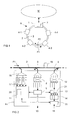
- the station 4-i comprises, first of all, a coupled reception module 8 to the first optical fiber 2 by a passive optical coupler 5, of the 2x1 type.
- the reception module 8 is more precisely constituted of a demultiplexer feeding a switch, which itself feeds four dedicated receivers each at one of four wavelengths. These four receivers are coupled to a circuit 9 for processing extracted packets supplying, on the one hand, an output 10, for example coupled to a terminal, and secondly, a module 11 control station 4-i, which will be discussed later.
- the station 4-i also comprises a transmission module 12 coupled to the first optical fiber 2 by a passive optical coupler 6, 1x2 type.
- the transmission module 12 is more precisely composed of four sources of optical signals, such as for example based on lasers, delivering carrier waves of four different wavelengths ⁇ 1 to ⁇ 4 and modulated in order to form the optical signal packets to be transmitted in the first fiber 2, a switch powered by the sources, and a multiplexer powered by the switch and supplying the passive coupler 6.
- the sources of the transmission module 12 are supplied with signals by an electronic circuit 13 charged, on the one hand, to read the contents memories 14, preferably of the FIFO type, according to rhythms defined by commands from the control module 11, and secondly, to adapt the format of the packets read in the memories 14 before the communicate with said light sources.
- Memoirs 14 are moreover supplied in packets by a power supply module 15, itself powered by an input 16, for example coupled to the aforementioned terminal, and by the module of control 11.
- the station 4-i also comprises a detection module consisting of here, four detectors 17, each responsible for observing the traffic on one of the four wavelengths ⁇ 1 to ⁇ 4 on the first optical fiber 2 in order to delivering to the control module 11 representative detection signals of an absence (or presence) of packets in the traffic observed during a longer than a DS threshold duration.
- each detector 17 is arranged to deliver signals signaling a hole in the traffic it observe on one of the four wavelengths.
- Each detector 17 is thus coupled by a set 18, consisting of a 1x2 type coupler followed by a wavelength demultiplexer, at the first optical fiber 2, upstream of the passive couplers 5 and 6.
- each detector 17 is a photodiode.
- the station 4-i is associated with an optical delay line 19 which is inserted into the first optical fiber 2 between the two passive couplers 18 and 6 detection modules 17 and emission 12. More precisely, in the example illustrated in FIG. 2, the optical delay line 19 is coupled to the first optical fiber 2 between the two passive couplers 5 and 6 of the modules receiving 8 and transmitting 12.
- the transmission modules 12 and reception 8 are coupled to the first fiber optical 2 by a single coupler 22, 2x2 type.
- the optical delay line 19 is then coupled to the first optical fiber 2 between the two couplers liabilities 18 and 22.
- optical delay lines 19 which equip the 4-i stations of the network in ring N have a length adapted to the treatment time necessary for the control module 11 and a threshold duration DS, but independent of network throughput for reasons that will be explained below.
- a synchronization signal SS j which is transmitted in the first optical fiber 2 to said stations.
- the synchronization signals are generated by some stations called master stations. More precisely, we call station master for a common wavelength considered, the station that issues the further upstream of the access node 1, in the first fiber 2, packets according to this common wavelength. Other stations that are more close to the access node and operate according to the common wavelength are then called slave stations for this common wavelength.
- station 4-1 is the station master for the four wavelengths ⁇ 1 to ⁇ 4 that are common to four stations 4-i, since it is furthest away from the access node 1 vis-à-vis amount of traffic (arrow F1).
- Stations 4-2, 4-3 and 4-4 are here slave stations for the four common wavelengths ⁇ 1 to ⁇ 4.
- it could be otherwise, especially in a network ring with many more stations, several stations to be master for different wavelengths and therefore also slave for other wavelengths.
- a synchronization signal SS j is preferably a dedicated packet injected into the first optical fiber 2, according to a common wavelength, by the transmission module 12 of the station 4-1, master for this common wavelength. More precisely, a synchronization module 21, preferentially implanted in the electronic circuit 13, is provided and responsible for generating (dedicated) synchronization packets that it transmits to the transmission module 12, specifying the wavelength to be used. .
- This generation of synchronization packet is preferentially periodic. It may possibly be supervised by the control module 11 of the master station 4-1. The periodicity is defined with respect to an internal clock (not shown) coupled to the clock clock of the master station 4-1.
- Periodity Two types can be envisaged: a periodicity "Simple”, illustrated in Figure 4, and a “complex” periodicity, illustrated in Figure 5.
- the simple periodicity consists in defining for the common wavelength considered a transmission session between two successive synchronization packets SS j and SS j + 1 , separated by a period T.
- transmission session phase of duration T during which each station 4-i operating according to the common wavelength considered may insert into the traffic associated with this common wavelength, if it wishes and if it can, a packet awaiting transmission in his memories 14. Consequently, a transmission session of duration T is associated with a burst (or "burst") of transmission.
- the complex periodicity consists in defining for the common wavelength considered n transmission sessions between two successive synchronization packets SS j and SS j + 1 , separated by a period T ', each transmission session having a fixed duration T , and n being an integer greater than or equal to two (2).
- the period of duration T 'between successive synchronization packets is equal to 2T. In other words, two transmission sessions take place here between two successive synchronization packets.
- each control module 11 of each station 4-i is configured according to the type of periodicity chosen. More specifically, each control module 11 has a processing module 20 coupled to internal clocks (one for each common wavelength), themselves coupled to the station's clock, and memorizing either only the duration of the period T between two successive synchronization packets SS j and SS j + 1 , ie the duration of the period T 'between two successive synchronization packets SS j and SS j + 1 and the duration of the transmission session T.
- each synchronization signal SS j serves to synchronize the set of internal clocks of the processing modules 20 of the stations 4-i concerned, for a given wavelength.
- the control module 11 When one of the detectors 17 of one of the slave stations, for example the station 4-4, detects the synchronization packet SS j it immediately informs the processing module 20 of the control module 11. The control module 11 synchronizes to this synchronization packet that warns it of the beginning of the current session. Then, it waits for detection signals from the detectors 17.
- the detectors 17 As long as the detectors 17 observe packets along their length detection wave, nothing happens. On the other hand, if one of the detectors 17 detects a hole, that is to say a lack of a packet on the burst with its detection wavelength, it informs the module treatment 20.
- a hole corresponds to a duration of observation without packet greater than a chosen threshold duration DS.
- the duration threshold DS is chosen less than about 100 nanoseconds (ns), and more preferably less than about 25 ns, for example 20 ns.
- This threshold duration DS defines in fact a guard time between packets successive waves transmitted on a common wavelength by stations different.
- a detector 17 finds that no packet (not dedicated to synchronization) does not circulate in the first optical fiber 2, with its detection wavelength, for a duration greater than the threshold duration DS, it sends the processing module 20 a detection signal.
- the processing module 20 derives therefrom synchronization, the DR duration remaining before the end of the session in Classes. He knows when the current session started, thanks to the last synchronization signal received, and at which point he received the signal of detection, and know in addition the duration T of a session.
- the processing module 20 can then deduce the size packet that can be inserted into the transmission burst associated with the session in progress. It then only needs to be determined in cooperation with the electronic transmission circuit 13 if it exists at the head of the queue of memories 14 a packet whose size is smaller than this maximum size, and if this is the case, to order the electronic transmission circuit 13 to extract said packet of memories 14 and transmit it to the transmission module 12 to insert it into the first optical fiber 2, according to the wavelength object of hole detection, in the emission burst exhibiting this wavelength and delayed in the optical delay line 19.
- the packet is then inserted in the transmission burst of the current session, after the last packet transmitted by one of the previous stations, leaving a time interval IT less than the threshold duration DS.
- the transmission burst comprises, before the insertion by the station 4-4, a first packet P1 inserted, for example, by the first station 4-1 just after the synchronization packet.
- SS j and a second packet P2 inserted, for example, by the third station 4-3, just after the first packet P1. Therefore, the fourth station 4-4 can insert its packet after the second packet P2.
- the processing module 20 and the synchronization module 21 may be embodied in the form of electronic circuits, software (or computer) modules, or a combination of circuits and software.
- the invention also provides a method of transmitting packets applicable within an N-ring optical network with multiplexing wavelengths.
- This process consists first of all in transmitting to stations 4-i synchronization signals, for example in the form of dedicated packets, representative of the beginning of at least one transmission session of duration T chosen, then allow each station 4-i, during a session in progress, to insert in the optical fiber 2 a packet awaiting transmission, according to the common wavelength, on the one hand when the 4-i station detects no packet according to this common wavelength for a duration of the current session greater than a chosen DS threshold duration, and secondly when the DR duration remaining before the end of this current session is longer than the time required to insert the pending packet into the fiber 2.
- the invention is not limited to the embodiments of communication, ring network and transmission method described above, only as an example, but encompasses all variants that may be considered by those skilled in the art within the scope of the claims below.
- a ring network has been described in which the synchronization signals, relating to the traffic according to a length wave, were generated by the master station for this wavelength.
- the network includes equipment dedicated to the synchronization and placed upstream of the most upstream station in relation to the access node. In this case, no station has a module synchronization, which means that the differentiation between master station and slave station no longer exists.
- the method and the stations according to the invention may apply to any type of network where at least one optical link is coupled with transmitting stations distributed along the route, these stations being intended to insert packets among transit packets issued by stations placed upstream and in a common direction of propagation.
Landscapes
- Engineering & Computer Science (AREA)
- Computer Networks & Wireless Communication (AREA)
- Signal Processing (AREA)
- Optical Communication System (AREA)
- Small-Scale Networks (AREA)
- Light Guides In General And Applications Therefor (AREA)
- Optical Fibers, Optical Fiber Cores, And Optical Fiber Bundles (AREA)
Abstract
Description
- des moyens de contrôle agencés de manière à synchroniser une horloge interne de leur station sur chaque signal de synchronisation, et à déduire d'un signal de synchronisation une fin de session d'émission,
- lorsque la station est une station maítre pour la longueur d'onde commune, elle peut comprendre des moyens de synchronisation chargés de gérer l'émission des signaux de synchronisation, par exemple sous la forme de paquets dédiés, à destination des stations esclaves. L'émission est alors préférentiellement périodique, la période étant égale à n fois la durée d'une session d'émission, n étant un entier supérieur ou égal à un,
- des moyens de réception couplés optiquement à la fibre optique en amont ou en aval des moyens de détection et en amont ou en aval des moyens d'émission, et chargés d'extraire de cette fibre des paquets selon chaque longueur d'onde détectée,
- une ligne à retard couplée optiquement à la fibre optique entre les moyens de détection et les moyens d'émission,
- des moyens de détection comportant des photodiodes en nombre égal au nombre de longueurs d'onde à détecter.
- la figure 1 illustre de façon schématique un exemple de réalisation d'un réseau de communications en anneau raccordé à un réseau fédérateur,
- la figure 2 illustre de façon schématique un premier exemple de réalisation d'une station de communication selon l'invention,
- la figure 3 illustre de façon schématique un second exemple de réalisation d'une station de communication selon l'invention,
- la figure 4 illustre de façon schématique un premier exemple de rafale de paquets conforme au protocole de remplissage de trous selon l'invention, et
- la figure 5 illustre de façon schématique un second exemple de rafale de paquets conforme au protocole de remplissage de trous selon l'invention.
Claims (12)
- Procédé de transmission de paquets au sein d'un réseau optique (N) comportant au moins deux stations (4-i) propres à insérer temporellement dans une fibre optique (2), entre des paquets en transit émis par au moins une autre station placée en amont, des paquets de signaux optiques portés par au moins une longueur d'onde commune et selon un sens de propagation commun, caractérisé en ce qu'il consiste i) à transmettre auxdites stations (4-i) des signaux de synchronisation représentatifs d'un début d'au moins une session d'émission de durée choisie, et ii) à autoriser chaque station (4-i) pendant chaque session à insérer dans ladite fibre optique (2) un paquet en attente, selon ladite longueur d'onde, d'une part lorsque ladite station ne détecte pendant une session en cours aucun paquet en transit selon cette longueur d'onde pendant une durée supérieure à une durée seuil (DS) choisie, et d'autre part lorsque la durée (DR) restant entre la fin du dernier paquet en transit et la fin de cette session en cours est supérieure à la durée nécessaire à l'insertion dudit paquet en attente dans ladite fibre optique (2), et en ce qu'en cas d'insertion, celle-ci débute après un intervalle de temps (IT), compté à partir de la fin du dernier paquet en transit, qui est inférieur à ladite durée de seuil (DS).
- Procédé selon la revendication 1, caractérisé en ce que l'on synchronise une horloge interne de chaque station (4-i) sur chaque signal de synchronisation.
- Procédé selon l'une des revendications 1 et 2, caractérisé en ce que l'on transmet auxdites stations (4-i) un signal de synchronisation de façon périodique, ladite période (T') étant égale à n fois la durée (T) d'une session d'émission, n étant un entier supérieur ou égal à un.
- Procédé selon l'une des revendications 1 à 3, caractérisé en ce qu'une dite station (4-1) située le plus en amont par rapport audit sens de propagation commun émettant des paquets selon ladite longueur d'onde commune étant dite station maítre pour cette longueur d'onde commune, chaque autre dite station opérant selon cette longueur d'onde commune étant alors dite station esclave pour ladite longueur d'onde commune, lesdits signaux de synchronisation sont transmis auxdites stations esclaves par ladite station maítre.
- Procédé selon l'une des revendications 1 à 4, caractérisé en ce que ledit signal de synchronisation est un paquet dédié.
- Station de communication (4-i) pour un réseau optique (N), ladite station étant propre à insérer temporellement dans une fibre optique (2), entre des paquets en transit émis par au moins une autre station placée en amont, des paquets de signaux optiques portés par au moins une longueur d'onde commune et selon un sens de propagation commun, caractérisée en ce qu'elle comporte i) des moyens de détection optique (17) propres à observer dans ladite fibre optique (2) le trafic associé à ladite longueur d'onde de manière à délivrer des signaux de détection représentatifs de l'absence de paquet selon ladite longueur d'onde pendant une durée supérieure à une durée seuil (DS) choisie, et ii) des moyens de contrôle (11 ) agencés, en cas de réception d'un signal de détection, postérieurement à la réception d'un signal de synchronisation représentatif du début d'au moins une session d'émission de durée (T) choisie, pour déterminer la durée (DR) restant entre la fin du dernier paquet en transit pendant une session en cours et la fin de cette session en cours, puis autoriser l'insertion dans ladite fibre optique (2) d'un paquet en attente de transmission, lorsque ladite durée (DR) restante est supérieure à la durée nécessaire à l'insertion du paquet en attente de transmission dans la fibre optique (2), et en ce qu'elle comprend des moyens d'émission (12) couplés optiquement à ladite fibre optique (2) de manière à y insérer sur ordre desdits moyens de contrôle (11) un paquet en attente de transmission, ladite insertion débutant après un intervalle de temps (IT), compté à partir de la fin du dernier paquet en transit, qui est inférieur à ladite durée de seuil (DS).
- Station selon la revendication 6, caractérisée en ce que lesdits moyens de contrôle (11) sont agencés pour synchroniser une horloge interne de leur station sur chaque signal de synchronisation, et pour déduire d'un signal de synchronisation une fin de session d'émission.
- Station selon l'une des revendications 6 et 7, une dite station (4-1) située le plus en amont par rapport audit sens de propagation commun émettant des paquets selon ladite longueur d'onde commune étant dite station maítre pour cette longueur d'onde commune, chaque autre dite station opérant selon cette longueur d'onde commune étant alors dite station esclave pour ladite longueur d'onde commune, caractérisée en ce que lorsqu'elle est maítre ladite station comprend des moyens de synchronisation (21) agencés pour gérer l'émission lesdits signaux de synchronisation à destination desdites stations esclaves.
- Station selon la revendication 8, caractérisée en ce que lesdits moyens de synchronisation (21) sont agencés pour émettre lesdits signaux de synchronisation de façon périodique, ladite période (T') étant égale à n fois la durée d'une session d'émission (T), n étant un entier supérieur ou égal à un.
- Station selon l'une des revendications 8 et 9, caractérisée en ce que lesdits moyens de synchronisation (21) sont agencés pour émettre lesdits signaux de synchronisation sous la forme de paquets dédiés.
- Station selon l'une des revendications 6 et 10, caractérisée en ce qu'elle comprend une ligne à retard optique (19) couplée optiquement à ladite fibre optique (2) entre lesdits moyens de détection (17) et lesdits moyens d'émission (12).
- Réseau optique en anneau (N), caractérisé en ce qu'il comporte un noeud d'accès (1) et au moins deux stations (4-i) selon l'une des revendications 6 à 11 couplés à au moins une fibre optique (2).
Applications Claiming Priority (2)
| Application Number | Priority Date | Filing Date | Title |
|---|---|---|---|
| FR0308518A FR2857530B1 (fr) | 2003-07-11 | 2003-07-11 | Reseau optique en anneau a protocole de remplissage de trous independant du debit |
| FR0308518 | 2003-07-11 |
Publications (2)
| Publication Number | Publication Date |
|---|---|
| EP1496720A1 true EP1496720A1 (fr) | 2005-01-12 |
| EP1496720B1 EP1496720B1 (fr) | 2011-09-14 |
Family
ID=33443269
Family Applications (1)
| Application Number | Title | Priority Date | Filing Date |
|---|---|---|---|
| EP04291591A Active EP1496720B1 (fr) | 2003-07-11 | 2004-06-23 | Réseau optique en anneau à protocole de remplissage de trous indépendant du débit |
Country Status (4)
| Country | Link |
|---|---|
| US (1) | US7539414B2 (fr) |
| EP (1) | EP1496720B1 (fr) |
| AT (1) | ATE524930T1 (fr) |
| FR (1) | FR2857530B1 (fr) |
Cited By (1)
| Publication number | Priority date | Publication date | Assignee | Title |
|---|---|---|---|---|
| FR2875085A1 (fr) * | 2004-09-08 | 2006-03-10 | Cit Alcatel | Station pour reseau optique apte a inserer des paquets dans un train de paquets en transit |
Families Citing this family (4)
| Publication number | Priority date | Publication date | Assignee | Title |
|---|---|---|---|---|
| US8064766B2 (en) * | 2007-10-08 | 2011-11-22 | Nec Laboratories America, Inc. | Orthogonal frequency division multiple access based optical ring network |
| WO2010146665A1 (fr) * | 2009-06-16 | 2010-12-23 | 富士通オプティカルコンポーネンツ株式会社 | Dispositif de communication optique et procédé de commande économe en énergie pour un dispositif de communication optique |
| JP5844016B2 (ja) * | 2013-07-19 | 2016-01-13 | 三菱電機株式会社 | リング状同期ネットワークシステムおよびタイムスレーブ局 |
| US9300565B2 (en) * | 2014-04-17 | 2016-03-29 | Accedian Networks Inc. | System and method for out-of-line real-time in-service performance measurement |
Citations (4)
| Publication number | Priority date | Publication date | Assignee | Title |
|---|---|---|---|---|
| EP0462349A1 (fr) * | 1990-06-21 | 1991-12-27 | International Business Machines Corporation | Système de communication en anneau à large bande et méthode de commande d'accès |
| US5229993A (en) * | 1991-02-25 | 1993-07-20 | Old Dominion University | Control of access through local carrier sensing for high data rate networks and control of access of synchronous messages through circulating reservation packets |
| EP1052808A1 (fr) * | 1999-05-11 | 2000-11-15 | BRITISH TELECOMMUNICATIONS public limited company | Réseau de communication utilisant classes de priorité |
| US20020154360A1 (en) * | 2000-12-22 | 2002-10-24 | Liu Heyun H. | Discrete time sequence model for slotted and synchronous switching of optical burst signals |
Family Cites Families (4)
| Publication number | Priority date | Publication date | Assignee | Title |
|---|---|---|---|---|
| US6804255B1 (en) * | 2000-10-12 | 2004-10-12 | Alcatel | Hardware implementation of channel scheduling algorithms for optical routers with FDL buffers |
| US20020118420A1 (en) * | 2000-12-22 | 2002-08-29 | Liu Heyun H. | Method and apparatus for transmitting over a slotted OBS network in in-band mode |
| FR2838005B1 (fr) * | 2002-03-28 | 2004-12-24 | Cit Alcatel | Methode dynamique d'insertion de donnees aux noeuds d'un reseau de transmission optique |
| US20040146299A1 (en) * | 2003-01-29 | 2004-07-29 | George Clapp | Periodic optical packet switching |
-
2003
- 2003-07-11 FR FR0308518A patent/FR2857530B1/fr not_active Expired - Fee Related
-
2004
- 2004-06-23 AT AT04291591T patent/ATE524930T1/de not_active IP Right Cessation
- 2004-06-23 EP EP04291591A patent/EP1496720B1/fr active Active
- 2004-07-07 US US10/885,058 patent/US7539414B2/en active Active
Patent Citations (4)
| Publication number | Priority date | Publication date | Assignee | Title |
|---|---|---|---|---|
| EP0462349A1 (fr) * | 1990-06-21 | 1991-12-27 | International Business Machines Corporation | Système de communication en anneau à large bande et méthode de commande d'accès |
| US5229993A (en) * | 1991-02-25 | 1993-07-20 | Old Dominion University | Control of access through local carrier sensing for high data rate networks and control of access of synchronous messages through circulating reservation packets |
| EP1052808A1 (fr) * | 1999-05-11 | 2000-11-15 | BRITISH TELECOMMUNICATIONS public limited company | Réseau de communication utilisant classes de priorité |
| US20020154360A1 (en) * | 2000-12-22 | 2002-10-24 | Liu Heyun H. | Discrete time sequence model for slotted and synchronous switching of optical burst signals |
Non-Patent Citations (2)
| Title |
|---|
| KYEONG SOO KIM ET AL: "Unslotted optical CSMA/CACprotocol with fairness control in metro WDM ring networks", GLOBECOM'02. 2002 - IEEE GLOBAL TELECOMMUNICATIONS CONFERENCE. CONFERENCE PROCEEDINGS. TAIPEI, TAIWAN, NOV. 17 - 21, 2002, IEEE GLOBAL TELECOMMUNICATIONS CONFERENCE, NEW YORK, NY : IEEE, US, vol. VOL. 1 OF 3, 17 November 2002 (2002-11-17), pages 2370 - 2374, XP010636172, ISBN: 0-7803-7632-3 * |
| LE SAUZE N ET AL: "A novel, low cost optical packet metropolitan ring architecture", ECOC 2001, vol. 6, 30 September 2001 (2001-09-30), AMSTERDAM, pages 66 - 67, XP010582879 * |
Cited By (2)
| Publication number | Priority date | Publication date | Assignee | Title |
|---|---|---|---|---|
| FR2875085A1 (fr) * | 2004-09-08 | 2006-03-10 | Cit Alcatel | Station pour reseau optique apte a inserer des paquets dans un train de paquets en transit |
| US7471699B2 (en) | 2004-09-08 | 2008-12-30 | Alcatel | Station for optical network suitable for inserting packets into a stream of packets in transit |
Also Published As
| Publication number | Publication date |
|---|---|
| FR2857530A1 (fr) | 2005-01-14 |
| US7539414B2 (en) | 2009-05-26 |
| EP1496720B1 (fr) | 2011-09-14 |
| US20050008368A1 (en) | 2005-01-13 |
| FR2857530B1 (fr) | 2005-09-23 |
| ATE524930T1 (de) | 2011-09-15 |
Similar Documents
| Publication | Publication Date | Title |
|---|---|---|
| EP1788736B1 (fr) | Dispositif perfectionné de transmission de données pour des équipements de communication d'un réseau optique passif | |
| CA2181078C (fr) | Reseau de transmission optique avec multiplexage de longueurs d'onde | |
| FR2758036A1 (fr) | Commutateur a mode de transfert asynchrone de cellule de plusieurs canaux d'entree a plusieurs canaux de sortie | |
| EP0108692B1 (fr) | Procédé et installation de transmission de données numériques | |
| FR2674393A1 (fr) | Synchronisation de stations terminales dans un reseau a l'alternat et multidebit. | |
| EP1496720B1 (fr) | Réseau optique en anneau à protocole de remplissage de trous indépendant du débit | |
| EP2484122A1 (fr) | Dispositif de commutation de paquets optiques | |
| EP1592159B1 (fr) | Réseau de transmission optique en arbre | |
| EP0287415A1 (fr) | Dispositif de transmission par fibres optiques, en particulier en milieu sous-marin | |
| EP1428333B1 (fr) | Reseau en anneau realise a partir d'un bus optique double | |
| EP1030471B1 (fr) | Système de transmission optique régénéré WDM | |
| EP1494383A1 (fr) | Réseau optique en anneau à multiplexage de longueurs d'onde et à transmission de signaux protégée par commutation locale d'état consécutif à une détection locale d'interruption | |
| EP1710939A1 (fr) | Réseau de communication (D)WDM à sources de lumière protégées | |
| EP2207286B1 (fr) | Procédé et équipement de distribution d'une référence de fréquence dans un réseau hétérogène | |
| EP1635605B1 (fr) | Station pour réseau optique apte à insérer des paquets dans un train de paquets en transit | |
| FR2958490A1 (fr) | Procede pour controler l'etablissement d'une connexion dans un reseau de transport | |
| WO2015044567A1 (fr) | Procédé de transmission de données dans un réseau optique à longueurs d'ondes entrelacées dans le domaine temporel | |
| EP2549773A1 (fr) | Dispositif et procédé de fusion de composantes optiques associées à une longueur d'onde en une composante optique fusionnée | |
| CA3176135C (fr) | Procede d'etablissement de communication dans un reseau d'acces optique | |
| WO2023156579A1 (fr) | Procédés et dispositifs de traitement de données montantes pour réseaux optiques passifs en cascade | |
| EP1168695A1 (fr) | Réseau sous-marin de transmissions par fibre optique | |
| WO2023156580A1 (fr) | Procédés et dispositifs de traitement de données descendantes pour réseaux optique passifs en cascade | |
| EP1401156B1 (fr) | Procédé de contrôle d'accès dans un réseau à ressources partagées, noeud et réseau correspondants | |
| EP1331748A2 (fr) | Méthode de sécurisation d'un réseau de télécommunication optique en anneau ainsi que noeud de communication à amplification et concentrateur de trafic | |
| EP0471633A1 (fr) | Réseau de communication à anneau d'écriture et anneau de lecture et procédé d'accès et de reconfiguration d'un tel réseau |
Legal Events
| Date | Code | Title | Description |
|---|---|---|---|
| PUAI | Public reference made under article 153(3) epc to a published international application that has entered the european phase |
Free format text: ORIGINAL CODE: 0009012 |
|
| AK | Designated contracting states |
Kind code of ref document: A1 Designated state(s): AT BE BG CH CY CZ DE DK EE ES FI FR GB GR HU IE IT LI LU MC NL PL PT RO SE SI SK TR |
|
| AX | Request for extension of the european patent |
Extension state: AL HR LT LV MK |
|
| 17P | Request for examination filed |
Effective date: 20041216 |
|
| AKX | Designation fees paid |
Designated state(s): AT BE BG CH CY CZ DE DK EE ES FI FR GB GR HU IE IT LI LU MC NL PL PT RO SE SI SK TR |
|
| RAP1 | Party data changed (applicant data changed or rights of an application transferred) |
Owner name: ALCATEL LUCENT |
|
| RIN1 | Information on inventor provided before grant (corrected) |
Inventor name: DOTARO, EMMANUEL Inventor name: CIAVAGLIA, LAURENT Inventor name: POPA, DANIEL Inventor name: LE SAUZE, NICOLAS Inventor name: ZAMI, THIERRY |
|
| GRAP | Despatch of communication of intention to grant a patent |
Free format text: ORIGINAL CODE: EPIDOSNIGR1 |
|
| GRAS | Grant fee paid |
Free format text: ORIGINAL CODE: EPIDOSNIGR3 |
|
| GRAA | (expected) grant |
Free format text: ORIGINAL CODE: 0009210 |
|
| AK | Designated contracting states |
Kind code of ref document: B1 Designated state(s): AT BE BG CH CY CZ DE DK EE ES FI FR GB GR HU IE IT LI LU MC NL PL PT RO SE SI SK TR |
|
| REG | Reference to a national code |
Ref country code: GB Ref legal event code: FG4D Free format text: NOT ENGLISH |
|
| REG | Reference to a national code |
Ref country code: CH Ref legal event code: EP |
|
| REG | Reference to a national code |
Ref country code: IE Ref legal event code: FG4D Free format text: LANGUAGE OF EP DOCUMENT: FRENCH |
|
| REG | Reference to a national code |
Ref country code: DE Ref legal event code: R096 Ref document number: 602004034307 Country of ref document: DE Effective date: 20111110 |
|
| REG | Reference to a national code |
Ref country code: NL Ref legal event code: VDEP Effective date: 20110914 |
|
| PG25 | Lapsed in a contracting state [announced via postgrant information from national office to epo] |
Ref country code: FI Free format text: LAPSE BECAUSE OF FAILURE TO SUBMIT A TRANSLATION OF THE DESCRIPTION OR TO PAY THE FEE WITHIN THE PRESCRIBED TIME-LIMIT Effective date: 20110914 Ref country code: SE Free format text: LAPSE BECAUSE OF FAILURE TO SUBMIT A TRANSLATION OF THE DESCRIPTION OR TO PAY THE FEE WITHIN THE PRESCRIBED TIME-LIMIT Effective date: 20110914 |
|
| RAP2 | Party data changed (patent owner data changed or rights of a patent transferred) |
Owner name: ALCATEL LUCENT |
|
| PG25 | Lapsed in a contracting state [announced via postgrant information from national office to epo] |
Ref country code: CY Free format text: LAPSE BECAUSE OF FAILURE TO SUBMIT A TRANSLATION OF THE DESCRIPTION OR TO PAY THE FEE WITHIN THE PRESCRIBED TIME-LIMIT Effective date: 20110914 Ref country code: SI Free format text: LAPSE BECAUSE OF FAILURE TO SUBMIT A TRANSLATION OF THE DESCRIPTION OR TO PAY THE FEE WITHIN THE PRESCRIBED TIME-LIMIT Effective date: 20110914 Ref country code: AT Free format text: LAPSE BECAUSE OF FAILURE TO SUBMIT A TRANSLATION OF THE DESCRIPTION OR TO PAY THE FEE WITHIN THE PRESCRIBED TIME-LIMIT Effective date: 20110914 Ref country code: GR Free format text: LAPSE BECAUSE OF FAILURE TO SUBMIT A TRANSLATION OF THE DESCRIPTION OR TO PAY THE FEE WITHIN THE PRESCRIBED TIME-LIMIT Effective date: 20111215 |
|
| REG | Reference to a national code |
Ref country code: CH Ref legal event code: PCOW Free format text: ALCATEL LUCENT;3, AVENUE OCTAVE GREARD;75007 PARIS (FR) |
|
| REG | Reference to a national code |
Ref country code: AT Ref legal event code: MK05 Ref document number: 524930 Country of ref document: AT Kind code of ref document: T Effective date: 20110914 |
|
| REG | Reference to a national code |
Ref country code: IE Ref legal event code: FD4D |
|
| PG25 | Lapsed in a contracting state [announced via postgrant information from national office to epo] |
Ref country code: CZ Free format text: LAPSE BECAUSE OF FAILURE TO SUBMIT A TRANSLATION OF THE DESCRIPTION OR TO PAY THE FEE WITHIN THE PRESCRIBED TIME-LIMIT Effective date: 20110914 Ref country code: IE Free format text: LAPSE BECAUSE OF FAILURE TO SUBMIT A TRANSLATION OF THE DESCRIPTION OR TO PAY THE FEE WITHIN THE PRESCRIBED TIME-LIMIT Effective date: 20110914 Ref country code: SK Free format text: LAPSE BECAUSE OF FAILURE TO SUBMIT A TRANSLATION OF THE DESCRIPTION OR TO PAY THE FEE WITHIN THE PRESCRIBED TIME-LIMIT Effective date: 20110914 |
|
| PG25 | Lapsed in a contracting state [announced via postgrant information from national office to epo] |
Ref country code: NL Free format text: LAPSE BECAUSE OF FAILURE TO SUBMIT A TRANSLATION OF THE DESCRIPTION OR TO PAY THE FEE WITHIN THE PRESCRIBED TIME-LIMIT Effective date: 20110914 Ref country code: EE Free format text: LAPSE BECAUSE OF FAILURE TO SUBMIT A TRANSLATION OF THE DESCRIPTION OR TO PAY THE FEE WITHIN THE PRESCRIBED TIME-LIMIT Effective date: 20110914 Ref country code: PL Free format text: LAPSE BECAUSE OF FAILURE TO SUBMIT A TRANSLATION OF THE DESCRIPTION OR TO PAY THE FEE WITHIN THE PRESCRIBED TIME-LIMIT Effective date: 20110914 Ref country code: IT Free format text: LAPSE BECAUSE OF FAILURE TO SUBMIT A TRANSLATION OF THE DESCRIPTION OR TO PAY THE FEE WITHIN THE PRESCRIBED TIME-LIMIT Effective date: 20110914 Ref country code: RO Free format text: LAPSE BECAUSE OF FAILURE TO SUBMIT A TRANSLATION OF THE DESCRIPTION OR TO PAY THE FEE WITHIN THE PRESCRIBED TIME-LIMIT Effective date: 20110914 Ref country code: PT Free format text: LAPSE BECAUSE OF FAILURE TO SUBMIT A TRANSLATION OF THE DESCRIPTION OR TO PAY THE FEE WITHIN THE PRESCRIBED TIME-LIMIT Effective date: 20120116 |
|
| PLBE | No opposition filed within time limit |
Free format text: ORIGINAL CODE: 0009261 |
|
| STAA | Information on the status of an ep patent application or granted ep patent |
Free format text: STATUS: NO OPPOSITION FILED WITHIN TIME LIMIT |
|
| PG25 | Lapsed in a contracting state [announced via postgrant information from national office to epo] |
Ref country code: DK Free format text: LAPSE BECAUSE OF FAILURE TO SUBMIT A TRANSLATION OF THE DESCRIPTION OR TO PAY THE FEE WITHIN THE PRESCRIBED TIME-LIMIT Effective date: 20110914 |
|
| 26N | No opposition filed |
Effective date: 20120615 |
|
| REG | Reference to a national code |
Ref country code: DE Ref legal event code: R097 Ref document number: 602004034307 Country of ref document: DE Effective date: 20120615 |
|
| BERE | Be: lapsed |
Owner name: ALCATEL LUCENT Effective date: 20120630 |
|
| PG25 | Lapsed in a contracting state [announced via postgrant information from national office to epo] |
Ref country code: MC Free format text: LAPSE BECAUSE OF NON-PAYMENT OF DUE FEES Effective date: 20120630 |
|
| REG | Reference to a national code |
Ref country code: CH Ref legal event code: PL |
|
| REG | Reference to a national code |
Ref country code: CH Ref legal event code: PL |
|
| PG25 | Lapsed in a contracting state [announced via postgrant information from national office to epo] |
Ref country code: BE Free format text: LAPSE BECAUSE OF NON-PAYMENT OF DUE FEES Effective date: 20120630 Ref country code: LI Free format text: LAPSE BECAUSE OF NON-PAYMENT OF DUE FEES Effective date: 20120630 Ref country code: CH Free format text: LAPSE BECAUSE OF NON-PAYMENT OF DUE FEES Effective date: 20120630 Ref country code: ES Free format text: LAPSE BECAUSE OF FAILURE TO SUBMIT A TRANSLATION OF THE DESCRIPTION OR TO PAY THE FEE WITHIN THE PRESCRIBED TIME-LIMIT Effective date: 20111225 |
|
| PG25 | Lapsed in a contracting state [announced via postgrant information from national office to epo] |
Ref country code: BG Free format text: LAPSE BECAUSE OF FAILURE TO SUBMIT A TRANSLATION OF THE DESCRIPTION OR TO PAY THE FEE WITHIN THE PRESCRIBED TIME-LIMIT Effective date: 20111214 |
|
| REG | Reference to a national code |
Ref country code: FR Ref legal event code: GC Effective date: 20131018 |
|
| PG25 | Lapsed in a contracting state [announced via postgrant information from national office to epo] |
Ref country code: TR Free format text: LAPSE BECAUSE OF FAILURE TO SUBMIT A TRANSLATION OF THE DESCRIPTION OR TO PAY THE FEE WITHIN THE PRESCRIBED TIME-LIMIT Effective date: 20110914 |
|
| PG25 | Lapsed in a contracting state [announced via postgrant information from national office to epo] |
Ref country code: LU Free format text: LAPSE BECAUSE OF NON-PAYMENT OF DUE FEES Effective date: 20120623 |
|
| PG25 | Lapsed in a contracting state [announced via postgrant information from national office to epo] |
Ref country code: HU Free format text: LAPSE BECAUSE OF FAILURE TO SUBMIT A TRANSLATION OF THE DESCRIPTION OR TO PAY THE FEE WITHIN THE PRESCRIBED TIME-LIMIT Effective date: 20040623 |
|
| REG | Reference to a national code |
Ref country code: FR Ref legal event code: RG Effective date: 20141016 |
|
| REG | Reference to a national code |
Ref country code: FR Ref legal event code: PLFP Year of fee payment: 12 |
|
| REG | Reference to a national code |
Ref country code: FR Ref legal event code: PLFP Year of fee payment: 13 |
|
| REG | Reference to a national code |
Ref country code: FR Ref legal event code: PLFP Year of fee payment: 14 |
|
| REG | Reference to a national code |
Ref country code: FR Ref legal event code: PLFP Year of fee payment: 15 |
|
| REG | Reference to a national code |
Ref country code: DE Ref legal event code: R082 Ref document number: 602004034307 Country of ref document: DE Representative=s name: METACOM LEGAL RECHTSANWAELTE, DE Ref country code: DE Ref legal event code: R082 Ref document number: 602004034307 Country of ref document: DE Representative=s name: METACOM LEGAL, DE Ref country code: DE Ref legal event code: R081 Ref document number: 602004034307 Country of ref document: DE Owner name: WSOU INVESTMENTS, LLC, LOS ANGELES, US Free format text: FORMER OWNER: ALCATEL LUCENT, PARIS, FR Ref country code: DE Ref legal event code: R082 Ref document number: 602004034307 Country of ref document: DE Representative=s name: BARKHOFF REIMANN VOSSIUS, DE |
|
| REG | Reference to a national code |
Ref country code: DE Ref legal event code: R082 Ref document number: 602004034307 Country of ref document: DE Representative=s name: METACOM LEGAL RECHTSANWAELTE, DE Ref country code: DE Ref legal event code: R082 Ref document number: 602004034307 Country of ref document: DE Representative=s name: METACOM LEGAL, DE |
|
| P01 | Opt-out of the competence of the unified patent court (upc) registered |
Effective date: 20230606 |
|
| PGFP | Annual fee paid to national office [announced via postgrant information from national office to epo] |
Ref country code: GB Payment date: 20231127 Year of fee payment: 20 |
|
| PGFP | Annual fee paid to national office [announced via postgrant information from national office to epo] |
Ref country code: FR Payment date: 20231127 Year of fee payment: 20 Ref country code: DE Payment date: 20231129 Year of fee payment: 20 |