EP1496560B1 - Ionic conduction device - Google Patents
Ionic conduction device Download PDFInfo
- Publication number
- EP1496560B1 EP1496560B1 EP04015794.3A EP04015794A EP1496560B1 EP 1496560 B1 EP1496560 B1 EP 1496560B1 EP 04015794 A EP04015794 A EP 04015794A EP 1496560 B1 EP1496560 B1 EP 1496560B1
- Authority
- EP
- European Patent Office
- Prior art keywords
- gas
- tri
- flow path
- gas flow
- oxygen
- Prior art date
- Legal status (The legal status is an assumption and is not a legal conclusion. Google has not performed a legal analysis and makes no representation as to the accuracy of the status listed.)
- Expired - Lifetime
Links
Images

Classifications
-
- H—ELECTRICITY
- H01—ELECTRIC ELEMENTS
- H01M—PROCESSES OR MEANS, e.g. BATTERIES, FOR THE DIRECT CONVERSION OF CHEMICAL ENERGY INTO ELECTRICAL ENERGY
- H01M8/00—Fuel cells; Manufacture thereof
- H01M8/04—Auxiliary arrangements, e.g. for control of pressure or for circulation of fluids
- H01M8/04007—Auxiliary arrangements, e.g. for control of pressure or for circulation of fluids related to heat exchange
- H01M8/04067—Heat exchange or temperature measuring elements, thermal insulation, e.g. heat pipes, heat pumps, fins
- H01M8/04074—Heat exchange unit structures specially adapted for fuel cell
-
- B—PERFORMING OPERATIONS; TRANSPORTING
- B01—PHYSICAL OR CHEMICAL PROCESSES OR APPARATUS IN GENERAL
- B01D—SEPARATION
- B01D53/00—Separation of gases or vapours; Recovering vapours of volatile solvents from gases; Chemical or biological purification of waste gases, e.g. engine exhaust gases, smoke, fumes, flue gases, aerosols
- B01D53/22—Separation of gases or vapours; Recovering vapours of volatile solvents from gases; Chemical or biological purification of waste gases, e.g. engine exhaust gases, smoke, fumes, flue gases, aerosols by diffusion
- B01D53/228—Separation of gases or vapours; Recovering vapours of volatile solvents from gases; Chemical or biological purification of waste gases, e.g. engine exhaust gases, smoke, fumes, flue gases, aerosols by diffusion characterised by specific membranes
-
- C—CHEMISTRY; METALLURGY
- C01—INORGANIC CHEMISTRY
- C01B—NON-METALLIC ELEMENTS; COMPOUNDS THEREOF; METALLOIDS OR COMPOUNDS THEREOF NOT COVERED BY SUBCLASS C01C
- C01B13/00—Oxygen; Ozone; Oxides or hydroxides in general
- C01B13/02—Preparation of oxygen
- C01B13/0229—Purification or separation processes
- C01B13/0248—Physical processing only
- C01B13/0251—Physical processing only by making use of membranes
- C01B13/0255—Physical processing only by making use of membranes characterised by the type of membrane
-
- H—ELECTRICITY
- H01—ELECTRIC ELEMENTS
- H01M—PROCESSES OR MEANS, e.g. BATTERIES, FOR THE DIRECT CONVERSION OF CHEMICAL ENERGY INTO ELECTRICAL ENERGY
- H01M8/00—Fuel cells; Manufacture thereof
- H01M8/02—Details
- H01M8/0202—Collectors; Separators, e.g. bipolar separators; Interconnectors
- H01M8/0258—Collectors; Separators, e.g. bipolar separators; Interconnectors characterised by the configuration of channels, e.g. by the flow field of the reactant or coolant
-
- H—ELECTRICITY
- H01—ELECTRIC ELEMENTS
- H01M—PROCESSES OR MEANS, e.g. BATTERIES, FOR THE DIRECT CONVERSION OF CHEMICAL ENERGY INTO ELECTRICAL ENERGY
- H01M8/00—Fuel cells; Manufacture thereof
- H01M8/02—Details
- H01M8/0202—Collectors; Separators, e.g. bipolar separators; Interconnectors
- H01M8/0258—Collectors; Separators, e.g. bipolar separators; Interconnectors characterised by the configuration of channels, e.g. by the flow field of the reactant or coolant
- H01M8/0263—Collectors; Separators, e.g. bipolar separators; Interconnectors characterised by the configuration of channels, e.g. by the flow field of the reactant or coolant having meandering or serpentine paths
-
- H—ELECTRICITY
- H01—ELECTRIC ELEMENTS
- H01M—PROCESSES OR MEANS, e.g. BATTERIES, FOR THE DIRECT CONVERSION OF CHEMICAL ENERGY INTO ELECTRICAL ENERGY
- H01M8/00—Fuel cells; Manufacture thereof
- H01M8/02—Details
- H01M8/0202—Collectors; Separators, e.g. bipolar separators; Interconnectors
- H01M8/0267—Collectors; Separators, e.g. bipolar separators; Interconnectors having heating or cooling means, e.g. heaters or coolant flow channels
-
- H—ELECTRICITY
- H01—ELECTRIC ELEMENTS
- H01M—PROCESSES OR MEANS, e.g. BATTERIES, FOR THE DIRECT CONVERSION OF CHEMICAL ENERGY INTO ELECTRICAL ENERGY
- H01M8/00—Fuel cells; Manufacture thereof
- H01M8/04—Auxiliary arrangements, e.g. for control of pressure or for circulation of fluids
- H01M8/04082—Arrangements for control of reactant parameters, e.g. pressure or concentration
- H01M8/04089—Arrangements for control of reactant parameters, e.g. pressure or concentration of gaseous reactants
- H01M8/04097—Arrangements for control of reactant parameters, e.g. pressure or concentration of gaseous reactants with recycling of the reactants
-
- C—CHEMISTRY; METALLURGY
- C01—INORGANIC CHEMISTRY
- C01B—NON-METALLIC ELEMENTS; COMPOUNDS THEREOF; METALLOIDS OR COMPOUNDS THEREOF NOT COVERED BY SUBCLASS C01C
- C01B2210/00—Purification or separation of specific gases
- C01B2210/0043—Impurity removed
- C01B2210/0046—Nitrogen
-
- H—ELECTRICITY
- H01—ELECTRIC ELEMENTS
- H01M—PROCESSES OR MEANS, e.g. BATTERIES, FOR THE DIRECT CONVERSION OF CHEMICAL ENERGY INTO ELECTRICAL ENERGY
- H01M8/00—Fuel cells; Manufacture thereof
- H01M8/10—Fuel cells with solid electrolytes
- H01M8/12—Fuel cells with solid electrolytes operating at high temperature, e.g. with stabilised ZrO2 electrolyte
- H01M2008/1293—Fuel cells with solid oxide electrolytes
-
- H—ELECTRICITY
- H01—ELECTRIC ELEMENTS
- H01M—PROCESSES OR MEANS, e.g. BATTERIES, FOR THE DIRECT CONVERSION OF CHEMICAL ENERGY INTO ELECTRICAL ENERGY
- H01M8/00—Fuel cells; Manufacture thereof
- H01M8/04—Auxiliary arrangements, e.g. for control of pressure or for circulation of fluids
- H01M8/04007—Auxiliary arrangements, e.g. for control of pressure or for circulation of fluids related to heat exchange
-
- H—ELECTRICITY
- H01—ELECTRIC ELEMENTS
- H01M—PROCESSES OR MEANS, e.g. BATTERIES, FOR THE DIRECT CONVERSION OF CHEMICAL ENERGY INTO ELECTRICAL ENERGY
- H01M8/00—Fuel cells; Manufacture thereof
- H01M8/06—Combination of fuel cells with means for production of reactants or for treatment of residues
- H01M8/0662—Treatment of gaseous reactants or gaseous residues, e.g. cleaning
-
- Y—GENERAL TAGGING OF NEW TECHNOLOGICAL DEVELOPMENTS; GENERAL TAGGING OF CROSS-SECTIONAL TECHNOLOGIES SPANNING OVER SEVERAL SECTIONS OF THE IPC; TECHNICAL SUBJECTS COVERED BY FORMER USPC CROSS-REFERENCE ART COLLECTIONS [XRACs] AND DIGESTS
- Y02—TECHNOLOGIES OR APPLICATIONS FOR MITIGATION OR ADAPTATION AGAINST CLIMATE CHANGE
- Y02E—REDUCTION OF GREENHOUSE GAS [GHG] EMISSIONS, RELATED TO ENERGY GENERATION, TRANSMISSION OR DISTRIBUTION
- Y02E60/00—Enabling technologies; Technologies with a potential or indirect contribution to GHG emissions mitigation
- Y02E60/30—Hydrogen technology
- Y02E60/50—Fuel cells
Definitions
- This invention relates to an ionic conduction device of the kind having a so-called tri-layer being a membrane of a suitable electrolytic material having a pair of opposed surfaces, and a gas permeable electrode in contact with each opposed surface.
- EP-0726226 a cross flow device is described, with air being fed across the one opposed membrane surface from a first side of the device, and the oxygen depleted gas passing to an opposite second side of the device, whilst the oxygen flows crosswise across the other opposed surface of the membrane to a third side of the device intermediate the first and second sides.
- gas flow paths are provided through a stack of the tri-layers, in flow paths which include passages which extend through the tri-layers.
- Such ionic conduction devices may be used alternatively as fuel cells, with a fuel gas such as hydrogen, being combined with oxygen along one opposed surface of the membrane, and exhaust gas being collected from the other opposed surface of the membrane, the device generating electrical energy across the tri-layer.
- a fuel gas such as hydrogen
- Ionic conduction devices used as fuel cells are also disclosed in US 2003/0068542 A1 and US 2002/0146601 A1 .
- the ionic conduction device is used to separate gases from a gas mixture, e.g. oxygen from air
- gases from a gas mixture e.g. oxygen from air
- such devices tend to operate inefficiently. This is because it is difficult to maintain a thermal equilibrium in the device as at least after a warm-up period, as electrical energy supplied is converted into heat which must be removed.
- the airflow to the device is optimised to achieve a thermal equilibrium, but this results in the oxygen depleted gas still containing significant volumes of oxygen, as the airflow is too great for all the oxygen to pass through the membrane as the air flows. If the airflow is reduced, more oxygen is separated from the air, but the device may become overheated.
- the oxygen depleted air it is particularly important where it is desired for the oxygen depleted air to be used, for example as an inert gas in an aircraft for example, in the aircraft's fuel tanks to reduce any risk of fire/explosion, for the oxygen depleted gas to have as low as possible an oxygen content.
- the flow of air into the device may be slowed to achieve most efficient gas separation, whilst heating and/or cooling may be effected by the flow of heat exchanging fluid to maintain thermal equilibrium throughout the device.
- the flow paths bringing the heat exchanging fluid into heat exchange relationship with the tri-layer are separate from the first, second and third gas flow paths but where the third gas may be diluted by a fourth fluid, if desired, the flow paths for the heat exchanging fluid may be coincident with the third gas flow path.
- the device is for separating gases from a gas mixture
- the first gas being air and the second gas oxygen depleted air
- the third gas being oxygen.
- first gas, air may flow from an inlet to the device to the first gas flow path
- second gas, oxygen depleted air may flow from the second gas flow path to a first outlet of the device
- third gas, oxygen may flow from the third gas flow path to a second outlet of the device.
- first and second flow paths may be connected at the one of the opposed surfaces of the membrane.
- the heat exchanging fluid may flow though the device from a heat exchanging fluid inlet, to a heat exchanging fluid outlet.
- the inlet or inlets and outlet or outlets of the device are located at respective sides of the device, where respective plenums may be provided to deliver and collect the respective gases for flow across the opposed surfaces of the membrane, and the heat exchanging fluid for flow in passages alongside at least one of the first, second and third gases.
- the device may be of the same general form as the device described in our previous patent application EP-A-0726226 but with the heat exchanging flow path of the invention, in addition.
- the inlet or inlets and outlet or outlets of the device may be located at one or each of the ends of the device, where ports may be provided through which the gases flow and the heat exchanging fluid passes, and the flow paths for the heat exchanging fluid may be provided by a labyrinth of passages across at least one of the opposed surfaces of the membrane of the tri-layer.
- the ionic conduction device may include a plurality of tri-layers separated by respective interconnects, and the passages for the flow of heat exchanging fluid may be provided by the configurations of the interconnects which may permit the heat exchanging fluid to exchange heat to or from each of the tri-layers.
- an ionic conduction device 10 for separating gases from a gas mixture, and more particularly oxygen from air includes a tri-layer construction 11 which includes a membrane 12 of a suitable electrolytic material such as for example only, Cerium Gadolinium Oxide.
- the membrane 12 has a pair of opposed surfaces 13, 14, each of which is in contact with a respective electrode 15, 16.
- the electrodes 15, 16 are gas porous and are electrically connected in a circuit whereby an electrical potential of typically 100V, may be established across the membrane 12.
- the electrodes 15, 16 may be made of Lanthanum Strontium Cobalt Ferrite or another suitable material.
- a stack of tri-layers 11 may be provided, with the tri-layers 11 being separated by interconnects 20, 21 one at either side of each of the tri-layers 11.
- the interconnects 20, 21 serve not only to space the tri-layers 11 apart to establish gas flow paths as will be described below, but also provide electrical continuity throughout the device 10.
- the interconnects 20, 21 may be made of, for example only, Haynes alloy 230, or another suitable material.
- a first gas flow path 22 is provided across one of the opposed membrane surfaces 13 for air, from inlets at a first side 25 of the device 10 where a plenum may be provided (not shown), to which a supply of air may be provided.
- the interconnect 20 in this example is of sinusoidal configuration, and multiple passageways of the first flow path 22 are provided between the interconnect 20 and the gas porous electrode 15, As the air flows across the tri-layer 11, along the one surface 13 of the membrane 12, oxygen passes through the membrane 12 and to a third gas flow path 24 provided by passageways between the sinusoidal interconnect 21 at the other opposed surface 14 of the membrane 12, to a third 27 side of the device 10.
- the oxygen depleted air continues to flow through the passageways across the surface 13 of the membrane 12, the passageways then providing a second flow path 23 to outlets at the opposite second side 26 of the device, to the side 25 where the air entered the device 10.
- another plenum may be provided to collect the oxygen depleted gas 19 , e.g. for delivery for use or exhaustion.
- the oxygen depleted gas 19 is substantially oxygen free, and thus the oxygen depleted gas may be used as an inert atmosphere, for example in a fuel tank of an aircraft or other vehicle.
- the device 10 will attain high temperatures, at least after an initial warm up period, of typically in the order of 960°C.
- a flow of a heat exchanging fluid which may be liquid or gas, is established through the device 10, in passages 36 a 36 b provided between the interconnects 20, 21 and respective end covers 37, 39 shown in figure 1 .
- the flowing heat exchanging fluid by passing through the device 10, is in heat exchange relationship with the tri-layer 11 or layers 11.
- the heat exchanging fluid flows from inlets at the second side 26 of the device 10, to the first side 25 opposite of the device 10, where a yet further plenum (not shown) may be provided to collect the heat exchanging fluid, in passages provided between the sinusoidal first interconnect 20 and the upper (as shown) cover 37.
- a yet further plenum (not shown) may be provided to collect the heat exchanging fluid, in passages provided between the sinusoidal first interconnect 20 and the upper (as shown) cover 37.
- heat exchanging fluid may also flow from a fourth side 29 between the first 25 and second 26 sides where inlets from a plenum may be provided, to the opposite third side 27, in passages provided between the lower (as shown) second sinusoidal interconnect 21 and the lower cover 39.
- the heat exchanging fluid also flows generally parallel to the oxygen gas.
- the fluid in this example is separate from each of the first, second and third gas flows.
- the flow paths 36a 36 b for the heat exchanging fluid may be coincident with the third gas flow path 24, i.e. cool or hot heat exchanging fluid as desired, may be fed into the passages of the third gas flow path 24, as well as or instead of through the other passageways, which will have the effect of diluting the oxygen, but also of cooling/heating the device 10.
- the first gas i.e. air
- the device 10 includes a plurality of tri-layers 11 separated by interconnects 20, 21 across which an electrical potential is established, arranged in a stack 43, and the air after passing through the air inlet port 40, either passes further down the stack 43 through a passageway 42, or flows along a first gas flow path 22 across one of the opposed surfaces 13 of the membrane of the first tri-layer 11 of the stack 43.
- the uppermost interconnect 20 provides an end cover for the device 10.
- Oxygen passes through the tri-layer 11 into a third fluid flow path on the other opposed surface 14 of the tri-layer 11 and hence into a passageway 45 down through the stack 43 where other oxygen, from others of the tri-layers 11 joins the oxygen from the first tri-layer 11, and the oxygen flows to an opposite end of the stack to an outlet port 44, from where the oxygen may be removed for use.
- the air which flows in the first gas flow path 22 thus becomes depleted with oxygen, and the first flow path 22 becomes the second flow path 23 from where the oxygen depleted gas flows to an outlet port 46 at the first end 41 of the stack 43.
- the oxygen depleted air at the outlet port 46 is joined by further oxygen depleted air from lower down in the stack 43, via a passageway 47 which extends through the upper tri-layer 11, to other tri-layers beneath.
- the stack 43 may have any desired number of tri-layers 11, although in the example, only two are shown.
- a fourth flow path 36 for heat exchanging fluid is provided, which extends from an inlet port 49 in the upper end 41 of the stack 43, into passages formed in or by one of, or more than one of, the interconnects 20, 21.
- the passages of the fourth flow path 36 may form a labyrinth 52 along which the heat exchanging fluid is constrained to flow, thus removing or imparting heat to the device 10 to cool or heat the device 10 as desired.
- the inlet port 49 to the fourth flow path 36 may extend down through the stack 43 and deliver heat exchanging fluid to labyrinth passages 52 in others of the interconnects of the stack, and the heat exchanging fluid, after passing along the or each of the labyrinth passages 52, flow to an outlet port 53 which is again provided at the one end 41 of the stack 43 and may be connected to fourth flow paths of other tri-layers, lower down in the stack 43.
- the coolant may be cooled by conditioning.
- the coolant fluid is air
- this may be cooled by being expanded in an air or vapour cycle air conditioning machine, to which the coolant may be recirculated after being used to cool the device 10 as described.
- the heat exchanging fluid is a hot fluid for heating the device
- the fluid may be heated exteriorly of the device 10 in a heater and recirculated to the heater after heating the device 10.
Landscapes
- Chemical & Material Sciences (AREA)
- Sustainable Development (AREA)
- Engineering & Computer Science (AREA)
- General Chemical & Material Sciences (AREA)
- Chemical Kinetics & Catalysis (AREA)
- Life Sciences & Earth Sciences (AREA)
- Electrochemistry (AREA)
- Sustainable Energy (AREA)
- Manufacturing & Machinery (AREA)
- Organic Chemistry (AREA)
- Analytical Chemistry (AREA)
- Oil, Petroleum & Natural Gas (AREA)
- Inorganic Chemistry (AREA)
- Separation Using Semi-Permeable Membranes (AREA)
- Fuel Cell (AREA)
Description
- This invention relates to an ionic conduction device of the kind having a so-called tri-layer being a membrane of a suitable electrolytic material having a pair of opposed surfaces, and a gas permeable electrode in contact with each opposed surface.
- Examples of such devices are described in our previous patent applications
EP-A-0726226 andEP-A-0950431 . - In each example, across one of the opposed surfaces of the membrane, air is passed along a flow path, while a current is applied across the tri-layer, and oxygen passes through the membrane to a gas flow path at the other of the opposed membrane surfaces, whilst oxygen depleted air, which is rich in nitrogen, passes along the one opposed surface, and hence from the device.
- In
EP-0726226 , a cross flow device is described, with air being fed across the one opposed membrane surface from a first side of the device, and the oxygen depleted gas passing to an opposite second side of the device, whilst the oxygen flows crosswise across the other opposed surface of the membrane to a third side of the device intermediate the first and second sides. - In
EP-A-0950431 , gas flow paths are provided through a stack of the tri-layers, in flow paths which include passages which extend through the tri-layers. - Such ionic conduction devices may be used alternatively as fuel cells, with a fuel gas such as hydrogen, being combined with oxygen along one opposed surface of the membrane, and exhaust gas being collected from the other opposed surface of the membrane, the device generating electrical energy across the tri-layer.
- Ionic conduction devices used as fuel cells are also disclosed in
US 2003/0068542 A1 andUS 2002/0146601 A1 . - Particularly where the ionic conduction device is used to separate gases from a gas mixture, e.g. oxygen from air, such devices tend to operate inefficiently. This is because it is difficult to maintain a thermal equilibrium in the device as at least after a warm-up period, as electrical energy supplied is converted into heat which must be removed. Conventionally, the airflow to the device is optimised to achieve a thermal equilibrium, but this results in the oxygen depleted gas still containing significant volumes of oxygen, as the airflow is too great for all the oxygen to pass through the membrane as the air flows. If the airflow is reduced, more oxygen is separated from the air, but the device may become overheated.
- It is particularly important where it is desired for the oxygen depleted air to be used, for example as an inert gas in an aircraft for example, in the aircraft's fuel tanks to reduce any risk of fire/explosion, for the oxygen depleted gas to have as low as possible an oxygen content..
- According to the invention we provide an ionic conduction device according to claim 1.
- By virtue of the present invention, where applied to a device for separating air into oxygen and oxygen depleted gas, the flow of air into the device may be slowed to achieve most efficient gas separation, whilst heating and/or cooling may be effected by the flow of heat exchanging fluid to maintain thermal equilibrium throughout the device.
- Desirably the flow paths bringing the heat exchanging fluid into heat exchange relationship with the tri-layer are separate from the first, second and third gas flow paths but where the third gas may be diluted by a fourth fluid, if desired, the flow paths for the heat exchanging fluid may be coincident with the third gas flow path.
- Thus in one example, where the device is for separating gases from a gas mixture, the first gas being air and the second gas oxygen depleted air, and the third gas being oxygen. Thus first gas, air, may flow from an inlet to the device to the first gas flow path, whilst the second gas, oxygen depleted air, may flow from the second gas flow path to a first outlet of the device, and the third gas, oxygen, may flow from the third gas flow path to a second outlet of the device. Thus the first and second flow paths may be connected at the one of the opposed surfaces of the membrane.
- The heat exchanging fluid may flow though the device from a heat exchanging fluid inlet, to a heat exchanging fluid outlet.
- In one embodiment, the inlet or inlets and outlet or outlets of the device are located at respective sides of the device, where respective plenums may be provided to deliver and collect the respective gases for flow across the opposed surfaces of the membrane, and the heat exchanging fluid for flow in passages alongside at least one of the first, second and third gases. Thus the device may be of the same general form as the device described in our previous patent application
EP-A-0726226 but with the heat exchanging flow path of the invention, in addition. - The inlet or inlets and outlet or outlets of the device may be located at one or each of the ends of the device, where ports may be provided through which the gases flow and the heat exchanging fluid passes, and the flow paths for the heat exchanging fluid may be provided by a labyrinth of passages across at least one of the opposed surfaces of the membrane of the tri-layer.
- In each case, the ionic conduction device may include a plurality of tri-layers separated by respective interconnects, and the passages for the flow of heat exchanging fluid may be provided by the configurations of the interconnects which may permit the heat exchanging fluid to exchange heat to or from each of the tri-layers.
- Embodiments of the invention will now be described by way of example, with reference to the accompanying drawings in which:-
-
FIGURE 1 is an illustrative view through a part of a first embodiment of an ionic conduction device in accordance with the invention; -
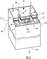
FIGURE 2 is an illustrative view, with part removed for clarity, of an ionic conduction device ; -
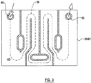
FIGURE 3 is an end cross sectional view of the device offigure 2 in the direction of the arrow X. - Referring to
figure 1 , anionic conduction device 10 for separating gases from a gas mixture, and more particularly oxygen from air, includes a tri-layerconstruction 11 which includes amembrane 12 of a suitable electrolytic material such as for example only, Cerium Gadolinium Oxide. Themembrane 12 has a pair ofopposed surfaces respective electrode electrodes membrane 12. Theelectrodes - In practice a stack of tri-layers 11 may be provided, with the tri-layers 11 being separated by
interconnects interconnects device 10. Theinterconnects - In the example of
figure 1 , a firstgas flow path 22 is provided across one of theopposed membrane surfaces 13 for air, from inlets at afirst side 25 of thedevice 10 where a plenum may be provided (not shown), to which a supply of air may be provided. Theinterconnect 20 in this example is of sinusoidal configuration, and multiple passageways of thefirst flow path 22 are provided between theinterconnect 20 and the gasporous electrode 15, As the air flows across the tri-layer 11, along the onesurface 13 of themembrane 12, oxygen passes through themembrane 12 and to a thirdgas flow path 24 provided by passageways between thesinusoidal interconnect 21 at the other opposedsurface 14 of themembrane 12, to a third 27 side of thedevice 10. - The oxygen depleted air continues to flow through the passageways across the
surface 13 of themembrane 12, the passageways then providing asecond flow path 23 to outlets at the oppositesecond side 26 of the device, to theside 25 where the air entered thedevice 10. At the oppositesecond side 26, another plenum may be provided to collect the oxygen depletedgas 19 , e.g. for delivery for use or exhaustion. Desirably, in accordance with the invention, the oxygen depletedgas 19 is substantially oxygen free, and thus the oxygen depleted gas may be used as an inert atmosphere, for example in a fuel tank of an aircraft or other vehicle. - Thus the
device 10 is a so calledcross flow device 10, in which the first and second gases (air and oxygen depleted gas) flow in one direction across the one of theopposed surfaces first side 25 to the oppositesecond side 26, whilst the third gas, (oxygen) flows across themembrane 12 transversely of the first and second gases, to thethird side 27 of thedevice 10, typically normally to the flows of the first and second gases. - In use, the
device 10 will attain high temperatures, at least after an initial warm up period, of typically in the order of 960°C. To maintain the thermal equilibrium of thedevice 10, as the electrical energy in thedevice 10 is converted to heat energy, a flow of a heat exchanging fluid, which may be liquid or gas, is established through thedevice 10, inpassages 36ainterconnects figure 1 . The flowing heat exchanging fluid, by passing through thedevice 10, is in heat exchange relationship with the tri-layer 11 orlayers 11. - The heat exchanging fluid flows from inlets at the
second side 26 of thedevice 10, to thefirst side 25 opposite of thedevice 10, where a yet further plenum (not shown) may be provided to collect the heat exchanging fluid, in passages provided between the sinusoidalfirst interconnect 20 and the upper (as shown)cover 37. Thus the heat exchanging fluid at least initially flows generally parallel to the first and second gases. If desired as shown, heat exchanging fluid may also flow from afourth side 29 between the first 25 and second 26 sides where inlets from a plenum may be provided, to the oppositethird side 27, in passages provided between the lower (as shown) secondsinusoidal interconnect 21 and thelower cover 39. Thus the heat exchanging fluid also flows generally parallel to the oxygen gas. Whether the heat exchanging fluid is arranged to flow in one direction or two directions, the fluid in this example is separate from each of the first, second and third gas flows. - In another arrangement (not shown) where it is desired to produce a product gas which is substantially oxygen depleted, i.e. pure oxygen is not required to be produced, if desired, the
flow paths 36agas flow path 24, i.e. cool or hot heat exchanging fluid as desired, may be fed into the passages of the thirdgas flow path 24, as well as or instead of through the other passageways, which will have the effect of diluting the oxygen, but also of cooling/heating thedevice 10. - Referring now to
figures 2 and3 , an ionic conduction device is shown, with similar parts to the device offigure 1 being indicated with the same reference indicae. - In the
figures 2 and3 device, the need for plenums at thesides device 10 are avoided. The first gas, i.e. air, is introduced into the device by anair inlet port 40 provided at oneend 41 of thedevice 10. Thedevice 10 includes a plurality of tri-layers 11 separated byinterconnects stack 43, and the air after passing through theair inlet port 40, either passes further down thestack 43 through apassageway 42, or flows along a firstgas flow path 22 across one of theopposed surfaces 13 of the membrane of the first tri-layer 11 of thestack 43. In this example, theuppermost interconnect 20 provides an end cover for thedevice 10. Oxygen passes through the tri-layer 11 into a third fluid flow path on the other opposedsurface 14 of the tri-layer 11 and hence into apassageway 45 down through thestack 43 where other oxygen, from others of the tri-layers 11 joins the oxygen from the first tri-layer 11, and the oxygen flows to an opposite end of the stack to anoutlet port 44, from where the oxygen may be removed for use. - The air which flows in the first
gas flow path 22 thus becomes depleted with oxygen, and thefirst flow path 22 becomes thesecond flow path 23 from where the oxygen depleted gas flows to anoutlet port 46 at thefirst end 41 of thestack 43. - The oxygen depleted air at the
outlet port 46 is joined by further oxygen depleted air from lower down in thestack 43, via apassageway 47 which extends through theupper tri-layer 11, to other tri-layers beneath. - The
stack 43 may have any desired number of tri-layers 11, although in the example, only two are shown. - A
fourth flow path 36 for heat exchanging fluid is provided, which extends from aninlet port 49 in the upper
end 41 of thestack 43, into passages formed in or by one of, or more than one of, theinterconnects figure 3 , the passages of thefourth flow path 36 may form alabyrinth 52 along which the heat exchanging fluid is constrained to flow, thus removing or imparting heat to thedevice 10 to cool or heat thedevice 10 as desired. Theinlet port 49 to thefourth flow path 36 may extend down through thestack 43 and deliver heat exchanging fluid tolabyrinth passages 52 in others of the interconnects of the stack, and the heat exchanging fluid, after passing along the or each of thelabyrinth passages 52, flow to anoutlet port 53 which is again provided at the oneend 41 of thestack 43 and may be connected to fourth flow paths of other tri-layers, lower down in thestack 43. - In each of the embodiments described, where the heat exchanging fluid is a coolant, for example to cool the
device 10, the coolant may be cooled by conditioning. Where the coolant fluid is air, this may be cooled by being expanded in an air or vapour cycle air conditioning machine, to which the coolant may be recirculated after being used to cool thedevice 10 as described. - Where the heat exchanging fluid is a hot fluid for heating the device, the fluid may be heated exteriorly of the
device 10 in a heater and recirculated to the heater after heating thedevice 10. - Various modifications may be made without departing from the scope of the invention.
- The features disclosed in the foregoing description, or the following claims, or the accompanying drawings, expressed in their specific forms or in terms of a means for performing the disclosed function, or a method or process for attaining the disclosed result, as appropriate, may, separately, or in any combination of such features, be utilised for realising the invention as defined in the appended claims.
Claims (4)
- An ionic conduction device (10) for separating gases from a gas mixture, a first gas being air, a second gas being oxygen depleted air and a third gas being oxygen, the device (10) being of the kind including a tri-layer (11) including an electrolytic membrane (12) having a pair of opposed surfaces (13, 14), and a gas permeable electrode (15, 16) in contact with each opposed surface (13, 14), the device (10) having first and second interconnects (20, 21) one located at each side of the tri-layer (11), the first interconnect (20) being of sinusoidal configuration and defining first and second gas flow paths (22, 23) for the respective first and second gases, the first and second gas flow paths (22, 23) being provided between the first interconnect (20) and the gas permeable electrode (15), the first and second gas flow paths (22, 23) extending between a first side (25) of the device (10) and a second side (26) opposite to the first side (25), the second interconnect (21) being of sinusoidal configuration and defining a third gas flow path (24) for the third gas, the third gas flow path (24) being provided between the second interconnect (21) and the gas permeable electrode (16), the third gas flow path (24) extending between a fourth side (29) of the device (10) and a third side (27) opposite to the fourth side (29), wherein the third gas flow path (24) flows transverse to the first and second gas flow paths (22, 23), the device (10) including flow paths (36a) provided between the first interconnect (20) and a first cover (37) and flow paths (36b) provided between the second interconnect (21) and a second cover (39), characterised in that the flow paths (36a, 36b) bring a heat exchanging fluid into heat exchange relationship with the tri-layer (11).
- A device according to claim 1 characterised in that the first gas flows from an inlet to the device (10) to the first gas flow path (22), whilst the second gas flows from the second gas flow path (23) to a first outlet of the device (10), and the third gas flows from the third gas flow path (24) to a second outlet of the device (10).
- A device according to claim 2 characterised in that the first (22) and second (23) flow paths are connected at the one of the opposed surfaces (13) of the membrane (12).
- A device according to any one of the preceding claims wherein a plurality of tri-layers (11) are provided, separated by respective interconnects (20, 21), and the passages (36a, 36b) for the flow of heat exchanging fluid are provided by the configurations of the interconnects (20, 21) which permit the heat exchanging fluid to exchange heat to or from each of the tri-layers (11).
Applications Claiming Priority (2)
| Application Number | Priority Date | Filing Date | Title |
|---|---|---|---|
| GB0315686 | 2003-07-04 | ||
| GBGB0315686.6A GB0315686D0 (en) | 2003-07-04 | 2003-07-04 | Ionic conduction device |
Publications (2)
| Publication Number | Publication Date |
|---|---|
| EP1496560A1 EP1496560A1 (en) | 2005-01-12 |
| EP1496560B1 true EP1496560B1 (en) | 2017-03-01 |
Family
ID=27741582
Family Applications (1)
| Application Number | Title | Priority Date | Filing Date |
|---|---|---|---|
| EP04015794.3A Expired - Lifetime EP1496560B1 (en) | 2003-07-04 | 2004-07-05 | Ionic conduction device |
Country Status (4)
| Country | Link |
|---|---|
| US (1) | US7452620B2 (en) |
| EP (1) | EP1496560B1 (en) |
| CA (1) | CA2473025A1 (en) |
| GB (1) | GB0315686D0 (en) |
Families Citing this family (5)
| Publication number | Priority date | Publication date | Assignee | Title |
|---|---|---|---|---|
| DE102005054885B4 (en) * | 2005-11-17 | 2007-12-20 | Airbus Deutschland Gmbh | Safety system to reduce the risk of explosion of a fuel tank |
| US8394552B2 (en) * | 2006-09-19 | 2013-03-12 | Hamilton Sundstrand Corporation | Jet fuel based high pressure solid oxide fuel cell system |
| DE102008013150B4 (en) * | 2008-03-07 | 2012-01-26 | Airbus Operations Gmbh | Mixing system and method for inerting a gas volume and their use |
| DE102010039276A1 (en) * | 2009-09-03 | 2011-03-10 | Theodor Gräbener GmbH & Co. KG | Process for controlling the temperature of fuel cell or electrolyzer stacks |
| KR101077199B1 (en) * | 2011-03-14 | 2011-10-27 | 김경수 | Open Cell Sodium Hypochlorite Production Equipment |
Citations (2)
| Publication number | Priority date | Publication date | Assignee | Title |
|---|---|---|---|---|
| US20020146601A1 (en) * | 2001-03-06 | 2002-10-10 | Honda Giken Kogyo Kabushiki Kaisha | Solid polymer electrolyte fuel cell assembly, fuel cell stack, and method of supplying reaction gas in fuel cell |
| US20030068542A1 (en) * | 2001-09-26 | 2003-04-10 | Dainippon Ink And Chemicals, Inc. | Bipolar plate for fuel cell, method for manufacturing the bipolar plate, and fuel cell using the bipolar plate |
Family Cites Families (5)
| Publication number | Priority date | Publication date | Assignee | Title |
|---|---|---|---|---|
| DE4016157A1 (en) | 1989-06-08 | 1990-12-13 | Asea Brown Boveri | High temp. fuel cell stack - with cells series-connected by separator plates and elastic current collectors |
| JP2966548B2 (en) | 1991-03-01 | 1999-10-25 | 大阪瓦斯株式会社 | Fuel cell |
| ES2126341T3 (en) | 1995-02-09 | 1999-03-16 | Normalair Garrett Ltd | OXYGEN GENERATING DEVICE. |
| GB9808133D0 (en) * | 1998-04-18 | 1998-06-17 | Normalair Garrett Ltd | Ionic conduction device |
| US7118820B2 (en) * | 2003-11-26 | 2006-10-10 | Utc Fuel Cells, Llc | Method and apparatus for humidification control of an energy recovery device in a fuel cell power plant |
-
2003
- 2003-07-04 GB GBGB0315686.6A patent/GB0315686D0/en not_active Ceased
-
2004
- 2004-07-02 US US10/884,458 patent/US7452620B2/en not_active Expired - Lifetime
- 2004-07-05 CA CA002473025A patent/CA2473025A1/en not_active Abandoned
- 2004-07-05 EP EP04015794.3A patent/EP1496560B1/en not_active Expired - Lifetime
Patent Citations (2)
| Publication number | Priority date | Publication date | Assignee | Title |
|---|---|---|---|---|
| US20020146601A1 (en) * | 2001-03-06 | 2002-10-10 | Honda Giken Kogyo Kabushiki Kaisha | Solid polymer electrolyte fuel cell assembly, fuel cell stack, and method of supplying reaction gas in fuel cell |
| US20030068542A1 (en) * | 2001-09-26 | 2003-04-10 | Dainippon Ink And Chemicals, Inc. | Bipolar plate for fuel cell, method for manufacturing the bipolar plate, and fuel cell using the bipolar plate |
Also Published As
| Publication number | Publication date |
|---|---|
| CA2473025A1 (en) | 2005-01-04 |
| EP1496560A1 (en) | 2005-01-12 |
| US20050008913A1 (en) | 2005-01-13 |
| US7452620B2 (en) | 2008-11-18 |
| GB0315686D0 (en) | 2003-08-13 |
Similar Documents
| Publication | Publication Date | Title |
|---|---|---|
| US5902379A (en) | Oxygen generating device | |
| JP6448770B2 (en) | Methods for high temperature electrolysis or co-electrolysis, methods for generating electricity using SOFC fuel cells, and related interconnectors, reactors, and methods of operation | |
| EP3182495B1 (en) | Solide oxide electrochemical gas separator inerting system | |
| EP0726226B1 (en) | Oxygen generating device | |
| US6106964A (en) | Solid polymer fuel cell system and method for humidifying and adjusting the temperature of a reactant stream | |
| CN105814727B (en) | Fuel cell pack and fuel cell module | |
| EP1378954A2 (en) | Co-flow anode/cathode supply heat exchanger for a solid-oxide fuel cell assembly | |
| US20020058168A1 (en) | Solid polymer fuel cell system and method for humidifying and adjusting the temperature of a reactant stream | |
| CN1312799C (en) | Fuel cell system | |
| US20180140996A1 (en) | Solid oxide electrochemical gas separator inerting system | |
| US6756144B2 (en) | Integrated recuperation loop in fuel cell stack | |
| TWI222767B (en) | Temperature/humidity regulation device for reaction gas of fuel cell set | |
| US7452620B2 (en) | Ionic conduction device | |
| TW202332105A (en) | Fuel cell interconnect optimized for operation in hydrogen fuel | |
| US8021794B2 (en) | Fuel cell with cross-shaped reformer | |
| JP4464066B2 (en) | Fuel cell system | |
| JP2002170584A (en) | Polymer electrolyte fuel cell | |
| JP2002208417A (en) | Air and fuel supply method in flat solid electrolyte fuel cell | |
| WO2011074191A1 (en) | Polyelectrolyte fuel cell, fuel cell stack provided with same, fuel cell system, and operation method for fuel cell system | |
| JP2002260708A (en) | Fuel cell laminated structure | |
| WO2004042842A2 (en) | High temperature reactant recycling for pem fuel cell humidification | |
| US6716547B2 (en) | Air condition assisted water recovery device integrated with cell stack assembly | |
| JP2003514354A (en) | Electrochemical fuel cell stack | |
| EP3513864A1 (en) | Solid oxide electrochemical gas separator inerting system | |
| JP2006196249A (en) | Fuel cell system |
Legal Events
| Date | Code | Title | Description |
|---|---|---|---|
| PUAI | Public reference made under article 153(3) epc to a published international application that has entered the european phase |
Free format text: ORIGINAL CODE: 0009012 |
|
| AK | Designated contracting states |
Kind code of ref document: A1 Designated state(s): AT BE BG CH CY CZ DE DK EE ES FI FR GB GR HU IE IT LI LU MC NL PL PT RO SE SI SK TR |
|
| AX | Request for extension of the european patent |
Extension state: AL HR LT LV MK |
|
| 17P | Request for examination filed |
Effective date: 20050630 |
|
| AKX | Designation fees paid |
Designated state(s): AT BE BG CH CY CZ DE DK EE ES FI FR GB GR HU IE IT LI LU MC NL PL PT RO SE SI SK TR |
|
| RAP1 | Party data changed (applicant data changed or rights of an application transferred) |
Owner name: HONEYWELL UK LIMITED Owner name: HONEYWELL AEROSPACE BV |
|
| 17Q | First examination report despatched |
Effective date: 20100805 |
|
| REG | Reference to a national code |
Ref country code: DE Ref legal event code: R079 Ref document number: 602004050815 Country of ref document: DE Free format text: PREVIOUS MAIN CLASS: H01M0008020000 Ipc: C01B0013020000 |
|
| GRAP | Despatch of communication of intention to grant a patent |
Free format text: ORIGINAL CODE: EPIDOSNIGR1 |
|
| RIC1 | Information provided on ipc code assigned before grant |
Ipc: H01M 8/124 20160101ALI20160909BHEP Ipc: H01M 8/0662 20160101ALI20160909BHEP Ipc: B01D 53/22 20060101ALI20160909BHEP Ipc: H01M 8/04089 20160101ALI20160909BHEP Ipc: H01M 8/0258 20160101ALI20160909BHEP Ipc: H01M 8/04007 20160101ALI20160909BHEP Ipc: C01B 13/02 20060101AFI20160909BHEP |
|
| INTG | Intention to grant announced |
Effective date: 20161013 |
|
| GRAS | Grant fee paid |
Free format text: ORIGINAL CODE: EPIDOSNIGR3 |
|
| GRAA | (expected) grant |
Free format text: ORIGINAL CODE: 0009210 |
|
| AK | Designated contracting states |
Kind code of ref document: B1 Designated state(s): AT BE BG CH CY CZ DE DK EE ES FI FR GB GR HU IE IT LI LU MC NL PL PT RO SE SI SK TR |
|
| REG | Reference to a national code |
Ref country code: GB Ref legal event code: FG4D |
|
| REG | Reference to a national code |
Ref country code: CH Ref legal event code: EP Ref country code: AT Ref legal event code: REF Ref document number: 871047 Country of ref document: AT Kind code of ref document: T Effective date: 20170315 |
|
| REG | Reference to a national code |
Ref country code: IE Ref legal event code: FG4D |
|
| REG | Reference to a national code |
Ref country code: DE Ref legal event code: R096 Ref document number: 602004050815 Country of ref document: DE |
|
| REG | Reference to a national code |
Ref country code: NL Ref legal event code: MP Effective date: 20170301 |
|
| REG | Reference to a national code |
Ref country code: AT Ref legal event code: MK05 Ref document number: 871047 Country of ref document: AT Kind code of ref document: T Effective date: 20170301 |
|
| REG | Reference to a national code |
Ref country code: FR Ref legal event code: PLFP Year of fee payment: 14 |
|
| PG25 | Lapsed in a contracting state [announced via postgrant information from national office to epo] |
Ref country code: FI Free format text: LAPSE BECAUSE OF FAILURE TO SUBMIT A TRANSLATION OF THE DESCRIPTION OR TO PAY THE FEE WITHIN THE PRESCRIBED TIME-LIMIT Effective date: 20170301 Ref country code: GR Free format text: LAPSE BECAUSE OF FAILURE TO SUBMIT A TRANSLATION OF THE DESCRIPTION OR TO PAY THE FEE WITHIN THE PRESCRIBED TIME-LIMIT Effective date: 20170602 |
|
| PG25 | Lapsed in a contracting state [announced via postgrant information from national office to epo] |
Ref country code: BG Free format text: LAPSE BECAUSE OF FAILURE TO SUBMIT A TRANSLATION OF THE DESCRIPTION OR TO PAY THE FEE WITHIN THE PRESCRIBED TIME-LIMIT Effective date: 20170601 Ref country code: AT Free format text: LAPSE BECAUSE OF FAILURE TO SUBMIT A TRANSLATION OF THE DESCRIPTION OR TO PAY THE FEE WITHIN THE PRESCRIBED TIME-LIMIT Effective date: 20170301 Ref country code: SE Free format text: LAPSE BECAUSE OF FAILURE TO SUBMIT A TRANSLATION OF THE DESCRIPTION OR TO PAY THE FEE WITHIN THE PRESCRIBED TIME-LIMIT Effective date: 20170301 Ref country code: ES Free format text: LAPSE BECAUSE OF FAILURE TO SUBMIT A TRANSLATION OF THE DESCRIPTION OR TO PAY THE FEE WITHIN THE PRESCRIBED TIME-LIMIT Effective date: 20170301 |
|
| PG25 | Lapsed in a contracting state [announced via postgrant information from national office to epo] |
Ref country code: NL Free format text: LAPSE BECAUSE OF FAILURE TO SUBMIT A TRANSLATION OF THE DESCRIPTION OR TO PAY THE FEE WITHIN THE PRESCRIBED TIME-LIMIT Effective date: 20170301 |
|
| PG25 | Lapsed in a contracting state [announced via postgrant information from national office to epo] |
Ref country code: CZ Free format text: LAPSE BECAUSE OF FAILURE TO SUBMIT A TRANSLATION OF THE DESCRIPTION OR TO PAY THE FEE WITHIN THE PRESCRIBED TIME-LIMIT Effective date: 20170301 Ref country code: EE Free format text: LAPSE BECAUSE OF FAILURE TO SUBMIT A TRANSLATION OF THE DESCRIPTION OR TO PAY THE FEE WITHIN THE PRESCRIBED TIME-LIMIT Effective date: 20170301 Ref country code: IT Free format text: LAPSE BECAUSE OF FAILURE TO SUBMIT A TRANSLATION OF THE DESCRIPTION OR TO PAY THE FEE WITHIN THE PRESCRIBED TIME-LIMIT Effective date: 20170301 Ref country code: SK Free format text: LAPSE BECAUSE OF FAILURE TO SUBMIT A TRANSLATION OF THE DESCRIPTION OR TO PAY THE FEE WITHIN THE PRESCRIBED TIME-LIMIT Effective date: 20170301 Ref country code: RO Free format text: LAPSE BECAUSE OF FAILURE TO SUBMIT A TRANSLATION OF THE DESCRIPTION OR TO PAY THE FEE WITHIN THE PRESCRIBED TIME-LIMIT Effective date: 20170301 |
|
| PG25 | Lapsed in a contracting state [announced via postgrant information from national office to epo] |
Ref country code: PT Free format text: LAPSE BECAUSE OF FAILURE TO SUBMIT A TRANSLATION OF THE DESCRIPTION OR TO PAY THE FEE WITHIN THE PRESCRIBED TIME-LIMIT Effective date: 20170703 Ref country code: PL Free format text: LAPSE BECAUSE OF FAILURE TO SUBMIT A TRANSLATION OF THE DESCRIPTION OR TO PAY THE FEE WITHIN THE PRESCRIBED TIME-LIMIT Effective date: 20170301 |
|
| REG | Reference to a national code |
Ref country code: DE Ref legal event code: R097 Ref document number: 602004050815 Country of ref document: DE |
|
| PLBE | No opposition filed within time limit |
Free format text: ORIGINAL CODE: 0009261 |
|
| STAA | Information on the status of an ep patent application or granted ep patent |
Free format text: STATUS: NO OPPOSITION FILED WITHIN TIME LIMIT |
|
| PG25 | Lapsed in a contracting state [announced via postgrant information from national office to epo] |
Ref country code: DK Free format text: LAPSE BECAUSE OF FAILURE TO SUBMIT A TRANSLATION OF THE DESCRIPTION OR TO PAY THE FEE WITHIN THE PRESCRIBED TIME-LIMIT Effective date: 20170301 |
|
| REG | Reference to a national code |
Ref country code: DE Ref legal event code: R119 Ref document number: 602004050815 Country of ref document: DE |
|
| 26N | No opposition filed |
Effective date: 20171204 |
|
| PG25 | Lapsed in a contracting state [announced via postgrant information from national office to epo] |
Ref country code: SI Free format text: LAPSE BECAUSE OF FAILURE TO SUBMIT A TRANSLATION OF THE DESCRIPTION OR TO PAY THE FEE WITHIN THE PRESCRIBED TIME-LIMIT Effective date: 20170301 |
|
| REG | Reference to a national code |
Ref country code: CH Ref legal event code: PL |
|
| GBPC | Gb: european patent ceased through non-payment of renewal fee |
Effective date: 20170705 |
|
| REG | Reference to a national code |
Ref country code: IE Ref legal event code: MM4A |
|
| PG25 | Lapsed in a contracting state [announced via postgrant information from national office to epo] |
Ref country code: GB Free format text: LAPSE BECAUSE OF NON-PAYMENT OF DUE FEES Effective date: 20170705 Ref country code: LI Free format text: LAPSE BECAUSE OF NON-PAYMENT OF DUE FEES Effective date: 20170731 Ref country code: CH Free format text: LAPSE BECAUSE OF NON-PAYMENT OF DUE FEES Effective date: 20170731 Ref country code: DE Free format text: LAPSE BECAUSE OF NON-PAYMENT OF DUE FEES Effective date: 20180201 Ref country code: IE Free format text: LAPSE BECAUSE OF NON-PAYMENT OF DUE FEES Effective date: 20170705 |
|
| REG | Reference to a national code |
Ref country code: BE Ref legal event code: MM Effective date: 20170731 |
|
| PG25 | Lapsed in a contracting state [announced via postgrant information from national office to epo] |
Ref country code: LU Free format text: LAPSE BECAUSE OF NON-PAYMENT OF DUE FEES Effective date: 20170705 |
|
| REG | Reference to a national code |
Ref country code: FR Ref legal event code: PLFP Year of fee payment: 15 |
|
| PG25 | Lapsed in a contracting state [announced via postgrant information from national office to epo] |
Ref country code: BE Free format text: LAPSE BECAUSE OF NON-PAYMENT OF DUE FEES Effective date: 20170731 |
|
| PG25 | Lapsed in a contracting state [announced via postgrant information from national office to epo] |
Ref country code: MC Free format text: LAPSE BECAUSE OF FAILURE TO SUBMIT A TRANSLATION OF THE DESCRIPTION OR TO PAY THE FEE WITHIN THE PRESCRIBED TIME-LIMIT Effective date: 20170301 Ref country code: HU Free format text: LAPSE BECAUSE OF FAILURE TO SUBMIT A TRANSLATION OF THE DESCRIPTION OR TO PAY THE FEE WITHIN THE PRESCRIBED TIME-LIMIT; INVALID AB INITIO Effective date: 20040705 |
|
| PG25 | Lapsed in a contracting state [announced via postgrant information from national office to epo] |
Ref country code: CY Free format text: LAPSE BECAUSE OF NON-PAYMENT OF DUE FEES Effective date: 20170301 |
|
| PG25 | Lapsed in a contracting state [announced via postgrant information from national office to epo] |
Ref country code: TR Free format text: LAPSE BECAUSE OF FAILURE TO SUBMIT A TRANSLATION OF THE DESCRIPTION OR TO PAY THE FEE WITHIN THE PRESCRIBED TIME-LIMIT Effective date: 20170301 |
|
| P01 | Opt-out of the competence of the unified patent court (upc) registered |
Effective date: 20230830 |
|
| PGFP | Annual fee paid to national office [announced via postgrant information from national office to epo] |
Ref country code: FR Payment date: 20230725 Year of fee payment: 20 |