EP1496428B1 - System and method for automatic configuration - Google Patents
System and method for automatic configuration Download PDFInfo
- Publication number
- EP1496428B1 EP1496428B1 EP04102519.8A EP04102519A EP1496428B1 EP 1496428 B1 EP1496428 B1 EP 1496428B1 EP 04102519 A EP04102519 A EP 04102519A EP 1496428 B1 EP1496428 B1 EP 1496428B1
- Authority
- EP
- European Patent Office
- Prior art keywords
- printer
- driver
- spooler
- data
- bidi
- Prior art date
- Legal status (The legal status is an assumption and is not a legal conclusion. Google has not performed a legal analysis and makes no representation as to the accuracy of the status listed.)
- Not-in-force
Links
Images


Classifications
-
- G—PHYSICS
- G06—COMPUTING; CALCULATING OR COUNTING
- G06F—ELECTRIC DIGITAL DATA PROCESSING
- G06F3/00—Input arrangements for transferring data to be processed into a form capable of being handled by the computer; Output arrangements for transferring data from processing unit to output unit, e.g. interface arrangements
- G06F3/12—Digital output to print unit, e.g. line printer, chain printer
- G06F3/1201—Dedicated interfaces to print systems
- G06F3/1278—Dedicated interfaces to print systems specifically adapted to adopt a particular infrastructure
- G06F3/1285—Remote printer device, e.g. being remote from client or server
-
- G—PHYSICS
- G06—COMPUTING; CALCULATING OR COUNTING
- G06F—ELECTRIC DIGITAL DATA PROCESSING
- G06F3/00—Input arrangements for transferring data to be processed into a form capable of being handled by the computer; Output arrangements for transferring data from processing unit to output unit, e.g. interface arrangements
- G06F3/12—Digital output to print unit, e.g. line printer, chain printer
- G06F3/1201—Dedicated interfaces to print systems
- G06F3/1202—Dedicated interfaces to print systems specifically adapted to achieve a particular effect
- G06F3/1203—Improving or facilitating administration, e.g. print management
- G06F3/1204—Improving or facilitating administration, e.g. print management resulting in reduced user or operator actions, e.g. presetting, automatic actions, using hardware token storing data
-
- G—PHYSICS
- G06—COMPUTING; CALCULATING OR COUNTING
- G06F—ELECTRIC DIGITAL DATA PROCESSING
- G06F3/00—Input arrangements for transferring data to be processed into a form capable of being handled by the computer; Output arrangements for transferring data from processing unit to output unit, e.g. interface arrangements
- G06F3/12—Digital output to print unit, e.g. line printer, chain printer
- G06F3/1201—Dedicated interfaces to print systems
- G06F3/1223—Dedicated interfaces to print systems specifically adapted to use a particular technique
- G06F3/1224—Client or server resources management
-
- G—PHYSICS
- G06—COMPUTING; CALCULATING OR COUNTING
- G06F—ELECTRIC DIGITAL DATA PROCESSING
- G06F3/00—Input arrangements for transferring data to be processed into a form capable of being handled by the computer; Output arrangements for transferring data from processing unit to output unit, e.g. interface arrangements
- G06F3/12—Digital output to print unit, e.g. line printer, chain printer
- G06F3/1201—Dedicated interfaces to print systems
- G06F3/1223—Dedicated interfaces to print systems specifically adapted to use a particular technique
- G06F3/1229—Printer resources management or printer maintenance, e.g. device status, power levels
- G06F3/1232—Transmitting printer device capabilities, e.g. upon request or periodically
-
- G—PHYSICS
- G06—COMPUTING; CALCULATING OR COUNTING
- G06F—ELECTRIC DIGITAL DATA PROCESSING
- G06F9/00—Arrangements for program control, e.g. control units
- G06F9/06—Arrangements for program control, e.g. control units using stored programs, i.e. using an internal store of processing equipment to receive or retain programs
- G06F9/44—Arrangements for executing specific programs
- G06F9/445—Program loading or initiating
- G06F9/44505—Configuring for program initiating, e.g. using registry, configuration files
Definitions
- This invention relates to the field of configuring a system upon installation of a network device and in particular to automatic configuration upon installation of a network printer.
- IP Internet Protocol
- the user or administrator after installing a device with duplexing capability, the user or administrator must manually go to the user interface (UI), and set the duplex unit to "installed" in order to perform two-sided printing. Furthermore, subsequent to installation, when the administrator or users add or remove installable options such as the envelope tray or memory, they must manually go to the UI to show the changes.
- UI user interface
- EP1178393A discloses a system and method for automatically updating the configuration of a printer object on a host according to configuration changes at a printer, the system making use of a driver, a spooler and a port monitor; wherein the port monitor requests and receives configuration updates from the printer and sets flags to account for changed configuration; and wherein when a driver requests configuration updates, the port monitor sends, through the spooler, the configuration changes according to the set flags.
- the invention includes a method according to claim 1.
- the invention includes a system according to claim 14.
- the invention includes a computer-readable medium according to claim 13.
- FIG. 1 is a block diagram illustrating an environment in which a system of the invention may be implemented.
- Multiple client computers 200 are connected with network printers 300 over a network 500.
- the client computers 200 and the network 500 may be similar to those described above with reference to FIG. 2 below.
- a print server 400 may also be connected with client computers 200 and printers 300 over the network 500.
- the printers 300 are available to serve the client computers 200 over the network 500. Additional network devices such as a network scanner may be included in addition to network printers 300.
- FIG. 2 illustrates an example of a suitable computing system environment 100 on which the invention may be implemented.
- the client computer 200 shown in FIG. 1 may be implemented in the computing system environment 100.
- the computing system environment 100 is only one example of a suitable computing environment and is not intended to suggest any limitation as to the scope of use or functionality of the invention. Neither should the computing environment 100 be interpreted as having any dependency or requirement relating to any one or combination of components illustrated in the exemplary operating environment 100.
- the invention may be described in the general context of computer-executable instructions, such as program modules, being executed by a computer.
- program modules include routines, programs, objects, components, data structures, etc. that perform particular tasks or implement particular abstract data types.
- program modules may be located in both local and remote computer storage media including memory storage devices.
- the exemplary system 100 for implementing the invention includes a general purpose-computing device in the form of a computer 110 including a processing unit 120, a system memory 130, and a system bus 121 that couples various system components including the system memory to the processing unit 120.
- Computer 110 typically includes a variety of computer readable media.
- computer readable media may comprise computer storage media and communication media.
- the system memory 130 includes computer storage media in the form of volatile and/or nonvolatile memory such as read only memory (ROM) 131 and random access memory (RAM) 132.
- ROM read only memory
- RAM random access memory
- BIOS basic input/output system
- RAM 132 typically contains data and/or program modules that are immediately accessible to and/or presently being operated on by processing unit 120.
- FIG. 1 illustrates operating system 134, application programs 135, other program modules 136, and program data 137.
- the computer 110 may also include other removable/nonremovable, volatile/nonvolatile computer storage media.
- FIG. 1 illustrates a hard disk drive 141 that reads from or writes to nonremovable, nonvolatile magnetic media, a magnetic disk drive 151 that reads from or writes to a removable, nonvolatile magnetic disk 152, and an optical disk drive 155 that reads from or writes to a removable, nonvolatile optical disk 156 such as a CD ROM or other optical media.
- removable/nonremovable, volatile/nonvolatile computer storage media that can be used in the exemplary operating environment include, but are not limited to, magnetic tape cassettes, flash memory cards, digital versatile disks, digital video tape, solid state RAM, solid state ROM, and the like.
- the hard disk drive 141 is typically connected to the system bus 121 through an nonremovable memory interface such as interface 140, and magnetic disk drive 151 and optical disk drive 155 are typically connected to the system bus 121 by a removable memory interface, such as interface 150.
- hard disk drive 141 is illustrated as storing operating system 144, application programs 145, other program modules 146, and program data 147. Note that these components can either be the same as or different from operating system 134, application programs 135, other program modules 136, and program data 137. Operating system 144, application programs 145, other program modules 146, and program data 147 are given different numbers here to illustrate that, at a minimum, they are different copies.
- a user may enter commands and information into the computer 110 through input devices such as a keyboard 162 and pointing device 161, commonly referred to as a mouse, trackball or touch pad.
- Other input devices may include a microphone, joystick, game pad, satellite dish, scanner, or the like.
- These and other input devices are often connected to the processing unit 120 through a user input interface 160 that is coupled to the system bus, but may be connected by other interface and bus structures, such as a parallel port, game port or a universal serial bus (USB).
- a monitor 191 or other type of display device is also connected to the system bus 121 via an interface, such as a video interface 190.
- computers may also include other peripheral output devices such as speakers 197 and printer 196, which may be connected through an output peripheral interface 195.
- the computer 110 in the present invention may operate in a networked environment using logical connections to one or more remote computers, such as a remote computer 180.
- the remote computer 180 may be a personal computer, and typically includes many or all of the elements described above relative to the computer 110, although only a memory storage device 181 has been illustrated in FIG. 2 .
- the logical connections depicted in FIG. 2 include a local area network (LAN) 171 and a wide area network (WAN) 173, but may also include other networks.
- LAN local area network
- WAN wide area network
- the computer 110 When used in a LAN networking environment, the computer 110 is connected to the LAN 171 through a network interface or adapter 170. When used in a WAN networking environment, the computer 110 typically includes a modem 172 or other means for establishing communications over the WAN 173, such as the Internet.
- the modem 172 which may be internal or external, may be connected to the system bus 121 via the user-input interface 160, or other appropriate mechanism.
- program modules depicted relative to the computer 110, or portions thereof may be stored in the remote memory storage device.
- FIG. 2 illustrates remote application programs 185 as residing on memory device 181. It will be appreciated that the network connections shown are exemplary and other means of establishing a communications link between the computers may be used.
- FIG. 3 is a block diagram illustrating components of the system of the invention. These components may be incorporated in the environment described above with reference to FIGS. 1 and 2 .
- the components displayed include a driver 30 communicating with a UI 20, applications 10, and printer description files 40.
- the components additionally include Independent Hardware Vendor (IHV) plug-ins 50, a print spooler 60, a port monitor 70, and the printing device 300, which may be disposed within one of the components described above with respect to FIG. 1 .
- the printer description files 40 will typically reside within the driver 30.
- the driver 30, the UI 20, and the applications 10 will typically be associated with the client computer 200 as shown in FIG. 1 .
- the driver 30 can retrieve features from the printer description file 40.
- the print spooler 60 receives communicates with both the driver 30 and the port monitor 70.
- the port monitor 70 communicates directly with the printing device 300.
- IHV plug-ins 50 are capable of operating between the driver 30 and the print spooler 60. All of the aforementioned components and the communications between the aforementioned components are further described below.
- FIG. 4 illustrates tools contained within the driver 30 in an embodiment of the invention.
- the driver 30 typically includes the printer description files 40 and a driver mapping extension file 34.
- the driver 30 provides an indication to the user, through the UI 20, of available printing capabilities.
- the driver mapping extension files 34 provide a mechanism for mapping between the driver 30 and the printer 300 and will be described in greater detail below.
- the printer description files 40 include a general program description (GPD) and/or general description language (GDL) file that provide a description of printing options available.
- GPD is a text based format for describing capabilities of device and is easy to change or update.
- GDL is an internally developed language with keywords to help describe capabilities of printer.
- the printer description files 40 includes tools for describing to the driver 30 what kind of information is required to inform the user regarding capabilities of the printing device 300.
- the printer description file 40 may include options such as duplex options, number of input bins, paper tray, color, size of memory, stapler, and other possible options. Also, printer options may change after purchase, thus making updates important. Maintaining knowledge of the correct configuration of the printer 300 is important for optimum performance and important for allowing the user to take advantage of all capabilities of the printer 300.
- a client 200 may know that a network printer 300 has a duplexer, but may not know how to print on two sides of the page. In order to print on two sides of a page, the client would ordinarily be required to traverse a plurality of levels to change the duplexer from "not installed” to "installed". In a network environment, an administrator is ordinarily charged with such a task. The features of the present system enable this procedure to occur automatically.
- the driver 30 will seek a current configuration upon installation of network devices such as the printer 300.
- the driver 30 can monitor the printer 300 continuously for configuration updates.
- the driver 30 may search for updates the first time a client uses a printer 300 and every time the printer 300 is started thereafter. Accordingly, if the printer 300 acquires additional features, the system will be automatically updated.
- the driver 30 needs the capability to automatically connect options with the questions of the client 200.
- the client 200 wants to know whether a duplexer is present.
- the driver 30 needs to interpret the response from the printer 300.
- the printer description files 40 include a syntax for describing bi-directional (bidi) information.
- the syntax includes extensions to pre-existing GDL files. The extensions allow a client 200 to define a question to ask and how to interpret the answers.
- the syntax includes at least two new constructs.
- the new constructs include (1) bidi queries and (2) bidi responses. Both are predetermined with knowledge of available features.
- the bidi query encapsulates query information and the bidi response encapsulates response information.
- the syntax contained within the printer description files 40 associates the bidi response and the bidi query with the features in the printer description files 40.
- the syntax also includes a plurality of keywords.
- a query string keyword is a keyword for the bidi query construct and specifies a bidi schema string as the query string.
- a response type keyword is a keyword for the bidi response construct and specifies a type of the response to the query.
- a response data keyword is also a keyword for the bidi response construct.
- the response data keyword specifies the features of the response.
- the response data keyword may be used to map responses that map to other features rather than the feature in which the query is initiated.
- a query in the "input tray” feature can yield responses related to the "papersize” feature.
- the response data keyword serves as an association between the "input tray” feature and the "papersize” feature.
- a bidi value keyword is a keyword for the bidi response construct associated with available options. It specifies an expected bidi response for each option.
- the bidi value keyword is a string representation of an anticipated response where the response is mapped to one of a feature's options. This bidi value keyword can be used in conjunction with the response data keyword to map responses back to pairs of features and options. Table 1 illustrates examples of the keyword types.
- one feature of the printer is an "input bin”.
- An “envelope feeder” represents an option associated with the input bin.
- Another feature is “paper size”. Options associated with “paper size” might include “letter” and "legal. Accordingly, the above-identified constructs and keywords of printer description file 40 can be used in three levels in GDL including (1) globally; (2) feature; or (3) option level.
- Table 2 provides an example of use of the constructs and keywords at a global level.
- the client computer 200 is able to determine the manufacturer of a network printing device.
- Table 3 provides an example for operation of the constructs and keywords at a feature level.
- the client computer is able to ensure that duplex unit is installed.
- Table 4 provides an example of use of the constructs and keywords at the option level.
- the client computer 200 can ensure that the requested options of an envelope feeder feature are installed.
- IHVs plug-ins 50 can include extensions of instances of the bidi query and bidi response constructs. For example, *BidiQuery: HPSuperStapling, *BidiResponse:HPSuperStapling. The above-mentioned query and response describe a feature specific to a feature provided by a given manufacturer. Furthermore, IHV plug-ins 50 can extend attributes of the bidi query and bidi response constructs. For example: *BidiQuery: SuperDuperFeature ⁇ *QueryString:" "*HPSuperQuery:”" ⁇ . In this example, the query string is related to a search for a specific set of features available on a device provided by a given manufacturer.
- FIG. 5 shows a more detailed view of the spooler 60 introduced in FIG. 3 .
- the spooler includes a set of bidi application program interfaces (APIs) 62 and notification tools 64.
- the notification tools 64 include a driver printer event mechanism 65 and a find next printer change notification 66. These components are further described below.
- each new bidi API 62 defines one API function for executing a bidi query and an extensible markup language (XML) based schema.
- Actions supported by the bidi APIs 62 include "Get”, “Enum”, and "Set”
- the "Get” action requires an argument with a schema string that addresses a property or value. If the argument addresses a property, the bidi API 62 will retrieve all values under this property.
- the "Enum” action requires an argument with a schema string that addresses a property or value. For a property, the bidi API retrieves the list of schemas under this property.
- the "Set” action requires two arguments including a schema string that addresses a value and a new data value.
- a request through a bidi API 62 may be represented shown below.
- the request contains a Bidi Action such as "Set”, “Get”, “GetAll”, and “EnumSchema” and one or more schemas or query strings.
- the request is an XML string that defines an action together with the list of bidi schemas to be processed.
- the client 200 requests available options related to the duplex unit and input bin features.
- the XML string shown in Table 6 represents a response to the request.
- the response is an XML string that contains the result of requested actions:
- the port monitor 70 as shown in FIG. 3 provides an abstraction of device-specific protocol, by mapping from the bidi schema to the printer specific protocol. To be able to respond to a bidi request, the port monitor 70 requires the capability to (1) retrieve necessary data from the printer's database, (2) Calculate and/or transform data and (3) return data thru Bidi APIs 62.
- the above-described mapping may be specific to a Standard Transmission Control Protocol/Internet Protocol (TCP/IP) Port Monitor (SPM).
- SPM uses Simple Network Management Protocol (SNMP) as the printer specific protocol to retrieve data stored in the printer's Management Information Bases (MIBs).
- SNMP Simple Network Management Protocol
- the driver 30 uses the associated extension file 34 that describes the mapping between bidi and MIB values.
- the example extension file illustrated below in Table 7 relates MIB and bidi values.
- extension file 34 can contain extensions of standard bidi schema. Data values described using the extension file 34 are driver specific. The client can ask for IHV extensions from the extension file 34 and receive notifications as they change. The following Table 8 illustrates this concept.
- the port monitor 70 includes a notification structure that creates an asynchronous notification channel using the spooler notification mechanism 64.
- the port monitor 70 provides a mechanism for sending data from the printer 300 to the driver 30.
- the port monitor 70 sends data as an XML file according to the above-described bidi schema.
- This type of notification is published as a bidi notification global unique identifier (BIDI_NOTIFICATION_GUID) so any application can register to listen for it.
- BIDI_NOTIFICATION_GUID bidi notification global unique identifier
- Each notification message can contain one or more port related sections and each port section can contain one or more schema changes.
- a port section is part of the notification message that contains bidi schema changes for a particular port.
- the port monitor 70 can create one notification message common to more than one port.
- Each port section addresses particular ports by a port name.
- the notification router uses port section information to route schema changes to an appropriate printer.
- the spooler 60 creates a special listener object on an opposite side of the BIDI_NOTIFICATION_GUID channel. This object receives the messages from the port monitor 70 and routes them in an appropriate direction according to a flag specified in each schema change. Notifications will be routed to the driver 30 using the driver printer event mechanism 65 only if the schema change has specified flag "drive printer event”. The spooler 60 will route notifications to any registered applications using the find next printer change notification mechanism 66 regardless of the flag in the schema change.
- Table 9 provides a sample notification provided by the notification tools 64.
- This notification provides the driver 30 with a printer alert message indicating that a low level of toner is present.
- the port monitor 70 estimates that the number of changes is so large such that the number separate notifications would be burdensome, it will send a common notification signal instead of schema changes.
- a common notification provides a signal indicating that a number of bidi schema values have changed.
- a sample notification message is provided below in Table 10.
- FIG. 6 is a flow chart illustrating a process for automatically updating a system configuration upon installation of a network printer or upon the addition of printer features.
- the driver 30 gets notification from the spooler/port monitor via a driver API (drvprinterevent) to perform a series of steps for auto-configuration.
- the driver 30 implements an operation to obtain a list of installable features and corresponding bi-directional requests from the printer description file 32.
- the driver 30 calls bi-directional APIs 62 from the spooler 60 to query for the current configuration of the feature.
- the port monitor 70 maps bidi schema to a printer specific protocol.
- step D the port monitor 70 generates a bidi notification for those schemas that have been changed.
- step E the port monitor 70 using the notification tools 64 routes a bidi notification to the driver 30 using the driver printer event mechanism 65.
- step F the port monitor 70 routes a bidi notification to the applications 10 using the printer change notification mechanism 66.
- step G the driver 30 maps bidi responses to a feature in the printer description file 40 using the bidi response construct. The driver 30 looks at the response data to find the feature and looks at its bidi value for the corresponding option for mapping.
- step H the driver 30 performs updates to the UI and system with the current configuration.
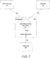
- FIG. 7 is a block diagram illustrating the interaction between the aforementioned components during a configuration update in an embodiment of the invention.
- the printer 300 communicates with the port monitor 70 using a printer specific protocol.
- the port monitor 70 creates a bidi notification channel and the spooler 60 uses the notification tools 64 to route notifications to the application 10 and the driver 30.
- the port monitor 70 obtains data from an XML file stored in a MIB database connected with the printer 300.
- the port monitor 70 converts the MIB values to expected values using the bidi schema and creates a response.
- the invention includes: (a) a syntax for representing and associating a bidi request and response with a feature via the printer description files 40 (ii) an abstraction of the device specific protocols via a set of bidi APIs 62 (iii) a schema for the bidi APIs in an extension file 34 and (iv) a notification infrastructure 64.
- the invention is described above in connection with automatic configuration of a system in order to fully use print capabilities, the features of the invention could also be used for additional purposes.
- the components described above could be used for print validation. If a conflict exists between a job ticket and the printer configuration, the auto configuration components can notify the user or perform automatic resolution to avoid putting the device in an error state.
- print validation occurs.
- the spooler 60 calls a print validation API from the set of APIs 62. If the IHV plug-ins 50 prevent use of the print validation API, the IHV 50 can perform a print validation check of the current configuration and current job settings. In either case, the spooler 60 returns a result to the driver 30 and the driver 30 ensures that the correct user interface 20 is displayed to the user.
- the user interface 20 should instruct the user on how to proceed with the job. The user can make recommended changes or ask the system to perform automatic configuration.
- the resource management solution involves a print time query to track resources available for font management or forms management. Prior to the automatic configuration solution, the driver 30 generally makes a guess as to what resources are available. When guesses are wrong, the printer 300 runs out of memory and output errors occur.
- the automatic configuration system and method described herein have many advantages.
- the invention eliminates configuration steps manually performed after device installation to obtain a correct feature set.
- the components described above allow automatic updates of configuration changes. Changes to the UI 20 are also made automatically and the system responds automatically to reflect changes. Accordingly, if an administrator adds or removes installable options, the UI becomes automatically aware of the changes.
Description
- This invention relates to the field of configuring a system upon installation of a network device and in particular to automatic configuration upon installation of a network printer.
- Today, installing a network printer is a time consuming and difficult task. Those individuals installing the network printer are generally required to perform a plurality of steps to obtain a static Internet Protocol (IP) address, create a queue, manually configure the queue, manually set a device configuration for the queue, print a test page, and send mail to users with instructions on how to connect with the newly installed network printer.
- The available processes for network printer installation are cumbersome to both small and large organizations. Within large organizations, the process of network printer installation is costly for administrators, especially when manual device configuration is required for hundreds of devices with different feature sets. Small organizations typically will not have a dedicated administrator or the expertise to perform the installation.
- As a specific example, with currently available installation techniques, after installing a device with duplexing capability, the user or administrator must manually go to the user interface (UI), and set the duplex unit to "installed" in order to perform two-sided printing. Furthermore, subsequent to installation, when the administrator or users add or remove installable options such as the envelope tray or memory, they must manually go to the UI to show the changes.
- Accordingly an improved technique is needed for network printer installation. In particular, a technique that eliminates manual configuration is desired. Automatic configuration could save the extensive effort involved in obtaining the correct feature set after installing a large number of network devices.
EP1178393A discloses a system and method for automatically updating the configuration of a printer object on a host according to configuration changes at a printer, the system making use of a driver, a spooler and a port monitor; wherein the port monitor requests and receives configuration updates from the printer and sets flags to account for changed configuration; and wherein when a driver requests configuration updates, the port monitor sends, through the spooler, the configuration changes according to the set flags. Thus, users would have access to features available on the network devices automatically without any user or administrator intervention. - In one aspect, the invention includes a method according to claim 1.
- In an additional aspect, the invention includes a system according to claim 14.
- In yet a further aspect, the invention includes a computer-readable medium according to claim 13.
- The present invention is described in detail below with reference to the attached drawing figures, wherein:
-
FIG. 1 is a block diagram showing a components of a system environment including a network printer; -
FIG. 2 is a block diagram of a suitable computing system environment for use in implementing a client computer of the present invention; -
FIG. 3 is a block diagram illustrating a system for automatic configuration in accordance with an embodiment of the invention; -
FIG. 4 is a block diagram illustrating a driver in accordance with an embodiment of the invention; -
FIG. 5 is a block diagram illustrating a spooler in accordance with an embodiment of the invention; -
FIG. 6 is a flow chart illustrating a method for automatic configuration in accordance with an embodiment of the invention; and -
FIG. 7 is a block diagram illustrating an automatic configuration process in accordance with an embodiment of the invention. -
FIG. 1 is a block diagram illustrating an environment in which a system of the invention may be implemented.Multiple client computers 200 are connected withnetwork printers 300 over anetwork 500. Theclient computers 200 and thenetwork 500 may be similar to those described above with reference toFIG. 2 below. Aprint server 400 may also be connected withclient computers 200 andprinters 300 over thenetwork 500. In the displayed environment, theprinters 300 are available to serve theclient computers 200 over thenetwork 500. Additional network devices such as a network scanner may be included in addition tonetwork printers 300. -
FIG. 2 illustrates an example of a suitablecomputing system environment 100 on which the invention may be implemented. In particular, theclient computer 200 shown inFIG. 1 may be implemented in thecomputing system environment 100. Thecomputing system environment 100 is only one example of a suitable computing environment and is not intended to suggest any limitation as to the scope of use or functionality of the invention. Neither should thecomputing environment 100 be interpreted as having any dependency or requirement relating to any one or combination of components illustrated in theexemplary operating environment 100. - The invention may be described in the general context of computer-executable instructions, such as program modules, being executed by a computer. Generally, program modules include routines, programs, objects, components, data structures, etc. that perform particular tasks or implement particular abstract data types. Moreover, those skilled in the art will appreciate that the invention may be practiced with other computer system configurations, including hand-held devices, multiprocessor systems, microprocessor-based or programmable consumer electronics, minicomputers, mainframe computers, and the like. The invention may also be practiced in distributed computing environments where tasks are performed by remote processing devices that are linked through a communications network. In a distributed computing environment, program modules may be located in both local and remote computer storage media including memory storage devices.
- With reference to
FIG. 2 , theexemplary system 100 for implementing the invention includes a general purpose-computing device in the form of acomputer 110 including aprocessing unit 120, asystem memory 130, and asystem bus 121 that couples various system components including the system memory to theprocessing unit 120. -
Computer 110 typically includes a variety of computer readable media. By way of example, and not limitation, computer readable media may comprise computer storage media and communication media. Thesystem memory 130 includes computer storage media in the form of volatile and/or nonvolatile memory such as read only memory (ROM) 131 and random access memory (RAM) 132. A basic input/output system 133 (BIOS), containing the basic routines that help to transfer information between elements withincomputer 110, such as during start-up, is typically stored inROM 131.RAM 132 typically contains data and/or program modules that are immediately accessible to and/or presently being operated on byprocessing unit 120. By way of example, and not limitation,FIG. 1 illustratesoperating system 134,application programs 135,other program modules 136, andprogram data 137. - The
computer 110 may also include other removable/nonremovable, volatile/nonvolatile computer storage media. By way of example only,FIG. 1 illustrates ahard disk drive 141 that reads from or writes to nonremovable, nonvolatile magnetic media, amagnetic disk drive 151 that reads from or writes to a removable, nonvolatilemagnetic disk 152, and anoptical disk drive 155 that reads from or writes to a removable, nonvolatileoptical disk 156 such as a CD ROM or other optical media. Other removable/nonremovable, volatile/nonvolatile computer storage media that can be used in the exemplary operating environment include, but are not limited to, magnetic tape cassettes, flash memory cards, digital versatile disks, digital video tape, solid state RAM, solid state ROM, and the like. Thehard disk drive 141 is typically connected to thesystem bus 121 through an nonremovable memory interface such asinterface 140, andmagnetic disk drive 151 andoptical disk drive 155 are typically connected to thesystem bus 121 by a removable memory interface, such asinterface 150. - The drives and their associated computer storage media discussed above and illustrated in
FIG. 2 , provide storage of computer readable instructions, data structures, program modules and other data for thecomputer 110. InFIG. 2 , for example,hard disk drive 141 is illustrated as storingoperating system 144,application programs 145,other program modules 146, andprogram data 147. Note that these components can either be the same as or different fromoperating system 134,application programs 135,other program modules 136, andprogram data 137.Operating system 144,application programs 145,other program modules 146, andprogram data 147 are given different numbers here to illustrate that, at a minimum, they are different copies. A user may enter commands and information into thecomputer 110 through input devices such as akeyboard 162 and pointingdevice 161, commonly referred to as a mouse, trackball or touch pad. Other input devices (not shown) may include a microphone, joystick, game pad, satellite dish, scanner, or the like. These and other input devices are often connected to theprocessing unit 120 through auser input interface 160 that is coupled to the system bus, but may be connected by other interface and bus structures, such as a parallel port, game port or a universal serial bus (USB). Amonitor 191 or other type of display device is also connected to thesystem bus 121 via an interface, such as avideo interface 190. In addition to the monitor, computers may also include other peripheral output devices such asspeakers 197 andprinter 196, which may be connected through an outputperipheral interface 195. - The
computer 110 in the present invention may operate in a networked environment using logical connections to one or more remote computers, such as aremote computer 180. Theremote computer 180 may be a personal computer, and typically includes many or all of the elements described above relative to thecomputer 110, although only amemory storage device 181 has been illustrated inFIG. 2 . The logical connections depicted inFIG. 2 include a local area network (LAN) 171 and a wide area network (WAN) 173, but may also include other networks. - When used in a LAN networking environment, the
computer 110 is connected to theLAN 171 through a network interface oradapter 170. When used in a WAN networking environment, thecomputer 110 typically includes amodem 172 or other means for establishing communications over theWAN 173, such as the Internet. Themodem 172, which may be internal or external, may be connected to thesystem bus 121 via the user-input interface 160, or other appropriate mechanism. In a networked environment, program modules depicted relative to thecomputer 110, or portions thereof, may be stored in the remote memory storage device. By way of example, and not limitation,FIG. 2 illustrates remote application programs 185 as residing onmemory device 181. It will be appreciated that the network connections shown are exemplary and other means of establishing a communications link between the computers may be used. - Although many other internal components of the
computer 110 are not shown, those of ordinary skill in the art will appreciate that such components and the interconnection are well known. Accordingly, additional details concerning the internal construction of thecomputer 110 need not be disclosed in connection with the present invention. -
FIG. 3 is a block diagram illustrating components of the system of the invention. These components may be incorporated in the environment described above with reference toFIGS. 1 and2 . The components displayed include adriver 30 communicating with aUI 20,applications 10, and printer description files 40. The components additionally include Independent Hardware Vendor (IHV) plug-ins 50, aprint spooler 60, aport monitor 70, and theprinting device 300, which may be disposed within one of the components described above with respect toFIG. 1 . The printer description files 40 will typically reside within thedriver 30. Thedriver 30, theUI 20, and theapplications 10 will typically be associated with theclient computer 200 as shown inFIG. 1 . Upon receiving a print request, thedriver 30 can retrieve features from theprinter description file 40. Theprint spooler 60 receives communicates with both thedriver 30 and theport monitor 70. The port monitor 70 communicates directly with theprinting device 300. IHV plug-ins 50 are capable of operating between thedriver 30 and theprint spooler 60. All of the aforementioned components and the communications between the aforementioned components are further described below. -
FIG. 4 illustrates tools contained within thedriver 30 in an embodiment of the invention. Thedriver 30 typically includes the printer description files 40 and a drivermapping extension file 34. Thedriver 30 provides an indication to the user, through theUI 20, of available printing capabilities. The driver mapping extension files 34 provide a mechanism for mapping between thedriver 30 and theprinter 300 and will be described in greater detail below. The printer description files 40 include a general program description (GPD) and/or general description language (GDL) file that provide a description of printing options available. GPD is a text based format for describing capabilities of device and is easy to change or update. GDL is an internally developed language with keywords to help describe capabilities of printer. The printer description files 40 includes tools for describing to thedriver 30 what kind of information is required to inform the user regarding capabilities of theprinting device 300. Theprinter description file 40 may include options such as duplex options, number of input bins, paper tray, color, size of memory, stapler, and other possible options. Also, printer options may change after purchase, thus making updates important. Maintaining knowledge of the correct configuration of theprinter 300 is important for optimum performance and important for allowing the user to take advantage of all capabilities of theprinter 300. - As an example, a
client 200 may know that anetwork printer 300 has a duplexer, but may not know how to print on two sides of the page. In order to print on two sides of a page, the client would ordinarily be required to traverse a plurality of levels to change the duplexer from "not installed" to "installed". In a network environment, an administrator is ordinarily charged with such a task. The features of the present system enable this procedure to occur automatically. - In the disclosed embodiments, as will be further described below, the
driver 30 will seek a current configuration upon installation of network devices such as theprinter 300. Thedriver 30 can monitor theprinter 300 continuously for configuration updates. Thedriver 30 may search for updates the first time a client uses aprinter 300 and every time theprinter 300 is started thereafter. Accordingly, if theprinter 300 acquires additional features, the system will be automatically updated. - For the automatic configuration capability, the
driver 30 needs the capability to automatically connect options with the questions of theclient 200. Suppose theclient 200 wants to know whether a duplexer is present. Thedriver 30 needs to interpret the response from theprinter 300. Accordingly, the printer description files 40 include a syntax for describing bi-directional (bidi) information. The syntax includes extensions to pre-existing GDL files. The extensions allow aclient 200 to define a question to ask and how to interpret the answers. - The syntax includes at least two new constructs. The new constructs include (1) bidi queries and (2) bidi responses. Both are predetermined with knowledge of available features. The bidi query encapsulates query information and the bidi response encapsulates response information. The syntax contained within the printer description files 40 associates the bidi response and the bidi query with the features in the printer description files 40.
- The syntax also includes a plurality of keywords. A query string keyword is a keyword for the bidi query construct and specifies a bidi schema string as the query string. A response type keyword is a keyword for the bidi response construct and specifies a type of the response to the query.
- A response data keyword is also a keyword for the bidi response construct. The response data keyword specifies the features of the response. The response data keyword may be used to map responses that map to other features rather than the feature in which the query is initiated. As an example for the use of a response data keyword, a query in the "input tray" feature can yield responses related to the "papersize" feature. The response data keyword serves as an association between the "input tray" feature and the "papersize" feature.
- A bidi value keyword is a keyword for the bidi response construct associated with available options. It specifies an expected bidi response for each option. The bidi value keyword is a string representation of an anticipated response where the response is mapped to one of a feature's options. This bidi value keyword can be used in conjunction with the response data keyword to map responses back to pairs of features and options. Table 1 illustrates examples of the keyword types.
 *BidiQuery: Instance
 {
        *QueryString: " "
        *%The string is expected to be translated to Unicode
 }
 *BidiResponse: Instance
 {
        *ResponseType: BIDI_INT - Indicates bidi data is an integer
                              BIDI_BOOL - Indicates that the bidi data is either TRUE or FALSE
                              BIDI_STRING - Indicates that the bidi data is a Unicode string
        *ResponseData: ENUM_OPTION(*Feature))
        *%Feature represents the name of the feature for responses.
        }
               *BidiQuery: Manufacturer
               {
                      *QueryString: "\Device:Manufacturer"
               }
               *BidiResponse: Manufacturer
               {
                      *ResponseType: BIDI_STRING
               }
        *Feature: DuplexUnit
        {
               *BidiQuery: DuplexInstalled
               {
               *QueryString: "\Printer.DuplexUnit:CurrentValue"
               }
               *BidiResponse: DuplexInstalled
               {
                      *ResponseType:BIDI_BOOL
                      *ResponseData:ENUM OPTION(DuplexUnit)
               }
               *Option: NotInstalled
               {
                      *BidiValue: FALSE
               }
               *Option: Installed
               {
                      *BidiValue: TRUE
               }
         }
 *Feature: InputBin
 {
 *Option: EnvelopeFeeder
 {
        *BidiQuery: MediaSize
        {
               *QueryString: "\Printer.Input.Envetope:MediaSize"
        }
        *BidiResponse: MediaSize
        {
               *ResponseType: BIDI_STRING
               *ResponseData: ENUM OPTION(papersize)
        *BidiQuery: MediaType
        {
               *QueryString: "\Printer.Input.Envelope:MediaType"
        }
        *BidiResponse: MediaType
        {
               *ResponseType: BIDI_STRING
               *ResponseData: ENUM_OPTION(MediaType)
        }
        *BidiQuery: MediaLevel
        {
               *QueryString: "\Printer.Input.Envelope:Level"
        }
        *BidiResponse: MediaLevel
        {
               *ResponseType: BIDI_STRING
               *ResponseData: ENUM OPTION(MediaLevel)
        }
 }
 <?xml version-"1.0"?
 <bidi:Request xmlns:bidi="bidi_ns">
        <Get schema="\Printer.Duplex Unit:Installed'?>
        <Get schema="\Printer.InputBin.TopBin"/>
 </bidi:Request>
 <?xml version="1.0"?>
 <bidi: Response xmlns:bidi="bidi_ns">
        <Get schema="\Printer.duplexunit:Installed" status= "0">
               <Schema name="\Printer.duplexunit.installed">
                      <bidi:Bool value="false'/>
               </schema>
        </Get>
       <Get schema="\Printer.Inputbin.topbin" status="0">
               <schema name="\printer.inputbin.topbin:installed">
                      <bidi:bool value="true"/>
               </schema>
               <schema name="\printer.inputbin.topbin:level>
                      <bidi:Int vale="45"/>
               </schema>
               <schema name="\Priner.Inputbin.topbin.mediasize">
                      <bidi:string value="letter"/>
               </schema>
               <schema name="\Priner.Inputbin.topbin.mediatype">
                      <bidi:string value="stadonery"/>
               </schema>
        </Get>
        </bidi: Response>
 ?xml version=" 1.0'?>
 <tcpbidi;Root xmlns;tcpbidi="temporary Bidi namespace".
        <Schema>
               <property name='printer">
                      <property name="layout">
                              <property name="Inputbin">
                                     <inputbin name="manual bin">
                                             mibname="manualpaper"/>
                                     <inputbin name="envetopemanual"
                                             mibname="manualenvelope"/>
                                     <inputbin name="bottombin"
                                            mibname="tray1"/>
                             </property>
                      </property>
                      <property name="output">
                             <propertyname="outputbin">
                                     <outputbin name="topbin" mibname--"standard bin"/>
                             </property>
                      </property>
               </property>
       </schema>
       </tcpbidi:Root>
 <?xml version="1.0"?>
 <tcpbidi:Root xmlns:tcpbidi="temporary bidi namespace">
       <schema>
               <property name="printer">
                      <property name="system">
                             <value name="name" oid="1.3.6.1.2.1.1.5"
                             type="BIDI_TEXT"/>
                             <value name="descr" oid=" 1.3.6.1.2.1.1.1"
                             type="BIDI_TEXT"/>
                      </property>
               </schema>
               </tcpbidi:Root>
 <?xml version="1.0"?>
 <bidi: Notification xmlns:bidi="bidi_ns">
        <port name="port 1">
               <schema name="\printer.duplexunit:Installed" drvprinterevent="true">
                      <bidi: Bool value="true"/>
               </schema>
               <schema name="\printer.alerts.alert001.code">
                      <bidi:string value="low toner"/>
               </schema>
        </port>
 </bidi:Notification>
 <?xml version="1.0"?>
 <bidi:Notification xmlns:bidi="bidi_ns">
        <Port name="port_1>
               <Event/>
        </port>
       </bidi:Notification>
Claims (24)
- A method for automatically configuring a system upon installation of a network printer (300) within the system, wherein the system includes printer description files (40), a driver (30), a spooler (60) including bi-directional application program interfaces, and a port monitor (70), the method comprising the steps of:getting (A), by the driver, upon installation of the network printer, a list of installable features and corresponding requests from the printer description files;calling (B), by the driver, the bi-directional application program interfaces from the spooler to query for a current configuration of the installable features, wherein the query comprises one or more of said requests;mapping (C), by the port monitor, bi-directional schema to a printer-specific protocol;generating (D) and routing, by the port monitor, a notification through the spooler to the driver, wherein the port monitor receives the one or more requests through the bi-directional application interfaces of the spooler, retrieves necessary data from a network printer's database, transforms the data and returns the data through the bi-directional application interfaces to the driver;mapping (G), by the driver, responses to a feature from the printer description file using the received notification from the spooler; andupdating (H), by the driver, the system with the current configuration according to the received notification.
- The method of claim 1, wherein routing a notification comprises routing a drive printer event notification to the driver to inform the driver of a configuration change.
- The method of claim 1, wherein routing a notification comprises routing a find next printer change notification to an application to allow the application to monitor and receive configuration changes automatically.
- The method of claim 1, further comprising implementing a plurality of keywords including a response type keyword for designating a response type and a response data keyword for mapping between features of the network printer.
- The method of claim 1, further comprising providing automatic configuration updates at a global level, at an option level, and at a feature level.
- The method claim 1, further comprising implementing independent hardware vendor extensions for enumerating specific features provided by a manufacturer.
- The method of claim 1, further comprising implementing the bi-directional application program interfaces to provide tools for supporting a get action, a set action, and an enumerate action.
- The method of claim 1, further comprising using the port monitor for retrieving data from a network printer database and accessing extension files from the printer description files in order to transform the data.
- The method of claim 8, further comprising using the bi-directional application program interfaces for returning the data retrieved by the port monitor.
- The method of claim 1, further being for providing extensibility for a port monitor in order to enable vendors to define new mappings using existing public bi-directional schema and extensions to existing schema, the method further comprising the steps of:permitting use of an extension file capable of describing a mapping between bi-directional values and device-specific objects; andallowing implementation of the extension file to facilitate a port monitor response to a request.
- The method of claim 10, wherein the extension file is an XML extension file.
- The method of claim 11, wherein the extension file comprises independent hardware vendor extensions of standard bi-directional schema.
- A computer-readable medium having computer-executable instructions which, when executed, cause a computer to perform the method steps recited in one of claims 1 to 12.
- A system for automatically configuring a network printer (300) upon installation of the network printer, the system comprising:a driver (30) being adapted to get, upon installation of the network printer, a list of installable features and corresponding requests from printer description files (40); a spooler including bi-directional application program interfaces; the driver being further adapted to call bi-directional application program interfaces from the spooler (60) to query for a current configuration of the installable features, wherein the query comprises one or more of said requests; the system further comprising a port monitor (70) being adapted to map bi-directional schema to a printer-specific protocol;the port monitor being further adapted to generate and route a notification through the spooler to the driver, wherein the port monitor receives the one or more requests through the bi-directional application interfaces of the spooler, retrieves necessary data from a network printer's database, transforms the data and returns the data through the bi-directional application interfaces to the driver;the driver being further adapted to map responses to a feature from the printer description file using the received notification from the spooler; andthe driver being further adapted to update the system with the current configuration according to the received notification.
- The system of claim 14, wherein the spooler comprises a drive printer event mechanism for informing the driver of a configuration change.
- The system of claim 14, wherein the spooler comprises a find next printer change notification for allowing an application to monitor and receive configuration changes automatically.
- The system of claim 14, wherein a set of constructs includes a query construct and a response construct
- The system of claim 17, wherein the printer description file comprises a plurality of keywords including a response type keyword for designating a response type and a response data keyword for mapping between features of the network printer.
- The system of claim 18, wherein the constructs and the keywords form a syntax providing tools for making automatic updates at a global level, at an option level, and at a feature level.
- The system of claim 14, further comprising independent hardware vendor extensions for enumerating specific features provided by a manufacturer.
- The system of claim 14, further comprising the bi-directional application program interfaces within the spooler for allowing transmittal of a request and a response.
- The system of claim 21, wherein the bi-directional application program interfaces provide tools for supporting a get action, a set action, and an enumerate action.
- The system of claim 14, wherein the port monitor includes a mechanism for retrieving data from a network printer database and for accessing extension files within a driver to transform the retrieved data.
- The system of claim 23, wherein the bi-directional application program interfaces provide a mechanism for returning the data retrieved by the port monitor.
Applications Claiming Priority (2)
| Application Number | Priority Date | Filing Date | Title |
|---|---|---|---|
| US608410 | 2003-06-30 | ||
| US10/608,410 US7522299B2 (en) | 2003-06-30 | 2003-06-30 | System and method for automatic configuration |
Publications (3)
| Publication Number | Publication Date |
|---|---|
| EP1496428A2 EP1496428A2 (en) | 2005-01-12 |
| EP1496428A3 EP1496428A3 (en) | 2009-04-29 |
| EP1496428B1 true EP1496428B1 (en) | 2017-05-03 |
Family
ID=33452624
Family Applications (1)
| Application Number | Title | Priority Date | Filing Date |
|---|---|---|---|
| EP04102519.8A Not-in-force EP1496428B1 (en) | 2003-06-30 | 2004-06-04 | System and method for automatic configuration |
Country Status (5)
| Country | Link |
|---|---|
| US (1) | US7522299B2 (en) |
| EP (1) | EP1496428B1 (en) |
| JP (1) | JP4931335B2 (en) |
| KR (1) | KR101099165B1 (en) |
| CN (1) | CN1577242B (en) |
Families Citing this family (45)
| Publication number | Priority date | Publication date | Assignee | Title |
|---|---|---|---|---|
| KR100524066B1 (en) * | 2003-02-08 | 2005-10-26 | 삼성전자주식회사 | Method and apparatus displaying a dialogue window of a device |
| US7861162B2 (en) * | 2003-11-14 | 2010-12-28 | Samsung Electronics Co., Ltd. | Help file generating method and apparatus |
| US20050200874A1 (en) * | 2004-03-12 | 2005-09-15 | Fuji Xerox, Co., Ltd. | Driver management method, system, unit and program |
| US8032540B1 (en) * | 2004-10-29 | 2011-10-04 | Foundry Networks, Inc. | Description-based user interface engine for network management applications |
| US20060215215A1 (en) * | 2005-03-23 | 2006-09-28 | Kumaran O R S | System and method for printer-based syndication |
| JP4795151B2 (en) * | 2005-08-12 | 2011-10-19 | キヤノン株式会社 | Information processing method, information processing apparatus, program, and storage medium |
| US7603438B2 (en) * | 2005-10-13 | 2009-10-13 | Kabushiki Kaisha Toshiba | System and method for assisted entry of database schema data |
| US7587522B2 (en) * | 2005-10-20 | 2009-09-08 | Kabushiki Kaisha Toshiba | Automated system and method for setting device module loading sequence |
| US7872765B2 (en) * | 2006-02-23 | 2011-01-18 | Ricoh Company, Ltd. | Non-postscript printer description file generating tool |
| JP4810282B2 (en) * | 2006-03-31 | 2011-11-09 | キヤノン株式会社 | Module installation method, module installation device, and program |
| JP2007317157A (en) * | 2006-04-25 | 2007-12-06 | Brother Ind Ltd | Label creating system |
| US20080043272A1 (en) * | 2006-08-18 | 2008-02-21 | Intermec Ip Corp. | Method, system and article for exposing printer functionality via a logical file system |
| US8176210B2 (en) * | 2006-11-22 | 2012-05-08 | Ricoh Company, Ltd. | Unified host application and associated methodology of integrating local service of a multi-function printer |
| JP4956247B2 (en) * | 2007-03-23 | 2012-06-20 | キヤノン株式会社 | Information processing apparatus and driver control method |
| US8589866B2 (en) * | 2007-08-29 | 2013-11-19 | Ricoh Company, Ltd. | Automatically generating capability-based computer peripheral device drivers |
| WO2009030759A2 (en) * | 2007-09-05 | 2009-03-12 | Oce-Technologies B.V. | Self-installing network computer-peripheral device |
| US20090190150A1 (en) * | 2008-01-24 | 2009-07-30 | Selvaraj Senthil K | On-Demand Print Driver |
| JP5025514B2 (en) | 2008-02-04 | 2012-09-12 | キヤノン株式会社 | Information processing apparatus, information processing apparatus control method, and computer program |
| US20100097635A1 (en) * | 2008-10-17 | 2010-04-22 | Infoprint Solutions Company Llc | Printer upgrade mechanism |
| KR101459390B1 (en) * | 2008-12-22 | 2014-11-07 | 삼성전자 주식회사 | Administrator terminal connected to image forming apparatus and client, image forming system, and remote installing method for driver thereof |
| US8427675B2 (en) * | 2009-01-27 | 2013-04-23 | Ricoh Company, Ltd. | Automatically updating a printer driver with new printing device features |
| US20100225958A1 (en) * | 2009-03-06 | 2010-09-09 | Selvaraj Senthil K | Approach For Printing To Web Services-Enabled Printing Devices |
| US8773687B2 (en) * | 2009-03-06 | 2014-07-08 | Ricoh Company, Ltd. | Driverless architecture for printing systems |
| JP2010211268A (en) * | 2009-03-06 | 2010-09-24 | Ricoh Co Ltd | Communication device, control method and program of the communication device, and system |
| US8526020B2 (en) * | 2009-03-06 | 2013-09-03 | Ricoh Company, Ltd. | Paper size support for a print system |
| US8520225B2 (en) * | 2009-03-06 | 2013-08-27 | Ricoh Company, Ltd. | Print driver localization support from printing device to support multiple user profiles |
| JP5222767B2 (en) * | 2009-03-27 | 2013-06-26 | 理想科学工業株式会社 | How to install printer related files, custom installation program |
| JP5677047B2 (en) | 2010-11-22 | 2015-02-25 | キヤノン株式会社 | Printing system, information processing apparatus, printing method, and program |
| US9182930B2 (en) | 2010-12-13 | 2015-11-10 | Microsoft Technology Licensing, Llc | Printer driver and application decoupling using event centric registration model |
| US8751778B2 (en) * | 2011-01-27 | 2014-06-10 | Wyse Technology L.L.C. | Generating, validating and applying custom extensible markup language (XML) configuration on a client having a windows-based embedded image |
| JP5868024B2 (en) * | 2011-05-19 | 2016-02-24 | キヤノン株式会社 | Information processing apparatus, information processing method, and program |
| US8904048B2 (en) | 2011-09-08 | 2014-12-02 | Microsoft Corporation | Bidi extension for connected devices |
| CN102509032B (en) * | 2011-09-23 | 2014-09-10 | 国网电力科学研究院 | Implementation method of print security monitoring system based on Windows underlying driver |
| JP5942485B2 (en) * | 2012-03-05 | 2016-06-29 | 株式会社リコー | Data processing apparatus, program, and data processing system |
| JP6102323B2 (en) * | 2012-07-10 | 2017-03-29 | 株式会社リコー | Print processing system |
| US9628335B2 (en) | 2013-11-01 | 2017-04-18 | Sap Se | Building and transporting centrally modified software systems |
| US9292234B2 (en) | 2013-11-04 | 2016-03-22 | Ricoh Company, Ltd. | Print job correction mechanism |
| JP6547462B2 (en) * | 2015-07-02 | 2019-07-24 | セイコーエプソン株式会社 | Communication control device, communication control driver and communication control method |
| JP6784136B2 (en) * | 2015-11-26 | 2020-11-11 | 株式会社リコー | Programs, information processing equipment, and information processing systems |
| KR20180074151A (en) * | 2016-12-23 | 2018-07-03 | 에이치피프린팅코리아 주식회사 | Image forming apparatus and method for setting up a network in thereof |
| KR102424056B1 (en) | 2017-10-31 | 2022-07-25 | 한국전자통신연구원 | Method for modeling network system instructions with yang language and apparatus for the same |
| CN109753407A (en) * | 2018-12-10 | 2019-05-14 | 福建网能科技开发有限责任公司 | Printer modes monitoring method based on snmp protocol |
| JP7328050B2 (en) * | 2019-07-26 | 2023-08-16 | キヤノン株式会社 | Information processing device, control method, program |
| CN111857612B (en) * | 2020-06-24 | 2022-07-12 | 厦门汉印电子技术有限公司 | GDI-based drive function module configuration method, device, equipment and storage medium |
| CN114296807B (en) * | 2021-12-08 | 2024-04-16 | 重庆品胜科技有限公司 | Automatic printer installing and identifying method based on USB communication and computer medium |
Family Cites Families (11)
| Publication number | Priority date | Publication date | Assignee | Title |
|---|---|---|---|---|
| US5960167A (en) * | 1997-03-24 | 1999-09-28 | Xerox Corporation | Printer configuration system |
| KR100420604B1 (en) * | 1997-06-23 | 2004-05-03 | 삼성전자주식회사 | Method for operating printer driver |
| JPH1191209A (en) * | 1997-09-18 | 1999-04-06 | Ricoh Co Ltd | Printer |
| US6426798B1 (en) * | 1999-03-04 | 2002-07-30 | Canon Kabushiki Kaisha | Data structure for printer description file |
| JP4325019B2 (en) * | 1999-05-25 | 2009-09-02 | 富士ゼロックス株式会社 | Parameter setting system |
| JP2001117834A (en) * | 1999-10-19 | 2001-04-27 | Fuji Xerox Co Ltd | System and method for setting network communication environment, and computer-readable recording medium recorded with network communication environment setting program |
| US6814510B1 (en) * | 2000-08-02 | 2004-11-09 | Xerox Corporation | Method and apparatus for automatic update of a printer driver configuration and status |
| US20020188646A1 (en) * | 2001-06-06 | 2002-12-12 | Terrill Jody L. | Print information capture and correlation |
| JP2002366502A (en) * | 2001-06-12 | 2002-12-20 | Ricoh Co Ltd | Automatic installation method of network printer |
| US20030200291A1 (en) * | 2002-04-23 | 2003-10-23 | Canon Kabushiki Kaisha | Web based creation of printer instances on a workstation |
| US7168003B2 (en) * | 2002-08-07 | 2007-01-23 | Hewlett-Packard Development Company, L.P. | Method and apparatus for automating printer and printer driver diagnostics and repair |
-
2003
- 2003-06-30 US US10/608,410 patent/US7522299B2/en active Active
-
2004
- 2004-06-04 EP EP04102519.8A patent/EP1496428B1/en not_active Not-in-force
- 2004-06-29 JP JP2004192282A patent/JP4931335B2/en not_active Expired - Fee Related
- 2004-06-29 KR KR1020040049362A patent/KR101099165B1/en active IP Right Grant
- 2004-06-30 CN CN2004100632807A patent/CN1577242B/en not_active Expired - Fee Related
Also Published As
| Publication number | Publication date |
|---|---|
| JP2005025755A (en) | 2005-01-27 |
| CN1577242A (en) | 2005-02-09 |
| KR20050002602A (en) | 2005-01-07 |
| JP4931335B2 (en) | 2012-05-16 |
| EP1496428A2 (en) | 2005-01-12 |
| CN1577242B (en) | 2010-05-12 |
| KR101099165B1 (en) | 2011-12-27 |
| US7522299B2 (en) | 2009-04-21 |
| EP1496428A3 (en) | 2009-04-29 |
| US20040263900A1 (en) | 2004-12-30 |
Similar Documents
| Publication | Publication Date | Title |
|---|---|---|
| EP1496428B1 (en) | System and method for automatic configuration | |
| US9602678B2 (en) | Peripheral device control system and method | |
| US7316022B2 (en) | Information processing apparatus, information processing method, alternate response apparatus, response method, control program, and network system | |
| KR101176757B1 (en) | Service discovery and publication | |
| US8223363B2 (en) | Universal print driver with best fit discovery | |
| US20070136485A1 (en) | Information processing apparatus | |
| US20080180712A1 (en) | Universal print driver with full discovery | |
| US20080180726A1 (en) | Universal print driver with simple discovery | |
| JP2003108448A (en) | Device, method, and program for controlling network device | |
| US8611248B2 (en) | Information processing apparatus, device information display method, and computer-readable storage medium | |
| US20070263236A1 (en) | Automatic discovery of print media attributes | |
| JP2011034562A (en) | Print system | |
| US20100220352A1 (en) | Image forming apparatus, image forming system, and information processing method | |
| JP4467955B2 (en) | Information processing device, peripheral device control system, peripheral device control method applied to information processing device, and program thereof | |
| JP4458884B2 (en) | Device configuration information acquisition method and information processing apparatus | |
| US20040199651A1 (en) | Apparatus, method and system of providing information | |
| US8271621B2 (en) | Metadata communication system | |
| WO2021118591A1 (en) | Method and apparatus of bidirectional (bidi) communication of printer driver |
Legal Events
| Date | Code | Title | Description |
|---|---|---|---|
| PUAI | Public reference made under article 153(3) epc to a published international application that has entered the european phase |
Free format text: ORIGINAL CODE: 0009012 |
|
| AK | Designated contracting states |
Kind code of ref document: A2 Designated state(s): AT BE BG CH CY CZ DE DK EE ES FI FR GB GR HU IE IT LI LU MC NL PL PT RO SE SI SK TR |
|
| AX | Request for extension of the european patent |
Extension state: AL HR LT LV MK |
|
| RIN1 | Information on inventor provided before grant (corrected) |
Inventor name: PAVICEVIC, IVAN Inventor name: NGUYEN, AMANDA GIANG-TIEN Inventor name: FENELON, MICHAEL P. |
|
| PUAL | Search report despatched |
Free format text: ORIGINAL CODE: 0009013 |
|
| AK | Designated contracting states |
Kind code of ref document: A3 Designated state(s): AT BE BG CH CY CZ DE DK EE ES FI FR GB GR HU IE IT LI LU MC NL PL PT RO SE SI SK TR |
|
| AX | Request for extension of the european patent |
Extension state: AL HR LT LV MK |
|
| 17P | Request for examination filed |
Effective date: 20090918 |
|
| 17Q | First examination report despatched |
Effective date: 20091106 |
|
| AKX | Designation fees paid |
Designated state(s): AT BE BG CH CY CZ DE DK EE ES FI FR GB GR HU IE IT LI LU MC NL PL PT RO SE SI SK TR |
|
| RAP1 | Party data changed (applicant data changed or rights of an application transferred) |
Owner name: MICROSOFT TECHNOLOGY LICENSING, LLC |
|
| GRAP | Despatch of communication of intention to grant a patent |
Free format text: ORIGINAL CODE: EPIDOSNIGR1 |
|
| RIC1 | Information provided on ipc code assigned before grant |
Ipc: G06F 9/445 20060101ALN20161101BHEP Ipc: G06F 3/12 20060101AFI20161101BHEP |
|
| INTG | Intention to grant announced |
Effective date: 20161128 |
|
| RIN1 | Information on inventor provided before grant (corrected) |
Inventor name: FENELON, MICHAEL P. Inventor name: NGUYEN, AMANDA GIANG-TIEN Inventor name: PAVICEVIC, IVAN |
|
| GRAS | Grant fee paid |
Free format text: ORIGINAL CODE: EPIDOSNIGR3 |
|
| GRAA | (expected) grant |
Free format text: ORIGINAL CODE: 0009210 |
|
| AK | Designated contracting states |
Kind code of ref document: B1 Designated state(s): AT BE BG CH CY CZ DE DK EE ES FI FR GB GR HU IE IT LI LU MC NL PL PT RO SE SI SK TR |
|
| REG | Reference to a national code |
Ref country code: GB Ref legal event code: FG4D |
|
| REG | Reference to a national code |
Ref country code: AT Ref legal event code: REF Ref document number: 890683 Country of ref document: AT Kind code of ref document: T Effective date: 20170515 Ref country code: CH Ref legal event code: EP |
|
| REG | Reference to a national code |
Ref country code: FR Ref legal event code: PLFP Year of fee payment: 14 |
|
| REG | Reference to a national code |
Ref country code: IE Ref legal event code: FG4D |
|
| REG | Reference to a national code |
Ref country code: DE Ref legal event code: R096 Ref document number: 602004051181 Country of ref document: DE |
|
| REG | Reference to a national code |
Ref country code: NL Ref legal event code: FP |
|
| PGFP | Annual fee paid to national office [announced via postgrant information from national office to epo] |
Ref country code: FR Payment date: 20170530 Year of fee payment: 14 Ref country code: GB Payment date: 20170531 Year of fee payment: 14 |
|
| REG | Reference to a national code |
Ref country code: AT Ref legal event code: MK05 Ref document number: 890683 Country of ref document: AT Kind code of ref document: T Effective date: 20170503 |
|
| PG25 | Lapsed in a contracting state [announced via postgrant information from national office to epo] |
Ref country code: GR Free format text: LAPSE BECAUSE OF FAILURE TO SUBMIT A TRANSLATION OF THE DESCRIPTION OR TO PAY THE FEE WITHIN THE PRESCRIBED TIME-LIMIT Effective date: 20170804 Ref country code: FI Free format text: LAPSE BECAUSE OF FAILURE TO SUBMIT A TRANSLATION OF THE DESCRIPTION OR TO PAY THE FEE WITHIN THE PRESCRIBED TIME-LIMIT Effective date: 20170503 Ref country code: ES Free format text: LAPSE BECAUSE OF FAILURE TO SUBMIT A TRANSLATION OF THE DESCRIPTION OR TO PAY THE FEE WITHIN THE PRESCRIBED TIME-LIMIT Effective date: 20170503 Ref country code: AT Free format text: LAPSE BECAUSE OF FAILURE TO SUBMIT A TRANSLATION OF THE DESCRIPTION OR TO PAY THE FEE WITHIN THE PRESCRIBED TIME-LIMIT Effective date: 20170503 |
|
| PG25 | Lapsed in a contracting state [announced via postgrant information from national office to epo] |
Ref country code: PL Free format text: LAPSE BECAUSE OF FAILURE TO SUBMIT A TRANSLATION OF THE DESCRIPTION OR TO PAY THE FEE WITHIN THE PRESCRIBED TIME-LIMIT Effective date: 20170503 Ref country code: SE Free format text: LAPSE BECAUSE OF FAILURE TO SUBMIT A TRANSLATION OF THE DESCRIPTION OR TO PAY THE FEE WITHIN THE PRESCRIBED TIME-LIMIT Effective date: 20170503 Ref country code: BG Free format text: LAPSE BECAUSE OF FAILURE TO SUBMIT A TRANSLATION OF THE DESCRIPTION OR TO PAY THE FEE WITHIN THE PRESCRIBED TIME-LIMIT Effective date: 20170803 |
|
| PG25 | Lapsed in a contracting state [announced via postgrant information from national office to epo] |
Ref country code: CZ Free format text: LAPSE BECAUSE OF FAILURE TO SUBMIT A TRANSLATION OF THE DESCRIPTION OR TO PAY THE FEE WITHIN THE PRESCRIBED TIME-LIMIT Effective date: 20170503 Ref country code: RO Free format text: LAPSE BECAUSE OF FAILURE TO SUBMIT A TRANSLATION OF THE DESCRIPTION OR TO PAY THE FEE WITHIN THE PRESCRIBED TIME-LIMIT Effective date: 20170503 Ref country code: DK Free format text: LAPSE BECAUSE OF FAILURE TO SUBMIT A TRANSLATION OF THE DESCRIPTION OR TO PAY THE FEE WITHIN THE PRESCRIBED TIME-LIMIT Effective date: 20170503 Ref country code: EE Free format text: LAPSE BECAUSE OF FAILURE TO SUBMIT A TRANSLATION OF THE DESCRIPTION OR TO PAY THE FEE WITHIN THE PRESCRIBED TIME-LIMIT Effective date: 20170503 Ref country code: SK Free format text: LAPSE BECAUSE OF FAILURE TO SUBMIT A TRANSLATION OF THE DESCRIPTION OR TO PAY THE FEE WITHIN THE PRESCRIBED TIME-LIMIT Effective date: 20170503 |
|
| REG | Reference to a national code |
Ref country code: CH Ref legal event code: PL |
|
| REG | Reference to a national code |
Ref country code: DE Ref legal event code: R097 Ref document number: 602004051181 Country of ref document: DE |
|
| PG25 | Lapsed in a contracting state [announced via postgrant information from national office to epo] |
Ref country code: IT Free format text: LAPSE BECAUSE OF FAILURE TO SUBMIT A TRANSLATION OF THE DESCRIPTION OR TO PAY THE FEE WITHIN THE PRESCRIBED TIME-LIMIT Effective date: 20170503 |
|
| PLBE | No opposition filed within time limit |
Free format text: ORIGINAL CODE: 0009261 |
|
| STAA | Information on the status of an ep patent application or granted ep patent |
Free format text: STATUS: NO OPPOSITION FILED WITHIN TIME LIMIT |
|
| REG | Reference to a national code |
Ref country code: IE Ref legal event code: MM4A |
|
| 26N | No opposition filed |
Effective date: 20180206 |
|
| PG25 | Lapsed in a contracting state [announced via postgrant information from national office to epo] |
Ref country code: LI Free format text: LAPSE BECAUSE OF NON-PAYMENT OF DUE FEES Effective date: 20170630 Ref country code: LU Free format text: LAPSE BECAUSE OF NON-PAYMENT OF DUE FEES Effective date: 20170604 Ref country code: CH Free format text: LAPSE BECAUSE OF NON-PAYMENT OF DUE FEES Effective date: 20170630 Ref country code: IE Free format text: LAPSE BECAUSE OF NON-PAYMENT OF DUE FEES Effective date: 20170604 |
|
| PG25 | Lapsed in a contracting state [announced via postgrant information from national office to epo] |
Ref country code: SI Free format text: LAPSE BECAUSE OF FAILURE TO SUBMIT A TRANSLATION OF THE DESCRIPTION OR TO PAY THE FEE WITHIN THE PRESCRIBED TIME-LIMIT Effective date: 20170503 |
|
| REG | Reference to a national code |
Ref country code: BE Ref legal event code: MM Effective date: 20170630 |
|
| PG25 | Lapsed in a contracting state [announced via postgrant information from national office to epo] |
Ref country code: BE Free format text: LAPSE BECAUSE OF NON-PAYMENT OF DUE FEES Effective date: 20170630 |
|
| GBPC | Gb: european patent ceased through non-payment of renewal fee |
Effective date: 20180604 |
|
| PG25 | Lapsed in a contracting state [announced via postgrant information from national office to epo] |
Ref country code: GB Free format text: LAPSE BECAUSE OF NON-PAYMENT OF DUE FEES Effective date: 20180604 Ref country code: FR Free format text: LAPSE BECAUSE OF NON-PAYMENT OF DUE FEES Effective date: 20180630 |
|
| PG25 | Lapsed in a contracting state [announced via postgrant information from national office to epo] |
Ref country code: HU Free format text: LAPSE BECAUSE OF FAILURE TO SUBMIT A TRANSLATION OF THE DESCRIPTION OR TO PAY THE FEE WITHIN THE PRESCRIBED TIME-LIMIT; INVALID AB INITIO Effective date: 20040604 Ref country code: MC Free format text: LAPSE BECAUSE OF FAILURE TO SUBMIT A TRANSLATION OF THE DESCRIPTION OR TO PAY THE FEE WITHIN THE PRESCRIBED TIME-LIMIT Effective date: 20170503 |
|
| PGFP | Annual fee paid to national office [announced via postgrant information from national office to epo] |
Ref country code: NL Payment date: 20190515 Year of fee payment: 16 |
|
| PGFP | Annual fee paid to national office [announced via postgrant information from national office to epo] |
Ref country code: DE Payment date: 20190521 Year of fee payment: 16 |
|
| PG25 | Lapsed in a contracting state [announced via postgrant information from national office to epo] |
Ref country code: CY Free format text: LAPSE BECAUSE OF NON-PAYMENT OF DUE FEES Effective date: 20170503 |
|
| PG25 | Lapsed in a contracting state [announced via postgrant information from national office to epo] |
Ref country code: TR Free format text: LAPSE BECAUSE OF FAILURE TO SUBMIT A TRANSLATION OF THE DESCRIPTION OR TO PAY THE FEE WITHIN THE PRESCRIBED TIME-LIMIT Effective date: 20170503 |
|
| PG25 | Lapsed in a contracting state [announced via postgrant information from national office to epo] |
Ref country code: PT Free format text: LAPSE BECAUSE OF FAILURE TO SUBMIT A TRANSLATION OF THE DESCRIPTION OR TO PAY THE FEE WITHIN THE PRESCRIBED TIME-LIMIT Effective date: 20170503 |
|
| REG | Reference to a national code |
Ref country code: DE Ref legal event code: R119 Ref document number: 602004051181 Country of ref document: DE |
|
| REG | Reference to a national code |
Ref country code: NL Ref legal event code: MM Effective date: 20200701 |
|
| PG25 | Lapsed in a contracting state [announced via postgrant information from national office to epo] |
Ref country code: NL Free format text: LAPSE BECAUSE OF NON-PAYMENT OF DUE FEES Effective date: 20200701 |
|
| PG25 | Lapsed in a contracting state [announced via postgrant information from national office to epo] |
Ref country code: DE Free format text: LAPSE BECAUSE OF NON-PAYMENT OF DUE FEES Effective date: 20210101 |