EP1496369A1 - Procédé et appareil optique pour surveiller un conducteur éléctrique - Google Patents
Procédé et appareil optique pour surveiller un conducteur éléctrique Download PDFInfo
- Publication number
- EP1496369A1 EP1496369A1 EP04010128A EP04010128A EP1496369A1 EP 1496369 A1 EP1496369 A1 EP 1496369A1 EP 04010128 A EP04010128 A EP 04010128A EP 04010128 A EP04010128 A EP 04010128A EP 1496369 A1 EP1496369 A1 EP 1496369A1
- Authority
- EP
- European Patent Office
- Prior art keywords
- conductor
- component
- optical
- optical sensor
- sensor
- Prior art date
- Legal status (The legal status is an assumption and is not a legal conclusion. Google has not performed a legal analysis and makes no representation as to the accuracy of the status listed.)
- Granted
Links
Images

Classifications
-
- B—PERFORMING OPERATIONS; TRANSPORTING
- B60—VEHICLES IN GENERAL
- B60M—POWER SUPPLY LINES, AND DEVICES ALONG RAILS, FOR ELECTRICALLY- PROPELLED VEHICLES
- B60M1/00—Power supply lines for contact with collector on vehicle
- B60M1/12—Trolley lines; Accessories therefor
- B60M1/28—Manufacturing or repairing trolley lines
-
- G—PHYSICS
- G01—MEASURING; TESTING
- G01R—MEASURING ELECTRIC VARIABLES; MEASURING MAGNETIC VARIABLES
- G01R15/00—Details of measuring arrangements of the types provided for in groups G01R17/00 - G01R29/00, G01R33/00 - G01R33/26 or G01R35/00
- G01R15/14—Adaptations providing voltage or current isolation, e.g. for high-voltage or high-current networks
- G01R15/142—Arrangements for simultaneous measurements of several parameters employing techniques covered by groups G01R15/14 - G01R15/26
-
- G—PHYSICS
- G01—MEASURING; TESTING
- G01R—MEASURING ELECTRIC VARIABLES; MEASURING MAGNETIC VARIABLES
- G01R31/00—Arrangements for testing electric properties; Arrangements for locating electric faults; Arrangements for electrical testing characterised by what is being tested not provided for elsewhere
- G01R31/50—Testing of electric apparatus, lines, cables or components for short-circuits, continuity, leakage current or incorrect line connections
- G01R31/58—Testing of lines, cables or conductors
Definitions
- Optical method and optical device for monitoring an electrical conductor In particular, it is with the conductor around the overhead line or part of the overhead line, for the electrical power supply of a railcar is determined.
- a railcar is powered by an electric (Electric) conductor in the form of a catenary with electrical Energy supplied.
- the energy passes through a with the Catenary with current collector in mechanical sliding contact from the overhead contact line via a contact strip for Rail train.
- An electric conductor in the form of a catenary with electrical Energy supplied.
- the energy passes through a with the Catenary with current collector in mechanical sliding contact from the overhead contact line via a contact strip for Rail train.
- For a high security availability and to ensure reliability are beyond the overhead line practically all equipment of the railway energy transmission and distributed redundant. In the overhead line is done this for technical and economic reasons Not. Nevertheless, a failure of the overhead line pulls at least on the section affected by the trolley failure usually also a failure of the entire rail energy supply after himself. With every such failure are associated with high costs.
- a catenary essentially consists of about twenty, in Row of connected sub-elements arranged in the form of meshes are and form the so-called catenary.
- the failure behavior is determined by numerous influencing variables, being a thermal overload of individual components the overhead line as the main cause of unavailability is to be considered.
- Too high thermal stress on the overhead line can For example, an inadmissible longitudinal expansion of the catenary resulting in a derailment of the pantograph. Then there is a costly damage to the overhead line and / or the pantograph very likely. Furthermore Thermal overload can be detrimental the mechanical strength, in particular to a softening lead of the contact wire of the overhead line.
- a well-functioning overload protection device is required. Both an impermissibly high operating current and a short-circuit current (up to 45 kA) are detected by such a protective device and switched off. This protects the overhead contact line from burning and reduces the number of business interruptions.
- This protection function provides a multi-level digital distance protection device, as described, for example, in "Digital Protection for Rail Freight Networks", H.-J. Braun, et al., Electric Railways 97, 1999, Issue 1/2, p. 32-39 . Measurands are primarily the electrical voltage and the electric current.
- thermal load of individual components of the overhead line of primary interest is currently determined only indirectly by means of various auxiliary measured variables.
- this thermal is based Overload protection on a thermal model with memory function that calculates the temperature of the contact wire of the overhead contact line based on the effective current value and the outside temperature and compares this with an adjustable permissible maximum value.
- the use of the thermal model can lead to an inaccurate result.
- the computationally determined and actually present temperature of the overhead line component may differ, with the result that a derived protective measure is not optimally adapted to the actual circumstances.
- the protective rights US 4635055 A1, US 4894785 A1, US 4904996 A1, US 5006846 A1 and US 5341088 A1 each describe electrical sensors which are intended for mounting on a high-voltage overhead line and which are fed with electrical energy from the conductor to be monitored .
- High-voltage potentials include various variables such as solar radiation, phase current, conductor voltage, wind speed and direction, relative humidity, outside temperature, as well as the temperature and strain of the high-voltage conductor.
- the detected signals are transmitted via radio link or in the device shown in US 5006846 A1 by optical link to a ground station.
- sensors all have a construction completely enclosing the conductor to be monitored, which in particular also includes a magnetic transformer, for example in the form of a magnetic toroidal core transformer, for inductive decoupling of the energy required to operate the electrical sensors from the conductor to be monitored.
- a magnetic transformer for example in the form of a magnetic toroidal core transformer, for inductive decoupling of the energy required to operate the electrical sensors from the conductor to be monitored.
- An insert in the rail energy supply is thus technically difficult or impossible because of the usual there sliding contact between the pantograph and the contact wire.
- a component with the center-of-mass wavelength of the respective FBG sensor is reflected back to an evaluation unit.
- the centroid wavelength changes with the strain at the measurement site, so that its change can be used as a measure of strain.
- a method or device for monitoring the thermal load in particular a railway catenary, is not mentioned in the article.
- a significant proportion of failure causes of overhead lines may also be due to a faulty interaction between Rail traction vehicle and the overhead line are returned.
- the invention is based on the object, a method and to provide a facility that compared to the state the technique of improved monitoring of an electrical Ladder with regard to thermal and / or mechanical loads allows.
- a more detailed determination of an electrical Ladder-acting mechanical load allows the above in addition to an application over longer stretches apply more cheaply.
- the invention is based on the knowledge that through the Use of an optical sensor for detecting a physical Size, with the example of a thermal and / or mechanical stress on the conductor component goes hand in hand, the actual physical size is determined much more accurately can be, as at the moment from the state of thetechnik known monitoring or protective device for Overhead lines.
- components of the conductor to be monitored in particular also designed as a ladder system, as in a railway overhead line can be, come, for example, a metallic Wire or stranded wire strand, a fastener like a clamp or a solid cast component into consideration. Due to its small size can be an optical Lightly attach the sensor to or in such a component. For this is either no or only a very small constructive adaptation of the component, for example in Shape of a groove, a borehole or an adapter piece required.
- optical sensor over a conventional one electrical sensor is its intrinsic potential separation.
- the optical query can be performed by means of an optical Free jet arrangement or by at least one dielectric feed line, for example in the form of a Fiber optic of glass or plastic, made.
- dielectric feed line for example in the form of a Fiber optic of glass or plastic, made.
- Causes of errors are in the approximation model, for example the disregard of weather factors such as wind speed, Wind temperature, sunlight, shadow, relative humidity, precipitation (rain, snow) and also the disregard of topographical features like the height difference between the place where the electric Outside temperature sensor is attached and the place where the conductor temperature should actually be determined. These causes of error play a direct temperature measurement by means of an optical sensor no longer matter.
- the ladder such as a railway catenary, as ladder system with several parallel and / or branched Operastrompfaden is formed, takes into account the Approximation model the total amount of electricity, but not the Partial flows in the individual Partstrompfaden, so a first only local thermal overload in one of these Partial current paths can also remain undetected.
- an optical temperature sensor to one as in this regard critically known measuring point, for example at a live terminal point with increased ohmic resistance losses (Warming), can also be this source of error effectively eliminate the approximation model.
- control means for instigation a protective measure for the leader depending on the Temperature reading are provided. This can, for example by automatic regulation immediately upon occurrence counteracted by the overhead line endangering irregularities become.
- optical sensors are provided for temperature detection. These sensors can then be over a certain distance along the monitored Conductor on or in different components of the conductor be arranged. This leaves a better overall impression from the actual thermal load of the conductor win. It is also possible that the optical sensors on different partial conductors of the conductor are attached. This is an advantage if the leader is designed as a ladder system, including, among other things composed of the said several sub-leaders.
- a profile for the local temperature distribution created is created. This can in particular be based on of temperature readings from different measuring points.
- the so determined local temperature distribution mediates a very good impression of the actual thermal load at least along the relevant subsection of the Conductor.
- a Excessive mechanical stretching of the conductor or even one Component of the conductor is an indication of a - then mechanical - overload.
- To protect against such overuse can also be the optically recorded strain measurements and / or the Dehnungsverteilüng in a corresponding protection concept be involved.
- the optical sensor may be a Fiber Bragg Grating (FBG) sensor be educated.
- FBG Fiber Bragg Grating
- This sensor type draws characterized by its special multiplexing capability, so that in a simple way, a sensor network can be realized can, with the individual FBG sensors also on different Influencing factors such as the temperature or the strain of the conductor can be sensitive.
- FBG technology is the possibility of a practically punctiform, ie a locally very narrow Measurement.
- a punctiform measurement i. especially a local restriction the detection point to a few millimeters, would be with These types of optical sensors then very difficult to reach.
- FBG sensor this is easy possible.
- the individual FBG sensors can, for example, with predetermined Distances between 1 cm and several km in series in a single optical fiber to be inscribed.
- One Construction with several parallel optical waveguides, in which each multiple FBG sensors are arranged, is also possible. This makes it possible to have 100 or more sensors in one Accommodate fiber optic strand and read. to At least those in one have better distinctness Fiber optic arranged FBG sensors preferably each a different center of gravity wavelength. However, this is not an absolute condition, because even with the same Focus wavelength can be response signals different FBG sensors, for example by means of an OTDR (Optical Time Domain Reflectometer) differ from each other.
- OTDR Optical Time Domain Reflectometer
- each FBG sensor is from the input light signal determined proportion by the respective centroid wavelength reflected back.
- the center wavelength changes with the influencing variable prevailing at the measuring location, in particular the temperature and / or the elongation.
- This change in Wavelength content (or wavelength spectrum) of the respective back-reflected (partial) light signal can be used as a measure of the used to be detected.
- a broadband Light source such as a LED with a bandwidth of about 45 nm, an SLD with a bandwidth of about 20 nm or a tunable laser with a bandwidth of about 100 nm used.
- the use of another optical sensor for immediate temperature detection is basically also possible.
- an optical sensor can be used, the temperature-induced intensity change in the injected light signal causes or on thermoluminescence based.
- the strain measurement can be in principle, use a different optical sensor, for example based on a fiber optic Fabry-Perot interferometer.
- the method and the device for monitoring one in the electrical power supply of a Rail traction vehicle ( rail energy supply) existing Head used.
- a catenary includes here pylons, in which in a few meters Height above the railway tracks a chainwork is attached.
- the catenary essentially comprises a fastened to the masts Carrying rope, with the interposition of hangers the contact wire is attached.
- optical sensors with advantage.
- Both the temperature readings from different measuring points on the conductor as well as an optionally determined temperature distribution can be used with advantage in the protection concept for integrate the ladder. Based on this additional information can be a particularly effective protection of the conductor from thermal Overuse can be achieved.
- the optical sensor in a separate Housing be housed.
- the optical sensor can be due to its small size preferably in a cavity within the monitored Accommodate ladder component. This cavity can specifically for mounting the optical sensor in the conductor component but it can also be about one in the ladder component already existing anyway Act cavity. If necessary, the optical sensor can be combined housed with a housing in such a cavity become.
- an attached to the conductor component receiving element be provided, in which the optical sensor can be placed.
- the optical sensor by means of a housing or by means of a receiving element on or in the conductor component is arranged, can be connected of the optical sensor with the conductor component a Use glued, soldered, clamped or screwed connection sensibly. Depending on your needs, this is especially easy good thermal contact to the measuring point are produced. In particular, so can easily a good non-positive Contact to the measuring point to be made.
- a mechanical stress which deforms the conductor section is, wherein at the conductor portion at least a second optical Sensor is arranged, with the at least one second Measured value is determined in a similar manner and where at least one force acting on the outside of the conductor at least two measured values of the mechanical load assigned becomes. Because at a force, for example perpendicular to the longitudinal axis of a deformable conductor this curved. Due to the curvature, the surface of the Ladder on one side of a length stretched while on the other, especially opposite Side of the same length less stretched or stretched is even compressed.
- optical sensors along the conductor to determine a conductor acting on the conductor mechanical load are provided.
- These sensors can then have a specific Distance along the conductor to be monitored at different Components of the conductor to be arranged. In order to Gives a better overall impression of the actual gain mechanical stress of the conductor. Furthermore it is also conceivable, with a simultaneous timekeeping the Dynamics of the ladder system to investigate when force.
- the optical sensors may be fiber Bragg grating (FBG) sensors be educated.
- FBG fiber Bragg grating
- the transmitted (partial) light signal on the To study changes in the wavelength spectrum.
- optical sensor for immediate Detection of the conductor deformation
- an optical sensor based on a fiber optic Fabry-Perot interferometer conceivable.
- the rail traction vehicle to be supplied with energy can, it must have a pantograph with the conductor, in particular the contact wire, be in contact.
- the case of the pantograph force acting on the conductor, also the contact force is called, with the inventive method and the device according to the invention in a particularly advantageous Determined way.
- the optical sensors non-positively the component of the conductor are arranged. This ensures that the force-induced deformation of the conductor is complete is transmitted to the sensors.
- optical sensors arranged in at least one groove on the component of the conductor are. This increases the contact area between the sensors and the conductor to be examined. This granted an improved contact.
- At least one optical sensor on one Side of the conductor to be monitored, preferably the contact wire, to be located facing the side opposite, at the pantograph of the railcar with the Ladder enters sliding contact. This will cause damage the at least one optical sensor through the Grinding strip of rail traction vehicle prevented.
- control means for cause a protective measure for the leader depending on the forces acting from outside on the conductor are provided.
- control means for cause a protective measure for the leader depending on the forces acting from outside on the conductor are provided.
- this case for example, by radio transmission control signals sent to the railcar.
- the clamping connection positive and / or non-positive and / or heat-resistant arranged on the contact wire. This allows a most reliable temperature and / or deformation transmission from the conductor component to be examined to the optical sensor.
- the clamping connection on a or at one end comprises a receiving element and with a clip-like frame with an elastic strap is designed, with the help of the elastic strap the one or the two receiving elements form fit and / or non-positive and / or heat-sound under training the bias voltage in each case in a recess of the contact wire are arranged. It can be on an additional biasing means be waived. With this one reaches one faster and easier attachment of the clamping device to the corresponding conductor component.
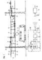
- FIG. 1 shows a monitoring device 10 for monitoring in particular the thermal load of a conductor 2 represented in the form of a catenary of a railway catenary
- FIG. 8 shows a monitoring device 10 for monitoring in particular the thermal load of a conductor 2 shows.
- the overhead line 2 is used to power a Rail traction vehicle 31 via a current collector 32nd
- the overhead line 2 consists essentially of current-carrying Components such as feed line (not shown in Figure 1), carrying cable 22, contact wire 21, and various auxiliary elements such as hangers 23 and mating fasteners 24 for example in the form of clamps or thimbles.
- a plurality of masts 30 are provided for mounting the overhead line 2.
- the contact wire 21 is the operation of the rail traction vehicle 31 required power of, for example, 12 MW and more to the location of the current collector 32 (pantograph) of the railcar 31 transported.
- the contact wire 21 is with a (not shown in Figures 1 and 8) transverse to the contact wire 21 arranged grinding bar of the current collector 32 in Sliding contact.
- the sanding strip is doing with a certain Force, the so-called contact force, against the contact wire 21 pressed. This will be one for the electrical energy supply sufficient electrical contact between contact wire 21 and pantograph 32 formed.
- At least one Catenary 2, which is responsible for a speed of the railcar 31 is designed by over 100 km / h, existing Support cable 22 has a carrying function and also serves in addition for power supply.
- a modern overhead line 2 which allows a very high speed, can for Power supply in addition to the contact wire 21 and the support cable 22nd
- other electrical (part) conductor for example in Form of a so-called reinforcing line, be provided.
- the FBG sensors 41 to 45 and 51 to 53 are in the example of Figure 1 with irregular intervals (optically serial to each other) inscribed in an optical waveguide 40. she are thus integral parts of the same.
- An institution with a plurality, in particular optically parallel to each other Fiber optic cables with integrated FBG sensors is also possible.
- the optical fiber 40 as shown in Figure 1 is a one-piece construction or a Structure of several, at least visually interconnected Subsections are selected.
- the force acting on the contact wire 21 force directions 8 is a coordinate system 80 with a x-, y- and z-axis applied.
- the force component in the z direction can be understood as the contact force.
- the Forces in the Y direction occur as transverse and cutting forces and are, for example, to the partial entrainment of the contact wire 21 in grooves of a defective contact strip.
- Cross and cutting forces also occur due to the zigzag arrangement of the contact wire 21 in the direction of travel on, when driving the rail traction vehicle 31 a transverse movement the contact wire 21 relative to the current collector 32 and entails a frictional force associated with it.
- the Forces in the x-direction are called longitudinal forces by the friction between the contact strip and contact wire 21 at Driving in the direction of travel caused.
- optical sensors 54 to 56 In the form of fiber Bragg grating (FBG) sensors intended.
- FBG fiber Bragg grating
- the distribution shown in Figure 8 this FBG sensors 54 to 56 are only examples. Other Sensor distributions are also possible.
- the single ones Measuring sections along the conductor 2 are each with a Sensor pair 54 to 56 provided in fiber optic strands are inscribed.
- Each sensor of a pair 54 to 56 is assigned to an optical fiber strand.
- the in Figure 8 illustrated optical waveguide 40 is thus as a double strand to understand. There are more at one location as two sensors, each one an optical fiber strand are assigned, conceivable.
- the fiber optic strands can while parts of a single optical waveguide 2 or be each also correspond to an optical waveguide 2. Of the or the optical waveguide 2 may be constructed in one piece or even from several at least visually with each other connected parts.
- Each of the FBG sensors 41 to 45 and 51 to 53 in Figure 1 and 54 to 56 in Fig. 2 has a specific centroid wavelength - the so-called Bragg wavelength - which differs from that the other FBG sensors 41-45 and 51-53 in Figure 1 and 54 to 56 in Figure 2 differs.
- the injected light signal LS a share with the respective center wavelength as a partial-reflection light signal reflected back. The remainder of the light signal
- LS passes through the respective sensor 41 to 45 and 51 to 53 in Figure 1 and 54 to 56 in Figure 2 and applies to the next sensor 41 to 45 and 51 to 53 in FIGS. 1 and 54 to 56 in Figure 2.
- the coupler 62 is then one of the FBG sensors 41 to 45 and 51 to 53 in FIGS. 1 and 54 to 56 in FIG 2 reflected light signal LS 'on, resulting from the partial-reflection light signals of the individual FBG sensors 41 to 45 and 51 to 53 in Figure 1 and 54 to 56 in Figure 2 composed.
- the pending at the coupler 62 reflected light signal LS ' is passed from the coupler 62 to an opto-electrical converter 63.
- the latter includes in particular a spectrally selective Element for selecting the individual partial-reflection light signals, for example in the form of a polychromator and an optionally also multi-part light receiver.
- a spectrally selective Element for selecting the individual partial-reflection light signals, for example in the form of a polychromator and an optionally also multi-part light receiver.
- to Analysis of the light spectrum are grating or diffraction spectrometers conceivable.
- Following the optoelectronic conversion finds in an A / D converter 64 an analog / digital conversion instead of.
- the digitized output signal of the A / D converter 64 is supplied to a digital evaluation unit 65, in the Measured values M1, M2, M3, M4, ...
- the coupler 62 is at one End of the optical waveguide 40 and the optical waveguide 40th the light signal LS coupled by means of the light source 61 and at the other end of the optical waveguide 40 and the optical waveguide 40 detected by an opto-electrical converter 63.
- the light source 61, the coupler 62, the opto-electrical converter 63, the A / D converter 64 and the evaluation unit 65 are in a transmitting / receiving unit 60, wherein the subunit from light source 61 and coupler 62 as means for Feeding the light signal LS into the FBG sensors 41 to 45 and 51 to 53 in Figure 1 and 54 to 56 in Figure 2 and the Subunit of optoelectric transducer 63, A / D converter 64 and evaluation unit 65 as means for determining a measured value M1, M2, M3, M4, ... for the FBG sensors 41 to 45 and 51 to 53 in Figure 1 and 54 to 56 in Figure 2, respectively can be understood.
- these subunits or parts of it are structurally separated, that is, not as a common transmitting / receiving unit 60, be educated.
- a purely analog evaluation for example by means of a hard-wired electronic Circuit possible. Then no A / D converter 64 would be present and the evaluation unit 65 realized analogously.
- the transmitting / receiving unit 60 of each in Figure 1 and FIG 8 is at ground potential, where however, the overhead line 2 on a in the railway energy supply usual potential, in particular from 15 to 25 kV, lies.
- the bridging of this potential difference takes place by means of the optical waveguide 40 or the optical waveguide 40, via the / the also fed light signal LS and the reflected light signal LS 'are transmitted.
- the optical fiber (s) 40 consists of a dielectric material, such as glass or plastic. This is no separate measures for electrical insulation required.
- the generated in the respective transmitting / receiving unit 60 Measured values M1, M2, M3, M4,... In FIG. 1 and FIG by means of a radio transmission to a data acquisition unit 90 transmitted.
- the data transfer can basically also wired electrical or optical'er réelle.
- the transmitting / receiving unit 60 and the data acquisition unit 90 also formed as a common entity be.
- control unit 70 in Figure 1 is a protection concept deposited for the overhead line 2.
- a protective measure for the Catenary 2 is to be initiated.
- the Current flow in the overhead line 2 can be reduced to the overhead line 2 in case of too high thermal or mechanical To protect stress from destruction. in the In extreme cases, the overhead line 2 can also be switched off become.
- These measures are taken over by the control unit 70 generated control signal CS initiated.
- the determined overstress causes the control signal CS in a switching unit, not shown in Figure 1 For example, a reduction of the current flow.
- FIG. 8 shows a further transceiver unit 95, with the data D31 to identify the in the "Quality Gate" received 11 incoming railcars become.
- the transmitting / receiving unit 33 may for example be designed such that their operating energy from one of the transmitting / receiving unit 95 radiated electromagnetic field 96 refers. In principle, it is also conceivable to transfer the data to make optical ways.
- the obtained railway traction vehicle data are passed on by the transmitting / receiving unit 95 transmitted to the data acquisition unit 90 and together with the corresponding, transmitted by the transmitting / receiving unit 60 Measured values M3, M4, ... stored.
- the one for the Catenary 2 responsible infrastructure operators thus has also at a later date the opportunity to be recorded and assigned to the individual rail traction vehicles To access measured values.
- the from the transmitting / receiving unit 60 to the data acquisition unit 90 transmitted measured values M3, M4, ... are above in addition by means of a radio transmission to a control unit 70 transmitted.
- the data transfer can basically also conducted by wire electrical or optical.
- the transmitting / receiving units 60 and 95, the Data acquisition unit 90 and the control unit 70 also as be formed common entity.
- control unit 70 is a protection concept for the overhead line 2 deposited. Depending on the size of the measured values M3, M4, ... for the actual mechanical load is decided in the control unit 70, if a Protective measure for the overhead line 2 is to be initiated. Especially can the current collector from the 32 on the overhead line. 2 acting force is reduced or increased to the catenary 2 in case of excessive mechanical load before one To protect destruction. These measures will be over initiated by the control unit 70 control signal CS initiated for example by radio transmission to the railcar 31 is sent. In addition, the railcar driver can the his railcar 31 assigned measured data M3, M4, ... transmitted by radio transmission so that he has the opportunity, if necessary rules intervene.
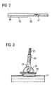
- Figures 2 to 7 are ways to attach the FBG sensors 41 to 45 and 51 to 53 on or in the components the overhead line 2 shown.
- the FBG sensor 41 is shown in FIG. 2 as executed in a housing 55 embedded sensor 59.
- the Optical fiber 40 is located with the integrated FBG sensor 41 itself in a for example round housing, whereby the optical fiber 40 and the FBG sensor 41 to rough Environmental conditions is protected and also a mechanical Decoupling of the FBG sensor 41 from the component to be monitored Catenary 2, on or in the embedded one Sensor 59 is to be attached to ensure.
- a mechanical decoupling is advantageous. In difference this would be in an FBG strain sensor 51 to 53 just one non-positive coupling with the component to be monitored the overhead line 2 sought (positive connection).
- a sensor network as shown in Figure 1 and Figure 8,
- the sensor 59 may be last Sensor used in the light path.
- the sensor 59 in particular in connection with a coupler 62 comparable Element also at any point in the sensor network of Figure 1 and Figure 8 are used.
- a transmissive embodiment possible.
- Then 55 is on the right edge of the housing of the sump or reflector close an outlet for the optical waveguide 40 is provided.
- FIG. 3 is shown schematically how two embedded Sensors 59 according to FIG. 2 on connecting elements 24 and 25 the overhead line 2 are attached.
- the element 24 as a plug-in clamp for attaching the trailer 23rd executed on the contact wire 21.
- the element 25, however, is a Kausche with notch connector.
- the FBG sensors 41 to 45 and 51 to 53 also on other connecting elements attach the overhead line 2.
- Examples of other such attaching an FBG sensor 41 to 45 and 51 to 53 suitable fasteners For example, a tooth clamp, a power terminal for the Support cable 22 or the contact wire 21, a screw-clamp for attachment of the trailer 23 on the support cable 22 or on the contact wire 21, a trolley jumper or a bridge clamp.
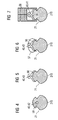
- Figures 4 to 7 are ways to arrange the Optical waveguide 40 including the example selected FBG sensors 41 to 43 shown in or on the contact wire 21.
- the attachment is in each case preferably on or in a region of the contact wire 21, that of a contact side 210 is opposite.
- the contact side 210 is used for sliding contact of the contact wire 21 with the current collector 32nd für the attachment in one of the contact side 210 opposite Range is the mechanical load of the optical fiber 40 kept as low as possible. simultaneously the FBG sensors 41 to 43 are still very close at the actually interesting measuring point, namely at the thermally highly charged contact side 210.
- This accommodation is very space saving.
- the outer dimensions of the overhead line 2 are at this Type of attachment of the optical waveguide 40 and the sensor 42 virtually unchanged.
- the optical fiber 40 with the FBG sensors 43 and 41 is the optical fiber 40 with the FBG sensors 43 and 41, however, not in the contact wire 21 itself, but in an additional provided receiving element 56, for example be designed as an adapter made of copper or a plastic can, arranged.
- the receiving element 56 then contains a Hollow channel in which the optical fiber 40 including FBG sensors 43 and 41 is relocated.
- the receiving element 56 but also positively around the optical fiber 40 and the FBG sensors 43 and 41 may be arranged.
- One such positive fit results in particular when used a customary in plastics processing manufacturing process, for example, a spraying and / or casting process.
- the receiving element 56 is in the embodiment of FIG 5 glued or soldered to the contact wire 21 and in the Embodiments of Figures 6 and 7 on the contact wire 21st clamped.
- the clamp connection is made as shown of Figure 6 by means of an additionally provided clamping device 57, whereas in the embodiment of FIG the clamp connection by means of an already existing clamping device 58 is realized.
- the to accommodate the Receiving member 56 certain cavity within the clamping device 58 can - as in the example of Figure 7 - anyway to be available. But he can also by targeted change the constructive elements of the clamping device 58th have been introduced. Furthermore, in the example of FIG 6 instead of the clamping device 57, a screw connection be provided.
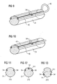
- FIG. 9 shows an exemplary embodiment with an optical waveguide 40, while in Figure 10, an FBG sensor each in a Optical waveguide 40 is arranged.
- the FBG sensor pairs 40 parallel to each other on the same Length of the conductor to be examined 2, as in the two figures represented, arranged.
- FIGS. 11 to 13 show, on the basis of contact wire cross-sections, at which points FBG sensors 54 to 56 are preferably arranged become.
- FIG. 12 shows an embodiment, in which two FBG sensors 54 laterally in each case a groove 211 are arranged.
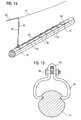
- FIG 14 is a contact wire section 21 with a contact wire 21 mounted optical fiber 40 shown.
- the optical waveguide 40 with a "Single-ended" sensor 47 executed. It can be seen, in that the optical waveguide 40 is connected by means of connections 81, in particular clamping and / or screw, on the contact wire 21 is guided along and the end of the optical waveguide 40 with the optical sensor 47 of another Clamping and / or screw 82 or 83 on the contact wire 21st is attached.
- connections 81 in particular clamping and / or screw
- Figure 15 shows a clamping connection 81, which by a on a Biasing means 84, for example a screw with nut, introduced bias on the contact wire 21 is fixed.
- a Biasing means 84 for example a screw with nut
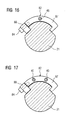
- Figure 16 shows one of a flange 88 and a bow-shaped Body 87 existing two-piece clamp connection 82, the also by a biasing means 84, for example a screw, introduced bias on the contact wire 21 is fixed.
- the clamping connection 82 is designed such that they form-fit on the top of the contact wire 21 can be arranged.
- the optical waveguide 40th with the optical sensor 46 has thereby also through the positive locking, in particular in a bore of Clamping connection 82, force and / or heat-sealing contact with the contact wire 21.
- Figure 17 further shows a corresponding embodiment, with the two optical fibers 40 with optical sensor 46 recorded can be.
- Conceivable are also the embodiments can accommodate more than two optical fibers 40.
- the maximal Number of the receivable optical fiber 40 depends essentially the dimensions of the corresponding clamping connection 82 and the diameters of the optical waveguides 40th from.
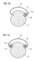
- an exemplary embodiment 83 is one of each Clamping connection shown without additional biasing means 84, such as screws, manages.
- Both shown clamping connections 83 consist of a or two receiving elements 86, wherein each receiving element 86 is in each case provided in particular with a bore and in the form-fitting and thus power and / or heat-dissipating in each case an optical waveguide 40 are arranged can.
- the two clamp connections 83 in each case an elastic strap 85, in particular a leaf spring. With the help of the leaf spring 85, a bias voltage such be constructed that the respective clamping connection 83 without additional biasing means 84 are fixed to the contact wire can.
- FIGS. 16 and 18 are designed in this way that they form-fit contact with the already design-related existing recess of the contact wire 21st to have. This ultimately provides a force and / or heat-conclusive Contact of the optical sensor 46 and the optical Sensors 46 with the contact wire 21.
- the assembly of the clamping connections 83 is very simple, since they only on the contact wire 21 "must be clipped".
- the embodiments shown in FIGS. 16 and 18 are preferably for temperature and strain monitoring while those shown in FIGS. 17 and 19 are used Embodiments with their two optical Sensors 46 preferably for determining the outside of the contact wire
- FIGS. 1 and 8 can be easily combined. So can together with the supervision of the mechanical load always the supervision the thermal load of the monitored control components be performed. This underlines particularly the advantageous flexibility and compatibility of both in the figures 1 and 8 devices shown.
Landscapes
- Engineering & Computer Science (AREA)
- Manufacturing & Machinery (AREA)
- Mechanical Engineering (AREA)
- Physics & Mathematics (AREA)
- General Physics & Mathematics (AREA)
- Length Measuring Devices By Optical Means (AREA)
- Current-Collector Devices For Electrically Propelled Vehicles (AREA)
- Gas-Insulated Switchgears (AREA)
- Force Measurement Appropriate To Specific Purposes (AREA)
Applications Claiming Priority (6)
| Application Number | Priority Date | Filing Date | Title |
|---|---|---|---|
| DE10321790 | 2003-05-14 | ||
| DE10321790 | 2003-05-14 | ||
| DE102004015875 | 2004-03-31 | ||
| DE102004015875 | 2004-03-31 | ||
| DE102004016741 | 2004-04-05 | ||
| DE102004016741 | 2004-04-05 |
Publications (2)
| Publication Number | Publication Date |
|---|---|
| EP1496369A1 true EP1496369A1 (fr) | 2005-01-12 |
| EP1496369B1 EP1496369B1 (fr) | 2008-04-09 |
Family
ID=33457983
Family Applications (1)
| Application Number | Title | Priority Date | Filing Date |
|---|---|---|---|
| EP04010128A Expired - Lifetime EP1496369B1 (fr) | 2003-05-14 | 2004-04-28 | Procédé et appareil optique pour surveiller un conducteur électrique |
Country Status (4)
| Country | Link |
|---|---|
| EP (1) | EP1496369B1 (fr) |
| AT (1) | ATE391919T1 (fr) |
| DE (2) | DE102004020324A1 (fr) |
| ES (1) | ES2304564T3 (fr) |
Cited By (16)
| Publication number | Priority date | Publication date | Assignee | Title |
|---|---|---|---|---|
| WO2006114562A1 (fr) * | 2005-04-27 | 2006-11-02 | Morganite Electrical Carbon Limited | Systeme de surveillance pour des vehicules electriques tirant un courant de conducteurs |
| EP1717567A1 (fr) * | 2005-04-29 | 2006-11-02 | Siemens Aktiengesellschaft | Dispositif de mesure de force destiné à la détermination d'une force de contact |
| FR2904687A1 (fr) * | 2006-08-01 | 2008-02-08 | Commissariat Energie Atomique | Dispositif de mesure des deformations d'un profile soumis a un ou plusieurs efforts |
| WO2008070766A2 (fr) * | 2006-12-07 | 2008-06-12 | University Of Florida Research Foundation, Inc. | Procédé et système de détection d'anomalies de fibre optique dans les lignes de transport d'électricité souterraines |
| FR2924499A1 (fr) * | 2007-12-03 | 2009-06-05 | Faiveley Transp Tours Soc Par | Installation de mesure pour le comptage d'energie d'alimentation d'un materiel roulant |
| WO2010006824A1 (fr) * | 2008-07-14 | 2010-01-21 | Siemens Aktiengesellschaft | Procédé de construction d’une installation de ligne aérienne et installation de ligne aérienne ainsi construite |
| WO2010119095A1 (fr) | 2009-04-15 | 2010-10-21 | Sintef | Surveillance de la température d'une ligne électrique aérienne |
| CN101452628B (zh) * | 2007-12-04 | 2011-09-14 | 淄博智洋电气有限公司 | 电气化铁路接触网温度在线监测系统 |
| CN102288350A (zh) * | 2011-06-30 | 2011-12-21 | 李丰良 | 一种接触网定位管传感器 |
| WO2013045242A3 (fr) * | 2011-09-29 | 2014-01-16 | Siemens Aktiengesellschaft | Installation de caténaire destinée à alimenter en traction un véhicule moteur électrique |
| EP2857256A1 (fr) * | 2013-10-02 | 2015-04-08 | Nearic Business Solutions | Système de réseau |
| AT14113U1 (de) * | 2013-12-10 | 2015-04-15 | Karl U Albert Kruch Ges M B H & Co Kg Ing | Vorrichtung zum Ausgleich von temperaturbedingten Längenänderungen von Fahrleitungen elektrischer Bahnen |
| US9746393B2 (en) | 2012-06-29 | 2017-08-29 | Optasense Holdings Limited | Fibre optic sensing |
| EP3693207A1 (fr) * | 2019-02-11 | 2020-08-12 | Lef Holding S.r.l. | Système pour le chauffage des caténaires de lignes de chemin de fer électrifiés |
| CN112129445A (zh) * | 2020-09-27 | 2020-12-25 | 中国科学院力学研究所 | 一种弓网接触力在线测试方案 |
| CN112378428A (zh) * | 2020-09-18 | 2021-02-19 | 云南电网有限责任公司昭通供电局 | 一种光纤复合架空地线融冰通流过程弧垂实时监测装置及方法 |
Families Citing this family (8)
| Publication number | Priority date | Publication date | Assignee | Title |
|---|---|---|---|---|
| DE102004055524A1 (de) | 2004-11-17 | 2006-05-24 | Siemens Ag | Optisches Verfahren und optische Einrichtung zur Überwachung eines elektrischen Leiters |
| DE102005017797B4 (de) * | 2005-04-13 | 2010-10-28 | Fachhochschule Jena | Schweissanordnung, insbesondere zum Verbinden von Werkstücken durch Widerstands- oder Pressschweissen |
| DE102005057404A1 (de) * | 2005-11-30 | 2007-06-06 | Deutsche Bahn Ag | Fiberoptische Messung von Positionen und Kräften an Fahrleitungen und/oder Stromabnehmern, die durch Stromabnehmer hervorgerufen werden |
| DE102006016644A1 (de) * | 2006-04-08 | 2007-10-11 | Dürr Systems GmbH | Vorrichtung zum Zuführen von Medien zu Bearbeitungsplätzen |
| DE102009057877B4 (de) | 2009-12-11 | 2016-03-03 | Deutsche Bahn Ag | Verfahren und Vorrichtung zur bildgebenden, optischen Messung von Kräften, Auslenkungen, Rotationen und Verwindungen in Fahrleitungen elektrisch betriebenen Verkehrs |
| RU2011118415A (ru) | 2011-05-06 | 2012-11-20 | Сименс Акциенгезелльшафт (DE) | Способ мониторинга железных дорог на основе волоконной оптики |
| DE102016116396A1 (de) | 2016-09-01 | 2018-03-15 | Conductix-Wampfler Gmbh | Schleifleitung, Stromabnehmer, Schleifleitungssystem und Verfahren zur berührungslosen Datenübertragung |
| DE102019120927A1 (de) * | 2019-09-23 | 2021-03-25 | Kromberg & Schubert Gmbh & Co. Kg | Funktionsmodell Leitungsdiagnose |
Citations (2)
| Publication number | Priority date | Publication date | Assignee | Title |
|---|---|---|---|---|
| US5493390A (en) * | 1993-09-06 | 1996-02-20 | Finmeccanica S.P.A.-Ramo Aziendale Alenia | Integrated optical instrumentation for the diagnostics of parts by embedded or surface attached optical sensors |
| WO2000068657A1 (fr) * | 1999-05-06 | 2000-11-16 | Leiv Eiriksson Nyfotek As | Systeme de surveillance de cables |
-
2004
- 2004-04-26 DE DE102004020324A patent/DE102004020324A1/de not_active Ceased
- 2004-04-28 ES ES04010128T patent/ES2304564T3/es not_active Expired - Lifetime
- 2004-04-28 DE DE502004006752T patent/DE502004006752D1/de not_active Expired - Fee Related
- 2004-04-28 EP EP04010128A patent/EP1496369B1/fr not_active Expired - Lifetime
- 2004-04-28 AT AT04010128T patent/ATE391919T1/de not_active IP Right Cessation
Patent Citations (2)
| Publication number | Priority date | Publication date | Assignee | Title |
|---|---|---|---|---|
| US5493390A (en) * | 1993-09-06 | 1996-02-20 | Finmeccanica S.P.A.-Ramo Aziendale Alenia | Integrated optical instrumentation for the diagnostics of parts by embedded or surface attached optical sensors |
| WO2000068657A1 (fr) * | 1999-05-06 | 2000-11-16 | Leiv Eiriksson Nyfotek As | Systeme de surveillance de cables |
Non-Patent Citations (2)
| Title |
|---|
| ARAUJO F M ET AL: "SURVEILLANCE OF FIBER OPTIC CABLES AND ELECTRIC POWER CABLES USING FIBER BRAGG GRATING SENSORS", PROCEEDINGS OF THE SPIE, SPIE, BELLINGHAM, VA, US, vol. 3541, November 1998 (1998-11-01), pages 278 - 289, XP002931504, ISSN: 0277-786X * |
| KALINOWSKI H J ET AL: "MULTIPLEXED FIBER OPTICS BRAGG GRATING SENSORS FOR STRAIN AND TEMPERATURE MEASUREMENTS IN POWER SYSTEMS", PROCEEDINGS OF THE SPIE, SPIE, BELLINGHAM, VA, US, vol. 3666, 1999, pages 544 - 553, XP002931503, ISSN: 0277-786X * |
Cited By (22)
| Publication number | Priority date | Publication date | Assignee | Title |
|---|---|---|---|---|
| WO2006114562A1 (fr) * | 2005-04-27 | 2006-11-02 | Morganite Electrical Carbon Limited | Systeme de surveillance pour des vehicules electriques tirant un courant de conducteurs |
| EP1717567A1 (fr) * | 2005-04-29 | 2006-11-02 | Siemens Aktiengesellschaft | Dispositif de mesure de force destiné à la détermination d'une force de contact |
| FR2904687A1 (fr) * | 2006-08-01 | 2008-02-08 | Commissariat Energie Atomique | Dispositif de mesure des deformations d'un profile soumis a un ou plusieurs efforts |
| EP1887316A1 (fr) | 2006-08-01 | 2008-02-13 | Commissariat A L'energie Atomique | Dispositif de mesure des déformations d'un profile soumis à un ou plusieurs efforts |
| US8022708B2 (en) | 2006-12-07 | 2011-09-20 | University Of Florida Research Foundation, Inc. | Fiber optic fault detection system and method for underground power lines |
| WO2008070766A2 (fr) * | 2006-12-07 | 2008-06-12 | University Of Florida Research Foundation, Inc. | Procédé et système de détection d'anomalies de fibre optique dans les lignes de transport d'électricité souterraines |
| WO2008070766A3 (fr) * | 2006-12-07 | 2008-12-11 | Univ Florida | Procédé et système de détection d'anomalies de fibre optique dans les lignes de transport d'électricité souterraines |
| FR2924499A1 (fr) * | 2007-12-03 | 2009-06-05 | Faiveley Transp Tours Soc Par | Installation de mesure pour le comptage d'energie d'alimentation d'un materiel roulant |
| CN101452628B (zh) * | 2007-12-04 | 2011-09-14 | 淄博智洋电气有限公司 | 电气化铁路接触网温度在线监测系统 |
| EP2296935B1 (fr) | 2008-07-14 | 2020-06-24 | Siemens Mobility GmbH | Installation de ligne aérienne |
| WO2010006824A1 (fr) * | 2008-07-14 | 2010-01-21 | Siemens Aktiengesellschaft | Procédé de construction d’une installation de ligne aérienne et installation de ligne aérienne ainsi construite |
| WO2010119095A1 (fr) | 2009-04-15 | 2010-10-21 | Sintef | Surveillance de la température d'une ligne électrique aérienne |
| NO333161B1 (no) * | 2009-04-15 | 2013-03-18 | Sintef | Overvaking av temperatur pa hoyspentlinje |
| CN102288350A (zh) * | 2011-06-30 | 2011-12-21 | 李丰良 | 一种接触网定位管传感器 |
| WO2013045242A3 (fr) * | 2011-09-29 | 2014-01-16 | Siemens Aktiengesellschaft | Installation de caténaire destinée à alimenter en traction un véhicule moteur électrique |
| CN103842206A (zh) * | 2011-09-29 | 2014-06-04 | 西门子公司 | 用于电力机动车辆的牵引供电的滑接线路设备 |
| US9746393B2 (en) | 2012-06-29 | 2017-08-29 | Optasense Holdings Limited | Fibre optic sensing |
| EP2857256A1 (fr) * | 2013-10-02 | 2015-04-08 | Nearic Business Solutions | Système de réseau |
| AT14113U1 (de) * | 2013-12-10 | 2015-04-15 | Karl U Albert Kruch Ges M B H & Co Kg Ing | Vorrichtung zum Ausgleich von temperaturbedingten Längenänderungen von Fahrleitungen elektrischer Bahnen |
| EP3693207A1 (fr) * | 2019-02-11 | 2020-08-12 | Lef Holding S.r.l. | Système pour le chauffage des caténaires de lignes de chemin de fer électrifiés |
| CN112378428A (zh) * | 2020-09-18 | 2021-02-19 | 云南电网有限责任公司昭通供电局 | 一种光纤复合架空地线融冰通流过程弧垂实时监测装置及方法 |
| CN112129445A (zh) * | 2020-09-27 | 2020-12-25 | 中国科学院力学研究所 | 一种弓网接触力在线测试方案 |
Also Published As
| Publication number | Publication date |
|---|---|
| DE502004006752D1 (de) | 2008-05-21 |
| DE102004020324A1 (de) | 2005-03-10 |
| ATE391919T1 (de) | 2008-04-15 |
| EP1496369B1 (fr) | 2008-04-09 |
| ES2304564T3 (es) | 2008-10-16 |
Similar Documents
| Publication | Publication Date | Title |
|---|---|---|
| EP1496369B1 (fr) | Procédé et appareil optique pour surveiller un conducteur électrique | |
| EP3069952B1 (fr) | Procédé de comptage d'axe et dispositif compteur d'axe | |
| EP1759914B1 (fr) | Méthode pour déterminer l'état d'un capteur de courant | |
| DE10249896A1 (de) | Verfahren und Einrichtung zur Messung der Kontaktkraft eines Stromabnehmers | |
| WO2009037271A1 (fr) | Capteur à fibres optiques pour mesurer les déformations sur les éoliennes | |
| DE102006041461A1 (de) | Windenergieanlage mit einer Windgeschwindigkeitsmessvorrichtung zur Bestimmung einer Geschwindigkeit des die Windenergieanlage anströmenden Windes | |
| EP1726473B1 (fr) | Dispositif pour mesurer une force et méthode pour la détermination d'une force transversale | |
| EP2246681B1 (fr) | Dispositif de mesure des forces entre une roue et un rail, notamment ensemble de roue de mesure pour véhicules sur rails | |
| EP2838752B1 (fr) | Procede et dispositif de détection de défaillance de pantographes | |
| DE19738651A1 (de) | Vorrichtung zur Ermittlung der Temperatur eines Objekts und Verfahren zur Herstellung einer solchen Vorrichtung | |
| EP1839990B1 (fr) | Dispositif pour la vérification des roues d'un véhicule ferroviaire | |
| DE102005057404A1 (de) | Fiberoptische Messung von Positionen und Kräften an Fahrleitungen und/oder Stromabnehmern, die durch Stromabnehmer hervorgerufen werden | |
| DE102005020125B3 (de) | Kraftmesseinrichtung zur Bestimmung einer Kontaktkraft | |
| EP1726472B1 (fr) | Dispositif de mesure d'une force et méthode pour la détermination d'une force de contact | |
| DE102009024518A1 (de) | Automatisierungseinheit in fördertechnischen Anlagen | |
| EP1659019B1 (fr) | Méthode et système optique pour le contrôle d'une ligne électrique | |
| DE102016202662A1 (de) | Einrichtung zur faserbasierten Temperaturdetektion | |
| DE102016207312A1 (de) | Messvorrichtung und Verfahren zur Messung eines Verschleißzustandes | |
| DE102009057877B4 (de) | Verfahren und Vorrichtung zur bildgebenden, optischen Messung von Kräften, Auslenkungen, Rotationen und Verwindungen in Fahrleitungen elektrisch betriebenen Verkehrs | |
| DE102006002084A1 (de) | Optische Einrichtung zur Ermittlung einer Kontaktkraft eines Stromabnehmers eines Schienentriebfahrzeugs auf einen Fahrdraht | |
| EP3571089A1 (fr) | Procédé et dispositif de mesure pour la détermination de l'usure d'une caténaire dans une installation technique de transport | |
| DE102017204034B3 (de) | Vorrichtung und Verfahren zum Testen eines zu überprüfenden Lichtwellenleiters | |
| DE102021114425A1 (de) | Messradsatz | |
| WO1999066293A1 (fr) | Systeme d'acheminement de donnes par fibres optiques et procede pour le fonctionnement d'un tel systeme | |
| WO2000028284A1 (fr) | Dispositif de mesure optique |
Legal Events
| Date | Code | Title | Description |
|---|---|---|---|
| PUAI | Public reference made under article 153(3) epc to a published international application that has entered the european phase |
Free format text: ORIGINAL CODE: 0009012 |
|
| AK | Designated contracting states |
Kind code of ref document: A1 Designated state(s): AT BE BG CH CY CZ DE DK EE ES FI FR GB GR HU IE IT LI LU MC NL PL PT RO SE SI SK TR |
|
| AX | Request for extension of the european patent |
Extension state: AL HR LT LV MK |
|
| 17P | Request for examination filed |
Effective date: 20050207 |
|
| 17Q | First examination report despatched |
Effective date: 20050303 |
|
| AKX | Designation fees paid |
Designated state(s): AT BE BG CH CY CZ DE DK EE ES FI FR GB GR HU IE IT LI LU MC NL PL PT RO SE SI SK TR |
|
| 17Q | First examination report despatched |
Effective date: 20050303 |
|
| GRAP | Despatch of communication of intention to grant a patent |
Free format text: ORIGINAL CODE: EPIDOSNIGR1 |
|
| GRAS | Grant fee paid |
Free format text: ORIGINAL CODE: EPIDOSNIGR3 |
|
| GRAA | (expected) grant |
Free format text: ORIGINAL CODE: 0009210 |
|
| AK | Designated contracting states |
Kind code of ref document: B1 Designated state(s): AT BE BG CH CY CZ DE DK EE ES FI FR GB GR HU IE IT LI LU MC NL PL PT RO SE SI SK TR |
|
| REG | Reference to a national code |
Ref country code: GB Ref legal event code: FG4D Free format text: NOT ENGLISH |
|
| REG | Reference to a national code |
Ref country code: CH Ref legal event code: EP |
|
| REG | Reference to a national code |
Ref country code: IE Ref legal event code: FG4D Free format text: LANGUAGE OF EP DOCUMENT: GERMAN |
|
| REF | Corresponds to: |
Ref document number: 502004006752 Country of ref document: DE Date of ref document: 20080521 Kind code of ref document: P |
|
| REG | Reference to a national code |
Ref country code: CH Ref legal event code: NV Representative=s name: SIEMENS SCHWEIZ AG |
|
| REG | Reference to a national code |
Ref country code: SE Ref legal event code: TRGR |
|
| PG25 | Lapsed in a contracting state [announced via postgrant information from national office to epo] |
Ref country code: SI Free format text: LAPSE BECAUSE OF FAILURE TO SUBMIT A TRANSLATION OF THE DESCRIPTION OR TO PAY THE FEE WITHIN THE PRESCRIBED TIME-LIMIT Effective date: 20080409 |
|
| NLV1 | Nl: lapsed or annulled due to failure to fulfill the requirements of art. 29p and 29m of the patents act | ||
| REG | Reference to a national code |
Ref country code: ES Ref legal event code: FG2A Ref document number: 2304564 Country of ref document: ES Kind code of ref document: T3 |
|
| BERE | Be: lapsed |
Owner name: IEMENS A.G. Effective date: 20080430 |
|
| PG25 | Lapsed in a contracting state [announced via postgrant information from national office to epo] |
Ref country code: NL Free format text: LAPSE BECAUSE OF FAILURE TO SUBMIT A TRANSLATION OF THE DESCRIPTION OR TO PAY THE FEE WITHIN THE PRESCRIBED TIME-LIMIT Effective date: 20080409 Ref country code: BG Free format text: LAPSE BECAUSE OF FAILURE TO SUBMIT A TRANSLATION OF THE DESCRIPTION OR TO PAY THE FEE WITHIN THE PRESCRIBED TIME-LIMIT Effective date: 20080709 Ref country code: FI Free format text: LAPSE BECAUSE OF FAILURE TO SUBMIT A TRANSLATION OF THE DESCRIPTION OR TO PAY THE FEE WITHIN THE PRESCRIBED TIME-LIMIT Effective date: 20080409 Ref country code: PT Free format text: LAPSE BECAUSE OF FAILURE TO SUBMIT A TRANSLATION OF THE DESCRIPTION OR TO PAY THE FEE WITHIN THE PRESCRIBED TIME-LIMIT Effective date: 20080909 |
|
| PG25 | Lapsed in a contracting state [announced via postgrant information from national office to epo] |
Ref country code: PL Free format text: LAPSE BECAUSE OF FAILURE TO SUBMIT A TRANSLATION OF THE DESCRIPTION OR TO PAY THE FEE WITHIN THE PRESCRIBED TIME-LIMIT Effective date: 20080409 Ref country code: MC Free format text: LAPSE BECAUSE OF NON-PAYMENT OF DUE FEES Effective date: 20080430 |
|
| REG | Reference to a national code |
Ref country code: IE Ref legal event code: FD4D |
|
| ET | Fr: translation filed | ||
| PG25 | Lapsed in a contracting state [announced via postgrant information from national office to epo] |
Ref country code: CZ Free format text: LAPSE BECAUSE OF FAILURE TO SUBMIT A TRANSLATION OF THE DESCRIPTION OR TO PAY THE FEE WITHIN THE PRESCRIBED TIME-LIMIT Effective date: 20080409 Ref country code: DK Free format text: LAPSE BECAUSE OF FAILURE TO SUBMIT A TRANSLATION OF THE DESCRIPTION OR TO PAY THE FEE WITHIN THE PRESCRIBED TIME-LIMIT Effective date: 20080409 Ref country code: EE Free format text: LAPSE BECAUSE OF FAILURE TO SUBMIT A TRANSLATION OF THE DESCRIPTION OR TO PAY THE FEE WITHIN THE PRESCRIBED TIME-LIMIT Effective date: 20080409 Ref country code: IE Free format text: LAPSE BECAUSE OF FAILURE TO SUBMIT A TRANSLATION OF THE DESCRIPTION OR TO PAY THE FEE WITHIN THE PRESCRIBED TIME-LIMIT Effective date: 20080409 |
|
| PLBE | No opposition filed within time limit |
Free format text: ORIGINAL CODE: 0009261 |
|
| STAA | Information on the status of an ep patent application or granted ep patent |
Free format text: STATUS: NO OPPOSITION FILED WITHIN TIME LIMIT |
|
| PG25 | Lapsed in a contracting state [announced via postgrant information from national office to epo] |
Ref country code: SK Free format text: LAPSE BECAUSE OF FAILURE TO SUBMIT A TRANSLATION OF THE DESCRIPTION OR TO PAY THE FEE WITHIN THE PRESCRIBED TIME-LIMIT Effective date: 20080409 Ref country code: RO Free format text: LAPSE BECAUSE OF FAILURE TO SUBMIT A TRANSLATION OF THE DESCRIPTION OR TO PAY THE FEE WITHIN THE PRESCRIBED TIME-LIMIT Effective date: 20080409 |
|
| 26N | No opposition filed |
Effective date: 20090112 |
|
| PG25 | Lapsed in a contracting state [announced via postgrant information from national office to epo] |
Ref country code: BE Free format text: LAPSE BECAUSE OF NON-PAYMENT OF DUE FEES Effective date: 20080430 |
|
| REG | Reference to a national code |
Ref country code: CH Ref legal event code: PCAR Free format text: SIEMENS SCHWEIZ AG;INTELLECTUAL PROPERTY FREILAGERSTRASSE 40;8047 ZUERICH (CH) |
|
| PGFP | Annual fee paid to national office [announced via postgrant information from national office to epo] |
Ref country code: ES Payment date: 20090512 Year of fee payment: 6 |
|
| PGFP | Annual fee paid to national office [announced via postgrant information from national office to epo] |
Ref country code: AT Payment date: 20090311 Year of fee payment: 6 Ref country code: FR Payment date: 20090424 Year of fee payment: 6 Ref country code: IT Payment date: 20090428 Year of fee payment: 6 Ref country code: SE Payment date: 20090407 Year of fee payment: 6 |
|
| PG25 | Lapsed in a contracting state [announced via postgrant information from national office to epo] |
Ref country code: CY Free format text: LAPSE BECAUSE OF FAILURE TO SUBMIT A TRANSLATION OF THE DESCRIPTION OR TO PAY THE FEE WITHIN THE PRESCRIBED TIME-LIMIT Effective date: 20080409 |
|
| PGFP | Annual fee paid to national office [announced via postgrant information from national office to epo] |
Ref country code: CH Payment date: 20090703 Year of fee payment: 6 Ref country code: DE Payment date: 20090619 Year of fee payment: 6 Ref country code: GB Payment date: 20090409 Year of fee payment: 6 |
|
| PG25 | Lapsed in a contracting state [announced via postgrant information from national office to epo] |
Ref country code: HU Free format text: LAPSE BECAUSE OF FAILURE TO SUBMIT A TRANSLATION OF THE DESCRIPTION OR TO PAY THE FEE WITHIN THE PRESCRIBED TIME-LIMIT Effective date: 20081010 Ref country code: LU Free format text: LAPSE BECAUSE OF NON-PAYMENT OF DUE FEES Effective date: 20080428 |
|
| PG25 | Lapsed in a contracting state [announced via postgrant information from national office to epo] |
Ref country code: TR Free format text: LAPSE BECAUSE OF FAILURE TO SUBMIT A TRANSLATION OF THE DESCRIPTION OR TO PAY THE FEE WITHIN THE PRESCRIBED TIME-LIMIT Effective date: 20080409 |
|
| PG25 | Lapsed in a contracting state [announced via postgrant information from national office to epo] |
Ref country code: GR Free format text: LAPSE BECAUSE OF FAILURE TO SUBMIT A TRANSLATION OF THE DESCRIPTION OR TO PAY THE FEE WITHIN THE PRESCRIBED TIME-LIMIT Effective date: 20080710 |
|
| EUG | Se: european patent has lapsed | ||
| REG | Reference to a national code |
Ref country code: CH Ref legal event code: PL |
|
| GBPC | Gb: european patent ceased through non-payment of renewal fee |
Effective date: 20100428 |
|
| REG | Reference to a national code |
Ref country code: FR Ref legal event code: ST Effective date: 20101230 |
|
| PG25 | Lapsed in a contracting state [announced via postgrant information from national office to epo] |
Ref country code: FR Free format text: LAPSE BECAUSE OF NON-PAYMENT OF DUE FEES Effective date: 20100430 Ref country code: AT Free format text: LAPSE BECAUSE OF NON-PAYMENT OF DUE FEES Effective date: 20100428 |
|
| PG25 | Lapsed in a contracting state [announced via postgrant information from national office to epo] |
Ref country code: CH Free format text: LAPSE BECAUSE OF NON-PAYMENT OF DUE FEES Effective date: 20100430 Ref country code: DE Free format text: LAPSE BECAUSE OF NON-PAYMENT OF DUE FEES Effective date: 20101103 Ref country code: LI Free format text: LAPSE BECAUSE OF NON-PAYMENT OF DUE FEES Effective date: 20100430 |
|
| PG25 | Lapsed in a contracting state [announced via postgrant information from national office to epo] |
Ref country code: GB Free format text: LAPSE BECAUSE OF NON-PAYMENT OF DUE FEES Effective date: 20100428 Ref country code: IT Free format text: LAPSE BECAUSE OF NON-PAYMENT OF DUE FEES Effective date: 20100428 |
|
| REG | Reference to a national code |
Ref country code: ES Ref legal event code: FD2A Effective date: 20110711 |
|
| PG25 | Lapsed in a contracting state [announced via postgrant information from national office to epo] |
Ref country code: ES Free format text: LAPSE BECAUSE OF NON-PAYMENT OF DUE FEES Effective date: 20110629 |
|
| PG25 | Lapsed in a contracting state [announced via postgrant information from national office to epo] |
Ref country code: ES Free format text: LAPSE BECAUSE OF NON-PAYMENT OF DUE FEES Effective date: 20100429 |
|
| PG25 | Lapsed in a contracting state [announced via postgrant information from national office to epo] |
Ref country code: SE Free format text: LAPSE BECAUSE OF NON-PAYMENT OF DUE FEES Effective date: 20100429 |