EP1496262A1 - Rotary compressor - Google Patents
Rotary compressor Download PDFInfo
- Publication number
- EP1496262A1 EP1496262A1 EP03707161A EP03707161A EP1496262A1 EP 1496262 A1 EP1496262 A1 EP 1496262A1 EP 03707161 A EP03707161 A EP 03707161A EP 03707161 A EP03707161 A EP 03707161A EP 1496262 A1 EP1496262 A1 EP 1496262A1
- Authority
- EP
- European Patent Office
- Prior art keywords
- casing
- partition member
- end plate
- trunk part
- housing
- Prior art date
- Legal status (The legal status is an assumption and is not a legal conclusion. Google has not performed a legal analysis and makes no representation as to the accuracy of the status listed.)
- Granted
Links
Images




Classifications
-
- F—MECHANICAL ENGINEERING; LIGHTING; HEATING; WEAPONS; BLASTING
- F04—POSITIVE - DISPLACEMENT MACHINES FOR LIQUIDS; PUMPS FOR LIQUIDS OR ELASTIC FLUIDS
- F04C—ROTARY-PISTON, OR OSCILLATING-PISTON, POSITIVE-DISPLACEMENT MACHINES FOR LIQUIDS; ROTARY-PISTON, OR OSCILLATING-PISTON, POSITIVE-DISPLACEMENT PUMPS
- F04C29/00—Component parts, details or accessories of pumps or pumping installations, not provided for in groups F04C18/00 - F04C28/00
-
- F—MECHANICAL ENGINEERING; LIGHTING; HEATING; WEAPONS; BLASTING
- F04—POSITIVE - DISPLACEMENT MACHINES FOR LIQUIDS; PUMPS FOR LIQUIDS OR ELASTIC FLUIDS
- F04C—ROTARY-PISTON, OR OSCILLATING-PISTON, POSITIVE-DISPLACEMENT MACHINES FOR LIQUIDS; ROTARY-PISTON, OR OSCILLATING-PISTON, POSITIVE-DISPLACEMENT PUMPS
- F04C23/00—Combinations of two or more pumps, each being of rotary-piston or oscillating-piston type, specially adapted for elastic fluids; Pumping installations specially adapted for elastic fluids; Multi-stage pumps specially adapted for elastic fluids
- F04C23/008—Hermetic pumps
-
- F—MECHANICAL ENGINEERING; LIGHTING; HEATING; WEAPONS; BLASTING
- F01—MACHINES OR ENGINES IN GENERAL; ENGINE PLANTS IN GENERAL; STEAM ENGINES
- F01C—ROTARY-PISTON OR OSCILLATING-PISTON MACHINES OR ENGINES
- F01C21/00—Component parts, details or accessories not provided for in groups F01C1/00 - F01C20/00
- F01C21/10—Outer members for co-operation with rotary pistons; Casings
-
- F—MECHANICAL ENGINEERING; LIGHTING; HEATING; WEAPONS; BLASTING
- F04—POSITIVE - DISPLACEMENT MACHINES FOR LIQUIDS; PUMPS FOR LIQUIDS OR ELASTIC FLUIDS
- F04C—ROTARY-PISTON, OR OSCILLATING-PISTON, POSITIVE-DISPLACEMENT MACHINES FOR LIQUIDS; ROTARY-PISTON, OR OSCILLATING-PISTON, POSITIVE-DISPLACEMENT PUMPS
- F04C18/00—Rotary-piston pumps specially adapted for elastic fluids
- F04C18/02—Rotary-piston pumps specially adapted for elastic fluids of arcuate-engagement type, i.e. with circular translatory movement of co-operating members, each member having the same number of teeth or tooth-equivalents
- F04C18/0207—Rotary-piston pumps specially adapted for elastic fluids of arcuate-engagement type, i.e. with circular translatory movement of co-operating members, each member having the same number of teeth or tooth-equivalents both members having co-operating elements in spiral form
- F04C18/0215—Rotary-piston pumps specially adapted for elastic fluids of arcuate-engagement type, i.e. with circular translatory movement of co-operating members, each member having the same number of teeth or tooth-equivalents both members having co-operating elements in spiral form where only one member is moving
-
- F—MECHANICAL ENGINEERING; LIGHTING; HEATING; WEAPONS; BLASTING
- F04—POSITIVE - DISPLACEMENT MACHINES FOR LIQUIDS; PUMPS FOR LIQUIDS OR ELASTIC FLUIDS
- F04C—ROTARY-PISTON, OR OSCILLATING-PISTON, POSITIVE-DISPLACEMENT MACHINES FOR LIQUIDS; ROTARY-PISTON, OR OSCILLATING-PISTON, POSITIVE-DISPLACEMENT PUMPS
- F04C2230/00—Manufacture
- F04C2230/20—Manufacture essentially without removing material
- F04C2230/23—Manufacture essentially without removing material by permanently joining parts together
- F04C2230/231—Manufacture essentially without removing material by permanently joining parts together by welding
-
- F—MECHANICAL ENGINEERING; LIGHTING; HEATING; WEAPONS; BLASTING
- F04—POSITIVE - DISPLACEMENT MACHINES FOR LIQUIDS; PUMPS FOR LIQUIDS OR ELASTIC FLUIDS
- F04C—ROTARY-PISTON, OR OSCILLATING-PISTON, POSITIVE-DISPLACEMENT MACHINES FOR LIQUIDS; ROTARY-PISTON, OR OSCILLATING-PISTON, POSITIVE-DISPLACEMENT PUMPS
- F04C2230/00—Manufacture
- F04C2230/60—Assembly methods
-
- F—MECHANICAL ENGINEERING; LIGHTING; HEATING; WEAPONS; BLASTING
- F04—POSITIVE - DISPLACEMENT MACHINES FOR LIQUIDS; PUMPS FOR LIQUIDS OR ELASTIC FLUIDS
- F04C—ROTARY-PISTON, OR OSCILLATING-PISTON, POSITIVE-DISPLACEMENT MACHINES FOR LIQUIDS; ROTARY-PISTON, OR OSCILLATING-PISTON, POSITIVE-DISPLACEMENT PUMPS
- F04C2240/00—Components
- F04C2240/30—Casings or housings
Definitions
- the present invention relates generally to a rotating compressor and, more particularly, pertains to a seal construction between a high-level pressure space and a low-level pressure space in the inside of a rotating compressor casing.
- Various types of compression mechanisms such as scroll type, swing type, and rolling piston type (i.e., rotary type) have been employed in conventional rotating compressors.
- Such a rotating compressor is used to compress a refrigerant gas in a refrigerating apparatus (e.g., an airconditioner) which executes a refrigerating cycle, as set forth for example in Japanese Patent Kokai No. (2000)97183.
- a compressor motor housed in the rotating compressor, serves as a drive source for activating a compression mechanism of the scroll, swing, or rolling piston type.
- the scroll compressor (100) is made up of a casing (101) , a compressor motor (102) , and a compression mechanism (103) .
- the casing (101) is made up of a trunk part (104) shaped like a cylinder and end plates (105, 106) secured firmly, by welding, to an upper and lower ends of the trunk part (104) , respectively.
- the compressor motor (102) is made up of a stator (107) secured firmly to the trunk part (104) and a rotor (108) disposed on the inner peripheral side of the stator (107) .
- a drive shaft (109) is coupled to the rotor (108) .
- the compression mechanism (103) has a fixed scroll, an orbiting scroll, and a housing all of which are not shown in the Figure, and the housing is secured firmly to the casing. In some cases, the fixed scroll is secured firmly to the casing. Additionally, the drive shaft (109) projects above and below the stator (107) and the rotor (108) . An upper end of the drive shaft (109) is connected to the orbiting scroll. On the other hand, a lower end of the drive shaft (109) is supported, through a bearing member (110) , on the casing (101) . Operations of the orbiting scroll accompanying the rotation of the drive shaft (109) cause variations in volume of a compression chamber, whereby the compression mechanism (103) performs operations of sucking, compressing, and discharging a refrigerant gas.
- the housing of the compression mechanism (103) is close-fitted, at its outer peripheral part, to the casing (101) , thereby defining spaces separated from each other, i.e., a space above the compression mechanism (103) and another below the compression mechanism (103), as set forth for example in Japanese Patent Kokai No. (1999)22661.
- the lower space is a high-level pressure space
- the upper space is a low-level pressure space.
- thermal insert In the conventional scroll compressor, generally the housing is secured firmly to the casing by thermal insert.
- thermal insert provides a structure of high sealability, it suffers problems with workability during the time that products are being assembled.
- an object of the present invention is to enhance not only workability during compressor assembling but also sealability between a high-level pressure space and a low-level pressure space in a casing in a rotating compressor, and to prevent the increase in costs.
- a peripheral groove (42) for allowing for shrinkage of a casing (10) at a weld area where a trunk part (11) of the casing (10) and an end plate (12) are welded together is formed in an outer peripheral surface (40) of a partition member (23) dividing the inside of the casing (10) into a high-level pressure space and a low-level pressure space, and the partition member (23) is tightened by making utilization of such shrinkage.
- an invention as set forth in claim 1 is directed to a rotating compressor comprising a casing (10) housing therein: a compressor motor (30) , a compression mechanism (20) which is driven by the compressor motor (30) , and a partition member (23) which divides the inside of the casing (10) into a high-level pressure space and a low-level pressure space, the casing (10) having a trunk part (11) shaped like a cylinder and an end plate (12) secured firmly to the trunk part (11) by welding.
- the rotating compressor is characterized in that the partition member (23) is so formed as to be press-fitted to the casing (10) at a weld area where the trunk part (11) and the end plate (12) are welded together or in the vicinity of the weld area, and a peripheral groove (42) extending continuously in a circumferential direction for allowing for shrinkage of the casing (10) caused by welding at the weld area of the trunk part (11) and the end plate (12) is formed in an outer peripheral surface (40) of the partition member (23).
- the “partition member (23) " of this structure may be a member to which a fixed scroll is attached or a fixed scroll itself for the case of a scroll compressor.
- the partition member (23) may be any member as long as it divides the inside of a casing into a high-level pressure space and a low-level pressure space, even for the case of a rotary or swing compressor.
- the trunk part (11) and the end plate (12) are welded together with the partition member (23) close-fitted, by press fitting, to the casing (10) (either the trunk part (11) or the end plate (12) ), the welding of the trunk part (11) and the end plate (12) causes the casing (10) to shrink at the peripheral groove (42) of the outer peripheral surface (40) of the partition member (23) .
- the partition member (23) Prior to welding, the partition member (23) is merely press-fitted to the casing (10) ; however, the act of welding causes the casing (10) to strongly tighten the partition member (23) in the vicinity of the peripheral groove (42) , thereby making it possible to provide sealability of the same level that thermal insert provides.
- An invention as set forth in claim 2 according to the rotating compressor of claim 1 is characterized in that a projection part (45)(46, 47) extending continuously in a circumferential direction at a position in proximity to the peripheral groove (42) is formed in the outer peripheral surface (40) of the partition member (23) , and that the projection part (45)(46, 47) is so formed as to be press-fitted to the casing (10) .
- the trunk part (11) and the end plate (12) are welded together, with the projection part (45)(46, 47) formed in the outer peripheral surface (40) of the partition member (23) press-fitted to the casing (10) (either the trunk part (11) or the end plate (12) ), thereby producing the same action as obtained by further increasing the margin for press-fitting of the projection part (45)(46, 47) to the trunk part (11) or to the end plate (12) , and the sealability is improved.
- the outer peripheral surface (40) of the partition member (23) is clearance-fitted to the trunk part (11) or end plate (12) of the casing (10) , and the peripheral groove (42) and the projection part (45)(46, 47) are formed in the outer peripheral surface (40) of the partition member (23) .
- this invention is characterized in that the partition member (23) is so formed as to be clearance-fitted to the casing (10) at a weld area where the trunk part (11) and the end plate (12) are welded together or in the vicinity of the weld area, that the peripheral groove (42) extending continuously in circumferential direction for allowing for shrinkage of the casing (10) caused by welding at the weld area of the trunk part (11) and the end plate (12) , and the projection part (45)(46, 47) extending continuously in circumferential direction at a position in proximity to the peripheral groove (42) are formed in the outer peripheral surface (40) of the partition member (23) , and that the projection part (45)(46, 47) is so formed as to be press-fitted to the casing (10) .
- an invention as set forth in claim 4 according to the rotating compressor of either claim 2 or claim 3 is characterized in that the projection part (46, 47) of the partition member (23) is provided at a plurality of areas.
- the projection part (46, 47) extending continuously in a circumferential direction in the outer peripheral surface (40) of the partition member (23) is provided in multiple in the axial direction of the partition member (23) , thereby providing an enhanced sealability because the number of points where the projection part (46, 47) is press-fitted to the trunk part (11) or to the end plate (12) increases.
- a fifth invention as set forth in claim 5 according to the rotating compressor of claim 4 is characterized in that the projection parts (46, 47) differ in projection height from each other.
- an invention as set forth in claim 6 according to the rotating compressor of either claim 2 or 3 is characterized in that one end or both ends (45a, 45b) of the projection part (45)(46, 47) relative to the axial direction of the partition member (23) are formed into a tapered surface.
- An invention as set forth in claim 7 according to the rotating compressor of either claim 2 or claim 3 is characterized in that the partition member (23) has a thick and thin parts (43) and (44) of different thicknesses relative to a radial direction, and that the projection part (45)(46, 47) is formed on an outer periphery of the thick part (43) .
- the thick part (43) is a part whose radial dimension is thick throughout, while the thin part (44) is a part which partially includes at least a thin subpart.
- the casing (10) strongly tightens the partition member (23) at the time when it shrinks because of welding
- the formation of the projection part (45)(46, 47) on the outer periphery of the thick part (43) of the partition member (23) makes it possible to oppose such a tightening force with the rigidity of the thick part (43) . Consequently, it is possible to prevent the partition member (23) from undergoing deformation or the like.
- An invention as set forth in claim 8 according to the rotating compressor of any one of claims 1-3 is characterized in that the end plate (12) of the casing (10) comes into axial abutment against the trunk part (11) or the partition member (23) and is so formed as to be clearance-fitted to the trunk part (11) or the partition member (23) .
- the partition member (23) is secured firmly to the casing (10) with ease and without fail by welding together the end plate (12) and the trunk part (11) while easily positioning the end plate (12) to the casing (10) in its axial direction.
- An invention as set forth in claim 9 according to the rotating compressor of any one of claims 1-3 is characterized in that the compression mechanism (20) is composed of a scroll type compression mechanism (20) , and that the partition member (23) is such formed that a fixed scroll (21) is secured firmly to the partition member (23) .
- the outer peripheral surface (40) of the partition member (23) which is brought into close-fit with the trunk part (11) or end plate (12) of the casing (10) is provided with the peripheral groove (42) for enabling the casing (10) to shrink by welding at a weld area of the trunk part (11) and the end plate (12) , thereby making it possible to strongly tighten the partition member (23) by utilizing such shrinkage.
- This provides enhanced sealability at the joint area of the casing (10) and the partition member (23) . Accordingly, even for the case where the partition member (23) is merely press-fitted to the casing (10) , it is possible to obtain sealability of the same level that thermal insert provides after welding was carried out.
- the projection part (45)(46, 47) in close proximity to the peripheral groove (42) is formed in the outer peripheral surface (40) of the partition member (23) and the projection part (45)(46, 47) is press-fitted to the trunk part (11) or end plate (12) of the casing (10), whereby sealability is further enhanced by the effect of shrinkage of the trunk part (11) .
- the outer peripheral surface (40) of the partition member (23) is clearance-fitted to the trunk part (11) or end plate (12) of the casing (10) , wherein the peripheral groove (42) and the projection part (45)(46, 47) are formed in the outer peripheral surface (40) of the partition member (23) . Because of such arrangement, it will suffice if only the projection part (45)(46, 47) is press-fitted to the casing (10) , thereby facilitating assembling work. In addition, since the casing (10) strongly tightens only the projection part (45)(46, 47), this avoids application of a strong tightening force to the whole of the partition member (23) . Accordingly, deformation of the partition member (23) is also prevented. Furthermore, sealability is improved and the increase in costs due to the increase in the number of component parts is prevented, as in the inventions of claims 1 and 2.
- the projection part (46, 47) extending continuously in a circumferential direction in the outer peripheral surface (40) of the partition member (23) is provided at a plurality of areas, for obtaining a multiple seal effect in axial direction. This provides a further enhanced sealability.
- the projection parts (46, 47) differ in projection height from each other.
- the partition member (23) has the thick and thin parts (43) and (44) of different thicknesses in a radial direction, wherein the projection part (45)(46, 47) is formed on the outer periphery of the thick part (43) of high rigidity.
- the end plate (12) of the casing (10) comes into axial abutment against the trunk part (11) or the partition member (23) of the compression mechanism (20) and is so formed as to be clearance-fitted to the trunk part (11) or to the partition member (23) . Accordingly, the partition member (23) is secured firmly to the casing (10) without fail by welding together the end plate (12) and the trunk part (11) while easily positioning the end plate (12) to the casing (10) , thereby improving workability.
- the member to which the fixed scroll is secured firmly is the partition member (23) , and the partition member (23) is tightened by making utilization of shrinkage caused by welding of the trunk part (11) and the end plate (12) . Accordingly, since such a tightening force will not act directly on the fixed scroll, this prevents performance decrement by leakage loss due to involute wrap deformation. It is conceivable that an elastic member capable of absorbing deformation of the partition member (23) is interposed between the fixed scroll and the casing (10) in a conventional structure for suppressing leakage loss. In such a case, however, the number of component parts increases, and there is a drop in assembling property and the costs increases. The present invention is free from such problems.
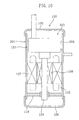
- the present embodiment is directed to a scroll compressor. In the first place, the entire arrangement of the scroll compressor of the first embodiment will be described with reference to Figure 1 .
- the scroll compressor (1) of the first embodiment is used to compress a low-level pressure refrigerant drawn in from the side of an evaporator and discharge it to the side of a condenser in a refrigerant circuit of an airconditioner or other device which performs a vapor compression refrigerating cycle.
- the scroll compressor (1) comprises a casing (10) housing therein a compression mechanism (20) and a compressor motor (30) which is a drive mechanism operable to activate the compression mechanism (20) .
- the compression mechanism (20) is disposed at an upper portion of the inside of the casing (10)
- the compressor motor (30) is disposed at a position slightly below the center of the inside of the casing (10) .
- the casing (10) is provided with a connector terminal (35) for supplying electric power to the compressor motor (30) .
- the casing (10) is made up of a trunk part (11) shaped like a cylinder and dish-shaped end plates (12, 13) secured firmly to an upper and lower ends of the trunk part (11) or to their vicinities respectively by welding.
- a suction pipe (14) is so disposed as to pass through the upper end plate (12) of the casing (10) .
- a discharge pipe (15) passing through the trunk part (11) is disposed at a position slightly above the center of the trunk part (11) so that it communicates with both the inside and the outside of the casing (10) . Additionally, it is arranged such that a given amount of lubricant (refrigerating machine oil) (not shown) is stored at the bottom of the casing (10) .
- the compressor motor (30) is made up of a stator (31) secured firmly to the trunk part (11) of the casing (10) and a rotor (32) disposed on the inner side of the stator (31) , and a drive shaft (33) is secured firmly to the rotor (32) of the motor (30) .
- the drive shaft (33) projects vertically relative to the stator (31) and the rotor (32) of the compressor motor (30) .
- An upper end of the drive shaft (33) is connected to the compression mechanism (20) , while a lower end thereof is rotatably supported on a bearing member (34) secured firmly to the lower end of the trunk part (11) of the casing (10).
- the compression mechanism (20) comprises a fixed scroll (21) , an orbiting scroll (22) , and a housing (23) .
- the fixed scroll (21) is made up of an end plate (21a) and an involute wrap (21b) formed in a lower surface of the end plate (21a) .
- the orbiting scroll (22) is made up of an end plate (22a) and an involute wrap (22b) formed in an upper surface of the end plate (22a) .
- the housing (23) constitutes a part of the compression mechanism (20) , and the position of the compression mechanism (20) is fixed by firmly securing the housing (23) to the casing (10) by press fitting.
- the housing (23) is a partition member dividing the internal space of the casing (10) into an upper space and a lower space. More specifically, a low-level pressure space is defined above the housing (23) and a high-level pressure space is defined below the housing (23) .
- the fixed scroll (21) is fastened firmly to an upper surface of the housing (23) by a fastening means such as a bolt (not shown).
- the orbiting scroll (22) is disposed between the fixed scroll (21) and the housing (23) .
- a rotation preventing member (24) such as an Oldham joint is disposed between the end plate (22a) of the orbiting scroll (22) and the housing (23) so that the orbiting scroll (22) executes only an orbital motion relative to the fixed scroll (21) .
- the wrap (21b) of the fixed scroll (21) and the wrap (22b) of the orbiting scroll (22) matingly engage with each other.
- a space between contacting parts of the wraps (21b, 22b) is formed as a compression chamber (25) .
- the compression chamber (25) is so structured as to compress refrigerant as the volume between the wraps (21b, 22b) shrinks toward the center with the revolution of the orbiting scroll (22) .
- a suction opening (21c) for low-level pressure refrigerant is formed at a peripheral edge of the compression chamber (25) .
- a discharge opening (22c) for high-level pressure refrigerant is formed centrally in the compression chamber (25) .
- the suction pipe (14) secured firmly to the end plate (12) of the casing (10) is connected to the refrigerant suction opening (21c) .
- Connected to the suction pipe (14) is an evaporator of the refrigerant circuit (not shown).
- a boss (22d) to which an upper end part (33a) of the drive shaft (33) is connected is formed centrally in the lower surface of the end plate (22a) of the orbiting scroll (22).
- its upper end part (33a) is an eccentric shaft portion deviating from the rotational center of the drive shaft (33) , and the drive shaft (33) is rotatably supported, at a position immediately below the eccentric shaft portion (33a) , on the housing ( 23) .
- a seal ring (26) disposed around the boss (22d) , engages with an inner aperture (23a) of the housing (23) , and it is arranged such that refrigerant gas at a high-level pressure introduced to the inner aperture (23a) will not leak to the outer peripheral side beyond the seal ring (26) .
- a discharge path (27) for guiding a high-level pressure refrigerant from the discharge opening (22c) of the orbiting scroll (22) to a space below the housing (23) , is formed in the drive shaft (33) .
- a lower end of the discharge path (27) opens at a position below the compressor motor (30) .
- the high-level pressure refrigerant gas flowing out of the discharge path (27) is supplied from the discharge pipe (15) disposed in the trunk part (11) of the casing (10) to a condenser of the refrigerant circuit through a refrigerant pipe (not shown).
- the drive shaft (33) is provided with a lubrication pump (28) and a lubrication path (33b) .
- the lubrication pump (28) is disposed at a lower end part of the drive shaft (33) and is so constructed as to draw lubricant (not shown) stored at the bottom of the casing (10) with the revolution of the drive shaft (33) .
- the lubrication path (33b) extends vertically in the inside of the drive shaft (33) and communicates with lubrication openings (not shown) formed at each part so that lubricant drawn by the lubrication pump (28) is supplied to each sliding part.
- the rotor (32) starts rotating when the motor (30) is activated, and, as a result, the drive shaft (33) rotates.
- the orbiting scroll (22) does not rotate on its axis but executes only an orbital motion relative to the fixed scroll (21) .
- low-level pressure refrigerant is sucked in to a peripheral edge part of the compressor chamber (25) from the suction pipe (14) .
- the refrigerant is compressed.
- the refrigerant which has now become high in pressure level, flows through the discharge path (27) and fills up a space below the housing (23) within the casing (10) .
- the refrigerant After being discharged from the discharge pipe (15) , the refrigerant is subjected to a condensation process, an expansion process, and an evaporation process in the refrigerant circuit and, thereafter, is again sucked in from the suction pipe (14) for compression, which is carried out repeatedly.
- the housing (23) vertically comparts the internal space of the casing (10) .
- the first embodiment is characterized in that the housing (23) itself has a function of providing sealing between the low-level pressure space above the housing (23) and the high-level pressure space below the housing (23) . Referring to Figures 2 and 3 , such a seal construction will be described below.
- FIG. 2 which is an enlarged cross-sectional view of the seal construction, shows that the housing (23) is dimension-structured such that an outer peripheral surface (40) of the housing (23) is secured firmly to the trunk part (11) of the casing (10) by press fitting.
- a collar part (41) which projects radially outwardly so as to abut against an upper end surface of the trunk part (11) .
- a peripheral groove (42) formed in the outer peripheral surface (40) of the housing (23) is a peripheral groove (42) extending continuously in a circumferential direction for allowing for shrinkage of the casing (10) caused by welding at a weld area where the trunk part (11) and the end plate (12) are welded together.
- the peripheral groove (42) is formed at a position immediately below the collar part (41) in the outer peripheral surface (40) of the housing (23) .
- the housing (23) has a thick and thin parts (43) and (44) of different thicknesses relative to a radial direction.
- the thick part (43) is a thick part whose radial dimension is constant throughout.
- the thin part (44) is a part which partially includes at least a thin subpart.
- the outer peripheral surface (40) of the housing (23) is provided, at a position in dose proximity to the lower end of the peripheral groove (42) , with a projection part (45) continuously extending in a circumferential direction, and the projection part (45) is located on the outer periphery of the thick part (43) .
- the projection part (45) is so formed as to be press-fitted to the trunk part (11) of the casing (10) , and, as shown in Figure 3 which is an enlarged view of the projection part (45) , its axial (upper and lower) ends (45a, 45b) are each formed into a tapered surface.
- the tapered surface (45a) on the press-fitting side (lower side) relative to the trunk part inclines at an angle of about 15 degrees with respect to the outer peripheral surface (40) of the housing (23) .
- the tapered surface (45b) on the side (upper side) opposite to the press-fitting side inclines at an angle of about 45 degrees with respect to the outer peripheral surface (40) of the housing (23) .
- the upper end plate (12) of the casing (10) is such formed that it abuts against the housing (23) in an axial direction and is clearance-fitted to the trunk part (11) and the housing (23) in a radial direction.
- the position of the end plate (12) is located axially with respect to the trunk part (11) and the housing (23) , but is not located radially at this portion. Because of this, assembling work during welding of the trunk part (11) and the end plate (12) becomes easy to perform.
- the housing (23) of the compression mechanism (20) is press-fitted to the trunk part (11) until the collar part (41) comes into abutment against the upper end surface of the trunk part (11) , and, thereafter, the end plate (12) is welded to the trunk part (11) , whereby the compression mechanism (20) is located securely within the casing (10) and the high-level pressure space and the low-level pressure space are sealed off from each other.
- the housing (23) is press-fitted to the trunk part (11) , as shown in Figure 2(a) .
- the outer peripheral surface (40) of the housing (23) comes into press contact with the inner peripheral surface of the trunk part (11) and the projection part (45) cuts into the inner peripheral surface of the trunk part (11) .
- the end plate (12) is welded to the trunk part (11)
- the trunk part (11) shrinks at the position of the peripheral groove (42) after welding (after cooling), and the trunk part (11) strongly tightens the housing (23) in a region at least from the peripheral groove (42) to the area immediately therebelow.
- the present embodiment provides the same sealability as thermal insert does. In the present embodiment, however, thermal insert is practically unnecessary. Moreover, since sealability is enhanced by making utilization of welding of the trunk part (11) and the end plate (12) which is an operation to be done inevitably for the compressor (1) of such a type, this eliminates the need for performing any other additional operations for seal function, and workability at assembling time is at the same level as when only press-fitting is carried out, and is excellently good.
- the first embodiment eliminates the need for the provision of a component part dedicated for sealing such as an O-ring. Therefore, the number of component parts for seal function will not increase and, therefore, the increase in costs will not occur.
- the projection part (45) on the forward side relative to the direction of press-fitting to the trunk part (11) is formed into the tapered surface (45a) , this facilitates press-fitting of the housing (23) to the casing (10) .
- the other end of the projection part (45) on the rearward side relative to the press-fitting direction is formed into the tapered surface (45b) and, as a result of such arrangement, when the trunk part (11) shrinks along the tapered surface (45b) at a weld area where the trunk part (11) and the end plate (12) are welded together, such a shrinking area comes into press contact with the tapered surface (45a) , thereby making it possible to provide sufficient sealability.
- insufficient press-contacting of this part with the tapered surface (45a) may cause a decrease in sealability.
- the shrinking area is brought into sufficient press contact with the tapered surface (45a) thereby improving sealability.
- the projection part (45) is formed on the outer periphery of the thick part (43) of the housing (23) and, as a result of such arrangement, it becomes possible for the thick part (43) to sufficiently resist forces strongly tightening the housing (23) produced when the casing (10) shrinks by welding. Accordingly, even when the casing (10) shrinks, the housing (23) will undergo no deformation.
- the housing (23) to which the fixed scroll (21) is firmly secured is press-fitted to the trunk part (11) ;
- the projection part (45) is formed in the outer peripheral surface (40) of the housing (23) ;
- the housing (23) is tightened by the trunk part (11) so that the high-level pressure space and the low-level pressure space are sealed off from each other, whereby tightening forces produced when the casing (10) shrinks will not act directly on the fixed scroll (21) . Consequently, the wrap (21b) of the fixed scroll ( 21) will not deform and the decrement in performance of the compressor (1) due to refrigerant leakage or the like will not take place.
- the casing (10) is such constructed that the end plate (12) is engaged by clearance fitting with the trunk part (11) and the outer periphery of the housing (23) .
- the end plate (12) may be formed so as to fit into the inner peripheral side of the trunk part (11) of the casing (10) , and the peripheral groove (42) of the housing (23) may be formed such that it enables the end plate (12) to shrink by welding, as shown in Figure 4 .
- the peripheral groove (42) of the housing (23) may receive any one of the trunk part (11) and the end plate (12) as long as the casing (10) is constructed so as to strongly tighten the housing (23) by allowing the casing (10) to shrink at a weld area where the trunk part (11) and the end plate (12) are welded together. Also in the arrangement described above, it is possible to provide the same effects as does the first embodiment.
- the second modification example is a modification example of the projection part.
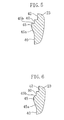
- Figure 7 illustrates an example in which neither the upper end part (45b) nor the lower end part (45a) of the projection part (45) is formed into a tapered surface.
- the upper end part (45b) and the lower end part (45a) are end surfaces which rise perpendicularly from the outer peripheral surface (40) of the housing (23) .
- the casing (10) strongly tightens the projection part (45) when the casing (10) shrinks after the trunk part (11) and the end plate (12) are welded together, thereby enhancing sealability more than conventional, substantially as in the above. In addition, it is possible to prevent the decrease in workability.
- Figure 8 shows an example in which the projection part (46, 47) is provided at a plurality of areas of the outer peripheral surface (40) of the housing (23) .
- the projection parts (46, 47) differ in projection height from each other. More specifically, the projection height of the projection part (46) on the press-fitting side (lower side) of the housing (23) to the trunk part (11) is made smaller, and the projection height of the projection part (47) on the rearward side (upper side) thereof is made greater.
- the projection parts (46, 47) which extend continuously in a circumferential direction in the outer peripheral surface (40) of the housing (23) are arranged in multiple in the axial direction of the housing (23) .
- the number of press-fitting points of the projection parts (46, 47) to the trunk part (11) increases thereby providing enhanced sealability.
- the projection height of the projection part (46) on the press-fitting side of the housing (23) with respect to the trunk part (11) is made shorter, this makes it possible to press-fit the housing (23) to the casing (10) with relative ease while securing excellent sealability.
- the outer peripheral surface (40) of the housing (23) is press-fitted to the trunk part (11) and, thereafter, the peripheral groove (42) and the projection part (45)(46, 47) are formed in the outer peripheral surface (40) .
- the outer peripheral surface (40) of the housing (23) is clearance-fitted to the trunk part (11) of the casing (10), as shown in Figure 9 . It should be noted that the Figure illustrates such clearance-fitting in an exaggerated manner.
- the second embodiment is the same as the first embodiment in the following points. That is to say, the peripheral groove (42) which continuously extends in a circumferential direction so as to allow for shrinkage of the casing (10) due to welding at a weld area where the trunk part (11) and the end plate (12) are welded together and the projection part (45) which continuously extends in a circumferential direction at a position in close proximity to the peripheral groove (42) are formed in the outer peripheral surface (40) of the housing (23) , and the projection part (45) is so formed as to be press-fitted to the trunk part (11) of the casing (10) . Further, other arrangements are the same as the first embodiment.
- trunk part (11) and the end plate (12) are welded together, with the projection part (45) of the housing (23) press-fitted to the trunk part (11) , thereby causing the casing (10) to shrink at the position of the peripheral groove (42) .
- the tightening force of the casing (10) increases. Accordingly, also in this arrangement it is possible to provide sealability of the same level that thermal insert does.
- the housing (23) is clearance-fitted to the casing (10) , as a result of which the casing (10) strongly tightens only the projection part (45) and strong tightening forces will not act on the whole of the housing (23) . Consequently, the housing (23) is unlikely to undergo deformation or the like.
- the projection part (45)(46, 47) may be modified as shown in Figures 5-8 .
- the housing (23) serves as a partition member
- the fixed scroll (21) is attached firmly, as a partition member, to the casing (10) to define a high-level pressure space and a low-level pressure space.
- a projection part is formed around a thick part (for example, the end plate (12) ) of the fixed scroll (21) . This avoids strong forces from acting on the wrap (21b) . This avoids not only refrigerant leakage due to the deformation of the wrap (21b) but also performance decrement.
- the present invention is applicable to rotating compressors of the other type such as rotary compressors and swing compressors.
- a partition member for dividing the inside of the casing (10) into a high-level pressure space and a low-level pressure space is press-fitted to the casing (10) at a weld area where the trunk part (11) and the end plate (12) are welded together and the partition member is tightened strongly by making utilization of shrinkage of the casing (10) caused by welding.
- the projection part (45)(46, 47) is not necessarily formed.
- the housing (23) having, at the outer peripheral surface (40) , no projection part is press-fitted to the trunk part (11) and tightening force resulting from post-welding shrinkage is utilized.
- assembling work is easy to carry out and, besides, the casing (10) strongly tightens the outer peripheral surface of the housing (23) because of its shrinkage caused by welding, thereby making it possible to further enhance sealability than conventional.
- the arrangement in which the housing (23) is press-fitted to the trunk part (11) of the casing (10) for firm attachment thereto has been descried.
- a partition member such as the housing (23) is secured firmly to the end plate (12) of the casing (10) .
- the present invention is useful for rotating compressors.
Landscapes
- Engineering & Computer Science (AREA)
- Mechanical Engineering (AREA)
- General Engineering & Computer Science (AREA)
- Applications Or Details Of Rotary Compressors (AREA)
- Rotary Pumps (AREA)
- Compressor (AREA)
Abstract
Description
Claims (9)
- A rotating compressor comprising a casing (10) housing therein: a compressor motor (30), a compression mechanism (20) which is driven by said compressor motor (30), and a partition member (23) which divides the inside of said casing (10) into a high-level pressure space and a low-level pressure space, said casing (10) having a trunk part (11) shaped like a cylinder and an end plate (12) secured firmly to said trunk part (11) by welding,
wherein:said partition member (23) is so formed as to be press-fitted to said casing (10) at a weld area where said trunk part (11) and said end plate (12) are welded together or in the vicinity of said weld area; anda peripheral groove (42) extending continuously in a circumferential direction for allowing for shrinkage of said casing (10) caused by welding at said weld area of said trunk part (11) and said end plate (12) is formed in an outer peripheral surface (40) of said partition member (23). - The rotating compressor of claim 1,
wherein:a projection part (45)(46, 47) extending continuously in a circumferential direction at a position in proximity to said peripheral groove (42) is formed in said outer peripheral surface (40) of said partition member (23), andsaid projection part (45)(46, 47) is so formed as to be press-fitted to said casing (10). - A rotating compressor comprising a casing (10) housing therein: a compressor motor (30), a compression mechanism (20) which is driven by said compressor motor (30), and a partition member (23) which divides the inside of said casing (10) into a high-level pressure space and a low-level pressure space, said casing (10) having a trunk part (11) shaped like a cylinder and an end plate (12) secured firmly to said trunk part (11) by welding,
wherein:said partition member (23) is so formed as to be clearance-fitted to said casing (10) at a weld area where said trunk part (11) and said end plate (12) are welded together or in the vicinity of said weld area,a peripheral groove (42) extending continuously in a circumferential direction for allowing for shrinkage of said casing (10) caused by welding at said weld area of said trunk part (11) and said end plate (12), and a projection part (45)(46, 47) extending continuously in a circumferential direction at a position in proximity to said peripheral groove (42) are formed in an outer peripheral surface (40) of said partition member (23), andsaid projection part (45)(46, 47) is so formed as to be press-fitted to said casing (10). - The rotating compressor of either claim 2 or claim 3, wherein said projection part (46, 47) of said partition member (23) is provided at a plurality of areas.
- The rotating compressor of claim 4, wherein said projection parts (46, 47) differ in projection height from each other.
- The rotating compressor of either claim 2 or claim 3, wherein one end or both ends (45a, 45b) of said projection part (45)(46, 47) relative to the axial direction of said partition member (23) are formed into a tapered surface.
- The rotating compressor of either claim 2 or claim 3,
wherein:said partition member (23) has a thick and thin parts (43) and (44) of different thicknesses relative to a radial direction, andsaid projection part (45)(46, 47) is formed on an outer periphery of said thick part (43). - The rotating compressor of any one of claims 1-3, wherein said end plate (12) of said casing (10) comes into axial abutment against said trunk part (11) or said partition member (23) and is so formed as to be clearance-fitted to said trunk part (11) or said partition member (23).
- The rotating compressor of any one of claims 1-3,
wherein:said compression mechanism (20) is composed of a scroll type compression mechanism (20), andsaid partition member (23) is such formed that a fixed scroll (21) is secured firmly to said partition member (23).
Applications Claiming Priority (3)
| Application Number | Priority Date | Filing Date | Title |
|---|---|---|---|
| JP2002094199A JP3788380B2 (en) | 2002-03-29 | 2002-03-29 | Rotary compressor |
| JP2002094199 | 2002-03-29 | ||
| PCT/JP2003/002282 WO2003083308A1 (en) | 2002-03-29 | 2003-02-27 | Rotary compressor |
Publications (3)
| Publication Number | Publication Date |
|---|---|
| EP1496262A1 true EP1496262A1 (en) | 2005-01-12 |
| EP1496262A4 EP1496262A4 (en) | 2009-07-29 |
| EP1496262B1 EP1496262B1 (en) | 2015-11-04 |
Family
ID=28671781
Family Applications (1)
| Application Number | Title | Priority Date | Filing Date |
|---|---|---|---|
| EP03707161.0A Expired - Lifetime EP1496262B1 (en) | 2002-03-29 | 2003-02-27 | Rotary compressor |
Country Status (10)
| Country | Link |
|---|---|
| EP (1) | EP1496262B1 (en) |
| JP (1) | JP3788380B2 (en) |
| KR (1) | KR100549613B1 (en) |
| CN (1) | CN1274961C (en) |
| AU (1) | AU2003211203B2 (en) |
| BR (1) | BR0301921B1 (en) |
| ES (1) | ES2553984T3 (en) |
| MY (1) | MY128662A (en) |
| TW (1) | TW593892B (en) |
| WO (1) | WO2003083308A1 (en) |
Families Citing this family (5)
| Publication number | Priority date | Publication date | Assignee | Title |
|---|---|---|---|---|
| CN103375389B (en) * | 2012-04-30 | 2017-01-18 | 艾默生环境优化技术有限公司 | Compressor staking arrangement and method |
| US9964122B2 (en) | 2012-04-30 | 2018-05-08 | Emerson Climate Technologies, Inc. | Compressor staking arrangement and method |
| JP6467324B2 (en) * | 2015-09-29 | 2019-02-13 | 株式会社神戸製鋼所 | Screw compressor |
| JP7071670B2 (en) * | 2020-08-25 | 2022-05-19 | ダイキン工業株式会社 | Compressor and manufacturing method of compressor |
| EP4303442B1 (en) * | 2021-03-01 | 2025-08-27 | Daikin Industries, Ltd. | Compressor and refrigeration cycle device |
Family Cites Families (6)
| Publication number | Priority date | Publication date | Assignee | Title |
|---|---|---|---|---|
| DE3215394A1 (en) | 1982-04-24 | 1983-11-03 | Goetze Ag, 5093 Burscheid | MACHINE FOR CIRCUMFERENTIAL MACHINING |
| JP3403783B2 (en) * | 1993-12-10 | 2003-05-06 | 東芝キヤリア株式会社 | Hermetic compressor |
| JPH0932771A (en) * | 1995-07-25 | 1997-02-04 | Mitsubishi Electric Corp | Scroll compressor |
| JPH09256970A (en) | 1996-03-25 | 1997-09-30 | Mitsubishi Electric Corp | Scroll compressor |
| JPH1122682A (en) * | 1997-07-03 | 1999-01-26 | Daikin Ind Ltd | Seal structure in casing |
| JP2000097183A (en) | 1998-09-18 | 2000-04-04 | Daikin Ind Ltd | Rotary compressor |
-
2002
- 2002-03-29 JP JP2002094199A patent/JP3788380B2/en not_active Expired - Lifetime
-
2003
- 2003-02-27 EP EP03707161.0A patent/EP1496262B1/en not_active Expired - Lifetime
- 2003-02-27 BR BRPI0301921-7A patent/BR0301921B1/en not_active IP Right Cessation
- 2003-02-27 AU AU2003211203A patent/AU2003211203B2/en not_active Ceased
- 2003-02-27 WO PCT/JP2003/002282 patent/WO2003083308A1/en not_active Ceased
- 2003-02-27 ES ES03707161.0T patent/ES2553984T3/en not_active Expired - Lifetime
- 2003-02-27 KR KR1020037015762A patent/KR100549613B1/en not_active Expired - Fee Related
- 2003-02-27 CN CNB038002515A patent/CN1274961C/en not_active Expired - Fee Related
- 2003-03-26 MY MYPI20031093A patent/MY128662A/en unknown
- 2003-03-28 TW TW092107117A patent/TW593892B/en not_active IP Right Cessation
Also Published As
| Publication number | Publication date |
|---|---|
| ES2553984T3 (en) | 2015-12-15 |
| CN1509379A (en) | 2004-06-30 |
| KR100549613B1 (en) | 2006-02-03 |
| EP1496262A4 (en) | 2009-07-29 |
| CN1274961C (en) | 2006-09-13 |
| KR20040004680A (en) | 2004-01-13 |
| TW200402508A (en) | 2004-02-16 |
| AU2003211203B2 (en) | 2005-07-07 |
| MY128662A (en) | 2007-02-28 |
| JP3788380B2 (en) | 2006-06-21 |
| EP1496262B1 (en) | 2015-11-04 |
| JP2003293975A (en) | 2003-10-15 |
| AU2003211203A1 (en) | 2003-10-13 |
| BR0301921B1 (en) | 2013-03-19 |
| TW593892B (en) | 2004-06-21 |
| BR0301921A (en) | 2004-02-25 |
| WO2003083308A1 (en) | 2003-10-09 |
Similar Documents
| Publication | Publication Date | Title |
|---|---|---|
| US6884046B2 (en) | Scroll compressor | |
| US6439867B1 (en) | Scroll compressor having a clearance for the oldham coupling | |
| US7607904B2 (en) | Rotary compressor with low pressure space surrounding outer peripheral face of compression mechanism and discharge passage passing through housing | |
| EP3567253A1 (en) | Compressor having enhanced wrap structure | |
| US20040096338A1 (en) | Assembling mechanism of discharge pipe for hermetic compressor and method thereof | |
| EP1496262B1 (en) | Rotary compressor | |
| JP3858762B2 (en) | Slide bush and scroll type fluid machine | |
| JPH08165994A (en) | Scroll type fluid device | |
| JP7329774B2 (en) | scroll compressor | |
| KR102321486B1 (en) | Scroll compressor and manufacturing method for the same | |
| JP2770630B2 (en) | Scroll compressor | |
| CN101072950A (en) | Rotary compressor | |
| CN223411013U (en) | Scroll compressor | |
| JPH07310682A (en) | Scroll type fluid machine | |
| JP2005061304A (en) | Scroll type fluid machine | |
| JP2001153068A (en) | Scroll compressor | |
| KR20190004200A (en) | Compressor having enhanced structure for preventing refrigerant leakage | |
| KR100664048B1 (en) | High and low pressure separation structure of scroll compressor | |
| JPH11159480A (en) | Scroll compressor | |
| JP2005113792A (en) | Hermetic compressor | |
| JPH08177757A (en) | Hermetic scroll compressor | |
| JPH08144979A (en) | Hermetic scroll compressor | |
| JP6425487B2 (en) | Scroll type fluid machine | |
| JPH01237375A (en) | scroll compressor | |
| JPH0636310Y2 (en) | Scroll compressor |
Legal Events
| Date | Code | Title | Description |
|---|---|---|---|
| PUAI | Public reference made under article 153(3) epc to a published international application that has entered the european phase |
Free format text: ORIGINAL CODE: 0009012 |
|
| 17P | Request for examination filed |
Effective date: 20030703 |
|
| AK | Designated contracting states |
Kind code of ref document: A1 Designated state(s): AT BE BG CH CY CZ DE DK EE ES FI FR GB GR HU IE IT LI LU MC NL PT SE SI SK TR |
|
| A4 | Supplementary search report drawn up and despatched |
Effective date: 20090626 |
|
| 17Q | First examination report despatched |
Effective date: 20091006 |
|
| GRAP | Despatch of communication of intention to grant a patent |
Free format text: ORIGINAL CODE: EPIDOSNIGR1 |
|
| INTG | Intention to grant announced |
Effective date: 20150601 |
|
| GRAS | Grant fee paid |
Free format text: ORIGINAL CODE: EPIDOSNIGR3 |
|
| GRAA | (expected) grant |
Free format text: ORIGINAL CODE: 0009210 |
|
| AK | Designated contracting states |
Kind code of ref document: B1 Designated state(s): AT BE BG CH CY CZ DE DK EE ES FI FR GB GR HU IE IT LI LU MC NL PT SE SI SK TR |
|
| REG | Reference to a national code |
Ref country code: GB Ref legal event code: FG4D |
|
| REG | Reference to a national code |
Ref country code: CH Ref legal event code: EP |
|
| REG | Reference to a national code |
Ref country code: AT Ref legal event code: REF Ref document number: 759400 Country of ref document: AT Kind code of ref document: T Effective date: 20151115 |
|
| REG | Reference to a national code |
Ref country code: IE Ref legal event code: FG4D |
|
| REG | Reference to a national code |
Ref country code: DE Ref legal event code: R096 Ref document number: 60348209 Country of ref document: DE |
|
| REG | Reference to a national code |
Ref country code: ES Ref legal event code: FG2A Ref document number: 2553984 Country of ref document: ES Kind code of ref document: T3 Effective date: 20151215 |
|
| REG | Reference to a national code |
Ref country code: FR Ref legal event code: PLFP Year of fee payment: 14 |
|
| REG | Reference to a national code |
Ref country code: NL Ref legal event code: MP Effective date: 20151104 |
|
| REG | Reference to a national code |
Ref country code: AT Ref legal event code: MK05 Ref document number: 759400 Country of ref document: AT Kind code of ref document: T Effective date: 20151104 |
|
| PG25 | Lapsed in a contracting state [announced via postgrant information from national office to epo] |
Ref country code: NL Free format text: LAPSE BECAUSE OF FAILURE TO SUBMIT A TRANSLATION OF THE DESCRIPTION OR TO PAY THE FEE WITHIN THE PRESCRIBED TIME-LIMIT Effective date: 20151104 |
|
| PG25 | Lapsed in a contracting state [announced via postgrant information from national office to epo] |
Ref country code: AT Free format text: LAPSE BECAUSE OF FAILURE TO SUBMIT A TRANSLATION OF THE DESCRIPTION OR TO PAY THE FEE WITHIN THE PRESCRIBED TIME-LIMIT Effective date: 20151104 Ref country code: GR Free format text: LAPSE BECAUSE OF FAILURE TO SUBMIT A TRANSLATION OF THE DESCRIPTION OR TO PAY THE FEE WITHIN THE PRESCRIBED TIME-LIMIT Effective date: 20160205 Ref country code: PT Free format text: LAPSE BECAUSE OF FAILURE TO SUBMIT A TRANSLATION OF THE DESCRIPTION OR TO PAY THE FEE WITHIN THE PRESCRIBED TIME-LIMIT Effective date: 20160304 Ref country code: SE Free format text: LAPSE BECAUSE OF FAILURE TO SUBMIT A TRANSLATION OF THE DESCRIPTION OR TO PAY THE FEE WITHIN THE PRESCRIBED TIME-LIMIT Effective date: 20151104 Ref country code: FI Free format text: LAPSE BECAUSE OF FAILURE TO SUBMIT A TRANSLATION OF THE DESCRIPTION OR TO PAY THE FEE WITHIN THE PRESCRIBED TIME-LIMIT Effective date: 20151104 |
|
| PG25 | Lapsed in a contracting state [announced via postgrant information from national office to epo] |
Ref country code: CZ Free format text: LAPSE BECAUSE OF FAILURE TO SUBMIT A TRANSLATION OF THE DESCRIPTION OR TO PAY THE FEE WITHIN THE PRESCRIBED TIME-LIMIT Effective date: 20151104 |
|
| REG | Reference to a national code |
Ref country code: DE Ref legal event code: R097 Ref document number: 60348209 Country of ref document: DE |
|
| PG25 | Lapsed in a contracting state [announced via postgrant information from national office to epo] |
Ref country code: EE Free format text: LAPSE BECAUSE OF FAILURE TO SUBMIT A TRANSLATION OF THE DESCRIPTION OR TO PAY THE FEE WITHIN THE PRESCRIBED TIME-LIMIT Effective date: 20151104 Ref country code: SK Free format text: LAPSE BECAUSE OF FAILURE TO SUBMIT A TRANSLATION OF THE DESCRIPTION OR TO PAY THE FEE WITHIN THE PRESCRIBED TIME-LIMIT Effective date: 20151104 Ref country code: DK Free format text: LAPSE BECAUSE OF FAILURE TO SUBMIT A TRANSLATION OF THE DESCRIPTION OR TO PAY THE FEE WITHIN THE PRESCRIBED TIME-LIMIT Effective date: 20151104 |
|
| PLBE | No opposition filed within time limit |
Free format text: ORIGINAL CODE: 0009261 |
|
| STAA | Information on the status of an ep patent application or granted ep patent |
Free format text: STATUS: NO OPPOSITION FILED WITHIN TIME LIMIT |
|
| PG25 | Lapsed in a contracting state [announced via postgrant information from national office to epo] |
Ref country code: LU Free format text: LAPSE BECAUSE OF FAILURE TO SUBMIT A TRANSLATION OF THE DESCRIPTION OR TO PAY THE FEE WITHIN THE PRESCRIBED TIME-LIMIT Effective date: 20160227 Ref country code: MC Free format text: LAPSE BECAUSE OF FAILURE TO SUBMIT A TRANSLATION OF THE DESCRIPTION OR TO PAY THE FEE WITHIN THE PRESCRIBED TIME-LIMIT Effective date: 20151104 |
|
| REG | Reference to a national code |
Ref country code: CH Ref legal event code: PL |
|
| 26N | No opposition filed |
Effective date: 20160805 |
|
| PG25 | Lapsed in a contracting state [announced via postgrant information from national office to epo] |
Ref country code: LI Free format text: LAPSE BECAUSE OF NON-PAYMENT OF DUE FEES Effective date: 20160229 Ref country code: CH Free format text: LAPSE BECAUSE OF NON-PAYMENT OF DUE FEES Effective date: 20160229 |
|
| PG25 | Lapsed in a contracting state [announced via postgrant information from national office to epo] |
Ref country code: SI Free format text: LAPSE BECAUSE OF FAILURE TO SUBMIT A TRANSLATION OF THE DESCRIPTION OR TO PAY THE FEE WITHIN THE PRESCRIBED TIME-LIMIT Effective date: 20151104 |
|
| REG | Reference to a national code |
Ref country code: IE Ref legal event code: MM4A |
|
| REG | Reference to a national code |
Ref country code: FR Ref legal event code: PLFP Year of fee payment: 15 |
|
| PG25 | Lapsed in a contracting state [announced via postgrant information from national office to epo] |
Ref country code: IE Free format text: LAPSE BECAUSE OF NON-PAYMENT OF DUE FEES Effective date: 20160227 |
|
| REG | Reference to a national code |
Ref country code: FR Ref legal event code: PLFP Year of fee payment: 16 |
|
| PG25 | Lapsed in a contracting state [announced via postgrant information from national office to epo] |
Ref country code: CY Free format text: LAPSE BECAUSE OF FAILURE TO SUBMIT A TRANSLATION OF THE DESCRIPTION OR TO PAY THE FEE WITHIN THE PRESCRIBED TIME-LIMIT Effective date: 20151104 Ref country code: HU Free format text: LAPSE BECAUSE OF FAILURE TO SUBMIT A TRANSLATION OF THE DESCRIPTION OR TO PAY THE FEE WITHIN THE PRESCRIBED TIME-LIMIT; INVALID AB INITIO Effective date: 20030227 |
|
| PG25 | Lapsed in a contracting state [announced via postgrant information from national office to epo] |
Ref country code: TR Free format text: LAPSE BECAUSE OF FAILURE TO SUBMIT A TRANSLATION OF THE DESCRIPTION OR TO PAY THE FEE WITHIN THE PRESCRIBED TIME-LIMIT Effective date: 20151104 |
|
| PG25 | Lapsed in a contracting state [announced via postgrant information from national office to epo] |
Ref country code: BG Free format text: LAPSE BECAUSE OF FAILURE TO SUBMIT A TRANSLATION OF THE DESCRIPTION OR TO PAY THE FEE WITHIN THE PRESCRIBED TIME-LIMIT Effective date: 20151104 |
|
| PGFP | Annual fee paid to national office [announced via postgrant information from national office to epo] |
Ref country code: GB Payment date: 20190227 Year of fee payment: 17 |
|
| PGFP | Annual fee paid to national office [announced via postgrant information from national office to epo] |
Ref country code: BE Payment date: 20190116 Year of fee payment: 17 |
|
| GBPC | Gb: european patent ceased through non-payment of renewal fee |
Effective date: 20200227 |
|
| REG | Reference to a national code |
Ref country code: BE Ref legal event code: MM Effective date: 20200229 |
|
| PG25 | Lapsed in a contracting state [announced via postgrant information from national office to epo] |
Ref country code: GB Free format text: LAPSE BECAUSE OF NON-PAYMENT OF DUE FEES Effective date: 20200227 |
|
| PG25 | Lapsed in a contracting state [announced via postgrant information from national office to epo] |
Ref country code: BE Free format text: LAPSE BECAUSE OF NON-PAYMENT OF DUE FEES Effective date: 20200229 |
|
| PGFP | Annual fee paid to national office [announced via postgrant information from national office to epo] |
Ref country code: ES Payment date: 20210308 Year of fee payment: 19 |
|
| PGFP | Annual fee paid to national office [announced via postgrant information from national office to epo] |
Ref country code: DE Payment date: 20220105 Year of fee payment: 20 |
|
| PGFP | Annual fee paid to national office [announced via postgrant information from national office to epo] |
Ref country code: IT Payment date: 20220111 Year of fee payment: 20 Ref country code: FR Payment date: 20220118 Year of fee payment: 20 |
|
| REG | Reference to a national code |
Ref country code: DE Ref legal event code: R071 Ref document number: 60348209 Country of ref document: DE |
|
| REG | Reference to a national code |
Ref country code: ES Ref legal event code: FD2A Effective date: 20230331 |
|
| PG25 | Lapsed in a contracting state [announced via postgrant information from national office to epo] |
Ref country code: ES Free format text: LAPSE BECAUSE OF NON-PAYMENT OF DUE FEES Effective date: 20220228 |