EP1496218A2 - Lower link of piston crank mechanism for internal combustion engine - Google Patents
Lower link of piston crank mechanism for internal combustion engine Download PDFInfo
- Publication number
- EP1496218A2 EP1496218A2 EP04015253A EP04015253A EP1496218A2 EP 1496218 A2 EP1496218 A2 EP 1496218A2 EP 04015253 A EP04015253 A EP 04015253A EP 04015253 A EP04015253 A EP 04015253A EP 1496218 A2 EP1496218 A2 EP 1496218A2
- Authority
- EP
- European Patent Office
- Prior art keywords
- pin
- lower link
- link
- pin receiving
- contour
- Prior art date
- Legal status (The legal status is an assumption and is not a legal conclusion. Google has not performed a legal analysis and makes no representation as to the accuracy of the status listed.)
- Granted
Links
- 230000007246 mechanism Effects 0.000 title claims abstract description 21
- 238000002485 combustion reaction Methods 0.000 title claims description 12
- 230000013011 mating Effects 0.000 description 4
- 230000008901 benefit Effects 0.000 description 3
- 238000010276 construction Methods 0.000 description 2
- 238000010008 shearing Methods 0.000 description 2
- 230000005540 biological transmission Effects 0.000 description 1
- 230000005484 gravity Effects 0.000 description 1
- 230000004048 modification Effects 0.000 description 1
- 238000012986 modification Methods 0.000 description 1
- 230000009467 reduction Effects 0.000 description 1
- 230000003014 reinforcing effect Effects 0.000 description 1
- 238000007493 shaping process Methods 0.000 description 1
Images


Classifications
-
- F—MECHANICAL ENGINEERING; LIGHTING; HEATING; WEAPONS; BLASTING
- F02—COMBUSTION ENGINES; HOT-GAS OR COMBUSTION-PRODUCT ENGINE PLANTS
- F02B—INTERNAL-COMBUSTION PISTON ENGINES; COMBUSTION ENGINES IN GENERAL
- F02B75/00—Other engines
- F02B75/04—Engines with variable distances between pistons at top dead-centre positions and cylinder heads
- F02B75/048—Engines with variable distances between pistons at top dead-centre positions and cylinder heads by means of a variable crank stroke length
-
- F—MECHANICAL ENGINEERING; LIGHTING; HEATING; WEAPONS; BLASTING
- F02—COMBUSTION ENGINES; HOT-GAS OR COMBUSTION-PRODUCT ENGINE PLANTS
- F02B—INTERNAL-COMBUSTION PISTON ENGINES; COMBUSTION ENGINES IN GENERAL
- F02B75/00—Other engines
- F02B75/04—Engines with variable distances between pistons at top dead-centre positions and cylinder heads
- F02B75/045—Engines with variable distances between pistons at top dead-centre positions and cylinder heads by means of a variable connecting rod length
Definitions
- the present invention relates in general to piston crank mechanisms for a reciprocating type internal combustion engine, and more particularly to a lower link of the piston crank mechanisms of a double link type.
- a control link is further employed which has one end pivotally connected to a fixed portion of an associated engine and the other end pivotally connected to the lower link.
- a control link is pivotally connected to an upper link, not to a lower link. That is, the mechanism comprises an upper link pivotally connected to a piston through a piston pin, a lower link pivotally disposed on a crank pin of a crankshaft and pivotally connected to the upper link, and a control link having one end pivotally connected to a fixed portion of an associated engine and the other end pivotally connected to the upper link.
- the lower link of the double link type piston crank mechanisms functions to transmit a piston power produced as a result of a combustion in a cylinder to the crankshaft with the aid of the upper link and the control link.
- a high mechanical strength is needed by the lower link for standing the transmission of such piston power.
- the mechanical strength can be increased when the lower link has a bulky and thicker structure.
- the weight of the lower link is increased ironically, which exerts an undesired influence on a smoothed operation of the piston crank mechanism. Hitherto, various attempts have been carried out for overcoming such antinomical matter.
- a lower link for use in a piston crank mechanism of an internal combustion engine, the piston crank mechanism including an upper link that has one end pivotally connected to a piston through a piston pin, the lower link that is of a split type including upper and lower half-parts coupled by a bolt and is pivotally connected to the other end of the upper link through an upper pin and pivotally disposed on a crank pin of a crankshaft and a control link that has one end pivotally connected to a fixed portion of the engine and the other end pivotally connected to the lower link through a control pin.
- the lower link comprises a crank pin bearing housing portion adapted to receive the crank pin, the crank pin bearing housing portion defining a first contour; an upper pin receiving bore portion adapted to receive the upper pin, the upper pin receiving bore portion defining a second contour; a control pin receiving bore portion adapted to receive the control pin, the control pin receiving bore portion defining a third contour; a given portion that has therein an internally threaded bore formed in one of the upper and lower half-parts of the lower link and a bored portion formed in the other of the upper and lower half-parts of the lower link, the given portion defining a fourth contour, the upper and lower half-parts being coupled by the bolt that passes through the bored portion and is engaged with the internally threaded bore; and radially projected portions that extend radially outward beyond an imaginary minimum reference contour that is provided by connecting outer edge portions of the first, second, third and fourth contours with a continuous line.
- a lower link for use in a piston crank mechanism of an internal combustion engine, the piston crank mechanism including an upper link that has one end pivotally connected to a piston through a piston pin, the lower link that is of a split type including upper and lower half-parts coupled by a bolt and is pivotally connected to the other end of the upper link through an upper pin and pivotally disposed on a crank pin of a crankshaft and a control link that has one end pivotally connected to a fixed portion of the engine and the other end pivotally connected to the lower link through a control pin.
- the lower link comprises a crank pin bearing housing portion adapted to receive the crank pin, the crank pin bearing housing portion defining a first contour; an upper pin receiving bore portion adapted to receive the upper pin, the upper pin receiving bore portion defining a second contour; a control pin receiving bore portion adapted to receive the control pin, the control pin receiving bore portion defining a third contour; a given portion that has therein an internally threaded bore formed in one of the upper and lower half-parts of the lower link and a bored portion formed in the other of the upper and lower half-parts of the lower link, the given portion defining a fourth contour, the upper and lower half-parts being coupled by the bolt that passes through the bored portion and is engaged with the internally threaded bore; and first, second and third radially projected portions that extend radially outward beyond an imaginary minimum reference contour that is provided by connecting outer edge portions of the first, second, third and fourth contours with a continuous line, the first radially projected portion having an apex that is positioned at the side of the upper pin receiving
- FIG. 1 there is shown a lower link 1 of the present invention.
- This lower link 1 is used as an element of a double link type piston crank mechanism, such as the mechanism described in the above-mentioned Laid-open Japanese Patent Applications.
- the lower link 1 has a split construction, including an upper half-part 2 and a lower half-part 3 which are tightly coupled by means of two bolts 4 ad 5 at mutually mating surfaces indicated by the phantom line "H".
- upper half-part 2 and lower half-part 3 of lower link 1 are arranged at upper and lower positions in an associated crankcase (not shown), and two bolts 4 and 5 are arranged to connect the upper and lower half-parts 2 and 3 from a lower position in the crankcase.
- denoted by numerals 51 and 51 are locating pins for achieving mutual positioning between upper and lower half-parts 2 and 3.
- Denoted by numeral 6 is a pin bore into which an upper pin (not shown) of an upper link (not shown) is inserted for achieving a pivotal connection between lower link 1 and the upper link.
- pin bore 6 is defined by an annular boss portion 7 integrally formed on an upper portion of lower link 1.
- the upper link incorporated with lower link 1 of the invention has a forked lower end including two spaced arms that has aligned pin bores for receiving the upper pin.
- the aligned pin bores of the two spaced arms have chamfered inside ends by which opposed outer surface portions of annular boss portion 7 of lower link 7 are rotatably held.
- denoted by numeral 8 is a pin bore into which a control pin (not shown) of a control link (not shown) is inserted for achieving a pivotal connection between lower link 1 and the control link.
- pin bore 8 is defined by an annular boss portion 9 integrally formed on a lower portion of lower link 1. More specifically, as is seen from Fig. 3, annular boss portion 9 has a forked end including two spaced walls 42 that have aligned pin bores for receiving the control pin. The aligned pin bores of two spaced walls 42 have chamfered inside ends by which opposed outer surface portions of an annular boss formed on the control link are rotatably held.
- denoted by numeral 10 is a pin bore into which a crank pin (not shown) of a crankshaft (not shown) is inserted for achieving a pivotal connection between lower link 1 and the crankshaft.
- split line "H" of lower link 1 at which upper and lower half-parts 2 and 3 are split passes a center 10C of the pin bore 10.
- pin bore 10 for crank pin is defined by an annular bearing housing portion 11 that is integrally formed on a middle portion of lower link 1.
- annular bearing housing portion 11 has a thickness larger than that of annular boss portion 7 for the upper link. Due to the larger thickness, the annular bearing housing portion 11 has a satisfied rigidity.
- upper half-part 2 of lower link 1 is formed with two internally threaded bores 12 and 13 and lower half-part 3 of lower link 1 is formed with two bored portions 14 and 15 which are compressed when two bolts 4 and 5 are tightly engaged with threaded bores 12 and 13 of upper half-part 2.
- Portions 16 and 17 of upper half-part 2 that have the internally threaded bores 12 and 13 and portions 18 and 19 of lower half-part 3 that have the bored portions 14 and 15 are each formed to have a certain thickness for withstanding a marked stress that is applied to such portions when two bolts 4 and 5 are tightly engaged with threaded bores 12 and 13 of upper half-part 2.
- each of the portions 16, 17, 18 and 19 is generally rectangular in shape when viewed from an axial direction of the crank pin associated with lower link 1.
- lower link 1 of the invention has also minimum reference contour MRC.
- the minimum reference contour MRC is defined by a continuous straight line that passes an outer edge portion of annular boss portion 7 for the upper pin, that of annular boss portion 9 for the control pin, that of bearing housing portion 11 for the crank pin, that of portions 16 and 17 for internally threaded bores 12 and 13, and that of portions 18 and 19 for bored portions 14 and 15.
- the lower link 1 has further portions that are positioned outside of the minimum reference contour MRC. That is, a middle section 21 that integrally connects annular boss portion 7 for the upper pin and bearing housing portion 11 for the crank pin has, at a section thereof facing an associated piston (not shown), a zone 22 that has a projected portion 23 that projects radially outward from the minimum reference contour MRC.
- an apex 24 of the projected portion 23 (that is, the point where the maximum distance is provided between the minimum reference contour MRC and the projected portion 23) is positioned at the side of the pin bore 6 (or upper pin) with respect to a normal bisector L28 of a straight line segment L27 that connects a center 6C of pin bore 6 (or upper pin) and the center 10C of pin bore 10 (or crank pin).
- another middle section 31 that integrally connects annular boss portion 9 for the control pin and bearing housing portion 11 for the crank pin has, at a section thereof facing a base part of the associated control link (not shown), a zone 32 that has a projected portion 33 that projects radially outward from the minimum reference contour MRC.
- an apex 34 (that is, the point where the maximum distance is provided between the minimum reference contour MRC and the projected portion 33) is positioned nearer to the pin bore 8 (or control pin) than a normal bisector L37 of a straight line segment L36 that connects a center 8C of pin bore 8 (or control pin) and the center 10C of pin bore 10 (or crank pin) is.
- the portion of lower link 1 that surrounds the apex 34 serves as a reinforcing means of the annular boss portion 9 of lower link 1.
- pin bore 10 for the crank pin is formed in an area of lower link 1 where a center of gravity is provided. This is advantageous for reducing undesired vibration of lower link 1 relative to the crank pin.
- the projected portion 23 and the other projected portion 33 are arranged at generally opposite positions with respect to the center 10C of pin bore 10 for the crank pin. This arrangement promotes reduction of the undesired vibration of lower link 1.
- lower link 1 is integrally formed, at an outer side of annular boss portion 7 for the upper pin, with a projected portion 40. That is, projected portion 40 is located on an extended part of the straight line segment L27 that connects a center 6C of pin bore 6 for the upper pin and center 10C of pin bore 10 for the crank pin. As is seen from Figs. 3 and 4, projected portion 40 is thinner than the annular boss portion 7.
- annular boss portion 7 when, under combustion stroke of the associated piston, a load indicated by the arrow L1 is applied from the upper pin rotatably received in pin bore 6 to lower link 1, annular boss portion 7 is subjected to a tension load (or tensile stress). Due to this tension load, annular boss portion 7 for the upper pin tends to show a deformation in the direction of the arrow L1. However, in the present invention, such deformation is suppressed or at least minimized by the provision of the projected portion 40. Furthermore, due to the thinner structure of such projected portion 40, weight of lower link 1 and moment of inertia of the same can be reduced.
Abstract
Description
- The present invention relates in general to piston crank mechanisms for a reciprocating type internal combustion engine, and more particularly to a lower link of the piston crank mechanisms of a double link type.
- Hitherto, for connecting pistons of an internal combustion engine to a crankshaft of the same, various piston crank mechanism have been proposed and put into a practical use. Some of them are of a double link type, such as those disclosed in Laid-open Japanese Patent Applications (Tokkai) 2001-227367, 2002-61501 and 2000-54873. In the double link type piston crank mechanism of the published Applications 2001-227367 and 2002-61501, a lower link is employed through which an upper link pivotally connected to a piston through a piston pin and a crank pin of a crankshaft are pivotally connected. The pivotal connection between the lower link and the upper link is made through an upper pin. A control link is further employed which has one end pivotally connected to a fixed portion of an associated engine and the other end pivotally connected to the lower link. In the double link type piston crank mechanism of the other published Application 2000-54873, a control link is pivotally connected to an upper link, not to a lower link. That is, the mechanism comprises an upper link pivotally connected to a piston through a piston pin, a lower link pivotally disposed on a crank pin of a crankshaft and pivotally connected to the upper link, and a control link having one end pivotally connected to a fixed portion of an associated engine and the other end pivotally connected to the upper link.
- As is understood from the above, the lower link of the double link type piston crank mechanisms functions to transmit a piston power produced as a result of a combustion in a cylinder to the crankshaft with the aid of the upper link and the control link. Thus, a high mechanical strength is needed by the lower link for standing the transmission of such piston power. Of course, the mechanical strength can be increased when the lower link has a bulky and thicker structure. However, in this case, the weight of the lower link is increased ironically, which exerts an undesired influence on a smoothed operation of the piston crank mechanism. Hitherto, various attempts have been carried out for overcoming such antinomical matter.
- Accordingly, it is an object of the present invention to provide a light-weight and compact lower link for a double link type piston crank mechanism, which can assuredly transmit the piston power to the crankshaft irrespective of its light-weight compact construction.
- In accordance with a first aspect of the present invention, there is provided a lower link for use in a piston crank mechanism of an internal combustion engine, the piston crank mechanism including an upper link that has one end pivotally connected to a piston through a piston pin, the lower link that is of a split type including upper and lower half-parts coupled by a bolt and is pivotally connected to the other end of the upper link through an upper pin and pivotally disposed on a crank pin of a crankshaft and a control link that has one end pivotally connected to a fixed portion of the engine and the other end pivotally connected to the lower link through a control pin. The lower link comprises a crank pin bearing housing portion adapted to receive the crank pin, the crank pin bearing housing portion defining a first contour; an upper pin receiving bore portion adapted to receive the upper pin, the upper pin receiving bore portion defining a second contour; a control pin receiving bore portion adapted to receive the control pin, the control pin receiving bore portion defining a third contour; a given portion that has therein an internally threaded bore formed in one of the upper and lower half-parts of the lower link and a bored portion formed in the other of the upper and lower half-parts of the lower link, the given portion defining a fourth contour, the upper and lower half-parts being coupled by the bolt that passes through the bored portion and is engaged with the internally threaded bore; and radially projected portions that extend radially outward beyond an imaginary minimum reference contour that is provided by connecting outer edge portions of the first, second, third and fourth contours with a continuous line.
- In accordance with a second aspect of the present invention, there is provided a lower link for use in a piston crank mechanism of an internal combustion engine, the piston crank mechanism including an upper link that has one end pivotally connected to a piston through a piston pin, the lower link that is of a split type including upper and lower half-parts coupled by a bolt and is pivotally connected to the other end of the upper link through an upper pin and pivotally disposed on a crank pin of a crankshaft and a control link that has one end pivotally connected to a fixed portion of the engine and the other end pivotally connected to the lower link through a control pin. The lower link comprises a crank pin bearing housing portion adapted to receive the crank pin, the crank pin bearing housing portion defining a first contour; an upper pin receiving bore portion adapted to receive the upper pin, the upper pin receiving bore portion defining a second contour; a control pin receiving bore portion adapted to receive the control pin, the control pin receiving bore portion defining a third contour; a given portion that has therein an internally threaded bore formed in one of the upper and lower half-parts of the lower link and a bored portion formed in the other of the upper and lower half-parts of the lower link, the given portion defining a fourth contour, the upper and lower half-parts being coupled by the bolt that passes through the bored portion and is engaged with the internally threaded bore; and first, second and third radially projected portions that extend radially outward beyond an imaginary minimum reference contour that is provided by connecting outer edge portions of the first, second, third and fourth contours with a continuous line, the first radially projected portion having an apex that is positioned at the side of the upper pin receiving portion with respect to a normal bisector of a straight line segment that connects a center of the upper pin receiving portion and a center of the crank pin bearing housing portion, the second radially projected portion having an apex that is positioned at the side of the control pin receiving bore portion with respect to a normal bisector of a straight line segment that connects a center of the control pin receiving bore portion and the center of the crank pin bearing housing portion, and the third radially projected portion being positioned at an outer side of the upper pin receiving bore portion.
-
- Fig. 1 is a front view of a lower link of the present invention;
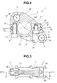
- Fig. 2 is a sectional view of the lower link of the invention, that is taken along the line "II-II" of Fig. 3;
- Fig. 3 is a top view of the lower link of the invention;
- Fig. 4 is a left side view of the lower link of the invention, that is taken from the direction of the arrow "IV" of Fig. 3;
- Fig. 5 is a right side view of the lower link of the invention, that is taken from the direction of the arrow "V" of Fig. 3; and
- Fig. 6 is a view similar to Fig. 5, but showing a condition wherein a certain load is applied to the lower link of the invention from a crank pin of a crankshaft.
-
- In the following, the present invention will be described in detail with reference to the accompanying drawings.
- For ease of understanding, various directional terms, such as upper, lower, right, left, upward and the like are used in the description. However, such terms are to be understood with respect to a drawing or drawing on which a corresponding part or portion is shown.
- Referring to the accompanying drawings, particularly Figs. 1 and 2, there is shown a
lower link 1 of the present invention. - This
lower link 1 is used as an element of a double link type piston crank mechanism, such as the mechanism described in the above-mentioned Laid-open Japanese Patent Applications. - As is seen from Fig. 2 which is a sectional view taken along the line "II-II" of Fig. 3, the
lower link 1 has a split construction, including an upper half-part 2 and a lower half-part 3 which are tightly coupled by means of twobolts 4ad 5 at mutually mating surfaces indicated by the phantom line "H". - When
lower link 1 is properly set with respect to an associated internal combustion engine (not shown), upper half-part 2 and lower half-part 3 oflower link 1 are arranged at upper and lower positions in an associated crankcase (not shown), and twobolts parts numerals parts - Denoted by
numeral 6 is a pin bore into which an upper pin (not shown) of an upper link (not shown) is inserted for achieving a pivotal connection betweenlower link 1 and the upper link. - As is seen from Figs. 1 and 3,
pin bore 6 is defined by anannular boss portion 7 integrally formed on an upper portion oflower link 1. - The upper link incorporated with
lower link 1 of the invention has a forked lower end including two spaced arms that has aligned pin bores for receiving the upper pin. The aligned pin bores of the two spaced arms have chamfered inside ends by which opposed outer surface portions ofannular boss portion 7 oflower link 7 are rotatably held. - Referring back to Fig. 2, denoted by
numeral 8 is a pin bore into which a control pin (not shown) of a control link (not shown) is inserted for achieving a pivotal connection betweenlower link 1 and the control link. - As is seen from Figs. 1 and 3,
pin bore 8 is defined by anannular boss portion 9 integrally formed on a lower portion oflower link 1. More specifically, as is seen from Fig. 3,annular boss portion 9 has a forked end including two spacedwalls 42 that have aligned pin bores for receiving the control pin. The aligned pin bores of two spacedwalls 42 have chamfered inside ends by which opposed outer surface portions of an annular boss formed on the control link are rotatably held. - Referring back to Fig. 2, denoted by
numeral 10 is a pin bore into which a crank pin (not shown) of a crankshaft (not shown) is inserted for achieving a pivotal connection betweenlower link 1 and the crankshaft. - It is to be noted that the split line "H" of
lower link 1 at which upper and lower half-parts center 10C of the pin bore 10. - As is seen from Figs. 1 and 2,
pin bore 10 for crank pin is defined by an annular bearinghousing portion 11 that is integrally formed on a middle portion oflower link 1. - As is understood from Fig. 3, annular bearing
housing portion 11 has a thickness larger than that ofannular boss portion 7 for the upper link. Due to the larger thickness, the annular bearinghousing portion 11 has a satisfied rigidity. - As is seen from Fig. 2, for receiving the two
bolts part 2 oflower link 1 is formed with two internally threadedbores part 3 oflower link 1 is formed with twobored portions bolts bores part 2. -
Portions part 2 that have the internally threadedbores portions part 3 that have thebored portions bolts bores part 2. - As is understood from Fig. 1,
such portions such portions lower link 1. As shown, each of theportions lower link 1. - In order to clarify the feature of the present invention, description will be directed to "minimum reference contour" MRC that is possessed by conventional lower links such as those disclosed by the above-mentioned Laid-open Japanese Patent Applications.
- For providing
lower link 1 of the invention with a satisfied rigidity and a reliable dimensional stability,lower link 1 has also minimum reference contour MRC. - That is, as is indicated by a chain line in Fig. 1, in case of
lower link 1, the minimum reference contour MRC is defined by a continuous straight line that passes an outer edge portion ofannular boss portion 7 for the upper pin, that ofannular boss portion 9 for the control pin, that of bearinghousing portion 11 for the crank pin, that ofportions portions bored portions - It is to be noted that in case of the above-mentioned conventional lower links, there are substantially no portions that extend radially outward beyond the minimum reference contour MRC.
- However, as is seen from Fig. 1, in the present invention, the
lower link 1 has further portions that are positioned outside of the minimum reference contour MRC. That is, amiddle section 21 that integrally connectsannular boss portion 7 for the upper pin and bearinghousing portion 11 for the crank pin has, at a section thereof facing an associated piston (not shown), azone 22 that has a projectedportion 23 that projects radially outward from the minimum reference contour MRC. - It is to be noted that an apex 24 of the projected portion 23 (that is, the point where the maximum distance is provided between the minimum reference contour MRC and the projected portion 23) is positioned at the side of the pin bore 6 (or upper pin) with respect to a normal bisector L28 of a straight line segment L27 that connects a
center 6C of pin bore 6 (or upper pin) and thecenter 10C of pin bore 10 (or crank pin). - Due to provision of the projected
portion 23 that has the above-mentioned geometrical feature, the following advantage is obtainable. - That is, when, under combustion stroke of an associated piston, a load indicated by the arrow L1 is applied from the upper pin rotatably received in pin bore 6 to
lower link 1 and at the same time a load indicated by the arrow L2 is applied from the crank pin rotatably received in pin bore 10 tolower link 1, themiddle section 21 oflower link 1 that connects theannular boss portion 7 for the upper pin and bearinghousing portion 11 for the crank pin is subjected to a certain shearing load. However, due to provision ofzone 22 with the projectedportion 23, that is, because such shearing load is appropriately supported by a larger portion oflower link 1 that is defined between straight line segment L27 and projectedportion 23, undesirable deformation and damage oflower link 1 are suppressed or at least minimized. - As is seen from Fig. 1, another
middle section 31 that integrally connectsannular boss portion 9 for the control pin and bearinghousing portion 11 for the crank pin has, at a section thereof facing a base part of the associated control link (not shown), azone 32 that has a projectedportion 33 that projects radially outward from the minimum reference contour MRC. - It is to be noted that an apex 34 (that is, the point where the maximum distance is provided between the minimum reference contour MRC and the projected portion 33) is positioned nearer to the pin bore 8 (or control pin) than a normal bisector L37 of a straight line segment L36 that connects a
center 8C of pin bore 8 (or control pin) and thecenter 10C of pin bore 10 (or crank pin) is. - Due to provision of the projected
portion 33 that has the above-mentioned geometrical feature, the following advantage is obtainable. - That is, when, under combustion stroke of an associated piston, a load indicated by the arrow L3 is applied from the crank pin rotatably received in pin bore 8 to
lower link 1 and at the same a load indicated by the arrow L2 is applied from the crank pin rotatably received in pin bore 10 tolower link 1, themiddle section 31 is subjected to a tension load (or tensile stress). Due to this tension load,annular boss portion 9 for the control pin tends to show a deformation in the direction of the arrow L3, and thus, the two spacedwalls 42 that constitute the forked end ofannular boss portion 9 tend to induce an inward deformation thereof. However, in the present invention, such inward deformation of the two spacedwalls 42 is suppressed or at least minimized due to provision of the projectedportion 33 mentioned hereinabove. - The inward deformation of the two spaced
walls 42 ofannular boss portion 9 will be discussed in detail with reference to Fig. 6. - When no external force is applied to the two spaced
walls 42 of theannular boss portion 9, the structure that surroundsannular boss portion 9 shows such a condition that two spacedwalls 42 extend downward straightly from a straight mating surface (indicated by broken line 41) of lower half-part 3 oflower link 1 at which the upper half-part 2 oflower link 1 contacts lower half-part 3. While, when an external force is applied to two spacedwalls 42,mating surface 41 of lower half-part 3 that contacts upper half-part 2 is curved to become convex in shape as is exaggeratedly shown bysolid line 43. With such convex shaping ofmating surface 41, two spacedwalls 42 are deformed inward toward each other as is exaggeratedly shown bysolid lines 44. - However, in the present invention, due to provision of the projected
portion 33, the undesired inward deformation of two spacedwalls 42 is suppressed or at least minimized. In other words, the portion oflower link 1 that surrounds the apex 34 serves as a reinforcing means of theannular boss portion 9 oflower link 1. - As is seen from Fig. 1, pin bore 10 for the crank pin is formed in an area of
lower link 1 where a center of gravity is provided. This is advantageous for reducing undesired vibration oflower link 1 relative to the crank pin. - As is seen from Fig. 1, the projected
portion 23 and the other projectedportion 33 are arranged at generally opposite positions with respect to thecenter 10C of pin bore 10 for the crank pin. This arrangement promotes reduction of the undesired vibration oflower link 1. - As is seen from Fig. 1,
lower link 1 is integrally formed, at an outer side ofannular boss portion 7 for the upper pin, with a projectedportion 40. That is, projectedportion 40 is located on an extended part of the straight line segment L27 that connects acenter 6C of pin bore 6 for the upper pin andcenter 10C of pin bore 10 for the crank pin. As is seen from Figs. 3 and 4, projectedportion 40 is thinner than theannular boss portion 7. - Due to provision of projected
portion 40 that has the above-mentioned geometrical feature, the following advantage is obtainable. - That is, when, under combustion stroke of the associated piston, a load indicated by the arrow L1 is applied from the upper pin rotatably received in pin bore 6 to
lower link 1,annular boss portion 7 is subjected to a tension load (or tensile stress). Due to this tension load,annular boss portion 7 for the upper pin tends to show a deformation in the direction of the arrow L1. However, in the present invention, such deformation is suppressed or at least minimized by the provision of the projectedportion 40. Furthermore, due to the thinner structure of such projectedportion 40, weight oflower link 1 and moment of inertia of the same can be reduced. It is to be noted that providinglower link 1 with such projectedportion 40 is more effective in increasing the rigidity oflower link 1 than increasing the diameter ofannular boss portion 7 so long as such two measures cause an even increase in weight oflower link 1. This is because the provision of such projectedportion 40 brings about a higher modulus of section than the diameter increase ofannular boss portion 7. - The entire contents of Japanese Patent Application 2003-193305 filed July 8, 2003 are incorporated herein by reference.
- Although the invention has been described above with reference to the embodiment of the invention, the invention is not limited to such embodiment as described above. Various modifications and variations of such embodiment may be carried out by those skilled in the art, in light of the above description.
Claims (11)
- A lower link (1) for use in a piston crank mechanism of an internal combustion engine, the piston crank mechanism including an upper link that has one end pivotally connected to a piston through a piston pin, the lower link (1) that is of a split type including upper and lower half-parts (2, 3) coupled by a bolt (4, 5) and is pivotally connected to the other end of the upper link through an upper pin and pivotally disposed on a crank pin of a crankshaft and a control link that has one end pivotally connected to a fixed portion of the engine and the other end pivotally connected to the lower link (1) through a control pin,
the lower link (1) comprising:a crank pin bearing housing portion (11) adapted to receive the crank pin, the crank pin bearing housing portion (11) defining a first contour;an upper pin receiving bore portion (6) adapted to receive the upper pin, the upper pin receiving bore portion (6) defining a second contour;a control pin receiving bore portion (8) adapted to receive the control pin, the control pin receiving bore portion (8) defining a third contour;a given portion that has therein an internally threaded bore (12, 13) formed in one of the upper and lower half-parts (2, 3) of the lower link (1) and a bored portion (14, 15) formed in the other of the upper and lower half-parts (2, 3) of the lower link (1), the given portion defining a fourth contour, the upper and lower half-parts (2, 3) being coupled by the bolt (4, 5) that passes through the bored portion (14, 15) and is engaged with the internally threaded bore (12, 13); andradially projected portions (23, 33, 40) that extend radially outward beyond an imaginary minimum reference contour (MRC) that is provided by connecting outer edge portions of the first, second, third and fourth contours with a continuous line. - The lower link as claimed in Claim 1, in which the crank pin bearing housing portion (11), the upper pin receiving bore portion (6) and the control pin receiving bore portion (8) are each formed to have a cylindrical bore to rotatably receiving therein the corresponding pin.
- The lower link as claimed in Claim 1 or 2, in which the fourth contour defined by the given portion has a size that is larger than that of a contour defined by the corresponding bolt.
- The lower link as claimed in Claim 1, 2 or 3, in which an apex (24) of one (23) of the radially projected portions (23, 33, 40) is positioned at the side of the upper pin receiving portion (6) with respect to a normal bisector (L28) of a straight line segment (L27) that connects a center (6C) of the upper pin receiving portion (6) and a center (10C) of the crank pin bearing housing portion (11).
- The lower link as claimed in Claim 4, in which the apex (24) of the radially projected portion (24) is positioned to face a back side of a corresponding piston of the engine.
- The lower link as claimed in Claim 1,2 or 3, in which an apex (34) of one (33) of the radially projected portions (23, 33, 40) is positioned at the side of the control pin receiving bore portion (8) with respect to a normal bisector (L37) of a straight line segment (L36) that connects a center (8C) of the control pin receiving bore portion (8) and a center (10C) of the crank pin bearing housing portion (11).
- The lower link as claimed in Claim 6, in which the apex (34) of the radially projected portion (33) is positioned to face toward a lower end of the control link that is pivotally connected to a fixed member of the engine.
- The lower link as claimed in Claim 1, 2 or 3, in which:an apex (24) of one (23) the radially projected portions (23, 33, 40) is positioned at the side of the upper pin receiving portion (6) with respect to a normal bisector (L28) of a straight line segment (L27) that connects a center (6C) of the upper pin receiving portion (6) and a center (10C) of the crank pin bearing housing portion (11), and in which,an apex (34) of the other one (33) of the radially projected portions (23, 33, 40) is positioned at the side of the control pin receiving bore portion (8) with respect to a normal bisector (L37) of a straight line segment (L36) that connects a center (8C) of control pin receiving bore portion (8) and a center (10C) of the crank pin bearing housing portion (11).
- The lower link as claimed in Claim 8, in which still another one (40) of the radially projected portions (23, 33, 40) is positioned at an outer side of the upper pin receiving bore portion (6).
- The lower link as claimed in Claim 9, in which the still another one (40) of the radially projected portions (23, 33, 40) is thinner than the upper pin receiving bore portion (6).
- A lower link (1) for use in a piston crank mechanism of an internal combustion engine, the piston crank mechanism including an upper link that has one end pivotally connected to a piston through a piston pin, the lower link (1) that is of a split type including upper and lower half-parts (2, 3) coupled by a bolt (4, 5) and is pivotally connected to the other end of the upper link through an upper pin and pivotally disposed on a crank pin of a crankshaft and a control link that has one end pivotally connected to a fixed portion of the engine and the other end pivotally connected to the lower link (1) through a control pin,
the lower link (1) comprising:a crank pin bearing housing portion (11) adapted to receive the crank pin, the crank pin bearing housing portion (11) defining a first contour;an upper pin receiving bore portion (6) adapted to receive the upper pin, the upper pin receiving bore portion (6) defining a second contour;a control pin receiving bore portion (8) adapted to receive the control pin, the control pin receiving bore portion (8) defining a third contour;a given portion that has therein an internally threaded bore (12, 13) formed in one of the upper and lower half-parts (2, 3) of the lower link (1) and a bored portion (14, 15) formed in the other of the upper and lower half-parts (2, 3) of the lower link (1), the given portion defining a fourth contour, the upper and lower half-parts (2, 3) being coupled by the bolt (4, 5) that passes through the bored portion (14, 15) and is engaged with the internally threaded bore (12, 13); andfirst, second and third radially projected portions (23, 33, 40) that extend radially outward beyond an imaginary minimum reference contour (MRC) that is provided by connecting outer edge portions of the first, second, third and fourth contours with a continuous line,the first radially projected portion (23) having an apex (24) that is positioned at the side of the upper pin receiving portion (6) with respect to a normal bisector (L28) of a straight line segment (L27) that connects a center (6C) of the upper pin receiving portion (6) and a center (10C) of the crank pin bearing housing portion (11),the second radially projected portion (33) having an apex (34) that is positioned at the side of the control pin receiving bore portion (8) with respect to a normal bisector (L37) of a straight line segment (L36) that connects a center (8C) of the control pin receiving bore portion (8) and the center (10C) of the crank pin bearing housing portion (11), andthe third radially projected portion (40) being positioned at an outer side of the upper pin receiving bore portion (6).
Applications Claiming Priority (2)
| Application Number | Priority Date | Filing Date | Title |
|---|---|---|---|
| JP2003193305A JP4148046B2 (en) | 2003-07-08 | 2003-07-08 | Lower link in piston crank mechanism of internal combustion engine |
| JP2003193305 | 2003-07-08 |
Publications (3)
| Publication Number | Publication Date |
|---|---|
| EP1496218A2 true EP1496218A2 (en) | 2005-01-12 |
| EP1496218A3 EP1496218A3 (en) | 2009-09-30 |
| EP1496218B1 EP1496218B1 (en) | 2017-02-01 |
Family
ID=33447978
Family Applications (1)
| Application Number | Title | Priority Date | Filing Date |
|---|---|---|---|
| EP04015253.0A Active EP1496218B1 (en) | 2003-07-08 | 2004-06-29 | Lower link of piston crank mechanism for internal combustion engine |
Country Status (3)
| Country | Link |
|---|---|
| US (1) | US7021269B2 (en) |
| EP (1) | EP1496218B1 (en) |
| JP (1) | JP4148046B2 (en) |
Cited By (1)
| Publication number | Priority date | Publication date | Assignee | Title |
|---|---|---|---|---|
| EP1801387A1 (en) * | 2005-12-20 | 2007-06-27 | Nissan Motor Company Limited | Lower link for piston crank mechanism of internal combustion engine |
Families Citing this family (6)
| Publication number | Priority date | Publication date | Assignee | Title |
|---|---|---|---|---|
| JP4654514B2 (en) * | 2000-12-26 | 2011-03-23 | 日産自動車株式会社 | Piston crank mechanism for reciprocating internal combustion engine |
| JP4613607B2 (en) * | 2004-12-24 | 2011-01-19 | 日産自動車株式会社 | Lower link in piston crank mechanism of internal combustion engine |
| JP7109202B2 (en) * | 2018-01-31 | 2022-07-29 | 日産自動車株式会社 | Lower link in variable compression ratio mechanism of internal combustion engine |
| CN110285136A (en) * | 2019-06-28 | 2019-09-27 | 长城汽车股份有限公司 | Lower link and engine with it |
| CN110284966B (en) * | 2019-06-28 | 2021-04-20 | 长城汽车股份有限公司 | Lower connecting rod and engine with same |
| CN110159426B (en) * | 2019-06-28 | 2021-04-20 | 长城汽车股份有限公司 | Engine assembling method and engine |
Citations (4)
| Publication number | Priority date | Publication date | Assignee | Title |
|---|---|---|---|---|
| JP2000054873A (en) | 1998-08-10 | 2000-02-22 | Toyota Motor Corp | Internal combustion engine having variable compression ratio mechanism |
| JP2001227367A (en) | 2000-02-16 | 2001-08-24 | Nissan Motor Co Ltd | Reciprocating internal combustion engine |
| EP1180588A2 (en) | 2000-08-14 | 2002-02-20 | Nissan Motor Co., Ltd. | Piston crank mechanism of reciprocating internal combustion engine |
| JP2002061501A (en) | 2000-08-17 | 2002-02-28 | Nissan Motor Co Ltd | Dual link mechanism for internal combustion engine |
Family Cites Families (5)
| Publication number | Priority date | Publication date | Assignee | Title |
|---|---|---|---|---|
| US5890465A (en) * | 1996-11-01 | 1999-04-06 | Williams; Kenneth A. | Internal combustion engine with optimum torque output |
| WO2002012694A1 (en) * | 2000-08-08 | 2002-02-14 | Daimlerchrysler Ag | Internal combustion piston engine comprising various compression influences |
| JP3882643B2 (en) * | 2001-04-05 | 2007-02-21 | 日産自動車株式会社 | Variable compression ratio mechanism of internal combustion engine |
| JP4096700B2 (en) * | 2002-11-05 | 2008-06-04 | 日産自動車株式会社 | Variable compression ratio device for internal combustion engine |
| JP4092495B2 (en) * | 2003-08-28 | 2008-05-28 | 日産自動車株式会社 | Double link type piston-crank mechanism for internal combustion engine |
-
2003
- 2003-07-08 JP JP2003193305A patent/JP4148046B2/en not_active Expired - Fee Related
-
2004
- 2004-06-29 EP EP04015253.0A patent/EP1496218B1/en active Active
- 2004-07-07 US US10/885,013 patent/US7021269B2/en active Active
Patent Citations (4)
| Publication number | Priority date | Publication date | Assignee | Title |
|---|---|---|---|---|
| JP2000054873A (en) | 1998-08-10 | 2000-02-22 | Toyota Motor Corp | Internal combustion engine having variable compression ratio mechanism |
| JP2001227367A (en) | 2000-02-16 | 2001-08-24 | Nissan Motor Co Ltd | Reciprocating internal combustion engine |
| EP1180588A2 (en) | 2000-08-14 | 2002-02-20 | Nissan Motor Co., Ltd. | Piston crank mechanism of reciprocating internal combustion engine |
| JP2002061501A (en) | 2000-08-17 | 2002-02-28 | Nissan Motor Co Ltd | Dual link mechanism for internal combustion engine |
Cited By (2)
| Publication number | Priority date | Publication date | Assignee | Title |
|---|---|---|---|---|
| EP1801387A1 (en) * | 2005-12-20 | 2007-06-27 | Nissan Motor Company Limited | Lower link for piston crank mechanism of internal combustion engine |
| US7290508B2 (en) | 2005-12-20 | 2007-11-06 | Nissan Motor Co., Ltd. | Lower link for piston crank mechanism of internal combustion engine |
Also Published As
| Publication number | Publication date |
|---|---|
| EP1496218B1 (en) | 2017-02-01 |
| JP4148046B2 (en) | 2008-09-10 |
| US7021269B2 (en) | 2006-04-04 |
| JP2005030438A (en) | 2005-02-03 |
| US20050005897A1 (en) | 2005-01-13 |
| EP1496218A3 (en) | 2009-09-30 |
Similar Documents
| Publication | Publication Date | Title |
|---|---|---|
| JP3882643B2 (en) | Variable compression ratio mechanism of internal combustion engine | |
| EP2053217B1 (en) | Multi-Link Engine | |
| EP1496218B1 (en) | Lower link of piston crank mechanism for internal combustion engine | |
| US20060137629A1 (en) | Lower link for piston crank mechanism of engine | |
| EP1247959A2 (en) | Piston control mechanism of reciprocating internal combustion engine of variable compression ratio type | |
| JP2004124775A (en) | Variable compression ratio mechanism for internal combustion engine | |
| JP2004124776A (en) | Variable compression ratio mechanism and link parts for internal combustion engine | |
| CN104989526B (en) | Crosshead of crosshead diesel engine and crosshead diesel engine | |
| KR101554379B1 (en) | Piston bearing arrangement | |
| JP2008208783A (en) | Bearing structure for link mechanism | |
| KR101398769B1 (en) | Cross head for cross head type diesel engine | |
| JP4380321B2 (en) | Lower link in piston crank mechanism of internal combustion engine | |
| JP4506340B2 (en) | Lower link in piston crank mechanism of internal combustion engine | |
| JP4374992B2 (en) | Bearing assembly of link mechanism and manufacturing method thereof | |
| JP4654514B2 (en) | Piston crank mechanism for reciprocating internal combustion engine | |
| JP4259214B2 (en) | Variable compression ratio mechanism of internal combustion engine | |
| EP3763925A1 (en) | Variable-compression-ratio internal combustion engine | |
| JP3695107B2 (en) | Piston and piston pin | |
| JP2003097288A (en) | Adjustable compression ratio mechanism of internal combustion engine | |
| JP3460296B2 (en) | Connecting rod | |
| JP4245328B2 (en) | Piston for internal combustion engine | |
| JPH0144750Y2 (en) | ||
| JP2002155921A (en) | Link rod for internal combustion engine | |
| KR19990010859A (en) | Connecting rod structure | |
| JP2568898B2 (en) | Engine assembly structure and assembly method |
Legal Events
| Date | Code | Title | Description |
|---|---|---|---|
| PUAI | Public reference made under article 153(3) epc to a published international application that has entered the european phase |
Free format text: ORIGINAL CODE: 0009012 |
|
| 17P | Request for examination filed |
Effective date: 20040629 |
|
| AK | Designated contracting states |
Kind code of ref document: A2 Designated state(s): AT BE BG CH CY CZ DE DK EE ES FI FR GB GR HU IE IT LI LU MC NL PL PT RO SE SI SK TR |
|
| AX | Request for extension of the european patent |
Extension state: AL HR LT LV MK |
|
| PUAL | Search report despatched |
Free format text: ORIGINAL CODE: 0009013 |
|
| AK | Designated contracting states |
Kind code of ref document: A3 Designated state(s): AT BE BG CH CY CZ DE DK EE ES FI FR GB GR HU IE IT LI LU MC NL PL PT RO SE SI SK TR |
|
| AX | Request for extension of the european patent |
Extension state: AL HR LT LV MK |
|
| AKX | Designation fees paid |
Designated state(s): DE FR GB |
|
| 17Q | First examination report despatched |
Effective date: 20100719 |
|
| APBK | Appeal reference recorded |
Free format text: ORIGINAL CODE: EPIDOSNREFNE |
|
| APBN | Date of receipt of notice of appeal recorded |
Free format text: ORIGINAL CODE: EPIDOSNNOA2E |
|
| APBR | Date of receipt of statement of grounds of appeal recorded |
Free format text: ORIGINAL CODE: EPIDOSNNOA3E |
|
| APAF | Appeal reference modified |
Free format text: ORIGINAL CODE: EPIDOSCREFNE |
|
| APBT | Appeal procedure closed |
Free format text: ORIGINAL CODE: EPIDOSNNOA9E |
|
| GRAP | Despatch of communication of intention to grant a patent |
Free format text: ORIGINAL CODE: EPIDOSNIGR1 |
|
| INTG | Intention to grant announced |
Effective date: 20160926 |
|
| GRAS | Grant fee paid |
Free format text: ORIGINAL CODE: EPIDOSNIGR3 |
|
| GRAA | (expected) grant |
Free format text: ORIGINAL CODE: 0009210 |
|
| AK | Designated contracting states |
Kind code of ref document: B1 Designated state(s): DE FR GB |
|
| REG | Reference to a national code |
Ref country code: GB Ref legal event code: FG4D |
|
| REG | Reference to a national code |
Ref country code: DE Ref legal event code: R096 Ref document number: 602004050718 Country of ref document: DE |
|
| REG | Reference to a national code |
Ref country code: FR Ref legal event code: PLFP Year of fee payment: 14 |
|
| REG | Reference to a national code |
Ref country code: DE Ref legal event code: R097 Ref document number: 602004050718 Country of ref document: DE |
|
| PLBE | No opposition filed within time limit |
Free format text: ORIGINAL CODE: 0009261 |
|
| STAA | Information on the status of an ep patent application or granted ep patent |
Free format text: STATUS: NO OPPOSITION FILED WITHIN TIME LIMIT |
|
| 26N | No opposition filed |
Effective date: 20171103 |
|
| REG | Reference to a national code |
Ref country code: FR Ref legal event code: PLFP Year of fee payment: 15 |
|
| PGFP | Annual fee paid to national office [announced via postgrant information from national office to epo] |
Ref country code: GB Payment date: 20220506 Year of fee payment: 19 Ref country code: FR Payment date: 20220510 Year of fee payment: 19 Ref country code: DE Payment date: 20220505 Year of fee payment: 19 |
|
| REG | Reference to a national code |
Ref country code: DE Ref legal event code: R119 Ref document number: 602004050718 Country of ref document: DE |
|
| GBPC | Gb: european patent ceased through non-payment of renewal fee |
Effective date: 20230629 |
|
| PG25 | Lapsed in a contracting state [announced via postgrant information from national office to epo] |
Ref country code: DE Free format text: LAPSE BECAUSE OF NON-PAYMENT OF DUE FEES Effective date: 20240103 Ref country code: GB Free format text: LAPSE BECAUSE OF NON-PAYMENT OF DUE FEES Effective date: 20230629 |