EP1496209B1 - Lageranordnung für eine Gasturbine - Google Patents
Lageranordnung für eine Gasturbine Download PDFInfo
- Publication number
- EP1496209B1 EP1496209B1 EP04015747.1A EP04015747A EP1496209B1 EP 1496209 B1 EP1496209 B1 EP 1496209B1 EP 04015747 A EP04015747 A EP 04015747A EP 1496209 B1 EP1496209 B1 EP 1496209B1
- Authority
- EP
- European Patent Office
- Prior art keywords
- oil
- bearing ring
- permeable element
- bearing
- bearing arrangement
- Prior art date
- Legal status (The legal status is an assumption and is not a legal conclusion. Google has not performed a legal analysis and makes no representation as to the accuracy of the status listed.)
- Expired - Lifetime
Links
- 238000005096 rolling process Methods 0.000 claims description 18
- 238000001816 cooling Methods 0.000 claims description 4
- 238000005461 lubrication Methods 0.000 claims description 4
- 210000001331 nose Anatomy 0.000 description 4
- 239000000919 ceramic Substances 0.000 description 1
- 238000004939 coking Methods 0.000 description 1
- 230000001419 dependent effect Effects 0.000 description 1
- 230000003993 interaction Effects 0.000 description 1
- 239000002184 metal Substances 0.000 description 1
- 239000011148 porous material Substances 0.000 description 1
- 238000005086 pumping Methods 0.000 description 1
Images

Classifications
-
- F—MECHANICAL ENGINEERING; LIGHTING; HEATING; WEAPONS; BLASTING
- F01—MACHINES OR ENGINES IN GENERAL; ENGINE PLANTS IN GENERAL; STEAM ENGINES
- F01D—NON-POSITIVE DISPLACEMENT MACHINES OR ENGINES, e.g. STEAM TURBINES
- F01D25/00—Component parts, details, or accessories, not provided for in, or of interest apart from, other groups
- F01D25/08—Cooling; Heating; Heat-insulation
- F01D25/12—Cooling
- F01D25/125—Cooling of bearings
-
- F—MECHANICAL ENGINEERING; LIGHTING; HEATING; WEAPONS; BLASTING
- F01—MACHINES OR ENGINES IN GENERAL; ENGINE PLANTS IN GENERAL; STEAM ENGINES
- F01D—NON-POSITIVE DISPLACEMENT MACHINES OR ENGINES, e.g. STEAM TURBINES
- F01D25/00—Component parts, details, or accessories, not provided for in, or of interest apart from, other groups
- F01D25/16—Arrangement of bearings; Supporting or mounting bearings in casings
-
- F—MECHANICAL ENGINEERING; LIGHTING; HEATING; WEAPONS; BLASTING
- F16—ENGINEERING ELEMENTS AND UNITS; GENERAL MEASURES FOR PRODUCING AND MAINTAINING EFFECTIVE FUNCTIONING OF MACHINES OR INSTALLATIONS; THERMAL INSULATION IN GENERAL
- F16C—SHAFTS; FLEXIBLE SHAFTS; ELEMENTS OR CRANKSHAFT MECHANISMS; ROTARY BODIES OTHER THAN GEARING ELEMENTS; BEARINGS
- F16C33/00—Parts of bearings; Special methods for making bearings or parts thereof
- F16C33/30—Parts of ball or roller bearings
- F16C33/66—Special parts or details in view of lubrication
- F16C33/6637—Special parts or details in view of lubrication with liquid lubricant
- F16C33/6659—Details of supply of the liquid to the bearing, e.g. passages or nozzles
- F16C33/6677—Details of supply of the liquid to the bearing, e.g. passages or nozzles from radial inside, e.g. via a passage through the shaft and/or inner ring
-
- F—MECHANICAL ENGINEERING; LIGHTING; HEATING; WEAPONS; BLASTING
- F16—ENGINEERING ELEMENTS AND UNITS; GENERAL MEASURES FOR PRODUCING AND MAINTAINING EFFECTIVE FUNCTIONING OF MACHINES OR INSTALLATIONS; THERMAL INSULATION IN GENERAL
- F16C—SHAFTS; FLEXIBLE SHAFTS; ELEMENTS OR CRANKSHAFT MECHANISMS; ROTARY BODIES OTHER THAN GEARING ELEMENTS; BEARINGS
- F16C33/00—Parts of bearings; Special methods for making bearings or parts thereof
- F16C33/30—Parts of ball or roller bearings
- F16C33/66—Special parts or details in view of lubrication
- F16C33/6637—Special parts or details in view of lubrication with liquid lubricant
- F16C33/6685—Details of collecting or draining, e.g. returning the liquid to a sump
-
- F—MECHANICAL ENGINEERING; LIGHTING; HEATING; WEAPONS; BLASTING
- F16—ENGINEERING ELEMENTS AND UNITS; GENERAL MEASURES FOR PRODUCING AND MAINTAINING EFFECTIVE FUNCTIONING OF MACHINES OR INSTALLATIONS; THERMAL INSULATION IN GENERAL
- F16C—SHAFTS; FLEXIBLE SHAFTS; ELEMENTS OR CRANKSHAFT MECHANISMS; ROTARY BODIES OTHER THAN GEARING ELEMENTS; BEARINGS
- F16C19/00—Bearings with rolling contact, for exclusively rotary movement
- F16C19/02—Bearings with rolling contact, for exclusively rotary movement with bearing balls essentially of the same size in one or more circular rows
- F16C19/04—Bearings with rolling contact, for exclusively rotary movement with bearing balls essentially of the same size in one or more circular rows for radial load mainly
- F16C19/06—Bearings with rolling contact, for exclusively rotary movement with bearing balls essentially of the same size in one or more circular rows for radial load mainly with a single row or balls
-
- F—MECHANICAL ENGINEERING; LIGHTING; HEATING; WEAPONS; BLASTING
- F16—ENGINEERING ELEMENTS AND UNITS; GENERAL MEASURES FOR PRODUCING AND MAINTAINING EFFECTIVE FUNCTIONING OF MACHINES OR INSTALLATIONS; THERMAL INSULATION IN GENERAL
- F16C—SHAFTS; FLEXIBLE SHAFTS; ELEMENTS OR CRANKSHAFT MECHANISMS; ROTARY BODIES OTHER THAN GEARING ELEMENTS; BEARINGS
- F16C2360/00—Engines or pumps
- F16C2360/23—Gas turbine engines
-
- Y—GENERAL TAGGING OF NEW TECHNOLOGICAL DEVELOPMENTS; GENERAL TAGGING OF CROSS-SECTIONAL TECHNOLOGIES SPANNING OVER SEVERAL SECTIONS OF THE IPC; TECHNICAL SUBJECTS COVERED BY FORMER USPC CROSS-REFERENCE ART COLLECTIONS [XRACs] AND DIGESTS
- Y02—TECHNOLOGIES OR APPLICATIONS FOR MITIGATION OR ADAPTATION AGAINST CLIMATE CHANGE
- Y02T—CLIMATE CHANGE MITIGATION TECHNOLOGIES RELATED TO TRANSPORTATION
- Y02T50/00—Aeronautics or air transport
- Y02T50/60—Efficient propulsion technologies, e.g. for aircraft
Definitions
- the invention relates to a bearing arrangement for a gas turbine, in particular for an aircraft engine, according to the preamble of patent claim 1.
- Gas turbines in particular aircraft engines, are operated at high speeds.
- a rotor rotates with respect to a stationary stator, with the rotatability of the rotor relative to the stator ensured by sophisticated bearing arrangements.
- a bearing arrangement for a gas turbine is known.
- the DE 36 04 625 C2 is arranged on a rotor designed as a bearing bearing, wherein the rolling bearing via an inner bearing ring on the rotor and an outer bearing ring on a stator, namely a housing, engages.
- the rolling bearing via an inner bearing ring on the rotor and an outer bearing ring on a stator, namely a housing, engages.
- Between the inner bearing ring and the outer bearing ring are according to the DE 36 04 625 C2 Arranged rolling elements.
- the present invention is based on the problem of proposing a novel bearing arrangement for a gas turbine.
- the rolling bodies for the lubrication and / or cooling of oil is flowed around, wherein at least one permeable, preferably grid-shaped, element surrounds the bearing arrangement for targeted removal of the oil at least partially.
- the oil flowing around the rolling elements impinges on an inside of the or each permeable element, flows through the or each permeable element and is specifically dischargeable as an oil flow on an outside of the or each permeable element. Fogging of the oil in the bearing assembly is minimized by the invention so that power losses on the gas turbine are minimized.
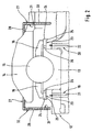
- FIG. 1 shows a cross section through a gas turbine in the neckline with a bearing assembly according to the invention.
- Fig. 2 shows an enlarged detail of the representation of Fig. 1 ,
- Fig. 1 shows a rotor 10 of a gas turbine designed as an aircraft engine, wherein the rotor 10 has a rotation axis 11.
- the rotor 10 rotates at high speed with respect to a non-illustrated housing or stator.
- the rotor 10 is rotatably supported by a bearing assembly 12 in the housing or stator.
- the bearing assembly 12 of the embodiment according to Fig. 1 an inner bearing ring 13 and an outer bearing ring 14.
- the inner bearing ring 13 is connected to the rotor 10 and rotates with the same relative to the housing.
- the outer bearing ring 14 is connected to the housing and therefore fixed.
- rolling elements 15 are arranged between the inner, rotating bearing ring 13 and the outer, fixed bearing ring 14 rolling elements 15 are arranged.
- the rolling elements 15 are surrounded by a bearing cage 16, wherein the bearing cage 16 is also disposed between the inner, rotating bearing ring 13 and the outer, stationary bearing ring 14.
- the rolling elements 15 are flowed around by oil.
- Fig. 1 a channel 17 introduced into the rotor 10, which extends in the axial direction of the rotor 10, but is arranged axially offset from the axis of rotation 11 of the rotor 10.
- the arrow 18 is passed through the channel 17 oil.
- the channel extending in the axial direction 17 branch off from the channel 17 also as channels 19, 20 formed from leads, which via these leads in the direction of arrows 21 and 22, the oil is moved in the direction of the bearing assembly 12 of the invention.
- the channels 19 and 20 extend substantially in the radial direction.
- the rotor 10 of the gas turbine is a component rotating at high speed.
- high speeds which are common in aircraft engines or other gas turbines, occur high centrifugal forces or centrifugal forces, which for a pumping action and thus for the flow of the oil through the channels 17, 19 and 20 in the direction of arrows 18, 21 and 22nd to care.
- the oil emerging from the channels 19 and 20 strikes a lower side 23 of lateral projections 24 of the inner bearing ring 13.
- On both sides of the inner bearing ring such a projection 24 is provided in each case.
- the catch noses 25 ensure that the incident on the bottom 23 of the projections 24 oil is held on the bottom 23 and forms an oil film there.
- the projections 24 continue to have holes 26 which penetrate the catch noses 24 in the radial direction.
- the emerging from the channels 19, 20 and impinging on the underside 23 of the projections 24 oil is forced due to the centrifugal forces occurring during rotation by extending in the radial direction bores 26, then strikes the bearing cage 16 and then finally enters the area the rolling elements 15, wherein the rolling elements 15 are then flowed around by the oil.
- the oil flowing around the rolling elements 15 serves to lubricate and cool the bearing arrangement 12.
- the outer, fixed bearing ring 14, two permeable, namely oil-permeable, elements 27 are assigned according to the embodiment shown.
- the oil-permeable elements 27 have according to Fig. 2 over a substantially L-shaped cross-section.
- One leg 28 of the oil-permeable elements 27 extends in the axial direction and is fixedly connected to the fixed, outer bearing ring 14.
- the leg 28 running in the axial direction can also rest on the outer bearing ring 14 and be fastened to the stator.
- Close to the legs 28 are radially extending Legs 29 and 30 of the oil-permeable member 27 at.
- the legs 29 and 30 extend in the radial direction.
- the oil-permeable elements 27 are fixed.
- the oil-permeable elements 27, the bearing assembly 12, namely the outer fixed bearing ring 14, the rolling elements 15 and the inner, rotating bearing ring 13 at least partially or partially enclose. This ensures that the oil flowing around the rolling elements 15 for lubrication and cooling preferably reaches the inside 31 of the oil-permeable elements 27 after the flow around the rolling elements 15. Accordingly, the oil accumulates on the inside 31 of the oil-permeable members 27 and penetrates the same. After passing through the oil-permeable elements 27, the oil collects on an outer side 32 of the same and is on the outer side 32 of the oil-permeable elements 27 as a targeted flow of oil and ordered discharged.
- the oil-permeable elements 27, which enclose the bearing assembly 12 at least in regions it is therefore avoided that the oil flowing around the rolling bearings 15 is sprayed, atomized or foamed in the entire storage space. Rather, the oil is collected by the oil-permeable elements 27 and bundled into an oil film or oil stream, which can be discharged in an orderly manner.
- the bearing arrangement 12 according to the invention therefore, the residence time or the residence time of the oil in the area of the bearings is enormously shortened. Power losses that can occur due to the interaction of the oil with the bearing are avoided. In this respect, power losses at the gas turbine are significantly minimized by the bearing arrangement according to the invention.
- the oil-permeable elements are formed in the illustrated embodiment as a grid-shaped elements 27, preferably as porous sheets, which have a plurality of holes which are introduced into the radially extending legs 29 and 30 and in the axially extending legs 28 of the lattice-shaped element 27. Through these holes, the oil from the inside 31 of the lattice-shaped element on the outside 32 of the same can pass.
- other oil-resistant covers may be used instead of a metal sheet to form an oil-permeable member 27.
- the elements 27 as well Felts be designed as metallic or ceramic brushes, as open-pore sponges or wire mesh.
- the or each oil-permeable element may also have a multiply curved or planar, preferably disk-shaped or annular, cross-section.
- the oil-permeable elements can continue to be made in one piece or in several parts.
- a main advantage of the bearing arrangement according to the invention is that the residence time of the oil in the region of the bearings is shortened and thus power losses of the gas turbine can be minimized. Due to the lower residence time of the oil in the bearing, less heat is still transferred to the oil. Accordingly, in a gas turbine, which has the bearing arrangement according to the invention, smaller oil cooler can be used. As a result, the weight of the gas turbine can be reduced. Reducing the weight of the gas turbine makes it even more efficient. The reduced heat transfer to the oil also reduces the risk of coking and fire on the gas turbine.
Landscapes
- Engineering & Computer Science (AREA)
- General Engineering & Computer Science (AREA)
- Mechanical Engineering (AREA)
- Rolling Contact Bearings (AREA)
Description
- Die Erfindung betrifft eine Lageranordnung für eine Gasturbine, insbesondere für ein Flugzeugtriebwerk, nach dem Oberbegriff des Patentanspruchs 1.
- Gasturbinen, insbesondere Flugzeugtriebwerke, werden bei hohen Drehzahlen betrieben. So rotiert zum Beispiel bei derartigen Flugzeugtriebwerken ein Rotor gegenüber einem feststehenden Stator, wobei die Drehbarkeit des Rotors gegenüber dem Stator durch hochentwickelte Lageranordnungen gewährleistet wird.
- Aus der
DE 36 04 625 C2 ist eine Lageranordnung für eine Gasturbine bekannt. Gemäß derDE 36 04 625 C2 ist auf einem Rotor ein als Wälzlager ausgeführtes Lager angeordnet, wobei das Wälzlager über einen innenliegenden Lagerring an dem Rotor und über einen außenliegenden Lagerring an einem Stator, nämlich an einem Gehäuse, angreift. Zwischen dem innenliegenden Lagerring und dem außenliegenden Lagerring sind gemäß derDE 36 04 625 C2 Wälzkörper angeordnet. - Andere Lageranordnungen gemäß dem Stand der Technik sind aus
EP 0012447 undDE 3345721 bekannt. - Hiervon ausgehend liegt der vorliegenden Erfindung das Problem zu Grunde, eine neuartige Lageranordnung für eine Gasturbine vorzuschlagen.
- Dieses Problem wird dadurch gelöst, dass die eingangs genannte Lageranordnung für eine Gasturbine durch die Merkmale des kennzeichnenden Teils des Patentanspruchs 1 weitergebildet ist.
- Erfindungsgemäß sind die Wälzkörper zur Schmierung und/oder Kühlung von Öl umströmt ist, wobei mindestens ein durchlässiges, vorzugsweise gitterförmiges, Element die Lageranordnung zur gezielten Abführung des Öls zumindest bereichsweise umschließt. Das die Wälzkörper umströmende Öl trifft auf eine Innenseite des oder jeden durchlässigen Elements, durchströmt das oder jedes durchlässige Element und ist auf einer Außenseite des oder jeden durchlässigen Elements als Ölstrom gezielt abführbar. Eine Vernebelung bzw. Verschäumung des Öls in der Lageranordnung wird durch die Erfindung minimiert, so dass Leistungsverluste an der Gasturbine minimiert werden.
- Bevorzugte Weiterbildungen der Erfindung ergeben sich aus den abhängigen Unteransprüchen und der nachfolgenden Beschreibung.
- Ausführungsbeispiele der Erfindung werden, ohne hierauf beschränkt zu sein, an Hand der Zeichnung näher erläutert. In der Zeichnung zeigt:
- Fig. 1:
- einen Querschnitt durch eine erfindungsgemäße Lageranordnung für eine Gasturbine; und
- Fig. 2:
- ein vergrößertes Detail der Darstellung gemäß
Fig. 1 . - Nachfolgend wird die erfindungsgemäße Lageranordnung unter Bezugnahme auf
Fig. 1 und2 in größerem Detail erläutert.Fig. 1 zeigt einen Querschnitt durch eine Gasturbine im Ausschnitt mit einer erfindungsgemäßen Lageranordnung.Fig. 2 zeigt ein vergrößertes Detail der Darstellung derFig. 1 . -
Fig. 1 zeigt einen Rotor 10 einer als Flugzeugtriebwerk ausgebildeten Gasturbine, wobei der Rotor 10 eine Drehachse 11 aufweist. Der Rotor 10 dreht sich mit hoher Drehzahl gegenüber einem nicht-dargestellten Gehäuse bzw. Stator. Der Rotor 10 ist über eine Lageranordnung 12 drehbar im Gehäuse bzw. Stator gelagert. So umfasst die Lageranordnung 12 des Ausführungsbeispiels gemäßFig. 1 einen innenliegenden Lagerring 13 und einen außenliegenden Lagerring 14. Der innenliegende Lagerring 13 ist mit dem Rotor 10 verbunden und dreht sich mit demselben relativ zum Gehäuse. Der außenliegende Lagerring 14 ist mit dem Gehäuse verbunden und daher feststehend. Zwischen dem innenliegenden, rotierenden Lagerring 13 und dem außenliegenden, feststehenden Lagerring 14 sind Wälzkörper 15 angeordnet. Die Wälzkörper 15 sind von einem Lagerkäfig 16 umgeben, wobei der Lagerkäfig 16 ebenfalls zwischen dem innenliegenden, rotierenden Lagerring 13 und dem außenliegenden, feststehenden Lagerring 14 angeordnet ist. - Zur Schmierung und Kühlung der Lageranordnung 12, insbesondere der Wälzkörper 15, werden die Wälzkörper 15 von Öl umströmt. So zeigt
Fig. 1 einen in den Rotor 10 eingebrachten Kanal 17, der sich in axialer Richtung des Rotors 10 erstreckt, jedoch axial versetzt zur Drehachse 11 des Rotors 10 angeordnet ist. Gemäß dem Pfeil 18 wird durch den Kanal 17 Öl geleitet. Ausgehend vom sich in axialer Richtung erstreckenden Kanal 17 zweigen vom Kanal 17 ebenfalls als Kanäle 19, 20 ausgebildete Zuleitungen ab, wobei über diese Zuleitungen im Sinne der Pfeile 21 und 22 das Öl in Richtung auf die erfindungsgemäße Lageranordnung 12 bewegt wird. Die Kanäle 19 und 20 verlaufen im Wesentlichen in radialer Richtung. - Wie bereits erwähnt, handelt es sich bei dem Rotor 10 der Gasturbine um ein mit hoher Drehzahl rotierendes Bauteil. Bei hohen Drehzahlen, die bei Flugzeugtriebwerken bzw. sonstigen Gasturbinen üblich sind, treten hohe Fliehkräfte bzw. Zentrifugalkräfte auf, die für eine Pumpwirkung und damit für die Strömung des Öls durch die Kanäle 17, 19 und 20 im Sinne der Pfeile 18, 21 und 22 sorgen. Das aus den Kanälen 19 und 20 austretende Öl trifft auf eine Unterseite 23 von seitlichen Vorsprüngen 24 des innenliegenden Lagerrings 13. Zu beiden Seiten des innenliegenden Lagerrings ist jeweils ein derartiger Vorsprung 24 vorgesehen. An den seitlichen Enden der Vorsprünge 24 verfügen dieselben über Fangnasen 25. Die Fangnasen 25 sorgen dafür, dass das auf die Unterseite 23 der Vorsprünge 24 auftreffende Öl auf der Unterseite 23 gehalten wird und dort einen Ölfilm bildet. Neben den Fangnasen 25 verfügen die Vorsprünge 24 weiterhin über Bohrungen 26, die die Fangnasen 24 in radialer Richtung durchdringen. Das aus den Kanälen 19, 20 austretende und auf die Unterseite 23 der Vorsprünge 24 auftreffende Öl wird bedingt durch die bei der Rotation auftretenden Fliehkräfte durch sich in radialer Richtung erstreckenden Bohrungen 26 gedrückt, trifft dann auf den Lagerkäfig 16 und gelangt sodann schließlich in den Bereich der Wälzkörper 15, wobei die Wälzkörper 15 dann vom Öl umströmt werden. Das die Wälzkörper 15 umströmende Öl dient der Schmierung und Kühlung der Lageranordnung 12.
- Bei der erfindungsgemäßen Lageranordnung 12 sind gemäß dem gezeigten Ausführungsbeispiel dem außenliegenden, feststehenden Lagerring 14 zwei durchlässige, nämlich öldurchlässige, Elemente 27 zugeordnet. Die öldurchlässigen Elemente 27 verfügen gemäß
Fig. 2 über einen im Wesentlichen L-förmigen Querschnitt. Ein Schenkel 28 der öldurchlässigen Elemente 27 erstreckt sich in axialer Richtung und ist fest mit dem feststehenden, äußeren Lagerring 14 verbunden. Alternativ kann der in axialer Richtung verlaufende Schenkel 28 auch am äußeren Lagerring 14 anliegen und am Stator befestigt sein. An die Schenkel 28 schließen sich radial verlaufende Schenkel 29 und 30 der öldurchlässigen Element 27 an. Die Schenkel 29 und 30 erstrecken sich in radialer Richtung. Die öldurchlässigen Elemente 27 sind feststehend. - Es liegt im Sinne der hier vorliegenden Erfindung, dass die öldurchlässigen Elemente 27 die Lageranordnung 12, nämlich den äußeren, feststehenden Lagerring 14, die Wälzkörper 15 sowie den innenliegenden, rotierenden Lagerring 13 zumindest abschnittsweise bzw. bereichsweise umschließen. Hierdurch ist gewährleistet, dass das die Wälzkörper 15 zur Schmierung und Kühlung umströmende Öl vorzugsweise nach der Umströmung der Wälzkörper 15 auf eine Innenseite 31 der öldurchlässigen Elemente 27 gelangt. Das Öl sammelt sich demnach auf der Innenseite 31 der öldurchlässigen Elemente 27 und durchdringt dieselben. Nach dem Durchdringen der öldurchlässigen Elemente 27 sammelt sich das Öl auf einer Außenseite 32 derselben und ist auf der Außenseite 32 der öldurchlässigen Elemente 27 als Ölstrom gezielt und geordnet abführbar. Mithilfe der öldurchlässigen Elemente 27, welche die Lageranordnung 12 zumindest bereichsweise umschließen, wird demnach vermieden, dass das die Wälzlager 15 umströmende Öl im gesamten Lagerraum verspritzt, vernebelt bzw. verschäumt. Vielmehr wird das Öl von den öldurchlässigen Elementen 27 aufgefangen und zu einem Ölfilm bzw. Ölstrom gebündelt, der geordnet abgeführt werden kann. Mithilfe der erfindungsgemäßen Lageranordnung 12 wird demnach die Verweilzeit bzw. die Residenzzeit des Öls im Bereich der Lager enorm verkürzt. Leistungsverluste, die durch die Interaktion des Öl mit dem Lager auftreten können, werden vermieden. Insofern werden Leistungsverluste an der Gasturbine durch die erfindungsgemäße Lageranordnung deutlich minimiert.
- Die öldurchlässigen Elemente sind im gezeigten Ausführungsbeispiel als gitterförmige Elemente 27, vorzugsweise als poröse Bleche, ausgebildet, welche eine Vielzahl von Löchern aufweisen, die in die radial verlaufenden Schenkel 29 und 30 sowie in die axial verlaufenden Schenkel 28 des gitterförmigen Elements 27 eingebracht sind. Durch diese Löcher kann das Öl von der Innenseite 31 des gitterförmigen Elements auf die Außenseite 32 desselben gelangen. Anstelle eines Metallblechs können jedoch auch andere ölresistente Abdeckungen bzw. Verkleidungen verwendet werden, um ein öldurchlässiges Element 27 zu bilden. So können die Elemente 27 auch als Filze, als metallische oder keramische Bürsten, als offenporige Schwämme oder als Drahtgeflecht ausgebildet sein.
- Es sei darauf hingewiesen, dass auch ein einziges öldurchlässiges Element 27 zum Einsatz kommen kann. Die Anzahl der Elemente 27 hängt von der konkreten Lageranordnung ab.
- In Abweichung vom gezeigten Ausführungsbeispiel kann das oder jedes öldurchlässige Element auch einen mehrfach gekrümmten oder ebenen, vorzugsweise scheibenförmigen oder ringförmigen, Querschnitt aufweisen. Die öldurchlässigen Elemente können weiterhin einteilig oder mehrteilig ausgeführt sein.
- Wie bereits erwähnt, ist ein Hauptvorteil der erfindungsgemäßen Lageranordnung darin zu sehen, dass die Verweilzeit des Öls im Bereich der Lager verkürzt wird und damit Leistungsverluste der Gasturbine minimiert werden können. Durch die geringere Verweilzeit des Öls im Lager wird weiterhin weniger Wärme an das Öl übertragen. Demnach können in einer Gasturbine, welche die erfindungsgemäße Lageranordnung aufweist, kleinere Ölkühler eingesetzt werden. Hierdurch kann das Gewicht der Gasturbine reduziert werden. Eine Gewichtsreduzierung der Gasturbine macht dieselbe noch effizienter. Durch die verringerte Wärmeabgabe an das Öl wird auch die Verkokungsgefahr sowie Feuergefahr an der Gasturbine reduziert.
Claims (8)
- Lageranordnung für eine Gasturbine, insbesondere für ein Flugzeugtriebwerk, mit mindestens einem innenliegenden Lagerring (13) und mindestens einem außenliegenden Lagerring (14), wobei vorzugsweise der oder jeder innenliegende Lagerring (13) zusammen mit einem Rotor (10) rotiert, und wobei vorzugsweise der oder jeder außenliegende Lagerring (14) gegenüber dem Rotor (10) und dem oder jedem innenliegenden Lagerring (13) stillsteht, und mit zwischen dem oder jedem innenliegenden Lagerring (13) und dem oder jedem außenliegenden Lagerring (14) angeordneten Wälzkörpern (15), wobei der Bereich der Wälzkörper (15) zur Schmierung und/oder Kühlung von Öl durchströmt ist,
dadurch gekennzeichnet, dass mindestens ein durchlässiges Element (27) die Lageranordnung (12) zur gezielten Abführung des Öls zumindest bereichsweise derart umschließt, dass das die Wälzkörper umströmende Öl auf eine Innenseite (31) des oder jeden durchlässigen Elements (27) trifft. das oder jedes durchlässige Element (27) durchströmt und auf einer Außenseite (32) des oder jeden durchlässigen Elements (27) als Ölstrom gezielt abführbar ist. - Lageranordnung nach Anspruch 1, dadurch gekennzeichnet, dass das oder jedes öldurchlässige Element (27) an dem oder jedem feststehenden, außenliegenden Lagerring (14) oder an einem Element des Stators angeordnet ist.
- Lageranordnung nach Anspruch 1 oder 2, dadurch gekennzeichnet, dass das oder jedes öldurchlässige Element (27) den oder jeden außenliegende Lagerring (14) und den oder jeden innenliegenden Lagerring (13) zumindest bereichsweise umschließt.
- Lageranordnung nach einem oder mehreren der Ansprüche 1 bis 3, dadurch gekennzeichnet, dass das oder jedes öldurchlässige Element (27) einen L-förmigen Querschnitt mit einem radial verlaufenden Schenkel (29, 30) und einem axial verlaufenden Schenkel (28) aufweist.
- Lageranordnung nach einem oder mehreren der Ansprüche 1 bis 3, dadurch gekennzeichnet, dass das oder jedes öldurchlässige Element (27) einen mehrfach gekrümmten Querschnitt aufweist.
- Lageranordnung nach einem oder mehreren der Ansprüche 1 bis 3, dadurch gekennzeichnet, dass das oder jedes öldurchlässige Element (27) einen ebenen, insbesondere scheibenförmigen oder ringförmigen, Querschnitt aufweist.
- Lageranordnung nach einem oder mehreren der Ansprüche 1 bis 6, dadurch gekennzeichnet, dass das oder jedes öldurchlässige Element (27) einteilig oder mehrteilig ausgebildet.ist.
- Lageranordnung nach einem oder mehreren der Ansprüche 1 bis 7, dadurch gekennzeichnet, dass das oder jedes öldurchlässige Element (27) als Lochblech oder als Gitter oder als offenporiger Schwamm oder als Filz oder als Bürste ausgebildet ist.
Applications Claiming Priority (2)
| Application Number | Priority Date | Filing Date | Title |
|---|---|---|---|
| DE10330829A DE10330829B4 (de) | 2003-07-08 | 2003-07-08 | Lageranordnung für eine Gasturbine |
| DE10330829 | 2003-07-08 |
Publications (3)
| Publication Number | Publication Date |
|---|---|
| EP1496209A2 EP1496209A2 (de) | 2005-01-12 |
| EP1496209A3 EP1496209A3 (de) | 2012-06-27 |
| EP1496209B1 true EP1496209B1 (de) | 2014-06-25 |
Family
ID=33441666
Family Applications (1)
| Application Number | Title | Priority Date | Filing Date |
|---|---|---|---|
| EP04015747.1A Expired - Lifetime EP1496209B1 (de) | 2003-07-08 | 2004-07-05 | Lageranordnung für eine Gasturbine |
Country Status (2)
| Country | Link |
|---|---|
| EP (1) | EP1496209B1 (de) |
| DE (1) | DE10330829B4 (de) |
Families Citing this family (2)
| Publication number | Priority date | Publication date | Assignee | Title |
|---|---|---|---|---|
| DE102017106664A1 (de) | 2017-03-28 | 2018-10-04 | Rolls-Royce Deutschland Ltd & Co Kg | Strahltriebwerk mit einer Kammer |
| FR3141211B1 (fr) | 2022-10-25 | 2025-01-31 | Safran Aircraft Engines | Ensemble pour une turbomachine |
Family Cites Families (11)
| Publication number | Priority date | Publication date | Assignee | Title |
|---|---|---|---|---|
| US2271820A (en) * | 1939-11-06 | 1942-02-03 | Century Electric Company | Lubricated bearing |
| DE2609736C3 (de) * | 1976-03-09 | 1981-01-08 | Anschuetz & Co Gmbh, 2300 Kiel | Vorrichtung zum Schmieren eines Wälzlagers |
| GB1558447A (en) * | 1977-10-04 | 1980-01-03 | Airscrew Howden Ltd | Bearing structure |
| DE2854298C3 (de) * | 1978-12-15 | 1981-06-04 | Anschuetz & Co Gmbh, 2300 Kiel | Schmierstoffkreislauf für das Lager einer umlaufenden Welle |
| US4289360A (en) * | 1979-08-23 | 1981-09-15 | General Electric Company | Bearing damper system |
| DE3345721A1 (de) * | 1982-12-24 | 1984-07-19 | Barmag Barmer Maschinenfabrik Ag, 5630 Remscheid | Verfahren und vorrichtung zur oelschmierung von schmierstellen |
| DE3604625C2 (de) * | 1986-02-14 | 1994-01-20 | Bmw Rolls Royce Gmbh | Gasturbine |
| US5110257A (en) * | 1988-05-12 | 1992-05-05 | United Technologies Corporation | Apparatus for supporting a rotating shaft in a rotary machine |
| US5489190A (en) * | 1994-07-29 | 1996-02-06 | Alliedsignal Inc. | Dynamic oil scavenge system |
| FR2740187B1 (fr) * | 1995-10-18 | 1997-11-21 | Snecma | Roulement avec drainage dynamique alimente en lubrifiant |
| US5791789A (en) * | 1997-04-24 | 1998-08-11 | United Technologies Corporation | Rotor support for a turbine engine |
-
2003
- 2003-07-08 DE DE10330829A patent/DE10330829B4/de not_active Expired - Fee Related
-
2004
- 2004-07-05 EP EP04015747.1A patent/EP1496209B1/de not_active Expired - Lifetime
Also Published As
| Publication number | Publication date |
|---|---|
| EP1496209A3 (de) | 2012-06-27 |
| EP1496209A2 (de) | 2005-01-12 |
| DE10330829A1 (de) | 2005-02-03 |
| DE10330829B4 (de) | 2012-08-23 |
Similar Documents
| Publication | Publication Date | Title |
|---|---|---|
| EP2352937B1 (de) | Bürstendichtung | |
| EP2615299B1 (de) | Turmkopf einer Windenergieanlage | |
| DE102004064048B4 (de) | Turbolader mit elektrischer Rotationsmaschine | |
| EP2167792B1 (de) | Turbolader von einem fahrzeug mit einer spezifischen dichtungsanordnung | |
| EP1297879A2 (de) | Ölseparator | |
| EP3382180B1 (de) | Strahltriebwerk mit einer kammer | |
| EP1694943B1 (de) | Turbomaschine | |
| DE102020107533A1 (de) | Flüssigkeitsgekühlten Rotor für einen elektromechanischen Energiewandler | |
| EP2020485A2 (de) | Ölnebelabscheider einer Brennkraftmaschine | |
| DE102015218748B4 (de) | Hybridantriebsmodul für ein Kraftfahrzeug | |
| WO2004101957A1 (de) | Speichenzentrierte bürstendichtungsanordnung in einer gasturbine | |
| DE10330829B4 (de) | Lageranordnung für eine Gasturbine | |
| DE102014206101A1 (de) | Wälzlager für einen Abgasturbolader, sowie Käfig für ein Wälzlager | |
| WO2014131413A1 (de) | Dichtungsanordnung für eine turboladerwelle eines abgasturboladers | |
| WO2015154936A1 (de) | Stator für eine elektrische maschine und elektrische maschine | |
| EP1544416A2 (de) | Lagerung des Rotors einer Gasturbine | |
| DE2525532A1 (de) | Luftturbinenlager | |
| DE102023125903A1 (de) | Planetengetriebe eines Flugtriebwerkes | |
| DE102018117028A1 (de) | Kurbelwellenanordnung für eine Brennkraftmaschine | |
| DE102022206147A1 (de) | Elektrische Maschine | |
| DE102023108598A1 (de) | Quetschölfilmgelagertes Wälzlager und Abgasturbinenlagerung mit einem solchen Wälzlager | |
| DE102023202001A1 (de) | Elektrische Antriebseinheit und ein Verfahren zum Betreiben einer solchen | |
| DE202016001814U1 (de) | Wellenabdichtanordnung mit einem Radialwellendichtring und einer Ölleiteinrichtung | |
| DE102012210701A1 (de) | Planetentrieb | |
| DE102010045976B4 (de) | Turbomaschine |
Legal Events
| Date | Code | Title | Description |
|---|---|---|---|
| PUAI | Public reference made under article 153(3) epc to a published international application that has entered the european phase |
Free format text: ORIGINAL CODE: 0009012 |
|
| AK | Designated contracting states |
Kind code of ref document: A2 Designated state(s): AT BE BG CH CY CZ DE DK EE ES FI FR GB GR HU IE IT LI LU MC NL PL PT RO SE SI SK TR |
|
| AX | Request for extension of the european patent |
Extension state: AL HR LT LV MK |
|
| PUAL | Search report despatched |
Free format text: ORIGINAL CODE: 0009013 |
|
| AK | Designated contracting states |
Kind code of ref document: A3 Designated state(s): AT BE BG CH CY CZ DE DK EE ES FI FR GB GR HU IE IT LI LU MC NL PL PT RO SE SI SK TR |
|
| AX | Request for extension of the european patent |
Extension state: AL HR LT LV MK |
|
| RIC1 | Information provided on ipc code assigned before grant |
Ipc: F01D 25/12 20060101ALI20120518BHEP Ipc: F01D 25/16 20060101AFI20120518BHEP |
|
| AKY | No designation fees paid | ||
| RBV | Designated contracting states (corrected) |
Designated state(s): AT BE DE FR GB |
|
| 17P | Request for examination filed |
Effective date: 20130111 |
|
| RBV | Designated contracting states (corrected) |
Designated state(s): DE FR GB |
|
| REG | Reference to a national code |
Ref document number: 502004014651 Country of ref document: DE Ref country code: DE Ref legal event code: R108 Effective date: 20130306 |
|
| 17Q | First examination report despatched |
Effective date: 20130529 |
|
| GRAP | Despatch of communication of intention to grant a patent |
Free format text: ORIGINAL CODE: EPIDOSNIGR1 |
|
| INTG | Intention to grant announced |
Effective date: 20140224 |
|
| GRAS | Grant fee paid |
Free format text: ORIGINAL CODE: EPIDOSNIGR3 |
|
| GRAA | (expected) grant |
Free format text: ORIGINAL CODE: 0009210 |
|
| AK | Designated contracting states |
Kind code of ref document: B1 Designated state(s): DE FR GB |
|
| REG | Reference to a national code |
Ref country code: GB Ref legal event code: FG4D Free format text: NOT ENGLISH |
|
| REG | Reference to a national code |
Ref country code: DE Ref legal event code: R096 Ref document number: 502004014651 Country of ref document: DE Effective date: 20140731 |
|
| RAP2 | Party data changed (patent owner data changed or rights of a patent transferred) |
Owner name: MTU AERO ENGINES GMBH |
|
| REG | Reference to a national code |
Ref country code: DE Ref legal event code: R097 Ref document number: 502004014651 Country of ref document: DE |
|
| PLBE | No opposition filed within time limit |
Free format text: ORIGINAL CODE: 0009261 |
|
| STAA | Information on the status of an ep patent application or granted ep patent |
Free format text: STATUS: NO OPPOSITION FILED WITHIN TIME LIMIT |
|
| 26N | No opposition filed |
Effective date: 20150326 |
|
| RAP2 | Party data changed (patent owner data changed or rights of a patent transferred) |
Owner name: MTU AERO ENGINES AG |
|
| REG | Reference to a national code |
Ref country code: FR Ref legal event code: PLFP Year of fee payment: 13 |
|
| REG | Reference to a national code |
Ref country code: FR Ref legal event code: PLFP Year of fee payment: 14 |
|
| REG | Reference to a national code |
Ref country code: FR Ref legal event code: PLFP Year of fee payment: 15 |
|
| PGFP | Annual fee paid to national office [announced via postgrant information from national office to epo] |
Ref country code: DE Payment date: 20190723 Year of fee payment: 16 Ref country code: FR Payment date: 20190724 Year of fee payment: 16 |
|
| PGFP | Annual fee paid to national office [announced via postgrant information from national office to epo] |
Ref country code: GB Payment date: 20190725 Year of fee payment: 16 |
|
| REG | Reference to a national code |
Ref country code: DE Ref legal event code: R119 Ref document number: 502004014651 Country of ref document: DE |
|
| GBPC | Gb: european patent ceased through non-payment of renewal fee |
Effective date: 20200705 |
|
| PG25 | Lapsed in a contracting state [announced via postgrant information from national office to epo] |
Ref country code: FR Free format text: LAPSE BECAUSE OF NON-PAYMENT OF DUE FEES Effective date: 20200731 Ref country code: GB Free format text: LAPSE BECAUSE OF NON-PAYMENT OF DUE FEES Effective date: 20200705 |
|
| PG25 | Lapsed in a contracting state [announced via postgrant information from national office to epo] |
Ref country code: DE Free format text: LAPSE BECAUSE OF NON-PAYMENT OF DUE FEES Effective date: 20210202 |