EP1496009A1 - Hydraulic suspension - Google Patents
Hydraulic suspension Download PDFInfo
- Publication number
- EP1496009A1 EP1496009A1 EP04103115A EP04103115A EP1496009A1 EP 1496009 A1 EP1496009 A1 EP 1496009A1 EP 04103115 A EP04103115 A EP 04103115A EP 04103115 A EP04103115 A EP 04103115A EP 1496009 A1 EP1496009 A1 EP 1496009A1
- Authority
- EP
- European Patent Office
- Prior art keywords
- hydraulic
- valve
- pressure
- control
- line
- Prior art date
- Legal status (The legal status is an assumption and is not a legal conclusion. Google has not performed a legal analysis and makes no representation as to the accuracy of the status listed.)
- Granted
Links
Images


Classifications
-
- F—MECHANICAL ENGINEERING; LIGHTING; HEATING; WEAPONS; BLASTING
- F15—FLUID-PRESSURE ACTUATORS; HYDRAULICS OR PNEUMATICS IN GENERAL
- F15B—SYSTEMS ACTING BY MEANS OF FLUIDS IN GENERAL; FLUID-PRESSURE ACTUATORS, e.g. SERVOMOTORS; DETAILS OF FLUID-PRESSURE SYSTEMS, NOT OTHERWISE PROVIDED FOR
- F15B21/00—Common features of fluid actuator systems; Fluid-pressure actuator systems or details thereof, not covered by any other group of this subclass
- F15B21/008—Reduction of noise or vibration
-
- B—PERFORMING OPERATIONS; TRANSPORTING
- B66—HOISTING; LIFTING; HAULING
- B66F—HOISTING, LIFTING, HAULING OR PUSHING, NOT OTHERWISE PROVIDED FOR, e.g. DEVICES WHICH APPLY A LIFTING OR PUSHING FORCE DIRECTLY TO THE SURFACE OF A LOAD
- B66F9/00—Devices for lifting or lowering bulky or heavy goods for loading or unloading purposes
- B66F9/06—Devices for lifting or lowering bulky or heavy goods for loading or unloading purposes movable, with their loads, on wheels or the like, e.g. fork-lift trucks
- B66F9/065—Devices for lifting or lowering bulky or heavy goods for loading or unloading purposes movable, with their loads, on wheels or the like, e.g. fork-lift trucks non-masted
-
- B—PERFORMING OPERATIONS; TRANSPORTING
- B66—HOISTING; LIFTING; HAULING
- B66F—HOISTING, LIFTING, HAULING OR PUSHING, NOT OTHERWISE PROVIDED FOR, e.g. DEVICES WHICH APPLY A LIFTING OR PUSHING FORCE DIRECTLY TO THE SURFACE OF A LOAD
- B66F9/00—Devices for lifting or lowering bulky or heavy goods for loading or unloading purposes
- B66F9/06—Devices for lifting or lowering bulky or heavy goods for loading or unloading purposes movable, with their loads, on wheels or the like, e.g. fork-lift trucks
- B66F9/075—Constructional features or details
- B66F9/20—Means for actuating or controlling masts, platforms, or forks
- B66F9/22—Hydraulic devices or systems
-
- E—FIXED CONSTRUCTIONS
- E02—HYDRAULIC ENGINEERING; FOUNDATIONS; SOIL SHIFTING
- E02F—DREDGING; SOIL-SHIFTING
- E02F9/00—Component parts of dredgers or soil-shifting machines, not restricted to one of the kinds covered by groups E02F3/00 - E02F7/00
- E02F9/20—Drives; Control devices
- E02F9/22—Hydraulic or pneumatic drives
- E02F9/2203—Arrangements for controlling the attitude of actuators, e.g. speed, floating function
- E02F9/2207—Arrangements for controlling the attitude of actuators, e.g. speed, floating function for reducing or compensating oscillations
-
- F—MECHANICAL ENGINEERING; LIGHTING; HEATING; WEAPONS; BLASTING
- F15—FLUID-PRESSURE ACTUATORS; HYDRAULICS OR PNEUMATICS IN GENERAL
- F15B—SYSTEMS ACTING BY MEANS OF FLUIDS IN GENERAL; FLUID-PRESSURE ACTUATORS, e.g. SERVOMOTORS; DETAILS OF FLUID-PRESSURE SYSTEMS, NOT OTHERWISE PROVIDED FOR
- F15B11/00—Servomotor systems without provision for follow-up action; Circuits therefor
- F15B11/02—Systems essentially incorporating special features for controlling the speed or actuating force of an output member
- F15B11/028—Systems essentially incorporating special features for controlling the speed or actuating force of an output member for controlling the actuating force
-
- F—MECHANICAL ENGINEERING; LIGHTING; HEATING; WEAPONS; BLASTING
- F15—FLUID-PRESSURE ACTUATORS; HYDRAULICS OR PNEUMATICS IN GENERAL
- F15B—SYSTEMS ACTING BY MEANS OF FLUIDS IN GENERAL; FLUID-PRESSURE ACTUATORS, e.g. SERVOMOTORS; DETAILS OF FLUID-PRESSURE SYSTEMS, NOT OTHERWISE PROVIDED FOR
- F15B13/00—Details of servomotor systems ; Valves for servomotor systems
- F15B13/02—Fluid distribution or supply devices characterised by their adaptation to the control of servomotors
- F15B13/021—Valves for interconnecting the fluid chambers of an actuator
-
- F—MECHANICAL ENGINEERING; LIGHTING; HEATING; WEAPONS; BLASTING
- F15—FLUID-PRESSURE ACTUATORS; HYDRAULICS OR PNEUMATICS IN GENERAL
- F15B—SYSTEMS ACTING BY MEANS OF FLUIDS IN GENERAL; FLUID-PRESSURE ACTUATORS, e.g. SERVOMOTORS; DETAILS OF FLUID-PRESSURE SYSTEMS, NOT OTHERWISE PROVIDED FOR
- F15B2211/00—Circuits for servomotor systems
- F15B2211/30—Directional control
- F15B2211/305—Directional control characterised by the type of valves
- F15B2211/30525—Directional control valves, e.g. 4/3-directional control valve
-
- F—MECHANICAL ENGINEERING; LIGHTING; HEATING; WEAPONS; BLASTING
- F15—FLUID-PRESSURE ACTUATORS; HYDRAULICS OR PNEUMATICS IN GENERAL
- F15B—SYSTEMS ACTING BY MEANS OF FLUIDS IN GENERAL; FLUID-PRESSURE ACTUATORS, e.g. SERVOMOTORS; DETAILS OF FLUID-PRESSURE SYSTEMS, NOT OTHERWISE PROVIDED FOR
- F15B2211/00—Circuits for servomotor systems
- F15B2211/30—Directional control
- F15B2211/305—Directional control characterised by the type of valves
- F15B2211/3056—Assemblies of multiple valves
- F15B2211/30565—Assemblies of multiple valves having multiple valves for a single output member, e.g. for creating higher valve function by use of multiple valves like two 2/2-valves replacing a 5/3-valve
- F15B2211/3058—Assemblies of multiple valves having multiple valves for a single output member, e.g. for creating higher valve function by use of multiple valves like two 2/2-valves replacing a 5/3-valve having additional valves for interconnecting the fluid chambers of a double-acting actuator, e.g. for regeneration mode or for floating mode
-
- F—MECHANICAL ENGINEERING; LIGHTING; HEATING; WEAPONS; BLASTING
- F15—FLUID-PRESSURE ACTUATORS; HYDRAULICS OR PNEUMATICS IN GENERAL
- F15B—SYSTEMS ACTING BY MEANS OF FLUIDS IN GENERAL; FLUID-PRESSURE ACTUATORS, e.g. SERVOMOTORS; DETAILS OF FLUID-PRESSURE SYSTEMS, NOT OTHERWISE PROVIDED FOR
- F15B2211/00—Circuits for servomotor systems
- F15B2211/30—Directional control
- F15B2211/31—Directional control characterised by the positions of the valve element
- F15B2211/3105—Neutral or centre positions
- F15B2211/3116—Neutral or centre positions the pump port being open in the centre position, e.g. so-called open centre
-
- F—MECHANICAL ENGINEERING; LIGHTING; HEATING; WEAPONS; BLASTING
- F15—FLUID-PRESSURE ACTUATORS; HYDRAULICS OR PNEUMATICS IN GENERAL
- F15B—SYSTEMS ACTING BY MEANS OF FLUIDS IN GENERAL; FLUID-PRESSURE ACTUATORS, e.g. SERVOMOTORS; DETAILS OF FLUID-PRESSURE SYSTEMS, NOT OTHERWISE PROVIDED FOR
- F15B2211/00—Circuits for servomotor systems
- F15B2211/30—Directional control
- F15B2211/31—Directional control characterised by the positions of the valve element
- F15B2211/3144—Directional control characterised by the positions of the valve element the positions being continuously variable, e.g. as realised by proportional valves
-
- F—MECHANICAL ENGINEERING; LIGHTING; HEATING; WEAPONS; BLASTING
- F15—FLUID-PRESSURE ACTUATORS; HYDRAULICS OR PNEUMATICS IN GENERAL
- F15B—SYSTEMS ACTING BY MEANS OF FLUIDS IN GENERAL; FLUID-PRESSURE ACTUATORS, e.g. SERVOMOTORS; DETAILS OF FLUID-PRESSURE SYSTEMS, NOT OTHERWISE PROVIDED FOR
- F15B2211/00—Circuits for servomotor systems
- F15B2211/30—Directional control
- F15B2211/32—Directional control characterised by the type of actuation
- F15B2211/327—Directional control characterised by the type of actuation electrically or electronically
-
- F—MECHANICAL ENGINEERING; LIGHTING; HEATING; WEAPONS; BLASTING
- F15—FLUID-PRESSURE ACTUATORS; HYDRAULICS OR PNEUMATICS IN GENERAL
- F15B—SYSTEMS ACTING BY MEANS OF FLUIDS IN GENERAL; FLUID-PRESSURE ACTUATORS, e.g. SERVOMOTORS; DETAILS OF FLUID-PRESSURE SYSTEMS, NOT OTHERWISE PROVIDED FOR
- F15B2211/00—Circuits for servomotor systems
- F15B2211/40—Flow control
- F15B2211/405—Flow control characterised by the type of flow control means or valve
- F15B2211/40515—Flow control characterised by the type of flow control means or valve with variable throttles or orifices
-
- F—MECHANICAL ENGINEERING; LIGHTING; HEATING; WEAPONS; BLASTING
- F15—FLUID-PRESSURE ACTUATORS; HYDRAULICS OR PNEUMATICS IN GENERAL
- F15B—SYSTEMS ACTING BY MEANS OF FLUIDS IN GENERAL; FLUID-PRESSURE ACTUATORS, e.g. SERVOMOTORS; DETAILS OF FLUID-PRESSURE SYSTEMS, NOT OTHERWISE PROVIDED FOR
- F15B2211/00—Circuits for servomotor systems
- F15B2211/40—Flow control
- F15B2211/415—Flow control characterised by the connections of the flow control means in the circuit
- F15B2211/41527—Flow control characterised by the connections of the flow control means in the circuit being connected to an output member and a directional control valve
- F15B2211/41536—Flow control characterised by the connections of the flow control means in the circuit being connected to an output member and a directional control valve being connected to multiple ports of an output member
-
- F—MECHANICAL ENGINEERING; LIGHTING; HEATING; WEAPONS; BLASTING
- F15—FLUID-PRESSURE ACTUATORS; HYDRAULICS OR PNEUMATICS IN GENERAL
- F15B—SYSTEMS ACTING BY MEANS OF FLUIDS IN GENERAL; FLUID-PRESSURE ACTUATORS, e.g. SERVOMOTORS; DETAILS OF FLUID-PRESSURE SYSTEMS, NOT OTHERWISE PROVIDED FOR
- F15B2211/00—Circuits for servomotor systems
- F15B2211/40—Flow control
- F15B2211/415—Flow control characterised by the connections of the flow control means in the circuit
- F15B2211/41581—Flow control characterised by the connections of the flow control means in the circuit being connected to an output member and a return line
-
- F—MECHANICAL ENGINEERING; LIGHTING; HEATING; WEAPONS; BLASTING
- F15—FLUID-PRESSURE ACTUATORS; HYDRAULICS OR PNEUMATICS IN GENERAL
- F15B—SYSTEMS ACTING BY MEANS OF FLUIDS IN GENERAL; FLUID-PRESSURE ACTUATORS, e.g. SERVOMOTORS; DETAILS OF FLUID-PRESSURE SYSTEMS, NOT OTHERWISE PROVIDED FOR
- F15B2211/00—Circuits for servomotor systems
- F15B2211/40—Flow control
- F15B2211/42—Flow control characterised by the type of actuation
- F15B2211/426—Flow control characterised by the type of actuation electrically or electronically
-
- F—MECHANICAL ENGINEERING; LIGHTING; HEATING; WEAPONS; BLASTING
- F15—FLUID-PRESSURE ACTUATORS; HYDRAULICS OR PNEUMATICS IN GENERAL
- F15B—SYSTEMS ACTING BY MEANS OF FLUIDS IN GENERAL; FLUID-PRESSURE ACTUATORS, e.g. SERVOMOTORS; DETAILS OF FLUID-PRESSURE SYSTEMS, NOT OTHERWISE PROVIDED FOR
- F15B2211/00—Circuits for servomotor systems
- F15B2211/40—Flow control
- F15B2211/45—Control of bleed-off flow, e.g. control of bypass flow to the return line
-
- F—MECHANICAL ENGINEERING; LIGHTING; HEATING; WEAPONS; BLASTING
- F15—FLUID-PRESSURE ACTUATORS; HYDRAULICS OR PNEUMATICS IN GENERAL
- F15B—SYSTEMS ACTING BY MEANS OF FLUIDS IN GENERAL; FLUID-PRESSURE ACTUATORS, e.g. SERVOMOTORS; DETAILS OF FLUID-PRESSURE SYSTEMS, NOT OTHERWISE PROVIDED FOR
- F15B2211/00—Circuits for servomotor systems
- F15B2211/40—Flow control
- F15B2211/47—Flow control in one direction only
- F15B2211/473—Flow control in one direction only without restriction in the reverse direction
-
- F—MECHANICAL ENGINEERING; LIGHTING; HEATING; WEAPONS; BLASTING
- F15—FLUID-PRESSURE ACTUATORS; HYDRAULICS OR PNEUMATICS IN GENERAL
- F15B—SYSTEMS ACTING BY MEANS OF FLUIDS IN GENERAL; FLUID-PRESSURE ACTUATORS, e.g. SERVOMOTORS; DETAILS OF FLUID-PRESSURE SYSTEMS, NOT OTHERWISE PROVIDED FOR
- F15B2211/00—Circuits for servomotor systems
- F15B2211/50—Pressure control
- F15B2211/505—Pressure control characterised by the type of pressure control means
- F15B2211/50509—Pressure control characterised by the type of pressure control means the pressure control means controlling a pressure upstream of the pressure control means
- F15B2211/50518—Pressure control characterised by the type of pressure control means the pressure control means controlling a pressure upstream of the pressure control means using pressure relief valves
-
- F—MECHANICAL ENGINEERING; LIGHTING; HEATING; WEAPONS; BLASTING
- F15—FLUID-PRESSURE ACTUATORS; HYDRAULICS OR PNEUMATICS IN GENERAL
- F15B—SYSTEMS ACTING BY MEANS OF FLUIDS IN GENERAL; FLUID-PRESSURE ACTUATORS, e.g. SERVOMOTORS; DETAILS OF FLUID-PRESSURE SYSTEMS, NOT OTHERWISE PROVIDED FOR
- F15B2211/00—Circuits for servomotor systems
- F15B2211/50—Pressure control
- F15B2211/505—Pressure control characterised by the type of pressure control means
- F15B2211/50509—Pressure control characterised by the type of pressure control means the pressure control means controlling a pressure upstream of the pressure control means
- F15B2211/50545—Pressure control characterised by the type of pressure control means the pressure control means controlling a pressure upstream of the pressure control means using braking valves to maintain a back pressure
-
- F—MECHANICAL ENGINEERING; LIGHTING; HEATING; WEAPONS; BLASTING
- F15—FLUID-PRESSURE ACTUATORS; HYDRAULICS OR PNEUMATICS IN GENERAL
- F15B—SYSTEMS ACTING BY MEANS OF FLUIDS IN GENERAL; FLUID-PRESSURE ACTUATORS, e.g. SERVOMOTORS; DETAILS OF FLUID-PRESSURE SYSTEMS, NOT OTHERWISE PROVIDED FOR
- F15B2211/00—Circuits for servomotor systems
- F15B2211/50—Pressure control
- F15B2211/515—Pressure control characterised by the connections of the pressure control means in the circuit
- F15B2211/5151—Pressure control characterised by the connections of the pressure control means in the circuit being connected to a pressure source and a directional control valve
-
- F—MECHANICAL ENGINEERING; LIGHTING; HEATING; WEAPONS; BLASTING
- F15—FLUID-PRESSURE ACTUATORS; HYDRAULICS OR PNEUMATICS IN GENERAL
- F15B—SYSTEMS ACTING BY MEANS OF FLUIDS IN GENERAL; FLUID-PRESSURE ACTUATORS, e.g. SERVOMOTORS; DETAILS OF FLUID-PRESSURE SYSTEMS, NOT OTHERWISE PROVIDED FOR
- F15B2211/00—Circuits for servomotor systems
- F15B2211/50—Pressure control
- F15B2211/52—Pressure control characterised by the type of actuation
- F15B2211/526—Pressure control characterised by the type of actuation electrically or electronically
-
- F—MECHANICAL ENGINEERING; LIGHTING; HEATING; WEAPONS; BLASTING
- F15—FLUID-PRESSURE ACTUATORS; HYDRAULICS OR PNEUMATICS IN GENERAL
- F15B—SYSTEMS ACTING BY MEANS OF FLUIDS IN GENERAL; FLUID-PRESSURE ACTUATORS, e.g. SERVOMOTORS; DETAILS OF FLUID-PRESSURE SYSTEMS, NOT OTHERWISE PROVIDED FOR
- F15B2211/00—Circuits for servomotor systems
- F15B2211/50—Pressure control
- F15B2211/52—Pressure control characterised by the type of actuation
- F15B2211/528—Pressure control characterised by the type of actuation actuated by fluid pressure
-
- F—MECHANICAL ENGINEERING; LIGHTING; HEATING; WEAPONS; BLASTING
- F15—FLUID-PRESSURE ACTUATORS; HYDRAULICS OR PNEUMATICS IN GENERAL
- F15B—SYSTEMS ACTING BY MEANS OF FLUIDS IN GENERAL; FLUID-PRESSURE ACTUATORS, e.g. SERVOMOTORS; DETAILS OF FLUID-PRESSURE SYSTEMS, NOT OTHERWISE PROVIDED FOR
- F15B2211/00—Circuits for servomotor systems
- F15B2211/50—Pressure control
- F15B2211/55—Pressure control for limiting a pressure up to a maximum pressure, e.g. by using a pressure relief valve
-
- F—MECHANICAL ENGINEERING; LIGHTING; HEATING; WEAPONS; BLASTING
- F15—FLUID-PRESSURE ACTUATORS; HYDRAULICS OR PNEUMATICS IN GENERAL
- F15B—SYSTEMS ACTING BY MEANS OF FLUIDS IN GENERAL; FLUID-PRESSURE ACTUATORS, e.g. SERVOMOTORS; DETAILS OF FLUID-PRESSURE SYSTEMS, NOT OTHERWISE PROVIDED FOR
- F15B2211/00—Circuits for servomotor systems
- F15B2211/60—Circuit components or control therefor
- F15B2211/63—Electronic controllers
- F15B2211/6303—Electronic controllers using input signals
- F15B2211/6306—Electronic controllers using input signals representing a pressure
- F15B2211/6313—Electronic controllers using input signals representing a pressure the pressure being a load pressure
-
- F—MECHANICAL ENGINEERING; LIGHTING; HEATING; WEAPONS; BLASTING
- F15—FLUID-PRESSURE ACTUATORS; HYDRAULICS OR PNEUMATICS IN GENERAL
- F15B—SYSTEMS ACTING BY MEANS OF FLUIDS IN GENERAL; FLUID-PRESSURE ACTUATORS, e.g. SERVOMOTORS; DETAILS OF FLUID-PRESSURE SYSTEMS, NOT OTHERWISE PROVIDED FOR
- F15B2211/00—Circuits for servomotor systems
- F15B2211/60—Circuit components or control therefor
- F15B2211/63—Electronic controllers
- F15B2211/6303—Electronic controllers using input signals
- F15B2211/6336—Electronic controllers using input signals representing a state of the output member, e.g. position, speed or acceleration
-
- F—MECHANICAL ENGINEERING; LIGHTING; HEATING; WEAPONS; BLASTING
- F15—FLUID-PRESSURE ACTUATORS; HYDRAULICS OR PNEUMATICS IN GENERAL
- F15B—SYSTEMS ACTING BY MEANS OF FLUIDS IN GENERAL; FLUID-PRESSURE ACTUATORS, e.g. SERVOMOTORS; DETAILS OF FLUID-PRESSURE SYSTEMS, NOT OTHERWISE PROVIDED FOR
- F15B2211/00—Circuits for servomotor systems
- F15B2211/60—Circuit components or control therefor
- F15B2211/63—Electronic controllers
- F15B2211/6303—Electronic controllers using input signals
- F15B2211/6346—Electronic controllers using input signals representing a state of input means, e.g. joystick position
-
- F—MECHANICAL ENGINEERING; LIGHTING; HEATING; WEAPONS; BLASTING
- F15—FLUID-PRESSURE ACTUATORS; HYDRAULICS OR PNEUMATICS IN GENERAL
- F15B—SYSTEMS ACTING BY MEANS OF FLUIDS IN GENERAL; FLUID-PRESSURE ACTUATORS, e.g. SERVOMOTORS; DETAILS OF FLUID-PRESSURE SYSTEMS, NOT OTHERWISE PROVIDED FOR
- F15B2211/00—Circuits for servomotor systems
- F15B2211/70—Output members, e.g. hydraulic motors or cylinders or control therefor
- F15B2211/705—Output members, e.g. hydraulic motors or cylinders or control therefor characterised by the type of output members or actuators
- F15B2211/7051—Linear output members
- F15B2211/7052—Single-acting output members
-
- F—MECHANICAL ENGINEERING; LIGHTING; HEATING; WEAPONS; BLASTING
- F15—FLUID-PRESSURE ACTUATORS; HYDRAULICS OR PNEUMATICS IN GENERAL
- F15B—SYSTEMS ACTING BY MEANS OF FLUIDS IN GENERAL; FLUID-PRESSURE ACTUATORS, e.g. SERVOMOTORS; DETAILS OF FLUID-PRESSURE SYSTEMS, NOT OTHERWISE PROVIDED FOR
- F15B2211/00—Circuits for servomotor systems
- F15B2211/70—Output members, e.g. hydraulic motors or cylinders or control therefor
- F15B2211/705—Output members, e.g. hydraulic motors or cylinders or control therefor characterised by the type of output members or actuators
- F15B2211/7051—Linear output members
- F15B2211/7053—Double-acting output members
-
- F—MECHANICAL ENGINEERING; LIGHTING; HEATING; WEAPONS; BLASTING
- F15—FLUID-PRESSURE ACTUATORS; HYDRAULICS OR PNEUMATICS IN GENERAL
- F15B—SYSTEMS ACTING BY MEANS OF FLUIDS IN GENERAL; FLUID-PRESSURE ACTUATORS, e.g. SERVOMOTORS; DETAILS OF FLUID-PRESSURE SYSTEMS, NOT OTHERWISE PROVIDED FOR
- F15B2211/00—Circuits for servomotor systems
- F15B2211/70—Output members, e.g. hydraulic motors or cylinders or control therefor
- F15B2211/765—Control of position or angle of the output member
Landscapes
- Engineering & Computer Science (AREA)
- Mechanical Engineering (AREA)
- Structural Engineering (AREA)
- Transportation (AREA)
- General Engineering & Computer Science (AREA)
- Civil Engineering (AREA)
- Fluid Mechanics (AREA)
- Physics & Mathematics (AREA)
- Chemical & Material Sciences (AREA)
- Analytical Chemistry (AREA)
- Life Sciences & Earth Sciences (AREA)
- Geology (AREA)
- Combustion & Propulsion (AREA)
- Mining & Mineral Resources (AREA)
- Fluid-Pressure Circuits (AREA)
- Vehicle Body Suspensions (AREA)
- Fluid-Damping Devices (AREA)
Abstract
Description
Hydraulische Federung, insbesondere für einen Ausleger eines Laderfahrzeugs, mit wenigstens einem Hydraulikzylinder, welcher wenigstens eine Kammer aufweist, einem Steuerventil, welches über wenigstens eine Hydraulikleitung mit der wenigstens einen Kammer verbunden ist und welches wahlweise eine Verbindung zu einer Hydraulikölpumpe und einem Hydrauliköltank herstellt, und einer Verbindungsleitung.Hydraulic suspension, especially for a boom of a Loader vehicle, with at least one hydraulic cylinder, which has at least one chamber, a control valve, which via at least one hydraulic line with the at least one Chamber is connected and which optionally a connection to a hydraulic oil pump and a hydraulic oil tank manufactures, and a connection line.
Traktoren mit Frontladern, sowie Radlader, Teleskoplader, Kranfahrzeuge und ähnlichen Landfahrzeuge, werden nach dem momentanen Stand der Technik mit Federungs-/Dämpfungssystemen versehen, die aus einem oder mehreren gasgefüllten Hydrospeichern bestehen, die je nach Bedarf mit einem hydraulischen Hubzylinder eines jeweiligen Auslegers verbunden werden, um die Auswirkungen von Schwingungen vom Ausleger auf ein Fahrzeugchassis sowie umgekehrt zu dämpfen. Man spricht in diesem Zusammenhang von "passiven" Federungssystemen. Nachteilig wirkt sich aus, dass passive Federungssysteme in der Regel einer konstanten Federungscharakteristik unterliegen und somit in ihrer Federungscharakteristik nicht auf eine auf den Hubzylinder bzw. Ausleger wirkende Last variabel reagieren. Eine lastabhängig variabel reagierende Federung kann unter Einsatz von Hydrospeichern meist nur mittels aufwändiger Düsen- und Ventilanordnungen erreicht werden.Tractors with front loaders, as well as wheel loaders, telescopic loaders, Crane vehicles and similar land vehicles are used after current state of the art with suspension / damping systems provided, consisting of one or more gas-filled Hydraulic accumulators are made, depending on your needs with a hydraulic lifting cylinder of a respective boom connected Be aware of the effects of vibrations from the boom to dampen a vehicle chassis and vice versa. One speaks in this connection of "passive" suspension systems. The disadvantage is that passive suspension systems in usually subject to a constant suspension characteristic and thus in their suspension characteristics not on one the lifting cylinder or boom load acting variable react. A load-dependent variably responsive suspension can usually only by means of hydraulic accumulators consuming nozzle and valve arrangements can be achieved.
Ein Beispiel für ein derartiges passives Federungssystem ist
in der DE 42 21 943 C2 offenbart. Darin wird eine Hydraulikanlage
für eine mit Arbeitsgeräten versehene fahrbare
Arbeitsmaschine mit einem aus mindestens einen Hydrospeicher
bestehenden Lastfederungssystem vorgeschlagen. Zur variablen
Angleichung des Lastdrucks des Hydrospeichers an den
jeweiligen Lastdruck eines Hubzylinders ist wenigstens eine
Düse in Verbindung mit mehreren Wege-Ventilen zwischen dem
Lastfederungssystem und dem Hubzylinder vorgesehen. Dieses
System ist aufwändig und platzraubend.An example of such a passive suspension system is
disclosed in
"Aktive" Schwingungsdämpfungen sind seit einigen Jahren von Heckkrafthebern an landwirtschaftlichen Traktoren bekannt. Diese "aktiven" Dämpfungssysteme messen die Belastungen, die aufgrund von Schwingungen auf das Fahrzeug einwirken und verstellen den Belastungen entsprechend die Hubzylinder eines Krafthebers derartig, dass den anregenden Schwingungen entgegengewirkt wird, was die anregenden Schwingungen abschwächt. Da der Kraftheber vom Hydrauliksystem je nach Belastungszustand aktiv angehoben und abgelassen wird, spricht man von einer "aktiven" Schwingungstilgung."Active" vibration damping has been around for several years Heckkrafthebern known on agricultural tractors. These "active" damping systems measure the loads that to act on the vehicle due to vibrations and adjust the loads according to the lifting cylinder one Krafthebers such that the exciting vibrations what counteracts the stimulating vibrations weakens. Since the power lift from the hydraulic system depending on Load condition is actively raised and lowered, speaks one of an "active" vibration damping.
Ein "aktives" Schwingungsdämpfungssystem wird in der DE 100 46 546 A1 offenbart. Darin wird ein Großmanipulator mit Schwingungsdämpfer vorgeschlagen, der Mittel zur Dämpfung von mechanischen Schwingungen in einem Knickmast eines Betonpumpensystems aufweist. Der Schwingungsdämpfer verändert die Drücke in den einzelnen Hydraulikzylindern des Knickmastes des Betonpumpensystems derartig, dass das Endstück, aus dem der flüssige Beton fließt, relativ ruhig in seiner Position steht. Das Schwingungsdämpfungssystem ist sehr aufwändig, da jeder Hydraulikzylinder mit zwei Drucksensoren sowie jedes Knickgelenk mit einem Drehwinkelsensor ausgestattet sein muss. Ferner wird ein sehr komplexer Regelungsalgorithmus verwendet, der für die aktive Federung eines Auslegers eines Laderfahrzeugs ungeeignet ist.An "active" vibration damping system is described in DE 100 46 546 A1 discloses. This is a large manipulator with Vibration damper proposed, the means of damping mechanical vibrations in a articulated mast of a Concrete pump system has. The vibration damper changed the pressures in the individual hydraulic cylinders of the articulated mast of the concrete pump system such that the tail from the the liquid concrete flows relatively quietly in its position stands. The vibration damping system is very complex because every hydraulic cylinder with two pressure sensors as well as each Articulated joint must be equipped with a rotation angle sensor. Furthermore, a very complex control algorithm is used, that for the active suspension of a boom of a Charging vehicle is unsuitable.
Die DE 100 06 908 A1 offenbart eine landwirtschaftliche Arbeitsmaschine, mit der frontseitig ein teleskopierbarer Ausleger verbunden ist. Dieser Ausleger wird von einer hydraulischen Kolbenzylindereinheit angehoben bzw. abgesenkt. Zur Realisierung einer vorwählbaren Auflagekraft für ein vom Ausleger aufgenommenes Vorsatzgerät wird eine Hydraulikschaltung vorgeschlagen, die ein entsperrbares Sitzventil und ein einstellbares Druckregelventil aufweist, so dass in einem kolbenbodenseitigen Zylinderraum ein gleichbleibender Druck aufrechterhalten wird und das Vorsatzgerät stets mit ein und derselben Auflagekraft auf dem Boden aufliegt, und zwar unabhängig davon, ob der Boden eben oder uneben ist. Nachteilig wirkt sich aus, dass die vorgeschlagene Hydraulikschaltung nur auf eine vorgebbare Druckbegrenzung ausgelegt und somit in der Form nicht für ein aktives Federungssystem geeignet ist.DE 100 06 908 A1 discloses an agricultural Work machine, with the front a telescopic Boom is connected. This boom is from a hydraulic piston-cylinder unit raised or lowered. To realize a preselectable support force for a from Boom taken attachment is a Hydraulic circuit proposed, which is a releasable Seat valve and an adjustable pressure control valve has, so that in a piston bottom side cylinder space a constant pressure is maintained and that Attachment always with one and the same bearing force on the Floor rests, regardless of whether the floor is level or uneven. The disadvantage is that the proposed hydraulic circuit only to a predeterminable Pressure limiting designed and thus in the form not for one active suspension system is suitable.
Die der Erfindung zugrunde liegende Aufgabe wird darin gesehen, eine hydraulische Federung der eingangs genannten Art anzugeben, durch welche die vorgenannten Probleme überwunden werden. Insbesondere soll eine aktive Federung geschaffen werden, welche auf die Belastungszustände eines Auslegers eines Laderfahrzeugs variabel reagiert.The object underlying the invention is seen therein a hydraulic suspension of the type mentioned indicate that overcomes the aforementioned problems become. In particular, an active suspension is created which are based on the load conditions of a cantilever of a loader vehicle reacts variably.
Die Aufgabe wird erfindungsgemäß durch die Lehre des Patentanspruchs 1 gelöst. Weitere vorteilhafte Ausgestaltungen und Weiterbildungen der Erfindung gehen aus den Unteransprüchen hervor.The object is achieved by the teaching of Patent claim 1 solved. Further advantageous embodiments and further developments of the invention will become apparent from the dependent claims out.
Erfindungsgemäß wird eine hydraulische Federung der eingangs genannten Art vorgeschlagen, in der eine Steuereinheit und ein die Stellung des Hydraulikzylinders angebender Sensor enthalten ist und in der die Verbindungsleitung eine in Abhängigkeit des Sensorsignals regelbare Druckbegrenzungseinheit aufweist. Bei dem Hydraulikzylinder kann es sich um einen doppeltwirkenden oder auch um einen einfachwirkenden Hydraulikzylinder handeln. Das erfindungsgemäße Federungssystem ist somit für beliebige Hydraulikzylinder einsetzbar. Das erfindungsgemäße Federungssystem ist beispielsweise auch bei einem Teleskopzylinder einsetzbar, dessen einzelne Teleskopsegmente eine druckbeaufschlagbare Kammer umschließen. Durch Druckbeaufschlagung dieser Kammer können die einzelnen Teleskopsegmente des Hydraulikzylinders ausgefahren werden. Anhand der erfindungsgemäßen sensorsignalabhängigen Regelung der Druckbegrenzung wird der Druck in der Kammer bzw. in den Kammern des Hydraulikzylinders derart reguliert, dass bei einer Auslenkung des Hydraulikkolbens von einer Ursprungsstellung die Auslenkbewegung durch die geregelte Druckbegrenzung gedämpft wird und der Hydraulikkolben wieder in seine Ursprungsstellung bewegt wird. Dadurch wird ein Federungssystem geschaffen, welches lastunabhängig auf die Auslenkung des Hydraulikkolbens und damit auf die Auslenkung des Auslegers reagieren kann. Unabhängig von der Höhe einer Traglast des Auslegers kann damit aktiv und an den Traglastzustand optimiert auf Auslenkbewegungen des Auslegers, hervorgerufen durch dynamische Kräfte (z.B. Stöße oder Beschleunigungskräfte), reagiert werden.According to the invention, a hydraulic suspension of the above mentioned type, in which a control unit and a contain the position of the hydraulic cylinder indicating sensor is and in which the connecting line is a function of Sensor signal has controllable pressure limiting unit. at The hydraulic cylinder can be a double-acting or act to a single-acting hydraulic cylinder. The suspension system according to the invention is therefore arbitrary Hydraulic cylinder can be used. The invention Suspension system is, for example, in a Telescopic cylinder used, whose individual telescope segments enclose a pressurizable chamber. By Pressurization of this chamber, the individual Telescopic segments of the hydraulic cylinder are extended. Based on the sensor signal-dependent control according to the invention the pressure limit is the pressure in the chamber or in the Chambers of the hydraulic cylinder regulated so that at a Deflection of the hydraulic piston from an original position the Deflection movement dampened by the regulated pressure limitation is and the hydraulic piston back to its original position is moved. This creates a suspension system which load-independent on the deflection of the hydraulic piston and can respond to the deflection of the boom. Regardless of the height of a load of the boom can use it active and optimized for the load condition Deflection movements of the boom, caused by dynamic Forces (e.g., shock or acceleration forces) become.
In einer bevorzugten Ausgestaltung der Erfindung verbindet die Verbindungsleitung die wenigstens eine Kammer mit dem Hydrauliköltank. Dies ist besonders zweckdienlich, wenn es sich um einfachwirkende Hydraulikzylinder handelt. Die wenigstens eine Hydraulikleitung, welche die wenigstens eine Kammer mit dem Steuerventil verbindet, stellt bei einem einfachwirkenden Hydraulikzylinder eine hubseitige Hydraulikleitung dar. Bei einer Druckerhöhung in der Druckkammer des einfachwirkenden Hydraulikzylinders, beispielsweise hervorgerufen durch eine stoß- oder schlagartige Bewegung des Hydraulikkolbens, steigt der Hydrauliköldruck in der Verbindungsleitung derart an, dass die regelbare Druckbegrenzungseinheit öffnet und überschüssiges Hydrauliköl in den Hydrauliköltank abfließen und der Hydraulikkolben einfahren bzw. einfedern kann. Gleichzeitig wird durch die Steuereinheit ein Sensorsignal registriert, welches zu einer veränderten Druckbegrenzung in der regelbaren Druckbegrenzungseinheit führt, so dass die Druckbegrenzungseinheit wieder schließt und von der Hydraulikölpumpe nachfließendes Hydrauliköl den Hydraulikkolben wieder ansteigen lässt.In a preferred embodiment of the invention connects the Connecting the at least one chamber with the Hydraulic oil tank. This is especially useful when it is is single-acting hydraulic cylinder. The least a hydraulic line, which the at least one chamber with connects to the control valve, provides for a single-acting Hydraulic cylinder is a stroke-side hydraulic line dar a pressure increase in the pressure chamber of the single-acting Hydraulic cylinder, for example, caused by a Impact or sudden movement of the hydraulic piston increases the hydraulic oil pressure in the connection line such that the controllable pressure relief unit opens and excess Hydraulic oil drain into the hydraulic oil tank and the Retracting or compressing hydraulic piston can. simultaneously a sensor signal is registered by the control unit, which leads to an altered pressure limitation in the controllable Pressure limiting unit performs, so that the pressure limiting unit closes again and from the hydraulic oil pump Subsequent hydraulic oil will increase the hydraulic piston again leaves.
In einer weiteren besonders bevorzugten Ausgestaltung der Erfindung weist der Hydraulikzylinder eine hubseitige und eine senkseitige Kammer auf. Bei einem derartigen, doppeltwirkenden Hydraulikzylinder sind die beiden Kammern über die Verbindungsleitung miteinander verbunden. Des Weiteren ist hier jede Kammer über eine Hydraulikleitung mit dem Steuerventil verbunden. Das Steuerventil ist dabei derart ausgebildet, dass eine der Hydraulikleitungen mit dem Hydrauliköltank verbunden ist, wenn ein Hydraulikölfluss seitens der Hydraulikölpumpe in die jeweils andere Kammer stattfindet. Bei einer Druckerhöhung in einer der Kammern des doppeltwirkenden Hydraulikzylinders, beispielsweise hervorgerufen durch eine stoß- oder schlagartige Bewegung des Hydraulikkolbens, steigt der Hydrauliköldruck in der Verbindungsleitung derart an, dass die regelbare Druckbegrenzungseinheit öffnet und überschüssiges Hydrauliköl in den Hydrauliköltank bzw. in die entsprechend andere Kammer abfließen und der Hydraulikkolben ein- oder ausfahren bzw. einoder ausfedern kann. Gleichzeitig wird durch die Steuereinheit ein Sensorsignal registriert, welches zu einer veränderten Druckbegrenzung in der regelbaren Druckbegrenzungseinheit führt, so dass die Druckbegrenzungseinheit wieder schließt und von der Hydraulikölpumpe nachfließendes Hydrauliköl den Hydraulikkolben wieder ansteigen bzw. absinken lässt.In a further particularly preferred embodiment of the Invention, the hydraulic cylinder has a stroke side and a vertical chamber on. In such a double-acting Hydraulic cylinders are the two chambers over the Connecting line connected to each other. Furthermore, here is each chamber via a hydraulic line to the control valve connected. The control valve is designed such that one of the hydraulic lines connected to the hydraulic oil tank is when a hydraulic oil flow from the hydraulic oil pump in the other chamber takes place. At a pressure increase in one of the chambers of the double-acting hydraulic cylinder, for example, caused by a shock or sudden Movement of the hydraulic piston, the hydraulic oil pressure rises in the connection line such that the controllable Pressure limiting unit opens and excess hydraulic oil in the hydraulic oil tank or in the corresponding other chamber drain and the hydraulic piston on or extend or on or can rebound. At the same time, the control unit registered a sensor signal, which changed to a Pressure limitation in the controllable pressure limiting unit leads, so that the pressure limiting unit closes again and from the hydraulic oil pump nachfließendes hydraulic oil Hydraulic piston can rise or fall again.
In einer besonders bevorzugten Ausgestaltung der Erfindung enthält die Verbindungsleitung ein erstes Sperrventil, mit welchem durch Öffnen und Schließen die hydraulische Federung aktivierbar bzw. deaktivierbar ist. Wird das erste Sperrventil geöffnet und das Steuerventil in eine Hubstellung geschaltet, dann stellt sich ein ständig umlaufender Volumenstrom ein, der ausgehend von der Hydraulikölpumpe durch das Steuerventil über die hubseitige Leitung zur hubseitigen Kammer, über die Verbindungsleitung durch die Druckbegrenzungseinheit und durch das Sperrventil, zur senkseitigen Kammer und über die senkseitige Leitung durch das Steuerventil in den Tank strömt. Analog dazu stellt sich bei einem einseitig wirkenden Hydraulikzylinder ein ständig umlaufender Volumenstrom ein, der ausgehend von der Hydraulikölpumpe durch das Steuerventil über die Hydraulikleitung in die Kammer und über die Verbindungsleitung durch die Druckbegrenzungseinheit und durch das Sperrventil in den Tank strömt. Der Sensor liefert zu Beginn ein Stellungssignal für den Hydraulikkolben, welches als einzuhaltende Führungsgröße (Sollwert) von der Steuereinheit registriert wird. Verändert sich nun die Stellung des Hydraulikkolbens aufgrund einer Stellungsänderung des Auslegers (der Ausleger wird durch eine äußere Kraft angehoben oder abgesenkt) so wird auf der Grundlage eines durch die Steuereinheit generierten Regelungssignals in Abhängigkeit von dem laufend abgegriffenen Sensorsignal (Istwert) die Druckbegrenzungseinheit von der Steuereinheit angesteuert bzw. geregelt. Durch Erhöhung oder Absenkung des Drucks durch die Druckbegrenzungseinheit verändert sich der Druck in der Kammer bzw. in den Kammern des Hydraulikzylinders derart, dass die Stellung des Hydraulikkolbens verändert wird, bis sich die ursprüngliche Stellung des Hydraulikkolbens wieder einstellt bzw. die Differenz zwischen Sensorsignal und Führungsgröße gleich Null oder unterhalb eines vorgebbaren Schwellwertes liegt. Die sich einstellende Dynamik im Regelvorgang führt zu einer Dämpfung der Bewegung des Hydraulikkolbens durch einen der Bewegung entgegenwirkenden Druckaufbau. Wird das erste Sperrventil geschlossen, dann kann kein Hydrauliköl mehr zirkulieren, wodurch sich ein Druck in der hubseitigen Kammer bzw. in der Kammer des einfachwirkenden Hydraulikzylinders aufbaut, der den Hydraulikkolben anheben lässt. Analog dazu baut sich bei einem doppeltwirkenden Hydraulikzylinder bei geschlossenem ersten Sperrventil ein Druck in der senkseitigen Kammer auf, wenn das Steuerventil in eine Senkstellung geschaltet wird.In a particularly preferred embodiment of the invention the connecting line contains a first shut-off valve, with which by opening and closing the hydraulic suspension can be activated or deactivated. Will the first check valve opened and the control valve switched to a stroke position, then there is a constantly circulating volume flow, the starting from the hydraulic oil pump through the control valve via the lift-side line to the lift-side chamber, via the Connecting line through the pressure limiting unit and through the check valve, to the lower side chamber and over the vertical line through the control valve flows into the tank. Analogously, this turns out to be one-sided Hydraulic cylinder a constantly circulating flow, the starting from the hydraulic oil pump through the control valve via the hydraulic line into the chamber and over the Connecting line through the pressure limiting unit and through the check valve flows into the tank. The sensor supplies too Beginning a position signal for the hydraulic piston, which as to be observed reference value (setpoint) from the control unit is registered. Now changes the position of the Hydraulic piston due to a change in position of the boom (The boom is raised by an external force or lowered) is based on a by the Control unit generated control signal in response to the currently tapped sensor signal (actual value) the Pressure limiting unit controlled by the control unit or regulated. By increasing or decreasing the pressure through the Pressure limiting unit, the pressure in the chamber changes or in the chambers of the hydraulic cylinder such that the Position of the hydraulic piston is changed until the original position of the hydraulic piston sets again or the difference between sensor signal and reference variable equal to or below a predefinable threshold lies. The resulting dynamics in the control process leads to a damping of the movement of the hydraulic piston by a the movement counteracting the pressure build-up. Will be the first Lock valve closed, then no more hydraulic oil circulate, causing a pressure in the lifting chamber or in the chamber of the single-acting hydraulic cylinder builds up, which raises the hydraulic piston. Similarly builds with a double-acting hydraulic cylinder closed first check valve, a pressure in the lower side Chamber on when the control valve in a lowered position is switched.
In einer weiteren bevorzugten Ausgestaltung der Erfindung
enthält die Verbindungsleitung, vorzugsweise bei
doppeltwirkenden Hydraulikzylindern ein in Richtung der
hubseitigen Kammer schließendes Rückschlagventil. Das
Rückschlagventil kann erforderlich sein, wenn z. B. kein
Sperrventil in der Verbindungsleitung enthalten ist. Da
einzelne Druckbegrenzungseinheiten, beispielsweise Drosseln
oder Blenden, in beide Richtungen durchlässig sind oder andere
Druckbegrenzungseinheiten nur in eine Richtung leckagefrei
abdichten, können diese durch ein Rückschlagventil gesichert
werden, so dass kein Ölzulauf in der Verbindungsleitung von der
senkseitigen Kammer zur hubseitigen Kammer stattfinden kann.
In einer weiteren bevorzugten Ausgestaltung der Erfindung ist
die Druckbegrenzungseinheit ein regelbares, vorzugsweise
elektrisch verstellbares Druckbegrenzungsventil. Bei Erreichen
eines Grenzdrucks auf einer Hubseite der Hydraulikanordnung,
welcher durch die Regelstellung des regelbaren
Druckbegrenzungsventils vorgegeben wird, öffnet sich das
Druckbegrenzungsventil, so dass der Druck auf der Hubseite der
Hydraulikanordnung abfallen kann. Sobald der Grenzdruck
unterschritten wird, schließt das Druckbegrenzungsventil
wieder, so dass der Druck auf der Hubseite der
Hydraulikanordnung erneut ansteigen kann. Durch entsprechende
Regelstellungen des Druckbegrenzungsventils kann der
Grenzdruck durch die Steuereinheit variiert bzw. geregelt
werden und somit die Stellung des Hydraulikkolbens verändert
werden.In a further preferred embodiment of the invention contains the connecting line, preferably in double-acting hydraulic cylinders in the direction of the stroke-side chamber closing check valve. The check valve may be required if z. B. no check valve is contained in the connecting line. Since individual pressure limiting units, such as throttles or orifices, are permeable in both directions or seal leak-free other pressure limiting units in one direction, they can be secured by a check valve, so that no oil feed can take place in the connecting line from the lower-side chamber to the hubseitigen chamber.
In a further preferred embodiment of the invention, the pressure limiting unit is a controllable, preferably electrically adjustable pressure relief valve. Upon reaching a limit pressure on a stroke side of the hydraulic system, which is determined by the control position of the controllable pressure limiting valve, the pressure relief valve opens, so that the pressure on the lift side of the hydraulic system can drop. As soon as the limit pressure is undershot, the pressure relief valve closes again, so that the pressure on the lift side of the hydraulic system can rise again. By appropriate control positions of the pressure relief valve, the limit pressure can be varied or regulated by the control unit and thus the position of the hydraulic piston can be changed.
In einer weiteren bevorzugten Ausgestaltung der Erfindung ist die Druckbegrenzungseinheit eine verstellbare bzw. regelbare Drossel. Analog zum Öffnen und Schließen des Druckbegrenzungsventils wird bei der verstellbaren bzw. regelbaren Drossel der Durchlassquerschnitt der Drossel durch die Steuereinheit vergrößert bzw. verkleinert. Als Folge dieser Regelung fällt der Druck auf der Hubseite der Hydraulikanordnung ab bzw. steigt der Druck an, so dass dadurch die Stellung des Hydraulikkolbens veränderbar ist. Als verstellbare Drossel wird hier beispielsweise eine Blende, ein regelbares Stromregelventil oder ein anderes regelbares bzw. verstellbares Mittel zur Steuerung des Durchflussquerschnitts angesehen.In a further preferred embodiment of the invention the pressure limiting unit an adjustable or controllable Throttle. Similar to opening and closing the Pressure relief valve is at the adjustable or controllable throttle the passage cross-section of the throttle the control unit increases or decreases. As a result This regulation drops the pressure on the lifting side of the Hydraulic arrangement from or increases the pressure, so that As a result, the position of the hydraulic piston is variable. When adjustable throttle is here, for example, a diaphragm, a adjustable flow control valve or another controllable or adjustable means for controlling the flow area considered.
In einer weiteren bevorzugten Ausgestaltung der Erfindung weist das Steuerventil eine Schließstellung auf. In der Schließstellung wird bei geschlossenem ersten Sperrventil der Hydraulikkolben in seiner Stellung gehalten. Bei geöffnetem ersten Sperrventil wird für einen doppeltwirkenden Hydraulikzylinder eine Schwimmstellung realisiert, in der der Hydraulikkolben durch äußere Kräfte in seiner Lage veränderbar ist bzw. der Ausleger durch eine auf den Hydraulikkolben wirkende Kraft abgesenkt oder angehoben werden kann.In a further preferred embodiment of the invention the control valve has a closed position. In the Closed position is closed when the first check valve Hydraulic piston held in position. When open first check valve is for a double-acting Hydraulic cylinder realized a floating position in which the Hydraulic piston by external forces in its position changeable is or the boom by a on the hydraulic piston acting force can be lowered or raised.
In einer weiteren bevorzugten Ausgestaltung der Erfindung ist in der hubseitigen Leitung ein Lasthalteventil angeordnet. Das Lasthalteventil stellt eine Sicherheitsfunktion bereit und sichert ein kontrolliertes Absinken des Auslegers bei einem Störfall, wie z.B. bei einem Rohrbruch der hubseitigen Leitung.In a further preferred embodiment of the invention arranged in the lift-side line a load-holding valve. The Load-holding valve provides a safety function and ensures a controlled lowering of the boom in one Accident, such as at a pipe break the lift side Management.
In einer weiteren besonders bevorzugten Ausgestaltung der Erfindung ist zwischen Hydraulikpumpe und Steuerventil eine mit einem Druckbegrenzungsventil versehene und mit dem Tank in Verbindung stehende Druckbegrenzungsleitung angeordnet. Bei geschlossenem Steuerventil wird dadurch sichergestellt, dass bei weiterfördernder Hydraulikpumpe das Hydrauliköl in den Tank geleitet wird und eine Zirkulation des Hydrauliköls aufrechterhalten bleibt. Die Druckölversorgung kann beispielsweise durch eine Konstantpumpe geschehen, wobei eine Druckbegrenzung durch die Druckbegrenzungsleitung und dem Druckbegrenzungsventil sichergestellt wird. An Stelle einer Druckölversorgung durch eine Konstantpumpe ist aber auch eine Druckölversorgung mittels einer Verstellpumpe denkbar, die im Rahmen eines hydraulischen Load-Sense-Systems angesteuert wird.In a further particularly preferred embodiment of the Invention is between hydraulic pump and control valve one provided with a pressure relief valve and with the tank in Compound pressure limiting line arranged. at closed control valve is thereby ensured that at weiterfördernder hydraulic pump, the hydraulic oil in the Tank is routed and a circulation of hydraulic oil is maintained. The pressure oil supply can For example, done by a constant pump, with a Pressure limitation by the pressure limiting line and the Pressure relief valve is ensured. In place of one Pressure oil supply by a constant pump is also a Pressure oil supply by means of a variable conceivable, the Frame of a hydraulic load-sense system is controlled.
In einer weiteren bevorzugten Ausgestaltung der Erfindung regelt die Steuereinheit die regelbare Druckbegrenzungseinheit in Abhängigkeit von einem sich aus dem veränderbaren Sensorsignal und einem Sollwertsignal ergebenden Differenzsignal, wobei das Sollwertsignal dem Sensorsignal bei Aktivierung der hydraulischen Federung entspricht und das Differenzsignal einen vorgebbaren Schwellwert erreicht. Durch Öffnen des ersten Sperrventils wird bei nicht geschlossenem Steuerventil die Federung aktiviert und die Führungsgröße bzw. der Sollwert anhand des vom Sensor gelieferten Signals bestimmt. Bei Veränderung der Stellung des Hydraulikkolbens wird anhand des laufend abgegriffenen Sensorsignals (Istwert) ein Differenzwert zum Sollwert ermittelt. In Abhängigkeit von dem Differenzwert generiert die Steuereinheit das Regelungssignal bzw. eine Stellgröße für die regelbare Druckbegrenzungseinheit. Eine Regelung wird dabei erst durchgeführt, wenn der Differenzwert einen voreingestellten Schwellwert erreicht. Dieser Schwellwert kann auch Null betragen, was bedeuten würde, dass die Regelung schon bei geringsten Abweichungen zwischen Sollwert und Istwert eingreift.In a further preferred embodiment of the invention the control unit regulates the controllable pressure limiting unit depending on a change from the variable Sensor signal and a setpoint signal resulting Differential signal, wherein the setpoint signal to the sensor signal at Activation of the hydraulic suspension corresponds and the Difference signal reaches a predetermined threshold. By Opening the first shut-off valve is not closed Control valve, the suspension activated and the reference variable or the setpoint based on the signal supplied by the sensor certainly. When changing the position of the hydraulic piston is determined on the basis of the continuously tapped sensor signal (actual value) a difference value to the setpoint determined. In dependence of the control unit generates the difference value Control signal or a manipulated variable for the controllable Pressure control unit. A regulation is only here performed when the difference value is a preset Threshold reached. This threshold can also be zero amount, which would mean that the scheme already at lowest deviations between setpoint and actual value intervenes.
Erfolgt bei aktivierter Federung eine Betätigung des Steuerventils durch den Bediener und wird dadurch eine Veränderung der Stellung des Hydraulikkolbens erwirkt, wird dies der Steuereinheit zusätzlich signalisiert. Die neue Stellung des Hydraulikkolbens wird dann als Messgröße für den neuen Sollwert zur Generierung des Regelungssignals herangezogen. Dadurch wird gewährleistet, dass auch bei aktivierter Federung eine Aus- und Einfahren des Hydraulikkolbens möglich ist bzw. dass bei aktivierter Federung und Betätigung des Steuerventils ein Signal an die Steuereinheit ausgeht, durch welches ein Verstellen des Auslegers berücksichtigt werden kann, so dass ein "neuer" Sollwert festgelegt wird, wenn während aktivierter Federung eine gewollte Verstellung des Auslegers stattfindet. If the suspension is activated, an actuation of the Control valve by the operator and thereby becomes a Change the position of the hydraulic piston causes, is this additionally signals the control unit. The new Position of the hydraulic piston is then used as a measure of the new setpoint for generating the control signal used. This will ensure that too activated suspension, a retraction and retraction of the Hydraulic piston is possible or that when activated suspension and actuation of the control valve sends a signal to the Control unit goes out, by which an adjustment of the Cantilever can be taken into account so that a "newer" Setpoint is set when while suspension is activated a desired adjustment of the boom takes place.
In einer weiteren bevorzugten Ausgestaltung der Erfindung, insbesondere für doppeltwirkende Hydraulikzylinder, ist eine zweite senkseitige Leitung mit einem zweiten Sperrventil enthalten, welche die senkseitige Kammer mit dem Tank verbindet. Diese Ausgestaltung der Erfindung stellt eine bedarfsgesteuerte hydraulische Federung dar, da sich hierbei das Steuerventil in einer geschlossenen Stellung befindet und nur bei Bedarf geöffnet wird. Die hydraulische Federung ist bei geöffnetem ersten und zweiten Sperrventil aktiv. Des Weiteren ist als regelbare Druckbegrenzungseinheit das regelbare Druckbegrenzungsventil eingesetzt. Tritt nun eine Stellungsänderung des Hydraulikkolbens derart ein, dass der Hydraulikkolben absinkt, kann Hydrauliköl über die zweite senkseitige Leitung zum Tank hin abfließen. Gleichzeitig wird von der Steuereinheit ein Regelungssignal generiert, woraufhin das Steuerventil geöffnet wird und Hydrauliköl zum Anheben des Hydraulikkolbens nachfließen kann. Sobald die ursprüngliche Stellung wieder erreicht wird, gibt die Steuereinheit ein Signal zum Schließen des Steuerventils aus.In a further preferred embodiment of the invention, especially for double-acting hydraulic cylinders, is a second vertical line with a second check valve containing the vertical chamber with the tank combines. This embodiment of the invention provides a Demand-driven hydraulic suspension is because here the control valve is in a closed position and only opened when needed. The hydraulic suspension is active with the first and second shut-off valves open. Of Further is as a controllable pressure limiting unit the adjustable pressure relief valve used. Join one now Position change of the hydraulic piston such that the Hydraulic piston sinks, hydraulic oil can over the second Drain the vertical pipe to the tank. At the same time from the control unit generates a control signal, whereupon the control valve is opened and hydraulic oil for lifting the Hydraulic piston can flow. Once the original one Position is reached again, enters the control unit Signal to close the control valve off.
In einer weiteren bevorzugten Ausgestaltung der Erfindung enthält der Hydraulikzylinder Mittel zur Belastungsmessung, insbesondere einen Drucksensor. Eine Belastungsmessung, beispielsweise durch einen am Hydraulikkolben angeordneten Drucksensor ermöglicht den Einsatz einer regelbaren Drossel an Stelle des regelbaren Druckbegrenzungsventils bei bedarfsgesteuerter hydraulischer Federung. Die Belastungsmessung kann erforderlich sein, damit bei geschlossenem Steuerventil kein Hydrauliköl über das erste und zweite Sperrventil abfließen kann und erst bei Erreichen eines vorgebbaren Grenzdrucks in einer der beiden Kammern das erste und zweite Sperrventil geöffnet werden. Ein derartiger Grenzdruck wird erreicht, wenn beispielsweise ein Stoß auf den Ausleger einwirkt und der Hydraulikkolben einfedern bzw. ausfedern soll. Die Belastungsmesseinrichtung signalisiert der Steuereinheit ein Grenzdrucksignal, woraufhin die Sperrventile geöffnet werden. Als Folge dessen wird der Hydraulikkolben je nach Stoßrichtung abgesenkt bzw. angehoben, woraufhin die Steuereinheit ein Regelungssignal generiert, die regelbare Drossel ansteuert und das Steuerventil öffnet, so dass Hydrauliköl nachfließen kann und der Hydraulikkolben seine ursprüngliche Stellung wieder einnimmt. Wird die ursprüngliche Stellung erreicht, werden die Sperrventile und das Steuerventil geschlossen.In a further preferred embodiment of the invention the hydraulic cylinder contains means for measuring load, in particular a pressure sensor. A load measurement, for example, arranged by a hydraulic piston Pressure sensor allows the use of a variable throttle Place the controllable pressure relief valve demand-controlled hydraulic suspension. The Stress measurement may be needed to help with this closed control valve no hydraulic oil on the first and second check valve can drain and only when it reaches a specifiable limit pressure in one of the two chambers the first and second check valve are opened. Such a Boundary pressure is reached when, for example, a shock on the Cantilever acts and spring the hydraulic piston or should rebound. The load measuring device signals the Control unit, a limit pressure signal, whereupon the check valves be opened. As a result, the hydraulic piston will ever lowered or raised in the direction of impact, whereupon the Control unit generates a control signal, the controllable Throttle controls and the control valve opens so that Hydraulic oil can flow and the hydraulic piston its original position resumes. Will the original Reached position, the check valves and the Control valve closed.
Eine erfindungsgemäße hydraulische Federung kann besonders vorteilhaft an verschiedenen Arten von Ausleger-Fahrzeugen, wie z. B. Radlader, Backhoe-Loader, Teleskoplader, Skid-Steer-Loader oder auch an Traktoren mit Frontladern und dergleichen eingesetzt werden. Weitere Einsatzmöglichkeiten bieten sich z. B. bei Mähtischen von Erntemaschinen wie bei Mähdreschern und Häckslern.A hydraulic suspension according to the invention can be particularly advantageous on different types of boom vehicles, such as B. wheel loader, backhoe loader, telescopic loader, skid steer loader or on tractors with front loaders and the like be used. Other uses are z. B. at mowing tables of harvesters such as combine harvesters and Shredders.
Des Weiteren wirkt sich vorteilhaft aus, dass eine derartige hydraulische Federung in Verbindung mit hydraulischen Zylindern eingesetzt werden kann, die mit sogenannten Lasthalteventilen ausgebildet sind, ohne die Funktion der Lasthalteventile außer Kraft zu setzen. Damit können vorhandene Sicherheitsstandards erhalten bleiben.Furthermore, it has an advantageous effect that such hydraulic suspension in conjunction with hydraulic Cylinders can be used with so-called Load holding valves are designed without the function of Override load holding valves. With that you can existing safety standards are preserved.
Ferner können zur Volumenstromversorgung normale, bereits am Fahrzeug vorhandene Steuerventile (Heben und Senken des Auslegers) verwendet werden. Normale Steuerventile besitzen eine bestimmte positive Überdeckung, um die Ventilschieber leckagedichter zu bekommen. Derartige Ventile können in der Stationärhydraulik bei der Realisierung von Regelungssystemen oftmals nicht eingesetzt werden, da die positive Überdeckung beim Umsteuern von Arbeitsanschluss A zu B baubedingt zu Totzeiten führt, die den Aufbau eines Regelungsalgorithmus erheblich erschweren oder gar verhindern können. Aus diesem Grund setzt man üblicherweise in der Stationärhydraulik sogenannte Servoventile ein, die eine geringe bis keine Nullüberdeckung besitzen und sehr teuer und störanfällig sind.Furthermore, the volume flow supply normal, already on Vehicle existing control valves (lifting and lowering of the Cantilever) can be used. Own normal control valves a certain positive overlap to the valve spool to get a leak pouch. Such valves can in the Stationary hydraulics in the realization of control systems often not used, because the positive coverage during the changeover from work connection A to B due to construction Dead times leads to the construction of a control algorithm considerably more difficult or even preventable. For this Reason is usually set in the stationary hydraulics so-called servo valves, which have a low to no Have zero coverage and are very expensive and prone to failure.
Da gegenüber passiven Federungssystemen weniger Teile bzw. Komponenten erforderlich sind, kann eine erfindungsgemäße hydraulische Federung kostengünstiger ausgebildet werden, sowie auf herkömmliche Bauteile ohne spezielle Ventilentwicklung zurückgegriffen werden.As compared to passive suspension systems fewer parts or Components are required, an inventive hydraulic suspension can be designed more cost-effective, as well as on conventional components without special Valve development be resorted to.
Der Bauraum für ein erfindungsgemäßes aktives Federungssystem ist wesentlich kleiner, als bei passiven Federungssystemen, da beispielsweise keine voluminösen Hydrospeicher benötigt werden.The installation space for an active suspension system according to the invention is much smaller than passive suspension systems because For example, no voluminous hydraulic accumulator needed become.
Anhand der Zeichnung, die mehrere Ausführungsbeispiele der Erfindung zeigt, werden nachfolgend die Erfindung sowie weitere Vorteile und vorteilhafte Weiterbildungen und Ausgestaltungen der Erfindung näher beschrieben und erläutert.Reference to the drawing, the several embodiments of the Invention shows, the invention and others Advantages and advantageous developments and refinements the invention described and explained.
Es zeigt:
- Fig. 1
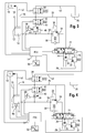
- einen erfindungsgemäßen Hydraulik-Schaltplan mit ständig umfließendem Volumenstrom und regelbarem Druckbegrenzungsventil,
- Fig. 2
- einen erfindungsgemäßen Hydraulik-Schaltplan mit ständig umfließendem Volumenstrom und verstellbarer Drossel,
- Fig. 3
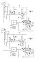
- einen erfindungsgemäßen Hydraulik-Schaltplan mit bei Bedarf fließendem Volumenstrom und regelbarem Druckbegrenzungsventil und
- Fig. 4
- einen erfindungsgemäßen Hydraulik-Schaltplan mit bei Bedarf fließendem Volumenstrom und verstellbarer Drossel,
- Fig. 5
- einen erfindungsgemäßen Hydraulik-Schaltplan gemäß Figur 1 ohne ein erstes Sperrventil,
- Fig. 6
- einen erfindungsgemäßen Hydraulik-Schaltplan gemäß Figur 1 mit einem Rückschlagventil anstelle des Sperrventils,
- Fig. 7
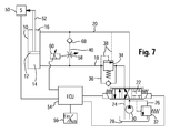
- einen erfindungsgemäßen Hydraulik-Schaltplan gemäß Figur 2 mit einem Rückschlagventil anstelle des Sperrventils,
- Fig. 8
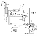
- einen erfindungsgemäßen Hydraulik-Schaltplan mit ständig umfließendem Volumenstrom und regelbarem Druckbegrenzungsventil für einen einfach wirkenden Hydraulikzylinder und
- Fig. 9
- einen erfindungsgemäßen Hydraulik-Schaltplan gemäß Figur 8 für einen Teleskopzylinder.
- Fig. 1
- a hydraulic circuit diagram according to the invention with continuously circulating flow and adjustable pressure relief valve,
- Fig. 2
- a hydraulic circuit diagram according to the invention with constantly flowing volume flow and adjustable throttle,
- Fig. 3
- a hydraulic circuit diagram according to the invention with if necessary flowing flow and adjustable pressure relief valve and
- Fig. 4
- a hydraulic circuit diagram according to the invention with, if necessary, flowing volume flow and adjustable throttle,
- Fig. 5
- 1 a hydraulic circuit diagram according to the invention according to FIG. 1 without a first shut-off valve,
- Fig. 6
- 1 shows a hydraulic circuit diagram according to the invention according to FIG. 1 with a check valve instead of the check valve,
- Fig. 7
- 2 shows a hydraulic circuit diagram according to the invention according to FIG. 2 with a check valve instead of the check valve;
- Fig. 8
- a hydraulic circuit diagram according to the invention with constantly flowing volume flow and adjustable pressure relief valve for a single-acting hydraulic cylinder and
- Fig. 9
- a hydraulic circuit diagram according to the invention according to Figure 8 for a telescopic cylinder.
Figur 1 zeigt einen Hydraulikzylinder 10 mit einem
Hydraulikkolben 12, der zum Heben und Senken eines Auslegers
eines Laderfahrzeugs (beides nicht gezeigt) dient. Der
Hydraulikzylinder 10 weist eine hubseitige Kammer 14 und eine
senkseitige Kammer 16 auf. Die hubseitige Kammer 14 ist über
eine hubseitige Hydraulikleitung 18 und die senkseitige Kammer
16 über eine senkseitige Hydraulikleitung 20 mit einem
elektrisch schaltbaren Steuerventil 22 verbunden.FIG. 1 shows a
Das Steuerventil 22 ist über eine Abflussleitung 24 und über
eine Druckbegrenzungsleitung 26 mit einem Hydrauliköltank 28
verbunden. Eine Hydraulikölpumpe 30 fördert Hydrauliköl über
das Steuerventil 22 in die jeweiligen Hydraulikleitungen 18,
20.The
Das Steuerventil 22 ist in drei Stellungen schaltbar, in eine
Schließstellung, in der kein Durchfluss für beide
Hydraulikleitungen 18, 20 stattfindet, eine Hubstellung, in
der die hubseitige Hydraulikleitung 18 mit Hydrauliköl
versorgt wird, wobei die senkseitige Hydraulikleitung 20
Hydrauliköl an den Hydrauliktank 28 abgibt, und eine
Senkstellung, in der die senkseitige Hydraulikleitung 20 mit
Hydrauliköl versorgt wird, wobei die hubseitige
Hydraulikleitung 18 Hydrauliköl an den Hydrauliktank 28
abgibt.The
Die Druckbegrenzungsleitung 26 enthält ein Druckbegrenzungsventil
32, welches bei Erreichen eines Grenzdrucks öffnet und
einen Durchfluss von der Hydraulikölpumpe 30 zum
Hydrauliköltank 28 ermöglicht. Die Hydraulikölpumpe 30 kann
auf diese Weise auch bei geschlossenem Steuerventil 22
Hydrauliköl fördern. The
Die hubseitige Hydraulikleitung 18 enthält ein Lasthalteventil
34, welches über eine Beipassleitung 36 einen Hydraulikölfluss
in Richtung des Hydraulikzylinders 10 zulässt. Über
Steuerleitungen 38 wird das Lasthalteventil bei Überlast in
Richtung des Hydrauliköltanks 28 geöffnet, so dass ein
Hydraulikölfluss zum Hydrauliköltank 28 stattfinden kann.The lift-side
Zwischen der hubseitigen und der senkseitigen Hydraulikleitung
18, 20 ist eine Verbindungsleitung 40 angeordnet, welche ein
elektrisch schaltbares erstes Sperrventil 42 enthält. Das
erste Sperrventil enthält eine Sperrstellung, in der in beide
Richtungen kein Durchfluss stattfindet und eine
Öffnungsstellung, in der in beide Richtungen ein Durchfluss
ermöglicht wird. Des Weiteren enthält die Verbindungsleitung
40 ein regelbares Druckbegrenzungsventil 44, welches über eine
Steuerleitung 46 in Richtung der senkseitigen Hydraulikleitung
20 öffnet. Der Steuerdruck zum Öffnen des
Druckbegrenzungsventils kann über einen Regler 48 geregelt
werden.Between the lift side and the lower side
Ferner ist ein Positionssensor 50 mit einer Kolbenstange 52
des Hydraulikzylinders 10 verbunden und liefert ein die
Position des Hydraulikkolbens 12 wiedergebendes Sensorsignal
an eine Steuereinheit 54. Die Steuereinheit 54 ist mit einer
Schaltvorrichtung 56 verbunden, über welche die Steuereinheit
54 und damit die hydraulische Federung aktiviert werden kann.Furthermore, a
Gemäß Figur 1 wird die hydraulische aktive Federung mit einem
ständig strömenden Volumenstrom realisiert. Dazu wird die
Steuereinheit 54 über die Schaltvorrichtung 56 aktiviert,
wobei die Steuereinheit 54 das erste Sperrventil 42 öffnet und
das Steuerventil 22 in die Hubstellung schaltet. Die
Hydraulikölpumpe 30 fördert das Hydrauliköl über das
Steuerventil 22 und über das Lasthalteventil 34 zum
Hydraulikzylinder 10 des Auslegers. Dort baut sich ein
bestimmter Druck auf, der mittels des regelbaren
Druckbegrenzungsventils 44 eingestellt wird. Sobald sich ein
Druckgleichgewicht eingestellt hat, nimmt der Hydraulikkolben
12 eine bestimmte Stellung ein, wobei überschüssiges, von der
Hydraulikölpumpe gefördertes Hydrauliköl über das
Druckbegrenzungsventil 44 und über das erste Sperrventil 42
zum Hydrauliktank strömt.According to Figure 1, the hydraulic active suspension with a
constantly flowing volume flow realized. This is the
Das grundlegende Wirkprinzip besteht darin, dass der Druck auf
der Hubseite des Hydraulikzylinders 10 dadurch kontrolliert
wird, dass ein bestimmter Zufluss von Hydrauliköl zur Hubseite
kontrolliert zum Hydrauliktank 28 wieder abfließen kann. Der
Druck wird derart erzeugt, dass das Hydrauliköl nur gegen
einen bestimmten Widerstand, welcher durch das
Druckbegrenzungsventil 44 vorgegeben wird, zum Hydrauliktank
28 strömen kann, wobei dieser Druck so hoch ist, dass er eine
Last, die auf den Hydraulikzylinder 10 einwirkt,
entgegenwirken kann.The basic operating principle is that the pressure on
the stroke side of the
Damit der Volumenstrom strömen kann, muss das Sperrventil 42
in seine offene Stellung geschaltet sein. Ist dieses nicht der
Fall, baut sich auf der Hubseite des Hydraulikzylinders 10 und
somit in der hubseitigen Kammer 14 ein Druck auf, der den
Kolben ausfahren und somit den Ausleger ansteigen lässt.
Über das regelbare Druckbegrenzungsventil 44 wird der Druck,
der auf der Hubseite des Hydraulikzylinders 10 herrschen soll,
je nach Bedarf durch die Steuereinheit 54 eingestellt. So that the volume flow can flow, the
About the controllable
Die Position des Auslegers bzw. die Stellung der Kolbenstange
52 bzw. des Hydraulikkolbens 12 wird über den Positionssensor
50 ständig gemessen und dient als Regelgröße (Istwert) zum
Einstellen des Druckes auf der Hubseite des Hydraulikzylinders
10. Gemessen werden kann diese Position auf unterschiedliche
Art und Weise. Eine Möglichkeit zeigt Figur 1, in der die
Position der Kolbenstange 52 abgegriffen wird. Ebenfalls
geeignet wäre auch der Hubwinkel des Auslegers.The position of the boom or the position of the
Bei Aktivierung der Steuereinheit 54 wird die Regelung
aktiviert und die Ursprungsposition des Auslegers als
einzuhaltende Führungsgröße (Sollwert) festgehalten. Die
Steuereinheit 54 ermittelt über einen integrierten Prozessor
(nicht gezeigt) aus der Führungsgröße und der aktuellen,
gemessenen Regelgröße (Istwert) die Abweichung
(Regeldifferenz) voneinander, um auf dieser Grundlage die
Verstellung des Druckbegrenzungsventils 54 mittels einer
Stellgröße vorzunehmen.Upon activation of the
Stellt die Steuereinheit fest, dass der Ausleger zu tief
abgesunken ist, wird das Druckbegrenzungsventil 54 auf einen
höheren Wert eingestellt, so dass sich der Druck auf der
Hubseite des Hydraulikzylinders 10 erhöht und der
Hydraulikkolben 12 ausgefahren wird.If the control unit detects that the boom is too low
has dropped, the
Stellt die Steuereinheit 54 fest, dass der Ausleger zu hoch
angehoben wurde, wird das Druckbegrenzungsventil 54 auf einen
geringeren Wert heruntergeregelt, so dass sich der Druck auf
der Hubseite des Hydraulikzylinders verringert und der
Hydraulikzylinder eingefahren wird. If the
Kommt es beispielsweise aufgrund von Fahrbahnunebenheiten zu
Beschleunigungen (Stöße und Schwingungen), die auf das
Fahrwerk einwirken, werden diese Beschleunigungen aufgrund der
Massenträgheit auf den Ausleger übertragen. Die Beschleunigung
erzeugt durch die Masse des Auslegers eine Kraft, die sich als
Störgröße auf den Hydraulikzylinder 10 überträgt und somit das
Hydrauliköl auf der Hubseite des Hydraulikzylinders 10
verdrängt oder entlastet.Does it happen, for example, due to road bumps
Accelerations (shocks and vibrations), which on the
Suspension, these accelerations are due to the
Mass inertia transferred to the boom. The acceleration
generated by the mass of the boom, a force that turns out to be
Disturbance on the
Bei einem Stoß, der den Hydraulikkolben 12 einfahren lässt,
wird das Öl aus der Hubseite des Hydraulikzylinders 10 durch
den Hydraulikkolben 12 verdrängt und fließt über das
Druckbegrenzungsventil 44 ab. Aufgrund des verdrängten
Hydraulikölvolumens sinkt der Ausleger ab, was wiederum als
Regeldifferenz von der Steuereinheit 54 erkannt wird,
woraufhin die Steuereinheit den Öffnungsdruck des
Druckbegrenzungsventils 44 erhöht, indem die Steuereinheit 54
die Stellgröße gemäß der Regeldifferenz bestimmt. Aufgrund der
Erhöhung des Öffnungsdruckes und des ständig von Steuerventil
22 strömenden Volumenstroms wird der Ausleger wieder
angehoben, bis die Regeldifferenz sich wieder zu Null oder auf
einen voreinstellbaren Schwellwert verringert hat.In a shock, which can retract the
Bei einem Stoß, der den Hydraulikkolben 12 ausfahren lässt,
wird das Hydrauliköl auf der Hubseite des Hydraulikzylinders
10 durch die Bewegung des Hydraulikkolbens 12 entlastet und
eine Volumenvergrößerung der hubseitigen Kammer 14 tritt ein.
Der ständig fließende Volumenstrom von Steuerventil 22 füllt
diese Volumenvergrößerung auf, so dass der Hydraulikzylinder
10 ausfahren kann, ohne dass die Gefahr der Erzeugung eines
Vakuums eintritt. Gleichzeitig wird eine Regeldifferenz vom
der Steuereinheit 54 erkannt, woraufhin die Steuereinheit 54
den Öffnungsdruck des Druckbegrenzungsventils 44 verringert,
indem die Steuereinheit 54 die entsprechende Stellgröße gemäß
der Regeldifferenz bestimmt. Aufgrund der Verringerung des
Öffnungsdruckes fließt Hydrauliköl von der Hubseite des
Hydraulikzylinders 10 über das Druckbegrenzungsventil 44 ab
und der Ausleger senkt sich ab, bis die Regeldifferenz sich
wieder zu Null oder auf einen voreinstellbaren Schwellwert
verringert hat.In a shock, which can extend the
Es ist möglich, dass zur Beschleunigung oder Verlangsamung der
Verringerung der Regeldifferenz, das Steuerventil 22 in seinem
Öffnungsquerschnitt zusätzlich je nach aktuellem Bedarf
variabel verändert wird, so dass mehr Volumenstrom zum
Hydraulikzylinder 10 fließen kann. Im Extremfall wäre durch
eine Senkstellung auch eine Umkehr der Volumenstromfließrichtung
denkbar, um den Hydraulikkolben 12 schneller
einfahren zu können.It is possible that to speed up or slow down the
Reduction of the control difference, the
Die Betätigungsart des Steuerventils 22 kann elektrisch,
pneumatisch oder auf andere Weise erfolgen. Ebenfalls ist
denkbar, dass das regelbare Druckbegrenzungsventil 44
pneumatisch oder hydraulisch und nicht wie in Figur 1
dargestellt elektrisch angesteuert wird. Dieses kann bei hohen
Drücken und/oder hohen Volumenströmen vorteilhaft sein, da
dann sehr hohe Kräfte vom Stellmechanismus aufgebracht werden
müssen.The actuation of the
An Stelle des elektrisch regelbaren Druckbegrenzungsventils 44
kann auch, wie in Figur 2 dargestellt, eine elektrisch
regelbare Drossel 58 eingesetzt werden. Das grundlegende
Wirkprinzip bleibt dadurch jedoch erhalten. Instead of the electrically controllable pressure relief valve 44th
can also, as shown in Figure 2, an electric
Das durch die hubseitige Leitung strömende Hydrauliköl fließt
bei geöffnetem Sperrventil 42 ständig über die Drossel 58 zum
Hydrauliktank 28 hin ab. Gemäß der Drosselgleichung stellt
sich über der Drossel 58 ein bestimmter Druckabfall ein, der
von dem Volumenstrom und dem Öffnungsquerschnitt der Drossel
58 abhängt, so dass auf der Hubseite des Hydraulikzylinders 10
ein bestimmter Staudruck entsteht, der ein Absacken des
Auslegers verhindert.The hydraulic oil flowing through the lift-side pipe flows
with
Die Höhe des Staudruckes kann über den Volumenstrom vom
Steuerventil 22 oder über den regelbaren Öffnungsquerschnitt
der Drossel 58 verändert werden.The height of the back pressure can be determined by the flow rate of the
Die Position des Auslegers wird ebenfalls ständig gemessen und
dient als Regelgröße (Istwert) zum Einstellen des Staudruckes
auf der Hubseite des Hydraulikzylinders 10. Gemessen werden
kann diese Position ebenfalls auf unterschiedliche Art und
Weise. Denkbar wäre, wie in Figur 2 gezeigt, die Position der
Kolbenstange 52 oder auch der Hubwinkel des Auslegers.The position of the boom is also constantly measured and
serves as a controlled variable (actual value) for setting the dynamic pressure
to be measured on the lifting side of the
Wird die Regelung aktiviert, generiert die Steuereinheit 54,
analog zu dem Beispiel aus Figur 1, eine Stellgröße, mit der
der Öffnungsquerschnitt der Drossel 58 über einen
Drosselregler 60 geregelt und/oder eine Veränderung des
Volumenstromes vom Steuerventil 22 hervorgerufen wird.If the control is activated, the
Stellt die Steuereinheit 54 fest, dass der Ausleger zu tief
abgesunken ist, wird der Öffnungsquerschnitt der Drossel 58
auf einen kleineren Wert eingestellt, so dass sich der
Staudruck auf der Hubseite des Hydraulikzylinders 10 erhöht
und der Hydraulikkolben 12 ausgefahren wird. Ebenfalls kann in
diesem Fall entweder nur oder auch gleichzeitig der
Volumenstrom vom Steuerventil 22 erhöht werden, um den
Staudruck zu erhöhen.If the
Stellt die Steuereinheit 54 fest, dass der Ausleger zu hoch
angehoben wurde, wird der Öffnungsquerschnitt der Drossel 58
auf einen höheren Wert eingestellt, so dass sich der Staudruck
auf der Hubseite des Hydraulikzylinders 10 verringert und der
Hydraulikkolben 12 eingefahren wird. Ebenfalls kann in diesem
Fall entweder nur oder auch gleichzeitig der Volumenstrom vom
Steuerventil 22 verringert werden, um den Staudruck zu
verringern.If the
Bei einem Stoß, der den Hydraulikzylinder 10 einfahren lässt,
wird das Hydrauliköl aus der Hubseite des Hydraulikzylinders
10 durch den Hydraulikkolben 12 komprimiert und der Staudruck
vor der Drossel 58 erhöht sich. Durch die Erhöhung des
Staudruckes erhöht sich ebenfalls der Druckabfall über die
Drossel 58, so dass ein höherer Volumenstrom über die Drossel
58 abfließt. Gleichzeitig sinkt der Ausleger ab, was als
Regeldifferenz von der Steuereinheit 54 erkannt wird,
woraufhin die Steuereinheit 54 den Öffnungsquerschnitt der
Drossel 58 verringert, indem die Steuereinheit 54 die
entsprechende Stellgröße gemäß der Regeldifferenz bestimmt.
Aufgrund dieser Verringerung des Öffnungsquerschnitts der
Drossel 58 kommt es zu einer Erhöhung des Staudruckes, wodurch
der Ausleger wieder angehoben wird, bis sich die
Regeldifferenz wieder zu Null oder auf einen voreinstellbaren
Schwellwert verringert hat.In a shock, which can retract the
Bei einem Stoß, der den Hydraulikzylinder 10 ausfahren lässt,
wird das Hydrauliköl auf der Hubseite des Hydraulikzylinders
10 durch die Bewegung des Hydraulikkolbens 12 entlastet und
eine Volumenvergrößerung der hubseitigen Kammer 14 tritt ein.
Der ständig fließende Volumenstrom von Steuerventil 22 füllt
die Volumenvergrößerung auf, so dass der Hydraulikkolben 12
ausfahren kann, ohne dass die Gefahr der Erzeugung eines
Vakuums eintritt. Aufgrund des hinzugekommenen
Hydraulikölvolumens hebt sich der Ausleger an, was wiederum
als Regeldifferenz von der Steuereinheit 54 erkannt wird,
woraufhin die Steuereinheit 54 den Öffnungsquerschnitt der
Drossel 58 vergrößert, indem die Steuereinheit 54 die
Stellgröße entsprechend der Regeldifferenz bestimmt. Aufgrund
dieser Verringerung des Staudruckes fließt mehr Hydrauliköl
von der Hubseite des Hydraulikzylinders 10 über die Drossel 58
ab als Volumenstrom vom Steuerventil 22 nachfließen kann. Der
Ausleger senkt sich ab, bis sich die Regeldifferenz wieder zu
Null oder auf einen voreinstellbaren Schwellwert verringert
hat.In a shock, which can extend the
Hierbei ist es auch denkbar, dass im Extremfall eine Umkehr
der Volumenstromfließrichtung eingestellt wird, um den
Hydraulikkolben 12 schneller einfahren zu können.It is also conceivable that in extreme cases, a reversal
the volume flow direction is adjusted to the
Des Weiteren kann die elektrisch regelbare Drossel 58, sowie
auch das erste Sperrventil 42 oder das Steuerventil 22,
pneumatisch oder hydraulisch angesteuert werden.Furthermore, the electrically
In weiteren Ausbildungsbeispielen, wie in den Figuren 3 und 4
gezeigt ist, ist eine zweite senkseitige Leitung 62
vorgesehen, die von der ersten senkseitigen Leitung 20 zum
Hydrauliktank 28 führt und mit einem zweiten Sperrventil 64
versehen ist, wobei das erste und das zweite Sperrventil 42,
64 baugleich ausgebildet sein können. In further exemplary embodiments, as in FIGS. 3 and 4
is shown, is a second vertical-side line 62nd
provided from the first
Bei den in den Figuren 3 und 4 dargestellten
Ausführungsbeispielen handelt es sich um bedarfsgesteuerte
Federungssysteme, bei denen, im Unterschied zu den in den
Figuren 1 und 2 dargestellten Ausführungsbeispielen, nur bei
Bedarf ein Volumenstrom vom Steuerventil 22 über ein
Lasthalteventil 34 zum Hydraulikzylinder 10 des Auslegers
fließt. Das Steuerventil 22 befindet sich somit in der
geschlossenen Stellung und wird bei Bedarf von der
Steuereinheit 54 in die entsprechenden anderen Stellungen
geschaltet.In the illustrated in Figures 3 and 4
Embodiments are on-demand
Suspension systems in which, unlike those in the
Figures 1 and 2 illustrated embodiments, only at
Requires a volume flow from the
Figur 3 zeigt die bedarfsgesteuerte hydraulische Federung mit
dem elektrisch regelbaren Druckbegrenzungsventil 44, wie es
auch in Figur 1 zu sehen ist.FIG. 3 shows the demand-controlled hydraulic suspension
the electrically controllable
Wird die Regelung durch die Schalteinheit 56 aktiviert, wird
die Ursprungsposition des Auslegers als einzuhaltende
Führungsgröße (Sollwert) festgehalten und die Steuereinheit
bestimmt aus dieser Führungsgröße und der aktuellen,
gemessenen Position (Regelgröße) die Abweichung
(Regeldifferenz) voneinander, um auf dieser Grundlage die
Regelung des Druckbegrenzungsventils 44 durchzuführen und die
Höhe des Volumenstroms von Steuerventil 22 mittels weiterer
Stellgrößen einzustellen.If the control is activated by the switching
Damit sich der Hydraulikkolben 12 des Hydraulikzylinders 10
aufgrund von auf ihn wirkende Störgrößen bewegen kann, müssen
die Sperrventile 42, 64 in ihre offenen Positionen geschaltet
sein.So that the
Über das elektrisch regelbare Druckbegrenzungsventil 44 wird
der Druck, der auf der Hubseite des Hydraulikzylinders 10
wirken soll, je nach Bedarf durch die Steuereinheit 54
geregelt.About the electrically controllable
Stellt die Steuereinheit 54 fest, dass der Ausleger zu tief
abgesunken ist, wird das Druckbegrenzungsventil 44 auf einen
höheren Wert eingestellt und das Steuerventil 22 geöffnet, so
dass sich durch den fließenden Volumenstrom der Druck auf der
Hubseite des Hydraulikzylinders 10 erhöht und der
Hydraulikzylinder 10 ausgefahren wird.If the
Stellt die Steuereinheit 54 fest, dass der Ausleger zu hoch
angehoben wurde, wird das Druckbegrenzungsventil 44 auf einen
geringeren Wert eingestellt, so dass sich der Druck auf der
Hubseite des Hydraulikzylinders 10 verringert und der
Hydraulikkolben 12 eingefahren wird. Das Hydrauliköl, das von
der Hubseite des Hydraulikzylinders 10 dann über das
Druckbegrenzungsventil 44 und das erste Sperrventil 42 zur
Senkseite des Hydraulikzylinders 10 fließt, fließt von dort
über das zweite Sperrventil 64 zum Hydrauliktank 28.If the
Bei einem Stoß, der den Hydraulikkolben 12 einfahren lässt,
wird das Hydrauliköl aus der Hubseite des Hydraulikzylinders
10 durch den Hydraulikkolben 12 verdrängt und fließt über das
Druckbegrenzungsventil 44 und über die Sperrventile 42, 64 ab.
Aufgrund des verdrängten Ölvolumens sinkt der Ausleger ab, was
wiederum als Regeldifferenz von der Steuereinheit 54 erkannt
wird, woraufhin die Steuereinheit 54 den Öffnungsdruck des
Druckbegrenzungsventils 44 erhöht und das Steuerventil 22 in
Hubstellung bringt, so dass ein Volumenstrom zur Hubseite des
Hydraulikzylinders 10 fließt, wobei die Stellgrößen durch die
Steuereinheit 54 gemäß der Regeldifferenz bestimmt werden.
Aufgrund der Erhöhung des Öffnungsdruckes und des vom
Steuerventil 22 fließenden Volumenstroms wird der Ausleger
wieder angehoben, bis sich die Regeldifferenz wieder zu Null
oder auf einen voreinstellbaren Schwellwert verringert hat.In a shock, which can retract the
Es ist in diesem Fall denkbar, dass zur Beschleunigung des
Anhebens das Sperrventil 42 geschlossen wird, so dass kein
Hydrauliköl zum Hydrauliktank 28 von der Hubseite des
Hydraulikzylinders 10 her abfließen kann.It is conceivable in this case that to speed up the
Lifting the
Bei einem Stoß, der den Hydraulikzylinder 10 ausfahren lässt,
wird das Hydrauliköl auf der Hubseite des Hydraulikzylinders
10 durch die Bewegung des Hydraulikkolbens 12 entlastet und
eine Volumenvergrößerung der hubseitigen Kammer 14 tritt ein,
da Hydrauliköl aus der senkseitigen Kammer 16 zum
Hydrauliktank 28 hin verdrängt wird. Dieses Anheben des
Auslegers wird von der Steuereinheit 54 als Regeldifferenz
erkannt und das Steuerventil 22 in Hubstellung gebracht, um
mittels eines Volumenstroms das entstehende Volumen auf der
Hubseite des Hydraulikzylinders 10 zu füllen. Aufgrund des
hinzugekommenen Hydraulikölvolumens bleibt der Ausleger
angehoben, was nach wie vor als Regeldifferenz von der
Steuereinheit 54 erkannt wird, woraufhin die Steuereinheit 54
den Öffnungsdruck des Druckbegrenzungsventils 44 verringert,
indem die Steuereinheit 54 die Stellgröße gemäß der
Regeldifferenz bestimmt. Darüber hinaus schaltet die
Steuereinheit 54 das Steuerventil 22 wieder in
Schließstellung. Aufgrund der Verringerung des Öffnungsdruckes
fließt Hydrauliköl von der Hubseite des Hydraulikzylinders 10
über das Druckbegrenzungsventil 44 ab und der Ausleger senkt
sich ab, bis sich die Regeldifferenz wieder zu Null oder auf
einen voreinstellbaren Schwellwert verringert hat. In a shock, which can extend the
Es ist auch denkbar, dass nach dem Anheben des Auslegers zum
Absenken des Auslegers, um den Hydraulikzylinder schneller
einfahren zu können, eine Umkehr der Volumenstromfließrichtung
erfolgt, indem die Steuereinheit 54 das Steuerventil 22 in
eine Senkstellung schaltet und die Sperrventil 42, 64
schließt.It is also conceivable that after lifting the boom for
Lower the boom to make the hydraulic cylinder faster
to be able to retract, a reversal of the flow direction
takes place by the
Die in den Figuren 1 bis 4 dargestellten Steuerventile 22 und
Sperrventile 42, 64 sind elektrisch schaltbar dargestellt,
können jedoch auch pneumatisch, hydraulisch oder auf eine
andere Weise angesteuert werden.The
Ein weiteres Ausführungsbeispiel ist in Figur 4 dargestellt.
Der Unterschied zu dem vorherigen, in Figur 3 dargestellten
Ausführungsbeispiel besteht darin, dass, wie auch in Figur 2
dargestellt, eine regelbare Drossel 58 an Stelle des
regelbaren Druckbegrenzungsventils 44 eingesetzt wird. Das
grundlegende Wirkprinzip ist jedoch gleich geblieben.
Zusätzlich ist jedoch ein Drucksensor 66 auf der Hubseite des
Hydraulikzylinders 10 angeordnet, der erforderlich ist, um ein
Öffnungssignal für die Sperrventile 42, 64 an die
Steuereinheit 54 abzugeben. Alternativ können auch anders
geartete Beschleunigungsmessvorrichtungen, mit deren Hilfe die
Belastungen auf den Hydraulikzylinder 10 gemessen werden
können, eingesetzt werden.Another embodiment is shown in FIG.
The difference from the previous, shown in Figure 3
Embodiment is that, as in Figure 2
shown, a
Die Messung der Belastung auf den Hydraulikzylinder 10 ist
erforderlich, um zu bestimmen, wann die Sperrventile 42, 64
geöffnet werden müssen, da sonst über die regelbare Drossel 58
das Hydrauliköl von der Hubseite des Hydraulikzylinders 10
abfließen kann und der Ausleger absinken würde. The measurement of the load on the
Sind die beiden Sperrventile 42, 64 geöffnet, stellt sich
gemäß der Drosselgleichung über der Drossel 58 ein bestimmter
Volumenstrom ein, der von der Druckdifferenz vor und hinter
der Drossel 58, dem Öffnungsquerschnitt der Drossel 58 sowie
von der Hydraulikölviskosität abhängt.Are the two
Die Ermittlung einer Stellgröße zum Einstellen des Staudruckes erfolgt analog zum Ausführungsbeispiel gemäß Figur 2.The determination of a manipulated variable for setting the back pressure takes place analogously to the exemplary embodiment according to FIG. 2.
Wird die Regelung aktiviert, wird die Belastung des
Hydraulikzylinders 10 direkt über den Drucksensor 66 oder
alternativer Weise indirekt über einen Beschleunigungssensor
gemessen. Diese Belastung wird zusammen mit der
Ursprungsposition des Auslegers als einzuhaltende
Führungsgröße (Sollwerte) festgehalten.If the control is activated, the load of the
Stellt die Steuereinheit 54 nun eine bestimmte Abweichung der
Hydraulikzylinderbelastung fest, öffnet die Steuereinheit 54
das Steuerventil 22 sowie die beiden Sperrventile 42, 64,
damit ein Volumenstrom fließen kann. Dieser Volumenstrom
erzeugt durch die Drosselung einen derartigen Staudruck auf
der Hubseite des Hydraulikzylinders 10, dass die auf den
Hydraulikzylinder 10 einwirkende Last getragen wird.Does the
Nach dem Öffnen der Ventile bestimmt die Steuereinheit 54 bei
vorhandener Regelabweichung eine oder mehrere Stellgrößen, um
die Verstellung des Öffnungsquerschnitts der Drossel 58
und/oder die Veränderung des Volumenstromes von Steuerventil
22 vorzunehmen.
Stellt die Steuereinheit 54 fest, dass der Ausleger nach dem
Öffnen des Steuerventils 22 und der Sperrventile 42, 64 zu
tief abgesunken ist, wird der Öffnungsquerschnitt der Drossel
58 auf einen kleineren Wert eingestellt, so dass sich der
Staudruck auf der Hubseite des Hydraulikzylinders 10 erhöht
und der Hydraulikkolben 12 ausgefahren wird.After opening the valves, the
If the
Stellt die Steuereinheit 54 fest, dass der Ausleger nach dem
Öffnen des Steuerventils 22 und der Sperrventile 42, 64 zu
hoch angehoben wurde, wird der Öffnungsquerschnitt der Drossel
58 auf einen größeren Wert eingestellt, so dass sich der
Staudruck auf der Hubseite des Hydraulikzylinders 10
verringert und der Hydraulikkolben 12 eingefahren wird. Das
Hydrauliköl, das von der Hubseite des Hydraulikzylinders 10
dann über die Drossel 58 und das Sperrventil 42 zur Senkseite
des Hydraulikzylinders 10 fließt, fließt von dort über das
Sperrventil 64 zum Hydrauliktank 28.If the
Bei einem Stoß, der eine Kraft auf die hubseitige Kammer 14
ausübt, generiert die Steuereinheit 54 auf Grund des
Öffnungssignals durch den Drucksensor 66 eine Stellgröße, die
zur Öffnung des Steuerventils 22 und der Sperrventile 42, 64
führt, so dass der Hydraulikkolben 12 einfahren kann. Das
Hydrauliköl aus der Hubseite des Hydraulikzylinders 10 wird
durch den Hydraulikkolben 12 verdrängt und fließt über die
Drossel 58 und die Sperrventile 42, 64 ab. Aufgrund des
verdrängten Hydraulikölvolumens sinkt der Ausleger ab, was
wiederum als Regeldifferenz vom Regler erkannt wird, woraufhin
die Steuereinheit 54 den Öffnungsquerschnitt der Drossel 58
verringert. Aufgrund der daraus resultierenden Erhöhung des
Staudrucks und des von Steuerventil 22 fließenden
Volumenstroms wird der Ausleger wieder angehoben, bis sich die
Regeldifferenz wieder zu Null oder auf einen voreinstellbaren
Schwellwert verringert hat. In a shock, a force on the stroke-side chamber 14th
exercises the
Es ist in diesem Fall denkbar, dass zur Beschleunigung des
Anhebens das Sperrventil 42 geschlossen wird, so dass kein
Hydrauliköl zum Tank von der Hubseite des Hydraulikzylinders
10 her abfließen kann.It is conceivable in this case that to speed up the
Lifting the
Bei einem Stoß, der eine Kraft auf die senkseitige Kammer 16
ausübt, generiert die Steuereinheit 54 auf Grund des
Öffnungssignals durch den Drucksensor 66 eine Stellgröße, die
zur Öffnung des Steuerventils 22 und der Sperrventile 42, 64
führt, so dass der Hydraulikkolben 12 ausfahren kann. Durch
die Bewegung des Hydraulikkolbens 12 wird das Hydrauliköl auf
der Hubseite des Hydraulikzylinders 10 entlastet und eine
Volumenvergrößerung der hubseitigen Kammer 14 tritt ein, da Öl
aus der senkseitigen Kammer 16 zum Hydrauliktank 28 hin
verdrängt wird. Dieses Anheben des Auslegers wird von der
Steuereinheit 54 als Regeldifferenz erkannt und das
Steuerventil 22 geöffnet, um mittels eines Volumenstroms die
entstehende Volumenvergrößerung auf der Hubseite des
Hydraulikzylinders 10 zu füllen. Aufgrund des hinzugekommenen
Hydraulikölvolumens bleibt der Ausleger angehoben, was nach
wie vor als Regeldifferenz von der Steuereinheit 54 erkannt
wird, woraufhin die Steuereinheit den Öffnungsquerschnitt der
Drossel 58 vergrößert. Darüber hinaus schließt die
Steuereinheit 54 das Steuerventil 22 wieder. Aufgrund der
Vergrößerung des Öffnungsquerschnitts der Drossel 58
Hydrauliköl von der Hubseite des Hydraulikzylinders 10 über
die Drossel 58 ab und der Ausleger senkt sich ab, bis sich die
Regeldifferenz wieder zu Null oder auf einen voreinstellbaren
Schwellwert verringert hat.
Es ist auch denkbar, dass nach dem Anheben des Auslegers zum
beschleunigten Absenken des Auslegers eine Umkehr der
Volumenstromfließrichtung vom Steuerventil 22 erfolgt und die
Sperrventile 42, 64 geschlossen werden.In a shock, which exerts a force on the lower-
It is also conceivable that after lifting the boom for accelerated lowering of the boom, a reversal of the flow direction of flow from the
Figuren 5 bis 7 zeigen vereinfachte Ausführungsbeispiele der Erfindung, die im Wesentlichen den in den Figuren 1 und 2 beschriebenen Ausführungsbeispielen entsprechen, nur dass auf das erste Sperrventil verzichtet wird.FIGS. 5 to 7 show simplified embodiments of the invention Invention, which is essentially the same in FIGS. 1 and 2 correspond to described embodiments, only that the first check valve is omitted.
Figur 5 zeigt die einfachste der dargestellten
Ausführungsbeispiele, indem im Vergleich zu Figur 1 das erste
Sperrventil 42 eingespart wurde. Das in Figur 5 dargestellte
Druckbegrenzungsventil 44 wird dann bei nicht aktivierter
Federung auf einen entsprechend hohen Druckbegrenzungswert
geregelt, so dass die Verbindungsleitung 40 im Wesentlichen
geschlossen ist, ähnlich wie es ein Sperrventil 42 bewirken
würde. Erst bei aktivierter Federung wird das
Druckbegrenzungsventil 44 durch die Steuereinheit 54 auf einen
Regelbereich heruntergeregelt, der im Wesentlichen einem
Regelbereich entsprechend dem Funktionsprinzip bezüglich
Figur 1 entspricht. Im Übrigen wird analog zu dem bereits
beschriebenem Funktionsprinzip für das Ausführungsbeispiel in
Figur 1 verfahren.Figure 5 shows the simplest of the illustrated
Embodiments, in comparison to Figure 1, the
Um eine leckagefreie Abdichtung bei dem in Figur 5
dargestellten Ausführungsbeispiel in Richtung der hubseitigen
Kammer 14 zu gewährleisten, kann vorzugsweise ein
Rückschlagventil 68 eingesetzt werden, wie in Figur 6
dargestellt ist.To a leak-free sealing in the in FIG. 5
illustrated embodiment in the direction of the
Ein weiteres Ausführungsbeispiel ist in Figur 7 dargestellt,
in der im Vergleich zu Figur 2 das erste Sperrventil 42 durch
ein Rückschlagventil 68 ersetzt wurde. Dieses
Ausführungsbeispiel stellt im Vergleich zum
Ausführungsbeispiel gemäß Figur 2 eine Variante dar, mit der
Schaltvorgänge für das erste Sperrventil 42 eingespart werden
können. Die in Figur 7 dargestellte Drossel 58 wird dann bei
nicht aktivierter Federung auf einen entsprechend kleinen,
einen hohen Rückstaudruck erzeugenden, Durchlassquerschnitt
geregelt bzw. entsprechend geschlossen, so dass der
Durchlassquerschnitt der Drossel im Wesentlichen Null beträgt
und die Verbindungsleitung 40 im Wesentlichen geschlossen ist,
ähnlich wie es ein Sperrventil 42 bewirken würde. Erst bei
aktivierter Federung wird die Drossel 58 durch die
Steuereinheit 54 auf einen Regelbereich mit größerem, einen
niedrigeren Rückstaudruck erzeugenden, Durchlassquerschnitt
geregelt bzw. entsprechend geöffnet, wobei der Regelbereich im
Wesentlichen einem Regelbereich entsprechend dem
Funktionsprinzip bezüglich Figur 2 entspricht. Im Übrigen wird
analog zu dem bereits beschriebenem Funktionsprinzip für das
Ausführungsbeispiel in Figur 2 verfahren. Das Rückschlagventil
68 ist hierbei notwendig, um einen Zufluss in Richtung der
hubseitigen Kammer 14 durch die Verbindungsleitung 40 bei
aktivierter Federung zu vermeiden, da eine Drossel 58 oder
Blende in beide Richtungen durchlässig ist. Des Weiteren
können an der Drossel 58 bei deaktivierter Federung auch
Leckagen in Richtung der hubseitigen Kammer 14 eintreten, die
durch das Rückschlagventil 68 vermieden werden können. Das
Rückschlagventil 68 trägt somit auch zu einer einwandfreien
Funktion des Lasthalteventils 34 bei. Bei einer hydraulischen
Federung ohne Lasthalteventil 34 könnte auf das
Rückschlagventil 68 verzichtet werden, da dann immer
Hydrauliköl von der hubseitigen Kammer abfließen kann. A further embodiment is shown in FIG. 7,
in the comparison to Figure 2, the
Die Figuren 8 und 9 zeigen Ausführungsbeispiele für
einfachwirkende Hubzylinder 10. In Figur 8 ist zu erkennen,
dass es sich im Wesentlichen um die Hydraulikschaltung aus
Figur 1 handelt. Da hier ein einfachwirkender Hydraulikzylinder
10 eingesetzt wird, entfällt die Hydraulikleitung 20, so dass
die Verbindungsleitung 40 nun die hubseitige Kammer 14 des
Hydraulikzylinders 10 mit einem Steuerventil 72 bzw. über das
Steuerventil 72 mit dem Hydrauliköltank 28 verbindet. Das
Steuerventil 72 ist dabei derart ausgebildet, dass es in der
Senkstellung die Verbindungsleitung 40 mit der Hydraulikölpumpe
30 und die hubseitige Hydraulikleitung 18 mit dem
Hydrauliköltank 28 verbindet. Zum Absenken des
Hydraulikzylinders 10 ist hinter der Verbindung zur
Steuerleitung 38 in der Verbindungsleitung 40 ein
Rückschlagventil 70 vorgesehen. Erst durch das Rückschlagventil
70 kann der Hydraulikzylinder 10 abgesenkt werden. Das
Steuerventil 72 wird dazu in Senkstellung gebracht, wodurch die
Hydraulikölpumpe 30 aufgrund des in Pumpenförderrichtung
schließenden Rückschlagventils 70 einen Öffnungsdruck in der
Steuerleitung 38 erzeugt, so dass das Lasthalteventil 34
geöffnet und das Hydrauliköl aus der Kammer 14 durch die
hubseitige Hydraulikleitung 18 in den Hydrauliköltank 28
abfließen kann. Des Weiteren ist das Sperrventil 42 an die
Ausgestaltung mit einem einfachwirkenden Hubzylinder 10
angepasst, da hier nur ein Hydraulikölfluss in eine Richtung zu
erwarten ist. Analog hierzu können die Änderungen auch in
Verbindung mit den in den Figuren 2 und 5 bis 7 dargestellten
Hydraulikschaltungen vorgenommen werden, so dass der Einsatz
eines einfachwirkenden Hydraulikzylinders 10 in den in den
Figuren 2 und 5 bis 7 dargestellten Ausführungsbeispielen
ebenfalls möglich ist. Figures 8 and 9 show embodiments for
single-acting
Beispielhaft soll im Folgenden anhand der in den Figuren 8 und
9 dargestellten Ausführungsbeispiele, die Funktionsweise einer
Federung für einen einfachwirkenden Hydraulikzylinder 10
beschrieben werden. Im Unterschied zu Figur 8 ist in Figur 9
ein Teleskopzylinder als Hydraulikzylinder 10 angeordnet. Die
Funktionsweise der Federung wird davon jedoch nicht
beeinflusst. Anhand Figur 9 soll lediglich gezeigt werden, dass
auch teleskopartig arbeitende Hydraulikzylinder 10 einsetzbar
sind.By way of example, the following will be described with reference to FIGS. 8 and
9 illustrated embodiments, the operation of a
Suspension for a single-acting
Gemäß der Figuren 8 und 9 kann die hydraulische aktive
Federung für einen einseitig wirkenden Hydraulikzylinder 10
sowohl mit einem ständig strömenden Volumenstrom als auch mit
einem bedarfsgesteuerten Volumenstrom realisiert werden. Bei
einem ständig strömenden Volumenstrom wird die Steuereinheit
54 über die Schaltvorrichtung 56 aktiviert, wobei die
Steuereinheit 54 das Sperrventil 42 öffnet und das
Steuerventil 72 in die Hubstellung schaltet, in der die
Hydraulikölpumpe 30 mit der hubseitigen Hydraulikleitung 18
verbunden wird. Die Hydraulikölpumpe 30 fördert das
Hydrauliköl über das Steuerventil 72 und über das
Lasthalteventil 34 zum Hydraulikzylinder 10 des Auslegers.
Dort baut sich ein bestimmter Druck auf, der mittels des
regelbaren Druckbegrenzungsventils 44 eingestellt wird. Sobald
sich ein Druckgleichgewicht eingestellt hat, nimmt der
Hydraulikkolben 12 eine bestimmte Stellung ein, wobei
überschüssiges, von der Hydraulikölpumpe 30 gefördertes
Hydrauliköl in der Verbindungsleitung 40 über das
Druckbegrenzungsventil 44 und über das erste Sperrventil 42
sowie über das Rückschlagventil 70 zum Hydrauliktank 28
strömt. Kommt es nun bei aktivierter Federung (Sperrventil 42
ist geöffnet) zum Einfedern des Hydraulikkolbens 12, erzeugt
die Steuereinheit 54 aufgrund des Signals des Positionssensors
50 ein Steuersignal für das Druckbegrenzungsventil 44, welches
daraufhin den Druck in der hubseitigen Hydraulikleitung 18
ansteigen lässt, bis der Hydraulikkolben 12 wieder seine
Ausgangsstellung eingenommen hat.According to the figures 8 and 9, the hydraulic active
Suspension for a single-acting
Die grundlegende Wirkungsweise entspricht demnach auch bei
einem einfach wirkenden Hydraulikzylinder 10, ob konventionell
oder als Teleskopzylinder ausgebildet, dem in Figur 1
beschriebenem Prinzip, so dass der Druck in der hubseitigen
Kammer 14 des einfachwirkenden Hydraulikzylinders 10 dadurch
kontrolliert wird, dass ein bestimmter Zufluss von Hydrauliköl
zur Hubseite (zur Kammer 14) kontrolliert zum Hydrauliktank 28
über die Verbindungsleitung 40 abfließen kann. Für eine
weitere Beschreibung der Wirkungsweise, insbesondere bei
Auftreten von Stößen sei hiermit auf vorangegangene
Ausführungen, insbesondere zu Figur 1 verwiesen.The basic mode of action therefore also corresponds to
a single-acting
Bei einer aktiven Federung mit bedarfsgesteuertem Volumenstrom
wird das Steuerventil 72 nach Heben oder Senken des
Hydraulikzylinders 10 (über die Hub- bzw. Senkstellung des
Steuerventils 72) in seine Mittelstellung geschaltet, in der
sowohl die Hydraulikleitung 18 als auch die Verbindungsleitung
40 mit dem Hydrauliköltank 28 verbunden werden. In dieser
Stellung fließt von der Hydraulikölpumpe 30 her kein
Hydrauliköl durch die Leitungen 18 und 40. Kommt es nun bei
aktivierter Federung (Sperrventil 42 ist geöffnet)
beispielsweise durch Stöße zu einer Druckerhöhung in der
hubseitigen Kammer 14, die mit einem Absinken bzw. Einfedern
des Hydraulkkolbens 12 verbunden ist, so wird dies durch den
Positionssensor 50 erfasst. Die Steuereinheit 54 registriert
die Änderung und erzeugt ein Steuersignal, durch welches das
Steuerventil 72 in seine Hubstellung geschaltet wird. Es folgt
das erneute Anheben des Hydraulikkolbens 10, bis die
Ausgangsstellung des Hydraulikkolbens 10 wieder erreicht wird.
Sobald die Ausgangsstellung erreicht ist, schaltet die
Steuereinheit 54 das Steuerventil 72 wieder in die
Mittelstellung.With an active suspension with demand-controlled volume flow
is the
Auch wenn die Erfindung lediglich anhand einiger Ausführungsbeispiele beschrieben wurde, erschließen sich für den Fachmann im Lichte der vorstehenden Beschreibung sowie der Zeichnung viele verschiedenartige Alternativen, Modifikationen und Varianten, die unter die vorliegende Erfindung fallen.Although the invention is based only on some Embodiments has been described open up for the expert in the light of the above description and the Drawing many different alternatives, modifications and variants which fall under the present invention.
Claims (13)
Applications Claiming Priority (4)
| Application Number | Priority Date | Filing Date | Title |
|---|---|---|---|
| DE2003130344 DE10330344A1 (en) | 2003-07-05 | 2003-07-05 | Active hydraulic spring, especially for a cantilever arm of a loading vehicle, has a control unit that monitors the position of a cylinder piston using a sensor and controls a regulatable pressure limiting unit accordingly |
| DE10330344 | 2003-07-05 | ||
| DE10343742 | 2003-09-22 | ||
| DE10343742 | 2003-09-22 |
Publications (2)
| Publication Number | Publication Date |
|---|---|
| EP1496009A1 true EP1496009A1 (en) | 2005-01-12 |
| EP1496009B1 EP1496009B1 (en) | 2007-09-05 |
Family
ID=33453881
Family Applications (1)
| Application Number | Title | Priority Date | Filing Date |
|---|---|---|---|
| EP04103115A Not-in-force EP1496009B1 (en) | 2003-07-05 | 2004-07-01 | Hydraulic suspension |
Country Status (5)
| Country | Link |
|---|---|
| US (1) | US6988363B2 (en) |
| EP (1) | EP1496009B1 (en) |
| AT (1) | ATE372296T1 (en) |
| DE (1) | DE502004004847D1 (en) |
| ES (1) | ES2289436T3 (en) |
Cited By (7)
| Publication number | Priority date | Publication date | Assignee | Title |
|---|---|---|---|---|
| EP1754836A2 (en) | 2005-08-19 | 2007-02-21 | Deere & Company | Charger |
| EP1762535A2 (en) | 2005-09-13 | 2007-03-14 | Deere & Company | Loader and method for loader |
| EP1897847A3 (en) * | 2006-09-08 | 2009-06-17 | Deere & Company | Charging device |
| CN110319242A (en) * | 2019-08-05 | 2019-10-11 | 安徽理工大学 | A kind of rotary spool switching mechanism based on bidirectional torsion spring |
| CN112010166A (en) * | 2020-08-26 | 2020-12-01 | 江苏金风科技有限公司 | Blade hoisting tool and hydraulic system thereof |
| CN113007159A (en) * | 2021-02-09 | 2021-06-22 | 中国煤炭科工集团太原研究院有限公司 | Hydraulic tensioning method, hydraulic tensioning device and continuous miner |
| EP4344520A1 (en) * | 2022-09-28 | 2024-04-03 | Deere & Company | Control arrangement for a hydraulic three-point power lift |
Families Citing this family (35)
| Publication number | Priority date | Publication date | Assignee | Title |
|---|---|---|---|---|
| JP2004348650A (en) * | 2003-05-26 | 2004-12-09 | Toshiba Corp | Electronic device |
| US7130721B2 (en) * | 2004-10-29 | 2006-10-31 | Caterpillar Inc | Electrohydraulic control system |
| DE102004056418B4 (en) * | 2004-11-23 | 2013-02-28 | Deere & Company | Hydraulic arrangement |
| DE102005021887A1 (en) * | 2005-05-04 | 2006-11-16 | Kässbohrer Geländefahrzeug AG | Method and device for driving stability increase of motor vehicles |
| DE102005038333A1 (en) * | 2005-08-11 | 2007-02-15 | Deere & Company, Moline | Hydraulic arrangement |
| DE102005059240A1 (en) * | 2005-12-12 | 2007-06-14 | Linde Ag | Hydrostatic drive system for controlling load of e.g. ground conveyor, has pump with delivery volume adjusting device that is controllable by control device, and circulating device managing connection of feed pipe of pump with container |
| SE531309C2 (en) * | 2006-01-16 | 2009-02-17 | Volvo Constr Equip Ab | Control system for a working machine and method for controlling a hydraulic cylinder of a working machine |
| JP4353190B2 (en) * | 2006-02-27 | 2009-10-28 | コベルコ建機株式会社 | Hydraulic circuit for construction machinery |
| US7845169B2 (en) * | 2006-10-17 | 2010-12-07 | Caterpillar Inc | Drift compensation control method for a machine |
| US8204653B2 (en) * | 2007-02-21 | 2012-06-19 | Deere & Company | Automated control of boom and attachment for work vehicle |
| JP5064843B2 (en) * | 2007-03-08 | 2012-10-31 | 株式会社小松製作所 | Work equipment pump rotation control system |
| DE102007051857B3 (en) * | 2007-10-30 | 2009-04-23 | Siemens Ag | Control device for position control of a hydraulic cylinder unit with linearization unit |
| US8869520B2 (en) * | 2007-11-21 | 2014-10-28 | Volvo Construction Equipment Ab | Load sensing system, working machine comprising the system, and method for controlling a hydraulic function |
| EP2215311B1 (en) * | 2007-11-21 | 2017-11-01 | Volvo Construction Equipment AB | System, working machine comprising the system, and method of springing an implement of a working machine during transport |
| RU2453658C2 (en) * | 2007-11-21 | 2012-06-20 | Вольво Констракшн Эквипмент Аб | Load-susceptible system, machine incorporating it and method of controlling hydraulic drive |
| EP2697441B1 (en) * | 2011-04-15 | 2017-07-19 | Volvo Construction Equipment AB | Method and device for reducing vibrations in a working machine |
| US9181070B2 (en) * | 2011-05-13 | 2015-11-10 | Kabushiki Kaisha Kobe Seiko Sho | Hydraulic driving apparatus for working machine |
| CN104769320B (en) * | 2012-06-22 | 2018-09-14 | 渐屈线传动有限公司 | Transmission system |
| DE102012106185B3 (en) * | 2012-07-10 | 2013-11-21 | Fsp Fluid Systems Partners Holding Ag | Control arrangement for a hydropneumatic suspension system and hydropneumatic suspension system with such a control arrangement |
| US8833481B2 (en) * | 2012-09-06 | 2014-09-16 | Cnh Industrial America Llc | System for controlling wing tool bars of an agricultural implement having an angle sensor |
| DE102012022030A1 (en) * | 2012-11-12 | 2014-05-15 | Deere & Company | Suspension device for a movably mounted vehicle axle |
| JP5661084B2 (en) * | 2012-11-13 | 2015-01-28 | 株式会社神戸製鋼所 | Hydraulic drive device for work machine |
| JP5661085B2 (en) | 2012-11-13 | 2015-01-28 | 株式会社神戸製鋼所 | Hydraulic drive device for work machine |
| CA2838639C (en) * | 2013-10-23 | 2016-07-19 | Ms Gregson | A method and system for controlling an inclination of a boom carried by a vehicle |
| CN107250737B (en) * | 2015-05-26 | 2019-12-13 | 日立建机株式会社 | Load measuring device for construction machine |
| EP3196623A1 (en) * | 2016-01-25 | 2017-07-26 | Primetals Technologies Germany GmbH | Simple leakage detection in a hydraulic cylinder unit |
| AU2018200354B2 (en) * | 2017-01-17 | 2023-02-23 | The Raymond Corporation | Variable hydraulic pressure relief systems and methods for a material handling vehicle |
| US11357177B2 (en) * | 2017-08-03 | 2022-06-14 | Firefly Automatix, Inc. | Sod harvester hydraulic system for actuating components with precise timing |
| DE102018104586A1 (en) * | 2018-02-28 | 2019-08-29 | Jungheinrich Aktiengesellschaft | Truck with at least one hydraulic mast lifting cylinder |
| US10724209B2 (en) | 2018-04-13 | 2020-07-28 | Deere & Company | Adjustable work implement |
| JP2019199881A (en) * | 2018-05-14 | 2019-11-21 | 株式会社神戸製鋼所 | Hydraulic driving device of working machine |
| WO2020006560A1 (en) * | 2018-06-29 | 2020-01-02 | Kti Hydraulics Inc. | Power units with manual override controls for hydraulic systems |
| DE102019209091A1 (en) * | 2019-06-24 | 2020-12-24 | Festo Se & Co. Kg | Method for operating a fluid system, fluid system and computer program product |
| US11408144B2 (en) | 2019-08-29 | 2022-08-09 | Deere & Company | Variable float and variable blade impact |
| MX2021015616A (en) * | 2020-12-30 | 2022-07-01 | Manitou Italia Srl | Telehandler with facilitated alignment adjustment. |
Citations (4)
| Publication number | Priority date | Publication date | Assignee | Title |
|---|---|---|---|---|
| DE4221943A1 (en) * | 1991-09-04 | 1993-03-18 | Orenstein & Koppel Ag | HYDRAULIC SYSTEM FOR WORKING MACHINES WITH WORKING DEVICES |
| EP0816576A1 (en) * | 1996-06-28 | 1998-01-07 | KABUSHIKI KAISHA KOBE SEIKO SHO also known as Kobe Steel Ltd. | Construction machine |
| DE10006908A1 (en) | 2000-02-16 | 2001-08-23 | Caterpillar Sarl Genf Geneva | Hydraulic cylinder unit for raising and lowering front arm on root harvester has branch pipe leading back to oil tank which is fitted with shut-off valve and pressure-regulating valve |
| DE10046546A1 (en) | 2000-09-19 | 2002-03-28 | Putzmeister Ag | Heavy manipulator for concrete pumping, incorporates damping of mechanical oscillation of handling mast |
Family Cites Families (13)
| Publication number | Priority date | Publication date | Assignee | Title |
|---|---|---|---|---|
| US4643074A (en) * | 1985-03-07 | 1987-02-17 | Vickers, Incorporated | Power transmission |
| DE69014312T2 (en) * | 1989-01-13 | 1995-04-06 | Hitachi Construction Machinery | Hydraulic system for the boom cylinder of a construction machine. |
| JPH0662268B2 (en) * | 1989-04-21 | 1994-08-17 | 株式会社神戸製鋼所 | Displacement restraint device for mobile crane |
| JPH0815998B2 (en) * | 1989-10-14 | 1996-02-21 | 株式会社神戸製鋼所 | Vibration suppressor for wheeled crane |
| DE4105459A1 (en) | 1991-02-21 | 1992-08-27 | Heilmeier & Weinlein | HYDRAULIC CONTROL DEVICE |
| DE4129509C2 (en) | 1991-09-05 | 1994-06-16 | Rexroth Mannesmann Gmbh | Hydraulic control arrangement for construction machines |
| DE4231399A1 (en) | 1992-08-20 | 1994-02-24 | Rexroth Mannesmann Gmbh | Hydraulic control device |
| DE4402580B4 (en) | 1994-01-28 | 2006-12-14 | Linde Ag | Hydraulic drive system |
| JPH0812546A (en) | 1994-06-30 | 1996-01-16 | Toray Dow Corning Silicone Co Ltd | Anti-suntan cosmetic |
| US5666806A (en) * | 1995-07-05 | 1997-09-16 | Caterpillar Inc. | Control system for a hydraulic cylinder and method |
| US5622226A (en) * | 1996-01-29 | 1997-04-22 | Caterpillar Inc. | Method for controlling bounce of a work implement |
| US5890870A (en) * | 1996-09-25 | 1999-04-06 | Case Corporation | Electronic ride control system for off-road vehicles |
| US6422804B1 (en) | 2000-02-18 | 2002-07-23 | Deere & Company | Inertia load dampening hydraulic system |
-
2004
- 2004-07-01 DE DE502004004847T patent/DE502004004847D1/en active Active
- 2004-07-01 AT AT04103115T patent/ATE372296T1/en not_active IP Right Cessation
- 2004-07-01 EP EP04103115A patent/EP1496009B1/en not_active Not-in-force
- 2004-07-01 ES ES04103115T patent/ES2289436T3/en active Active
- 2004-07-02 US US10/884,716 patent/US6988363B2/en not_active Expired - Fee Related
Patent Citations (5)
| Publication number | Priority date | Publication date | Assignee | Title |
|---|---|---|---|---|
| DE4221943A1 (en) * | 1991-09-04 | 1993-03-18 | Orenstein & Koppel Ag | HYDRAULIC SYSTEM FOR WORKING MACHINES WITH WORKING DEVICES |
| DE4221943C2 (en) | 1991-09-04 | 1996-01-25 | Orenstein & Koppel Ag | Hydraulic system for mobile working machines provided with working devices |
| EP0816576A1 (en) * | 1996-06-28 | 1998-01-07 | KABUSHIKI KAISHA KOBE SEIKO SHO also known as Kobe Steel Ltd. | Construction machine |
| DE10006908A1 (en) | 2000-02-16 | 2001-08-23 | Caterpillar Sarl Genf Geneva | Hydraulic cylinder unit for raising and lowering front arm on root harvester has branch pipe leading back to oil tank which is fitted with shut-off valve and pressure-regulating valve |
| DE10046546A1 (en) | 2000-09-19 | 2002-03-28 | Putzmeister Ag | Heavy manipulator for concrete pumping, incorporates damping of mechanical oscillation of handling mast |
Cited By (13)
| Publication number | Priority date | Publication date | Assignee | Title |
|---|---|---|---|---|
| EP1754836A2 (en) | 2005-08-19 | 2007-02-21 | Deere & Company | Charger |
| DE102005039251A1 (en) * | 2005-08-19 | 2007-02-22 | Deere & Company, Moline | charger |
| EP1754836A3 (en) * | 2005-08-19 | 2008-07-16 | Deere & Company | Charger |
| EP1762535A2 (en) | 2005-09-13 | 2007-03-14 | Deere & Company | Loader and method for loader |
| EP1762535A3 (en) * | 2005-09-13 | 2009-01-07 | Deere & Company | Loader and method for loader |
| US7845896B2 (en) | 2006-09-08 | 2010-12-07 | Deere & Company | Loader |
| EP1897847A3 (en) * | 2006-09-08 | 2009-06-17 | Deere & Company | Charging device |
| CN110319242A (en) * | 2019-08-05 | 2019-10-11 | 安徽理工大学 | A kind of rotary spool switching mechanism based on bidirectional torsion spring |
| CN110319242B (en) * | 2019-08-05 | 2024-03-26 | 安徽理工大学 | Rotary valve core switching mechanism based on bidirectional torsion spring |
| CN112010166A (en) * | 2020-08-26 | 2020-12-01 | 江苏金风科技有限公司 | Blade hoisting tool and hydraulic system thereof |
| CN112010166B (en) * | 2020-08-26 | 2022-09-06 | 江苏金风科技有限公司 | Blade hoisting tool and hydraulic system thereof |
| CN113007159A (en) * | 2021-02-09 | 2021-06-22 | 中国煤炭科工集团太原研究院有限公司 | Hydraulic tensioning method, hydraulic tensioning device and continuous miner |
| EP4344520A1 (en) * | 2022-09-28 | 2024-04-03 | Deere & Company | Control arrangement for a hydraulic three-point power lift |
Also Published As
| Publication number | Publication date |
|---|---|
| US20050011190A1 (en) | 2005-01-20 |
| US6988363B2 (en) | 2006-01-24 |
| DE502004004847D1 (en) | 2007-10-18 |
| ATE372296T1 (en) | 2007-09-15 |
| ES2289436T3 (en) | 2008-02-01 |
| EP1496009B1 (en) | 2007-09-05 |
Similar Documents
| Publication | Publication Date | Title |
|---|---|---|
| EP1496009B1 (en) | Hydraulic suspension | |
| EP1450048B1 (en) | Valve arrangement | |
| DE102004056418B4 (en) | Hydraulic arrangement | |
| EP1918136B1 (en) | Suspension system | |
| EP2031256B1 (en) | Lifting device and method for operating a lifting device | |
| EP1766146B1 (en) | Lifting gear valve arrangement | |
| EP1911614B1 (en) | Suspension system | |
| EP1762535B1 (en) | Loader and method for loader | |
| DE102004012382B4 (en) | Hydraulic arrangement | |
| DE102005033154A1 (en) | Hydraulic arrangement | |
| EP1897847B1 (en) | Charging device | |
| EP2064948A2 (en) | Sprayer boom | |
| DE102005038333A1 (en) | Hydraulic arrangement | |
| WO1999029970A1 (en) | Hydraulic control mechanism for a mobile machine tool, especially a wheel loader, for damping longitudinal oscillations | |
| DE3638574A1 (en) | Arrangement for controlling the pressure of a damping cylinder for the suspension of vehicles | |
| DE102005039251A1 (en) | charger | |
| EP1238834A2 (en) | Active vehicle suspension system | |
| EP3914463B1 (en) | Spring-damper system | |
| EP1606988B1 (en) | Ground-surface adaptation device | |
| EP1902874A1 (en) | Active chassis system | |
| EP2952419B1 (en) | Spring damper element for the suspension of vehicle cabs | |
| DE10330344A1 (en) | Active hydraulic spring, especially for a cantilever arm of a loading vehicle, has a control unit that monitors the position of a cylinder piston using a sensor and controls a regulatable pressure limiting unit accordingly | |
| DE2517810A1 (en) | VEHICLE | |
| EP0719947B1 (en) | Load-sensing circuit | |
| DE102004032652A1 (en) | Active hydraulic spring, especially for a cantilever arm of a loading vehicle, has a control unit that monitors the position of a cylinder piston using a sensor and controls a regulatable pressure limiting unit accordingly |
Legal Events
| Date | Code | Title | Description |
|---|---|---|---|
| PUAI | Public reference made under article 153(3) epc to a published international application that has entered the european phase |
Free format text: ORIGINAL CODE: 0009012 |
|
| AK | Designated contracting states |
Kind code of ref document: A1 Designated state(s): AT BE BG CH CY CZ DE DK EE ES FI FR GB GR HU IE IT LI LU MC NL PL PT RO SE SI SK TR |
|
| AX | Request for extension of the european patent |
Extension state: AL HR LT LV MK |
|
| 17P | Request for examination filed |
Effective date: 20050712 |
|
| AKX | Designation fees paid |
Designated state(s): AT BE BG CH CY CZ DE DK EE ES FI FR GB GR HU IE IT LI LU MC NL PL PT RO SE SI SK TR |
|
| GRAP | Despatch of communication of intention to grant a patent |
Free format text: ORIGINAL CODE: EPIDOSNIGR1 |
|
| GRAS | Grant fee paid |
Free format text: ORIGINAL CODE: EPIDOSNIGR3 |
|
| GRAA | (expected) grant |
Free format text: ORIGINAL CODE: 0009210 |
|
| AK | Designated contracting states |
Kind code of ref document: B1 Designated state(s): AT BE BG CH CY CZ DE DK EE ES FI FR GB GR HU IE IT LI LU MC NL PL PT RO SE SI SK TR |
|
| REG | Reference to a national code |
Ref country code: GB Ref legal event code: FG4D Free format text: NOT ENGLISH |
|
| REG | Reference to a national code |
Ref country code: CH Ref legal event code: EP |
|
| REF | Corresponds to: |
Ref document number: 502004004847 Country of ref document: DE Date of ref document: 20071018 Kind code of ref document: P |
|
| REG | Reference to a national code |
Ref country code: IE Ref legal event code: FG4D Free format text: LANGUAGE OF EP DOCUMENT: GERMAN |
|
| GBT | Gb: translation of ep patent filed (gb section 77(6)(a)/1977) |
Effective date: 20071015 |
|
| PG25 | Lapsed in a contracting state [announced via postgrant information from national office to epo] |
Ref country code: FI Free format text: LAPSE BECAUSE OF FAILURE TO SUBMIT A TRANSLATION OF THE DESCRIPTION OR TO PAY THE FEE WITHIN THE PRESCRIBED TIME-LIMIT Effective date: 20070905 |
|
| REG | Reference to a national code |
Ref country code: ES Ref legal event code: FG2A Ref document number: 2289436 Country of ref document: ES Kind code of ref document: T3 |
|
| PG25 | Lapsed in a contracting state [announced via postgrant information from national office to epo] |
Ref country code: PL Free format text: LAPSE BECAUSE OF FAILURE TO SUBMIT A TRANSLATION OF THE DESCRIPTION OR TO PAY THE FEE WITHIN THE PRESCRIBED TIME-LIMIT Effective date: 20070905 |
|
| NLV1 | Nl: lapsed or annulled due to failure to fulfill the requirements of art. 29p and 29m of the patents act | ||
| REG | Reference to a national code |
Ref country code: IE Ref legal event code: FD4D |
|
| PG25 | Lapsed in a contracting state [announced via postgrant information from national office to epo] |
Ref country code: NL Free format text: LAPSE BECAUSE OF FAILURE TO SUBMIT A TRANSLATION OF THE DESCRIPTION OR TO PAY THE FEE WITHIN THE PRESCRIBED TIME-LIMIT Effective date: 20070905 Ref country code: GR Free format text: LAPSE BECAUSE OF FAILURE TO SUBMIT A TRANSLATION OF THE DESCRIPTION OR TO PAY THE FEE WITHIN THE PRESCRIBED TIME-LIMIT Effective date: 20071206 |
|
| PG25 | Lapsed in a contracting state [announced via postgrant information from national office to epo] |
Ref country code: SK Free format text: LAPSE BECAUSE OF FAILURE TO SUBMIT A TRANSLATION OF THE DESCRIPTION OR TO PAY THE FEE WITHIN THE PRESCRIBED TIME-LIMIT Effective date: 20070905 Ref country code: CZ Free format text: LAPSE BECAUSE OF FAILURE TO SUBMIT A TRANSLATION OF THE DESCRIPTION OR TO PAY THE FEE WITHIN THE PRESCRIBED TIME-LIMIT Effective date: 20070905 Ref country code: IE Free format text: LAPSE BECAUSE OF FAILURE TO SUBMIT A TRANSLATION OF THE DESCRIPTION OR TO PAY THE FEE WITHIN THE PRESCRIBED TIME-LIMIT Effective date: 20070905 Ref country code: PT Free format text: LAPSE BECAUSE OF FAILURE TO SUBMIT A TRANSLATION OF THE DESCRIPTION OR TO PAY THE FEE WITHIN THE PRESCRIBED TIME-LIMIT Effective date: 20080206 |
|
| PG25 | Lapsed in a contracting state [announced via postgrant information from national office to epo] |
Ref country code: SE Free format text: LAPSE BECAUSE OF FAILURE TO SUBMIT A TRANSLATION OF THE DESCRIPTION OR TO PAY THE FEE WITHIN THE PRESCRIBED TIME-LIMIT Effective date: 20071205 Ref country code: RO Free format text: LAPSE BECAUSE OF FAILURE TO SUBMIT A TRANSLATION OF THE DESCRIPTION OR TO PAY THE FEE WITHIN THE PRESCRIBED TIME-LIMIT Effective date: 20070905 |
|
| PLBE | No opposition filed within time limit |
Free format text: ORIGINAL CODE: 0009261 |
|
| STAA | Information on the status of an ep patent application or granted ep patent |
Free format text: STATUS: NO OPPOSITION FILED WITHIN TIME LIMIT |
|
| PG25 | Lapsed in a contracting state [announced via postgrant information from national office to epo] |
Ref country code: DK Free format text: LAPSE BECAUSE OF FAILURE TO SUBMIT A TRANSLATION OF THE DESCRIPTION OR TO PAY THE FEE WITHIN THE PRESCRIBED TIME-LIMIT Effective date: 20070905 |
|
| 26N | No opposition filed |
Effective date: 20080606 |
|
| REG | Reference to a national code |
Ref country code: CH Ref legal event code: PL |
|
| PG25 | Lapsed in a contracting state [announced via postgrant information from national office to epo] |
Ref country code: MC Free format text: LAPSE BECAUSE OF NON-PAYMENT OF DUE FEES Effective date: 20080731 |
|
| PG25 | Lapsed in a contracting state [announced via postgrant information from national office to epo] |
Ref country code: EE Free format text: LAPSE BECAUSE OF FAILURE TO SUBMIT A TRANSLATION OF THE DESCRIPTION OR TO PAY THE FEE WITHIN THE PRESCRIBED TIME-LIMIT Effective date: 20070905 |
|
| PG25 | Lapsed in a contracting state [announced via postgrant information from national office to epo] |
Ref country code: SI Free format text: LAPSE BECAUSE OF FAILURE TO SUBMIT A TRANSLATION OF THE DESCRIPTION OR TO PAY THE FEE WITHIN THE PRESCRIBED TIME-LIMIT Effective date: 20070905 Ref country code: LI Free format text: LAPSE BECAUSE OF NON-PAYMENT OF DUE FEES Effective date: 20080731 Ref country code: CH Free format text: LAPSE BECAUSE OF NON-PAYMENT OF DUE FEES Effective date: 20080731 |
|
| PG25 | Lapsed in a contracting state [announced via postgrant information from national office to epo] |
Ref country code: CY Free format text: LAPSE BECAUSE OF FAILURE TO SUBMIT A TRANSLATION OF THE DESCRIPTION OR TO PAY THE FEE WITHIN THE PRESCRIBED TIME-LIMIT Effective date: 20070905 |
|
| PG25 | Lapsed in a contracting state [announced via postgrant information from national office to epo] |
Ref country code: BG Free format text: LAPSE BECAUSE OF FAILURE TO SUBMIT A TRANSLATION OF THE DESCRIPTION OR TO PAY THE FEE WITHIN THE PRESCRIBED TIME-LIMIT Effective date: 20071205 |
|
| PG25 | Lapsed in a contracting state [announced via postgrant information from national office to epo] |
Ref country code: AT Free format text: LAPSE BECAUSE OF NON-PAYMENT OF DUE FEES Effective date: 20080701 |
|
| PG25 | Lapsed in a contracting state [announced via postgrant information from national office to epo] |
Ref country code: LU Free format text: LAPSE BECAUSE OF NON-PAYMENT OF DUE FEES Effective date: 20080701 Ref country code: HU Free format text: LAPSE BECAUSE OF FAILURE TO SUBMIT A TRANSLATION OF THE DESCRIPTION OR TO PAY THE FEE WITHIN THE PRESCRIBED TIME-LIMIT Effective date: 20080306 Ref country code: BE Free format text: LAPSE BECAUSE OF NON-PAYMENT OF DUE FEES Effective date: 20080731 |
|
| PG25 | Lapsed in a contracting state [announced via postgrant information from national office to epo] |
Ref country code: TR Free format text: LAPSE BECAUSE OF FAILURE TO SUBMIT A TRANSLATION OF THE DESCRIPTION OR TO PAY THE FEE WITHIN THE PRESCRIBED TIME-LIMIT Effective date: 20070905 |
|
| PGFP | Annual fee paid to national office [announced via postgrant information from national office to epo] |
Ref country code: DE Payment date: 20140619 Year of fee payment: 11 |
|
| PGFP | Annual fee paid to national office [announced via postgrant information from national office to epo] |
Ref country code: FR Payment date: 20140717 Year of fee payment: 11 Ref country code: ES Payment date: 20140728 Year of fee payment: 11 Ref country code: GB Payment date: 20140729 Year of fee payment: 11 |
|
| PGFP | Annual fee paid to national office [announced via postgrant information from national office to epo] |
Ref country code: IT Payment date: 20140723 Year of fee payment: 11 |
|
| REG | Reference to a national code |
Ref country code: DE Ref legal event code: R119 Ref document number: 502004004847 Country of ref document: DE |
|
| GBPC | Gb: european patent ceased through non-payment of renewal fee |
Effective date: 20150701 |
|
| PG25 | Lapsed in a contracting state [announced via postgrant information from national office to epo] |
Ref country code: GB Free format text: LAPSE BECAUSE OF NON-PAYMENT OF DUE FEES Effective date: 20150701 Ref country code: DE Free format text: LAPSE BECAUSE OF NON-PAYMENT OF DUE FEES Effective date: 20160202 Ref country code: IT Free format text: LAPSE BECAUSE OF NON-PAYMENT OF DUE FEES Effective date: 20150701 |
|
| REG | Reference to a national code |
Ref country code: FR Ref legal event code: ST Effective date: 20160331 |
|
| PG25 | Lapsed in a contracting state [announced via postgrant information from national office to epo] |
Ref country code: FR Free format text: LAPSE BECAUSE OF NON-PAYMENT OF DUE FEES Effective date: 20150731 |
|
| REG | Reference to a national code |
Ref country code: ES Ref legal event code: FD2A Effective date: 20160928 |
|
| PG25 | Lapsed in a contracting state [announced via postgrant information from national office to epo] |
Ref country code: ES Free format text: LAPSE BECAUSE OF NON-PAYMENT OF DUE FEES Effective date: 20150702 |