EP1495959A2 - Shift assist apparatus for a bicycle transmission - Google Patents
Shift assist apparatus for a bicycle transmission Download PDFInfo
- Publication number
- EP1495959A2 EP1495959A2 EP04016006A EP04016006A EP1495959A2 EP 1495959 A2 EP1495959 A2 EP 1495959A2 EP 04016006 A EP04016006 A EP 04016006A EP 04016006 A EP04016006 A EP 04016006A EP 1495959 A2 EP1495959 A2 EP 1495959A2
- Authority
- EP
- European Patent Office
- Prior art keywords
- moving member
- moving
- power transfer
- member engaging
- engaging member
- Prior art date
- Legal status (The legal status is an assumption and is not a legal conclusion. Google has not performed a legal analysis and makes no representation as to the accuracy of the status listed.)
- Granted
Links
- 230000005540 biological transmission Effects 0.000 title claims abstract description 35
- 230000007246 mechanism Effects 0.000 claims abstract description 141
- 230000008878 coupling Effects 0.000 claims abstract description 47
- 238000010168 coupling process Methods 0.000 claims abstract description 47
- 238000005859 coupling reaction Methods 0.000 claims abstract description 47
- 230000033001 locomotion Effects 0.000 claims description 17
- 230000000717 retained effect Effects 0.000 claims 1
- 230000002093 peripheral effect Effects 0.000 description 12
- 230000000295 complement effect Effects 0.000 description 3
- 230000000712 assembly Effects 0.000 description 2
- 238000000429 assembly Methods 0.000 description 2
- 230000008859 change Effects 0.000 description 2
- 230000000694 effects Effects 0.000 description 1
- 230000004048 modification Effects 0.000 description 1
- 238000012986 modification Methods 0.000 description 1
- 230000002028 premature Effects 0.000 description 1
- 230000009467 reduction Effects 0.000 description 1
- 230000008439 repair process Effects 0.000 description 1
- 230000004044 response Effects 0.000 description 1
- 125000006850 spacer group Chemical group 0.000 description 1
- 238000004804 winding Methods 0.000 description 1
Images


Classifications
-
- B—PERFORMING OPERATIONS; TRANSPORTING
- B62—LAND VEHICLES FOR TRAVELLING OTHERWISE THAN ON RAILS
- B62M—RIDER PROPULSION OF WHEELED VEHICLES OR SLEDGES; POWERED PROPULSION OF SLEDGES OR SINGLE-TRACK CYCLES; TRANSMISSIONS SPECIALLY ADAPTED FOR SUCH VEHICLES
- B62M25/00—Actuators for gearing speed-change mechanisms specially adapted for cycles
- B62M25/02—Actuators for gearing speed-change mechanisms specially adapted for cycles with mechanical transmitting systems, e.g. cables, levers
Definitions
- the present invention is directed to bicycles and, more particularly, to inventive features of an apparatus for assisting the operation of a bicycle transmission.
- the assignee's copending application number 10/190,461 discloses an assist mechanism for a bicycle transmission that overcomes such problems. More specifically, that application discloses an assisting apparatus for using power from a moving member to assist the operation of a bicycle transmission, wherein the assisting apparatus comprises a mounting unit; an input transmission member coupled to the mounting unit, wherein the input transmission member moves between at least a first input position and a second input position; and an output transmission member coupled to the mounting unit, wherein the output transmission member moves between at least a first output position and a second output position.
- a moving member engaging member moves between a moving member engaging position and a moving member disengaging position, and a motion transmitting mechanism transmits motion from the moving member engaging member to the output transmission member.
- a switching mechanism moves the moving member engaging member between the moving member engaging position and the moving member disengaging position in response to movement of the input transmission member and the output transmission member.
- an assisting apparatus for using power from a moving member to assist the operation of a bicycle transmission comprises a power transfer mechanism, a drive coupling mechanism, and a position maintaining mechanism.
- the power transfer mechanism moves in one of a first direction and a second direction to upshift the bicycle transmission, and the power transfer mechanism moves in the other one of the first direction and the second direction to downshift the bicycle transmission.
- the drive coupling mechanism couples the power transfer mechanism to the moving member to move the power transfer mechanism in one of the first direction and the second direction, and the position maintaining mechanism prevents the power transfer mechanism from moving in the other one of the first direction and the second direction.
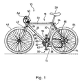
- Fig. 1 is a side view of a bicycle 10 that incorporates a particular embodiment of an apparatus 14 for assisting a change speed operation in a bicycle transmission.
- Bicycle 10 may be any type of bicycle, and in this embodiment bicycle 10 includes a typical frame 18 comprising a top tube 22, a head tube 24, a down tube 26 extending downwardly from head tube 24, a seat tube 30 extending downwardly from top tube 22, a bottom bracket 32 disposed at the junction of down tube 26 and seat tube 30, a pair of seatstays 34 extending rearwardly and downwardly from top tube 22, and a pair of chainstays 38 extending rearwardly from bottom bracket 32.
- a seat in the form of a saddle 39 is mounted to frame 18 at the junction of top tube 22 and seat tube 30.
- a fork 42 is rotatably supported within head tube 24, and a front wheel 46 is rotatably supported to the lower end of fork 42.
- the rotational direction of fork 42 and wheel 46 is controlled by a handlebar 50 in a well known manner.
- a rear wheel 54 having a plurality of coaxially mounted freewheel sprockets (not shown) is rotatably supported at the junction of seatstays 34 and chainstays 38, and a pedal assembly 58 supporting a plurality of front (chainwheel) sprockets 62 is rotatably supported within bottom bracket 32.
- three front sprockets 62 rotate coaxially and integrally with pedal assembly 58.
- a chain 66 engages one of the plurality of front sprockets 62 and one of the plurality of freewheel sprockets mounted to rear wheel 54.
- a front derailleur 70 moves chain 66 from one front sprocket 62 to another, and a rear derailleur 74 moves chain 66 from one freewheel sprocket to another. Both operations are well known.
- front derailleur 70 is controlled by pulling and releasing an output control wire assembly 78 coupled to assist apparatus 14, and assist apparatus 14 is controlled by an electrical cable 82 connected to an electrically operated shift control device 84 mounted to the left side of handlebar 50.
- Shift control device 84 may comprise two electrical switches such as an upshift switch and a downshift switch (not shown), or some other appropriate control device.
- a Bowden-type control cable 86 controls rear derailleur 74, and control cable 86 may be controlled in a conventional manner or by an electrically operated mechanism.
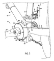
- Fig. 2 is a closer view of shift assist apparatus 14.
- Shift assist apparatus 14 comprises a housing 100 attached to frame 18 by a tubular mounting member 300 (Fig. 4B) that screws into bottom bracket 32. Housing 100 is maintained in a stable and predetermined position relative to frame 18 by a positioning bracket 108 that engages seat tube 30, and an outer cover 112 is attached to housing 100 by screws 116 that screw into corresponding openings 354 (Fig. 5) in housing 100.
- a first derailleur cable 120 of output control wire assembly 78 (Fig. 15) exits shift assist apparatus 14 and extends toward the rear of the bicycle, and a second derailleur cable 124 of output control wire assembly 78 is attached to front derailleur 70.
- a crank arm 128 that forms a part of pedal assembly 58 is mounted to a crank axle 132 that extends through bottom bracket 32 for rotation around an axis X.
- a motor 150 connected to electrical cable 82 (Fig. 1) is provided for operating assist apparatus 14 in a manner described below.
- crank arm 128 includes an elongated crank arm body 220, a crank axle mounting boss 224 at one end having an inner peripheral surface defining a crank axle mounting hole 299 and splines 286 for coupling to complementary splines on axle 132, and a threaded pedal mounting hole 228 on the other end.
- An annular drive ring 270 has a plurality of splines 274 formed on an inner peripheral surface thereof for nonrotatably engaging complementary splines 278 on the laterally innermost outer peripheral surface of crank axle mounting boss 224.
- the outer peripheral surface of drive ring 270 forms a pair of drive projections 290A and 290B, each having an abutment 292A and 292B, respectively, disposed 180° from each other and facing in the forward direction of rotation of crank arm 128.
- abutments 292A and 292B face in the clockwise direction in Fig. 3, and in the counterclockwise direction in Fig. 2.
- Abutments 292A and 292B follow an imaginary straight line extending radially outwardly from the axis of rotation X of pedal assembly 58 and perpendicular to the outer peripheral surface of crank axle mounting boss 224.
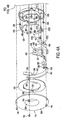
- Figs. 4(A) and 4(B) together comprise an exploded view of shift assist apparatus 14, Fig. 5 is a view showing the interior of housing 100, and Fig. 6 is an oblique view of outer cover 112.
- the tubular mounting member 300 mentioned above has a threaded outer peripheral surface 304 and a flange 308, wherein threaded outer peripheral surface 304 screws into a complementary threaded inner peripheral surface (not shown) in bottom bracket 32, and flange 308 abuts against a mounting surface 310 of housing 100 to secure housing 100 to bottom bracket 32.
- a cartridge bearing 312 is fitted within a bearing seat 316 in housing 100 for rotatably supporting an annular lower pawl mounting member 320, wherein lower pawl mounting member 320 is attached to an annular upper pawl mounting member 324 through screws 328.
- An arcuate pawl control member 340 having a positioning abutment 342, a pawl decoupling wall 344 and a pawl releasing notch 348 is mounted to a peripheral edge of housing 100 through a pair of the screws 116 that extend through outer cover 112, through openings 353 in pawl control member 340 and into a corresponding pair of the openings 354 on the peripheral edge of housing 100.
- housing 100 also has a pawl decoupling wall 357, a pawl decoupling wall 358, a positioning ramp 349, a positioning abutment 350 and a pawl decoupling wall 359 that function in a manner discussed below.
- outer cover 112 includes a plate portion 500 and a cylindrical portion 504 with a cutout 508 (Fig. 6) defining an intermediate position maintaining abutment 509 that function in a manner described below.
- Drive pawl assemblies comprising drive sub-pawls 360, 364 and drive sub-pawls 368, 372 are pivotably mounted to lower pawl mounting member 320 so as to be sandwiched between lower pawl mounting member 320 and upper pawl mounting member 324. More specifically, drive sub-pawl 360 is pivotably mounted to a pivot shaft 376 on drive sub-pawl 364, and pivot shaft 376 is further pivotably mounted to an opening 378 in lower pawl mounting member 320 so that both sub-pawls 360 and 364 are pivotably mounted to lower pawl mounting member 320.
- Drive sub-pawl 360 includes a movable member engaging portion 380 and a pawl control portion 384.
- Movable member engaging portion 380 is provided for engaging one of the abutments 292A or 292B on crank arm 128, and pawl control portion 384 is provided for engaging a pawl control portion 388 on drive sub-pawl 364.
- Drive sub-pawl 360 is biased in the clockwise direction by a spring 389 mounted to upper pawl mounting member 324 through a screw 390. More specifically, a spring arm 391 of spring 389 extends through an opening 393 (Fig. 7(A)) in upper pawl mounting member 324 and contacts movable member engaging portion 380 of drive sub-pawl 360.
- Pawl control portion 384 of drive sub-pawl 360 is biased against the pawl control portion 388 on drive sub-pawl 364, so both drive sub-pawl 360 and drive sub-pawl 364 are biased in the clockwise direction.
- Pawl control portion 388 on drive sub-pawl 364 includes a control pin 392 that functions in a manner described below.
- drive sub-pawl 368 is pivotably mounted to a pivot shaft 400 on drive sub-pawl 372, and pivot shaft 400 is further pivotably mounted to an opening (not shown) in lower pawl mounting member 320 so that both drive sub-pawls 368 and 372 are pivotably mounted to lower pawl mounting member 320.
- Drive sub-pawl 368 includes a movable member engaging portion 404 and a pawl control portion 408. Movable member engaging portion 404 is provided for engaging one of the abutments 292A or 292B on crank arm 128, and pawl control portion 408 is provided for engaging a pawl control portion 412 on drive sub-pawl 372.
- Drive sub-pawl 368 is biased in the clockwise direction by a spring 420 mounted to upper pawl mounting member 324 through a screw 428. More specifically, a spring arm 424 of spring 420 extends through an opening 430 (Fig. 7(A)) in upper pawl mounting member 324 and contacts movable member engaging portion 404 of drive sub-pawl 368. As a result, pawl control portion 408 of drive sub-pawl 368 is biased against the pawl control portion 412 on drive sub-pawl 372, so both drive sub-pawl 368 and drive sub-pawl 372 are biased in the clockwise direction. Pawl control portion 412 on drive sub-pawl 372 includes a control pin 416 that functions in a manner described below.
- Position maintaining pawl assemblies comprising main position maintaining sub-pawls 450, 458 and auxiliary position maintaining sub-pawls 454, 462 are pivotably mounted so as to sandwich upper pawl mounting member 324. More specifically, a pivot shaft 470 is mounted to an opening 471 in lower pawl mounting member 320, pivotably supports auxiliary position maintaining sub-pawl 454 on the right side of upper pawl mounting member 324, extends through an opening 472 in upper pawl mounting member 324, and pivotably supports main position maintaining sub-pawl 450 on the left side of upper pawl mounting member 324.
- Auxiliary position maintaining sub-pawl 454 includes a moving member engaging portion 453 and an intermediate position maintaining portion 452 defining a main position maintaining sub-pawl contact ledge 452a on the bottom thereof.
- Main position maintaining sub-pawl 450 includes a position maintaining tooth 456 and a partial slot 455 that forms an abutment 455a for contacting main position maintaining sub-pawl contact ledge 452a.
- a spring leg 488 of a spring 490 that is mounted to upper pawl mounting member 324 by a screw 491 biases main position maintaining sub-pawl 450 counterclockwise (radially outward).
- Auxiliary position maintaining sub-pawl 454 is biased in a clockwise (radially inward) direction by a spring 474 mounted around pivot shaft 470.
- auxiliary position maintaining sub-pawl 454 ordinarily is held radially outward by the contact between ledge 452a and abutment 455a because the spring force of spring 490 is greater than the spring force of spring 474
- a pivot shaft 480 is mounted to an opening (not shown) in lower pawl mounting member 320, pivotably supports auxiliary position maintaining sub-pawl 462 on the right side of upper pawl mounting member 324, extends through an opening 484 in upper pawl mounting member 324, and pivotably supports main position maintaining sub-pawl 458 on the left side of upper pawl mounting member 324.
- Auxiliary position maintaining sub-pawl 462 includes a moving member engaging portion 464 and an intermediate position maintaining portion 463 defining a main position maintaining sub-pawl contact ledge 463a on the bottom thereof.
- Main position maintaining sub-pawl 458 includes a position maintaining tooth 466 and a partial slot 465 that forms an abutment 465a for contacting main position maintaining sub-pawl contact ledge 463a.
- a spring leg 489 of spring 490 biases main position maintaining sub-pawl 458 counterclockwise (radially outward).
- Auxiliary position maintaining sub-pawl 462 is biased in a clockwise (radially inward) direction by a spring 492 mounted around pivot shaft 480.
- auxiliary position maintaining sub-pawl 462 ordinarily is held radially outward by the contact between ledge 463a and abutment 465a because the spring force of spring 490 is greater than the spring force of spring 492.
- motor 150 includes a drive control link 510 pivotably mounted to a drive control arm 518 which, in turn, is pivotably mounted to a pivot shaft 516.
- Drive control link 510 is coupled to a drive control ring 511 concentrically and rotatably mounted in housing 100 (only a very small section of drive control ring 511 is shown in the drawings).
- Drive control ring 511 has a movable drive control abutment 512 that extends through a drive control opening 513 in housing 100. When drive control abutment 512 is in the position shown in Figs.
- motor 150 can rotate drive control ring 511 in a clockwise direction via drive control link 510 and drive control arm 518 so that drive control abutment 512 moves to the right edge of drive control opening 513 as shown in Fig. 7(D).
- motor 150 can rotate drive control ring 511 counterclockwise via drive control link 510 and drive control arm 518 so that drive control abutment 512 returns to the left edge of drive control opening 513.
- Motor 150 also operates a release control pawl 514 with a release control abutment 517 that extends through an opening 515 during a pawl release operation discussed below.
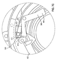
- Fig. 7(A) is a view of the main position maintaining sub-pawls 450 and 458 of the position maintaining mechanism when assist apparatus 14 is in an initial position
- Fig. 7(B) is a view of the auxiliary position maintaining sub-pawls 454 and 462 of the position maintaining mechanism and the drive sub-pawls 360, 364 and 368, 372 of the drive coupling mechanism when shift apparatus 14 is in an inactivated state and in the initial position.
- front derailleur 70 is of the type wherein pulling output control wire assembly 78 causes front derailleur 70 to move chain 66 from a smaller diameter (lower speed) sprocket to a larger diameter (higher speed) sprocket
- FIG. 7(A) represents assist apparatus 14 in a low speed position.
- position maintaining tooth 466 of main position maintaining sub-pawl 458 abuts against positioning abutment 342 of pawl control member 340;
- position maintaining tooth 456 of main position maintaining sub-pawl 450 is in an idle position;
- control pin 416 of drive sub-pawl 372 is held radially inwardly against the biasing force of spring 420 by drive control abutment 512;
- control pin 392 of drive sub-pawl 364 is held radially inwardly against the biasing force of spring 389 by drive control abutment 357 of housing 100.
- This positioning of drive sub pawls 360, 364 and 368, 372 ensure that the moving member engaging portions 380 and 404 of drive sub-pawls 360 and 368, respectively, are held radially inwardly so that neither moving member engaging portion 380 nor moving member engaging portion 404 can contact either of the abutments 292A, 292B on crank arm 128.
- Figs. 7(C) - 7(E) illustrate the operation of drive sub-pawls 360,364 and 368,372 when switching from an inactivated state to an activated state.
- motor 150 moves drive control link 510 and drive control arm 518 so that drive control abutment 512 moves from the position shown in Fig. 7(C) to the right edge of drive control opening 513 as shown in Fig. 7(D).
- drive sub-pawl 372 rotates clockwise, and control pin 416 moves radially outwardly into pawl releasing notch 348 of pawl control member 340 in accordance with the biasing force of spring 420.
- Drive sub-pawl 368 also rotates clockwise as shown in Figs. 7(D) and 7(E), and movable member engaging portion 404 of drive sub-pawl 368 moves radially inwardly. In this position, movable member engaging portion 404 of drive sub-pawl 368 will engage one of the abutments 292A or 292B on crank arm 128 when crank arm 128 is in the proper rotational position. When that happens, the rotational force of crank arm 128 is communicated to lower pawl mounting member 320 and upper pawl mounting member 328 through drive sub-pawl 368. Accordingly, main position maintaining sub-pawls 450 and 458 and drive sub-pawls 360,364 and 368,372 rotate counterclockwise together.
- drive sub-pawl 372 rotates counterclockwise, and moving member engaging portion 404 of drive sub-pawl 368 eventually disengages from the engaged abutment 292A or 292B of crank arm 118.
- control pin 416 resists the radially inward force of arcuate spring 332 as a result of the engaging force between drive sub-pawl 368 and the engaged abutment 292A or 292B, so arcuate spring 332 initially is deformed radially outwardly.
- the spring force and radially inward path of arcuate spring 332 overcome this engaging force, and drive sub-pawl 368 disengages from the engaged abutment 292A or 292B.
- arcuate spring 332 If arcuate spring 332 is weak, then drive sub-pawl 368 will remain engaged with the engaged abutment 292A or 292B longer, and position maintaining tooth 456 of main position maintaining sub-pawl 450 will move further beyond positioning abutment 350, than if arcuate spring 332 were strong.
- output control wire assembly 78 causes front derailleur 70 to move chain 66 temporarily beyond the destination sprocket and then return chain 66 to a position aligned with the destination sprocket.
- This overshift phenomenon is well known and facilitates shifting a chain from a smaller diameter sprocket to a larger diameter sprocket. It should be readily apparent that the amount of overshifting may be adjusted by selecting an appropriate strength of arcuate spring 332.
- control pin 416 of drive sub-pawl 372 which was held radially inwardly by pawl decoupling wall 358, moves to the position radially inwardly of pawl decoupling wall 359 and remains held radially inwardly.
- control pin 392 of drive sub-pawl 364 slides along arcuate spring 332 and is pushed radially inwardly 118 in the same manner discussed above for drive sub-pawl 372.
- position maintaining tooth 466 of main position maintaining sub-pawl 458 slides up positioning ramp 349, across pawl decoupling wall 359, and slightly beyond positioning abutment 350 to produce the overshift effect.
- control pin 392 of drive sub-pawl 364 moves radially inwardly, drive sub-pawl 364 rotates counterclockwise, and moving member engaging portion 380 of drive sub-pawl 364 eventually disengages from the engaged abutment 292A or 292B of crank arm in the same manner discussed above for drive sub-pawl 372.
- lower pawl mounting member 320 and upper pawl mounting member 324 rotate slightly clockwise as a result of the biasing force of the return spring in front derailleur 70.
- control pin 392 of drive sub-pawl 364 moves radially inwardly of pawl decoupling wall 358 as shown in Fig. 9(B), and position maintaining tooth 466 of main position maintaining sub-pawl 458 abuts against positioning abutment 350 as shown in Fig. 9(C).
- Assist apparatus 14, and output control wire assembly 78 is in the high speed position at that time.
- release control abutment 517 extends through opening 515 in housing 100, presses against position maintaining tooth 466 of main position maintaining sub-pawl 458 to rotate it clockwise, and disengages positioning tooth 466 from positioning abutment 350.
- abutment 465a in slot 465 allows main position maintaining sub-pawl contact ledge 463a and hence auxiliary position maintaining sub-pawl 462 to rotate clockwise (radially inward) in accordance with the biasing force of spring 492.
- moving member engaging portion 464 of auxiliary position maintaining sub-pawl 462 is positioned radially inward of cylindrical portion 504 of outer cover 112, and intermediate position maintaining portion 463 of auxiliary position maintaining sub-pawl 462 extends through cutout 508 as shown more specifically in Figs. 11(A) - 11(C).
- Lower pawl mounting member 320 and upper pawl mounting member 324 begin moving clockwise as a result of the disengagement of positioning tooth 466 from positioning abutment 350 and the biasing force of the return spring in front derailleur 70.
- Cutout 508 in outer cover 112 allows main position maintaining sub-pawl 458 and auxiliary position maintaining sub-pawl 462 to rotate slightly clockwise.
- lower pawl mounting member 320, upper pawl mounting member 324 and cable coupling plate 355 also rotate slightly clockwise to release first derailleur cable 120.
- Fig. 1 shows more clearly in Fig.
- moving member engaging portion 464 of auxiliary position maintaining sub-pawl 462 now is in a position to contact one of the abutments 292A or 292B on crank arm 128 as shown in Figs. 11(B) and 11(C). Since moving member engaging portion 464 has an angled surface, auxiliary position maintaining sub-pawl 462 will be pushed radially outwardly by the abutment 292A or 292B, thus disengaging the intermediate position maintaining portion 463 of auxiliary position maintaining sub-pawl 462 from intermediate position maintaining abutment 509 on outer cover 112.
- intermediate position maintaining abutment 509 on outer cover 112 and intermediate position maintaining portion 463 and moving member engaging portion 464 of auxiliary position maintaining sub-pawl 462 allows assist apparatus 14 to delay the rotation of lower pawl mounting plate 320, upper pawl mounting plate 324 and cable coupling plate 355 until one of the abutments 292A or 292B contacts the moving member engaging portion 464 of auxiliary position maintaining sub-pawl 462.
- This allows the timing of the shifting operation to be set very accurately. Such timing can be very important when chain shift facilitating structures are disposed on the sprockets.
- abutments 292A and 292B can be set at a specific angular position relative to the chain shift facilitating structures to enhance the shifting operation.
- auxiliary position maintaining sub-pawl 454 When that happens, auxiliary position maintaining sub-pawl 454 will be pushed radially outwardly by the abutment 292A or 292B, thereby allowing auxiliary position maintaining sub-pawl 454 and main position maintaining sub-pawl 450 to rotate clockwise to the low speed position as shown in Fig. 14. This movement also is communicated to lower pawl mounting member 320, upper pawl mounting member 324, and cable coupling plate 355 so that output control wire assembly is in the low speed position.
- Fig. 15 is a side view of a particular embodiment of bicycle 10 showing an embodiment of a control wire assembly 78 between the assist apparatus 14 and the front derailleur 70 (assist apparatus 14 has been removed in this figure).
- first derailleur cable 120 extends from cable coupling plate 355 in assist apparatus 14 toward the rear of the bicycle.
- first derailleur cable 120 passes around a cable diverter in the form of a roller 600 that is rotatably mounted to the junction of the left side seat stay 34 and chain stay 38. Thereafter, first derailleur cable 120 proceeds toward saddle 39.
- first derailleur cable 120 passes along a winding surface 608 of a cam 612 that is rotatably mounted through a bearing assembly 614 to frame 18 at a junction between top tube 22, seat tube 30 and seat stays 34.
- the terminal portion of first derailleur cable 120 terminates at a cable fastener 616.
- Cam 612 includes a plurality of bias adjusting openings 620 that may be selectively coupled to a biasing spring 624.
- Biasing spring 624 may be used to set the initial position of cam 612 and to provide a biasing force to derailleur 70.
- biasing spring 624 is coupled to seat 39.
- a coupling hook 630 is rotatably coupled to cam 612 through a pivot shaft 634. Coupling hook 630 is coupled to second derailleur cable 124 which, in turn, is fastened to front derailleur 70. This arrangement can reduce the wire stroke by approximately one half.
- the derailleur cable exiting assist apparatus 14 may be fastened directly to front derailleur 70, and the wire stroke may be modified by constructing the derailleur using cams, gear reduction mechanisms, and so on.
- the wire stroke may be adjusted by altering the radial location of the cable coupling opening 356 on cable coupling plate 355.
- annular cable coupling plate 355 may be eliminated.
- lower pawl mounting member 320 may be configured with a cam 700 as shown in Fig. 4(B), and output control wire assembly 78 may be attached to a lever (not shown) that cooperates with cam 700 in a manner disclosed in U.S. Patent No. 6,443,032.
Abstract
Description
- The present invention is directed to bicycles and, more particularly, to inventive features of an apparatus for assisting the operation of a bicycle transmission.
- Various devices have been developed to help reduce the effort needed to operate bicycle transmissions such as derailleurs and internal hub transmissions. Examples of such devices particularly suited to assist the operation of derailleur transmissions are shown in U.S. Patent No. 5,358,451. The devices shown therein for assisting the operation of a rear derailleur employ multiple moving parts that are in constant motion, thus increasing the amount of moving mass as well as the possibility of premature wear on the components. Devices used to assist the operation of a front derailleur employ solenoids that engage cams that rotate with the front pedal assembly, thus requiring precision timing of the solenoid.
- The assignee's copending
application number 10/190,461 discloses an assist mechanism for a bicycle transmission that overcomes such problems. More specifically, that application discloses an assisting apparatus for using power from a moving member to assist the operation of a bicycle transmission, wherein the assisting apparatus comprises a mounting unit; an input transmission member coupled to the mounting unit, wherein the input transmission member moves between at least a first input position and a second input position; and an output transmission member coupled to the mounting unit, wherein the output transmission member moves between at least a first output position and a second output position. A moving member engaging member moves between a moving member engaging position and a moving member disengaging position, and a motion transmitting mechanism transmits motion from the moving member engaging member to the output transmission member. A switching mechanism moves the moving member engaging member between the moving member engaging position and the moving member disengaging position in response to movement of the input transmission member and the output transmission member. - The present invention is directed to inventive features of an apparatus for assisting the operation of a bicycle transmission. In one embodiment, an assisting apparatus for using power from a moving member to assist the operation of a bicycle transmission comprises a power transfer mechanism, a drive coupling mechanism, and a position maintaining mechanism. The power transfer mechanism moves in one of a first direction and a second direction to upshift the bicycle transmission, and the power transfer mechanism moves in the other one of the first direction and the second direction to downshift the bicycle transmission. The drive coupling mechanism couples the power transfer mechanism to the moving member to move the power transfer mechanism in one of the first direction and the second direction, and the position maintaining mechanism prevents the power transfer mechanism from moving in the other one of the first direction and the second direction. Additional inventive features will become apparent from the description below, and such features alone or in combination with the above features may form the basis of further inventions as recited in the claims and their equivalents.
-
- Fig. 1 is a side view of a particular embodiment of a bicycle that incorporates an apparatus according to the invention for assisting a speed change operation in a bicycle transmission;
- Fig. 2 is a closer view of the shift assist apparatus;
- Fig. 3 is an oblique inner view of a particular embodiment of a pedal crank arm used with the shift assist apparatus;
- Figs. 4(A) and 4(B) together comprise an exploded view of the shift assist apparatus;
- Fig. 5 is a view showing the interior of the housing for the shift assist apparatus;
- Fig. 6 is an oblique view of the outer cover of the shift assist apparatus;
- Fig. 7(A) is a view of the main position maintaining sub-pawls of the position maintaining mechanism when the shift assist apparatus is in an initial position;
- Fig. 7(B) is a view of the sub-pawls of the drive coupling mechanism when the shift assist apparatus in an inactivated state and in the initial position;
- Fig. 7(C) is a close-up view of a sub-pawl of the drive coupling mechanism when the shift assist apparatus in the inactivated state and in the initial position;
- Fig. 7(D) is a close-up view of the sub-pawl of the drive coupling mechanism when the shift assist apparatus moves to the activated state;
- Fig. 7(E) is an overall view of the sub-pawls of the drive coupling mechanism when the shift assist apparatus in the activated state;
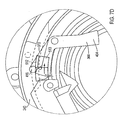
- Fig. 7(F) is a view of the shift assist apparatus just before the drive coupling mechanism disengages from the pedal crank arm;
- Fig. 7(G) is a view of the shift assist apparatus when the drive coupling mechanism disengages from the pedal crank arm;
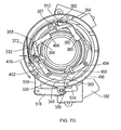
- Fig. 8(A) is a view of the sub-pawls of the drive coupling mechanism when the shift assist apparatus returns to an inactivated state in an intermediate position;
- Fig. 8(B) is a view of the main position maintaining sub-pawls of the position maintaining mechanism when the shift assist apparatus is in the intermediate position;
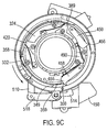
- Fig. 9(A) is a view of the sub-pawls of the drive coupling mechanism when the shift assist apparatus in an activated state and in the intermediate position;
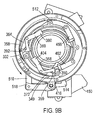
- Fig. 9(B) is a view of the sub-pawls of the drive coupling mechanism when the shift assist apparatus returns to an inactivated state in the final position;
- Fig. 9(C) is a view of the main position maintaining sub-pawls when the shift assist apparatus is in a final position;
- Fig. 10 is a view of the sub-pawls of the position maintaining mechanism when the leftmost main position maintaining sub-pawl is disengaged to allow the power transfer mechanism to move toward the intermediate position;
- Fig. 11(A) is a more detailed view of the initial operation of the sub-pawls of the position maintaining mechanism when returning to a previous position;
- Fig. 11(B) is a more detailed view of the initial operation of the sub-pawls of the position maintaining mechanism just prior to engagement with the moving member;
- Fig. 11(C) is a close-up view of the initial operation of the sub-pawls of the position maintaining mechanism just prior to engagement with the moving member;
- Fig. 12 is a view of the main position maintaining sub-pawls of the position maintaining mechanism after returning to the intermediate position;
- Fig. 13 is a view of the sub-pawls of the position maintaining mechanism when the rightmost main position maintaining sub-pawl is disengaged to move the power transfer mechanism toward the initial position;
- Fig. 14 is a view of the main position maintaining sub-pawls of the position maintaining mechanism after returning to the initial position;
- Fig. 15 is a side view of the bicycle showing a particular embodiment of cabling between the shift assist apparatus and the front derailleur;
- Fig. 16 is a closer view of a particular embodiment of a cable diverter mounted to the rear of the bicycle; and
- Fig. 17 is a closer view of a particular embodiment of a cam mechanism mounted to the upper portion of the bicycle.
-
- Fig. 1 is a side view of a
bicycle 10 that incorporates a particular embodiment of anapparatus 14 for assisting a change speed operation in a bicycle transmission.Bicycle 10 may be any type of bicycle, and in thisembodiment bicycle 10 includes atypical frame 18 comprising atop tube 22, ahead tube 24, adown tube 26 extending downwardly fromhead tube 24, aseat tube 30 extending downwardly fromtop tube 22, abottom bracket 32 disposed at the junction of downtube 26 andseat tube 30, a pair ofseatstays 34 extending rearwardly and downwardly fromtop tube 22, and a pair ofchainstays 38 extending rearwardly frombottom bracket 32. A seat in the form of asaddle 39 is mounted toframe 18 at the junction oftop tube 22 andseat tube 30. Afork 42 is rotatably supported withinhead tube 24, and afront wheel 46 is rotatably supported to the lower end offork 42. The rotational direction offork 42 andwheel 46 is controlled by ahandlebar 50 in a well known manner. Arear wheel 54 having a plurality of coaxially mounted freewheel sprockets (not shown) is rotatably supported at the junction ofseatstays 34 andchainstays 38, and apedal assembly 58 supporting a plurality of front (chainwheel)sprockets 62 is rotatably supported withinbottom bracket 32. In this embodiment, threefront sprockets 62 rotate coaxially and integrally withpedal assembly 58. Achain 66 engages one of the plurality offront sprockets 62 and one of the plurality of freewheel sprockets mounted torear wheel 54. - A
front derailleur 70 moveschain 66 from onefront sprocket 62 to another, and arear derailleur 74 moveschain 66 from one freewheel sprocket to another. Both operations are well known. In this embodiment,front derailleur 70 is controlled by pulling and releasing an outputcontrol wire assembly 78 coupled to assistapparatus 14, and assistapparatus 14 is controlled by anelectrical cable 82 connected to an electrically operatedshift control device 84 mounted to the left side ofhandlebar 50.Shift control device 84 may comprise two electrical switches such as an upshift switch and a downshift switch (not shown), or some other appropriate control device. A Bowden-type control cable 86 controlsrear derailleur 74, andcontrol cable 86 may be controlled in a conventional manner or by an electrically operated mechanism. - Fig. 2 is a closer view of
shift assist apparatus 14.Shift assist apparatus 14 comprises ahousing 100 attached toframe 18 by a tubular mounting member 300 (Fig. 4B) that screws intobottom bracket 32.Housing 100 is maintained in a stable and predetermined position relative toframe 18 by apositioning bracket 108 that engagesseat tube 30, and anouter cover 112 is attached tohousing 100 byscrews 116 that screw into corresponding openings 354 (Fig. 5) inhousing 100. In this embodiment, afirst derailleur cable 120 of output control wire assembly 78 (Fig. 15) exitsshift assist apparatus 14 and extends toward the rear of the bicycle, and asecond derailleur cable 124 of outputcontrol wire assembly 78 is attached tofront derailleur 70. A detailed description of outputcontrol wire assembly 78 will be provided below when discussing Figs. 15-17. Acrank arm 128 that forms a part ofpedal assembly 58 is mounted to a crankaxle 132 that extends throughbottom bracket 32 for rotation around an axis X. Amotor 150 connected to electrical cable 82 (Fig. 1) is provided for operating assistapparatus 14 in a manner described below. - Fig. 3 is an oblique inner view of a particular embodiment of
crank arm 128. Crankarm 128 includes an elongatedcrank arm body 220, a crankaxle mounting boss 224 at one end having an inner peripheral surface defining a crankaxle mounting hole 299 andsplines 286 for coupling to complementary splines onaxle 132, and a threadedpedal mounting hole 228 on the other end. Anannular drive ring 270 has a plurality ofsplines 274 formed on an inner peripheral surface thereof for nonrotatably engagingcomplementary splines 278 on the laterally innermost outer peripheral surface of crankaxle mounting boss 224. The outer peripheral surface ofdrive ring 270 forms a pair ofdrive projections abutment crank arm 128. In other words,abutments pedal assembly 58 and perpendicular to the outer peripheral surface of crankaxle mounting boss 224. - Figs. 4(A) and 4(B) together comprise an exploded view of shift assist
apparatus 14, Fig. 5 is a view showing the interior ofhousing 100, and Fig. 6 is an oblique view ofouter cover 112. Thetubular mounting member 300 mentioned above has a threaded outerperipheral surface 304 and aflange 308, wherein threaded outerperipheral surface 304 screws into a complementary threaded inner peripheral surface (not shown) inbottom bracket 32, andflange 308 abuts against a mountingsurface 310 ofhousing 100 to securehousing 100 tobottom bracket 32. Acartridge bearing 312 is fitted within abearing seat 316 inhousing 100 for rotatably supporting an annular lowerpawl mounting member 320, wherein lowerpawl mounting member 320 is attached to an annular upperpawl mounting member 324 throughscrews 328. Anarcuate spring 332, which functions as a pawl decoupling member or ramp in a manner described below, is mounted to the inner peripheral surface ofhousing 100 through aspacer 335 and ascrew 336 that screws into an opening 338 (Fig. 5) on the peripheral edge ofhousing 100. An arcuatepawl control member 340 having apositioning abutment 342, apawl decoupling wall 344 and apawl releasing notch 348 is mounted to a peripheral edge ofhousing 100 through a pair of thescrews 116 that extend throughouter cover 112, throughopenings 353 inpawl control member 340 and into a corresponding pair of theopenings 354 on the peripheral edge ofhousing 100. As shown more clearly in Fig. 5,housing 100 also has apawl decoupling wall 357, apawl decoupling wall 358, apositioning ramp 349, apositioning abutment 350 and apawl decoupling wall 359 that function in a manner discussed below. - An annular
cable coupling plate 355 having acable coupling opening 356 is mounted to upperpawl mounting member 324 though akey opening 361 so thatcable coupling plate 355 can pull and releasefirst derailleur cable 120 upon movement of upperpawl mounting member 324. As shown in Figs. 4(A) and 6,outer cover 112 includes aplate portion 500 and acylindrical portion 504 with a cutout 508 (Fig. 6) defining an intermediateposition maintaining abutment 509 that function in a manner described below. - Drive pawl assemblies comprising drive sub-pawls 360, 364 and drive sub-pawls 368, 372 are pivotably mounted to lower
pawl mounting member 320 so as to be sandwiched between lowerpawl mounting member 320 and upperpawl mounting member 324. More specifically, drive sub-pawl 360 is pivotably mounted to apivot shaft 376 ondrive sub-pawl 364, andpivot shaft 376 is further pivotably mounted to anopening 378 in lowerpawl mounting member 320 so that bothsub-pawls pawl mounting member 320. Drive sub-pawl 360 includes a movablemember engaging portion 380 and apawl control portion 384. Movablemember engaging portion 380 is provided for engaging one of theabutments arm 128, andpawl control portion 384 is provided for engaging apawl control portion 388 ondrive sub-pawl 364. Drive sub-pawl 360 is biased in the clockwise direction by aspring 389 mounted to upperpawl mounting member 324 through ascrew 390. More specifically, aspring arm 391 ofspring 389 extends through an opening 393 (Fig. 7(A)) in upperpawl mounting member 324 and contacts movablemember engaging portion 380 ofdrive sub-pawl 360. As a result,pawl control portion 384 ofdrive sub-pawl 360 is biased against thepawl control portion 388 ondrive sub-pawl 364, so both drive sub-pawl 360 and drive sub-pawl 364 are biased in the clockwise direction.Pawl control portion 388 ondrive sub-pawl 364 includes acontrol pin 392 that functions in a manner described below. - Similarly, drive sub-pawl 368 is pivotably mounted to a pivot shaft 400 on
drive sub-pawl 372, and pivot shaft 400 is further pivotably mounted to an opening (not shown) in lowerpawl mounting member 320 so that both drive sub-pawls 368 and 372 are pivotably mounted to lowerpawl mounting member 320. Drive sub-pawl 368 includes a movablemember engaging portion 404 and apawl control portion 408. Movablemember engaging portion 404 is provided for engaging one of theabutments arm 128, andpawl control portion 408 is provided for engaging a pawl control portion 412 ondrive sub-pawl 372. Drive sub-pawl 368 is biased in the clockwise direction by aspring 420 mounted to upperpawl mounting member 324 through ascrew 428. More specifically, aspring arm 424 ofspring 420 extends through an opening 430 (Fig. 7(A)) in upperpawl mounting member 324 and contacts movablemember engaging portion 404 ofdrive sub-pawl 368. As a result,pawl control portion 408 ofdrive sub-pawl 368 is biased against the pawl control portion 412 ondrive sub-pawl 372, so both drive sub-pawl 368 and drive sub-pawl 372 are biased in the clockwise direction. Pawl control portion 412 ondrive sub-pawl 372 includes acontrol pin 416 that functions in a manner described below. - Position maintaining pawl assemblies comprising main position maintaining sub-pawls 450, 458 and auxiliary position maintaining sub-pawls 454, 462 are pivotably mounted so as to sandwich upper
pawl mounting member 324. More specifically, apivot shaft 470 is mounted to anopening 471 in lowerpawl mounting member 320, pivotably supports auxiliary position maintaining sub-pawl 454 on the right side of upperpawl mounting member 324, extends through anopening 472 in upperpawl mounting member 324, and pivotably supports main position maintaining sub-pawl 450 on the left side of upperpawl mounting member 324. Auxiliaryposition maintaining sub-pawl 454 includes a movingmember engaging portion 453 and an intermediateposition maintaining portion 452 defining a main position maintaining sub-pawl contact ledge 452a on the bottom thereof. Mainposition maintaining sub-pawl 450 includes aposition maintaining tooth 456 and apartial slot 455 that forms an abutment 455a for contacting main position maintaining sub-pawl contact ledge 452a. Aspring leg 488 of aspring 490 that is mounted to upperpawl mounting member 324 by ascrew 491 biases mainposition maintaining sub-pawl 450 counterclockwise (radially outward). Auxiliaryposition maintaining sub-pawl 454 is biased in a clockwise (radially inward) direction by aspring 474 mounted aroundpivot shaft 470. However, auxiliary position maintaining sub-pawl 454 ordinarily is held radially outward by the contact between ledge 452a and abutment 455a because the spring force ofspring 490 is greater than the spring force ofspring 474. - Similarly, a
pivot shaft 480 is mounted to an opening (not shown) in lowerpawl mounting member 320, pivotably supports auxiliary position maintaining sub-pawl 462 on the right side of upperpawl mounting member 324, extends through an opening 484 in upperpawl mounting member 324, and pivotably supports main position maintaining sub-pawl 458 on the left side of upperpawl mounting member 324. Auxiliaryposition maintaining sub-pawl 462 includes a movingmember engaging portion 464 and an intermediateposition maintaining portion 463 defining a main position maintaining sub-pawl contact ledge 463a on the bottom thereof. Mainposition maintaining sub-pawl 458 includes aposition maintaining tooth 466 and apartial slot 465 that forms an abutment 465a for contacting main position maintaining sub-pawl contact ledge 463a. Aspring leg 489 ofspring 490 biases mainposition maintaining sub-pawl 458 counterclockwise (radially outward). Auxiliaryposition maintaining sub-pawl 462 is biased in a clockwise (radially inward) direction by aspring 492 mounted aroundpivot shaft 480. However, auxiliary position maintaining sub-pawl 462 ordinarily is held radially outward by the contact between ledge 463a and abutment 465a because the spring force ofspring 490 is greater than the spring force ofspring 492. Coupling lowerpawl mounting member 320, upperpawl mounting member 324, main position maintaining sub-pawls 450, 458, auxiliary position maintaining sub-pawls 454, 462 and drive sub-pawls 360, 364, 368, 372 together in this manner allows these components to be removed as a unit fromassist apparatus 14 for ease of assembly and repair. - As shown in Figs. 5, 7(C) and 7(D),
motor 150 includes a drive control link 510 pivotably mounted to adrive control arm 518 which, in turn, is pivotably mounted to apivot shaft 516. Drive control link 510 is coupled to adrive control ring 511 concentrically and rotatably mounted in housing 100 (only a very small section ofdrive control ring 511 is shown in the drawings). Drivecontrol ring 511 has a movabledrive control abutment 512 that extends through a drive control opening 513 inhousing 100. Whendrive control abutment 512 is in the position shown in Figs. 5 and 7(C), then motor 150 can rotatedrive control ring 511 in a clockwise direction viadrive control link 510 and drivecontrol arm 518 so thatdrive control abutment 512 moves to the right edge of drive control opening 513 as shown in Fig. 7(D). Similarly, whendrive control abutment 512 is at the right edge of drive control opening 513,motor 150 can rotatedrive control ring 511 counterclockwise viadrive control link 510 and drivecontrol arm 518 so thatdrive control abutment 512 returns to the left edge of drive control opening 513.Motor 150 also operates arelease control pawl 514 with arelease control abutment 517 that extends through anopening 515 during a pawl release operation discussed below. - Fig. 7(A) is a view of the main position maintaining sub-pawls 450 and 458 of the position maintaining mechanism when assist
apparatus 14 is in an initial position, and Fig. 7(B) is a view of the auxiliary position maintaining sub-pawls 454 and 462 of the position maintaining mechanism and thedrive sub-pawls shift apparatus 14 is in an inactivated state and in the initial position. Iffront derailleur 70 is of the type wherein pulling outputcontrol wire assembly 78 causesfront derailleur 70 to movechain 66 from a smaller diameter (lower speed) sprocket to a larger diameter (higher speed) sprocket, then Fig. 7(A) represents assistapparatus 14 in a low speed position. In this position,position maintaining tooth 466 of mainposition maintaining sub-pawl 458 abuts againstpositioning abutment 342 ofpawl control member 340;position maintaining tooth 456 of mainposition maintaining sub-pawl 450 is in an idle position;control pin 416 ofdrive sub-pawl 372 is held radially inwardly against the biasing force ofspring 420 bydrive control abutment 512; andcontrol pin 392 ofdrive sub-pawl 364 is held radially inwardly against the biasing force ofspring 389 bydrive control abutment 357 ofhousing 100. This positioning ofdrive sub pawls member engaging portions member engaging portion 380 nor movingmember engaging portion 404 can contact either of theabutments arm 128. - Figs. 7(C) - 7(E) illustrate the operation of drive sub-pawls 360,364 and 368,372 when switching from an inactivated state to an activated state. When the rider provides an upshift command using
shift control device 84, then motor 150 moves drivecontrol link 510 and drivecontrol arm 518 so thatdrive control abutment 512 moves from the position shown in Fig. 7(C) to the right edge of drive control opening 513 as shown in Fig. 7(D). At that time, drive sub-pawl 372 rotates clockwise, andcontrol pin 416 moves radially outwardly intopawl releasing notch 348 ofpawl control member 340 in accordance with the biasing force ofspring 420. Drive sub-pawl 368 also rotates clockwise as shown in Figs. 7(D) and 7(E), and movablemember engaging portion 404 ofdrive sub-pawl 368 moves radially inwardly. In this position, movablemember engaging portion 404 ofdrive sub-pawl 368 will engage one of theabutments arm 128 when crankarm 128 is in the proper rotational position. When that happens, the rotational force ofcrank arm 128 is communicated to lowerpawl mounting member 320 and upperpawl mounting member 328 throughdrive sub-pawl 368. Accordingly, main position maintaining sub-pawls 450 and 458 and drive sub-pawls 360,364 and 368,372 rotate counterclockwise together. - As lower
pawl mounting member 320 and upperpawl mounting member 324 rotate counterclockwise,position maintaining tooth 456 of main position maintaining sub-pawl 450 slides uppositioning ramp 349, acrosspawl decoupling wall 359, and slightly beyond positioningabutment 350 as shown in Fig. 7(F).Control pin 392 ofdrive sub-pawl 364, which was held radially inwardly by pawldecoupling wall 357, moves to a position beneathdrive control abutment 512 and remains held radially inwardly. At the same time,control pin 416 ofdrive sub-pawl 372 slides along the radially inner surface ofarcuate spring 332 and is pushed radially inwardly. Whencontrol pin 416 ofdrive sub-pawl 372 moves radially inwardly, drive sub-pawl 368 rotates counterclockwise, and movingmember engaging portion 404 ofdrive sub-pawl 368 eventually disengages from the engagedabutment - The timing of when
drive sub-pawl 368 disengages from the engagedabutment arcuate spring 332. More specifically, as shown in Fig. 7(F),control pin 416 resists the radially inward force ofarcuate spring 332 as a result of the engaging force between drive sub-pawl 368 and the engagedabutment arcuate spring 332 initially is deformed radially outwardly. Eventually, however, the spring force and radially inward path ofarcuate spring 332 overcome this engaging force, and drive sub-pawl 368 disengages from the engagedabutment arcuate spring 332 is weak, then drive sub-pawl 368 will remain engaged with the engagedabutment position maintaining tooth 456 of main position maintaining sub-pawl 450 will move further beyond positioningabutment 350, than ifarcuate spring 332 were strong. - When drive sub-pawl 368 disengages from the engaged
abutment arcuate spring 332 pushescontrol pin 416 further radially inwardly as shown in Fig. 7(G) and closes the space betweenarcuate spring 332 andpawl decoupling wall 358. At the same time, lowerpawl mounting member 320 and upperpawl mounting member 324 rotate slightly clockwise as a result of the biasing force of the return spring infront derailleur 70.Control pin 416 ofdrive sub-pawl 372 moves to a position radially inwardly ofpawl decoupling wall 358 as shown in Figs. 8(A) and 8(B), andposition maintaining tooth 456 of main position maintaining sub-pawl 450 moves to a position abutting againstpositioning abutment 350. The net result is that outputcontrol wire assembly 78 causesfront derailleur 70 to movechain 66 temporarily beyond the destination sprocket and then returnchain 66 to a position aligned with the destination sprocket. This overshift phenomenon is well known and facilitates shifting a chain from a smaller diameter sprocket to a larger diameter sprocket. It should be readily apparent that the amount of overshifting may be adjusted by selecting an appropriate strength ofarcuate spring 332. - When the rider provides another upshift command using
shift control device 84, then motor 150 again moves drivecontrol link 510 and drivecontrol arm 518 so thatdrive control abutment 512 moves to the right edge of drive control opening 513. At that time, drive sub-pawl 364 rotates clockwise as shown in Fig. 9(A), andcontrol pin 392 moves radially outwardly intopawl releasing notch 348 ofpawl control member 340 in accordance with the biasing force ofspring 389. Drive sub-pawl 360 also rotates clockwise, and movablemember engaging portion 380 ofdrive sub-pawl 360 moves radially inwardly. In this position, movablemember engaging portion 380 ofdrive sub-pawl 360 will engage one of theabutments arm 128 when crankarm 128 is in the proper rotational position. When that happens, the rotational force ofcrank arm 128 is communicated to lowerpawl mounting member 320 and upperpawl mounting member 324 throughdrive sub-pawl 360. Accordingly, main position maintaining sub-pawls 450 and 458 and drive sub-pawls 360,364 and 368,372 rotate counterclockwise together. - When drive sub-pawls 360,364 and 368,372 rotate toward the position shown in Fig. 9(B),
control pin 416 ofdrive sub-pawl 372, which was held radially inwardly by pawldecoupling wall 358, moves to the position radially inwardly ofpawl decoupling wall 359 and remains held radially inwardly. Also,control pin 392 ofdrive sub-pawl 364 slides alongarcuate spring 332 and is pushed radially inwardly 118 in the same manner discussed above fordrive sub-pawl 372. At the same time,position maintaining tooth 466 of main position maintaining sub-pawl 458 slides uppositioning ramp 349, acrosspawl decoupling wall 359, and slightly beyond positioningabutment 350 to produce the overshift effect. - When
control pin 392 ofdrive sub-pawl 364 moves radially inwardly, drive sub-pawl 364 rotates counterclockwise, and movingmember engaging portion 380 ofdrive sub-pawl 364 eventually disengages from the engagedabutment drive sub-pawl 372. When that happens, lowerpawl mounting member 320 and upperpawl mounting member 324 rotate slightly clockwise as a result of the biasing force of the return spring infront derailleur 70. Then,control pin 392 ofdrive sub-pawl 364 moves radially inwardly ofpawl decoupling wall 358 as shown in Fig. 9(B), andposition maintaining tooth 466 of mainposition maintaining sub-pawl 458 abuts againstpositioning abutment 350 as shown in Fig. 9(C).Assist apparatus 14, and outputcontrol wire assembly 78 is in the high speed position at that time. - When the rider provides a downshift command using
shift control unit 84, then motor 150 pivots releasecontrol pawl 514 in the counterclockwise direction as shown in Fig. 10. As a result,release control abutment 517 extends throughopening 515 inhousing 100, presses againstposition maintaining tooth 466 of main position maintaining sub-pawl 458 to rotate it clockwise, and disengagespositioning tooth 466 from positioningabutment 350. At the same time, abutment 465a inslot 465 allows main position maintaining sub-pawl contact ledge 463a and hence auxiliary position maintaining sub-pawl 462 to rotate clockwise (radially inward) in accordance with the biasing force ofspring 492. As a result, movingmember engaging portion 464 of auxiliaryposition maintaining sub-pawl 462 is positioned radially inward ofcylindrical portion 504 ofouter cover 112, and intermediateposition maintaining portion 463 of auxiliaryposition maintaining sub-pawl 462 extends throughcutout 508 as shown more specifically in Figs. 11(A) - 11(C). Lowerpawl mounting member 320 and upperpawl mounting member 324 begin moving clockwise as a result of the disengagement ofpositioning tooth 466 from positioningabutment 350 and the biasing force of the return spring infront derailleur 70. -
Cutout 508 inouter cover 112 allows mainposition maintaining sub-pawl 458 and auxiliary position maintaining sub-pawl 462 to rotate slightly clockwise. At the same time, lowerpawl mounting member 320, upperpawl mounting member 324 andcable coupling plate 355 also rotate slightly clockwise to releasefirst derailleur cable 120. However, as shown more clearly in Fig. 11 (C), contact between the intermediateposition maintaining portion 463 of auxiliaryposition maintaining sub-pawl 462 and the intermediateposition maintaining abutment 509 formed onouter cover 112 prevents further rotation of auxiliaryposition maintaining sub-pawl 462, and hence lowerpawl mounting member 320 and upperpawl mounting member 324, even afterposition maintaining tooth 466 of mainposition maintaining sub-pawl 458 is fully disengaged from positioningabutment 350. In this case,position maintaining tooth 466 of main position maintaining sub-pawl stops approximately half way across pawldecoupling wall 359. This is very helpful to prevent lowerpawl mounting member 320, upperpawl mounting member 324 andcable coupling plate 355 from immediately moving counterclockwise to the middle speed position. - On the other hand, moving
member engaging portion 464 of auxiliary position maintaining sub-pawl 462 now is in a position to contact one of theabutments arm 128 as shown in Figs. 11(B) and 11(C). Since movingmember engaging portion 464 has an angled surface, auxiliary position maintaining sub-pawl 462 will be pushed radially outwardly by theabutment position maintaining portion 463 of auxiliary position maintaining sub-pawl 462 from intermediateposition maintaining abutment 509 onouter cover 112. This, in turn, allows lowerpawl mounting member 320 and upperpawl mounting member 324, and hence auxiliaryposition maintaining sub-pawl 462 and mainposition maintaining sub-pawl 458, to rotate clockwise to the middle speed position shown in Fig. 12. This movement also is communicated tocable coupling plate 355 so thatoutput wire assembly 78 is in the middle speed position. - The use of intermediate
position maintaining abutment 509 onouter cover 112 and intermediateposition maintaining portion 463 and movingmember engaging portion 464 of auxiliaryposition maintaining sub-pawl 462 allows assistapparatus 14 to delay the rotation of lowerpawl mounting plate 320, upperpawl mounting plate 324 andcable coupling plate 355 until one of theabutments member engaging portion 464 of auxiliaryposition maintaining sub-pawl 462. This allows the timing of the shifting operation to be set very accurately. Such timing can be very important when chain shift facilitating structures are disposed on the sprockets. In other words,abutments - When the rider again provides a downshift command using
shift control unit 84, then motor 150 again pivotsrelease control pawl 514 in the counterclockwise direction andrelease control abutment 517 extends throughopening 515 inhousing 100.Release control abutment 517 presses againstposition maintaining tooth 456 of mainposition maintaining sub-pawl 450 and disengages position maintainingtooth 456 from positioningabutment 350 as shown in Fig. 13.Assist apparatus 14 then operates in the same manner as described above to delay the rotation of lowerpawl mounting plate 320, upperpawl mounting plate 324 andcable coupling plate 355 until one of theabutments member engaging portion 453 of auxiliaryposition maintaining sub-pawl 454. When that happens, auxiliary position maintaining sub-pawl 454 will be pushed radially outwardly by theabutment position maintaining sub-pawl 454 and main position maintaining sub-pawl 450 to rotate clockwise to the low speed position as shown in Fig. 14. This movement also is communicated to lowerpawl mounting member 320, upperpawl mounting member 324, andcable coupling plate 355 so that output control wire assembly is in the low speed position. - Fig. 15 is a side view of a particular embodiment of
bicycle 10 showing an embodiment of acontrol wire assembly 78 between theassist apparatus 14 and the front derailleur 70 (assistapparatus 14 has been removed in this figure). In this embodiment, it may be desirable to reduce the wire stroke between thecable coupling plate 355 ofassist apparatus 14 andfront derailleur 70. To that end,first derailleur cable 120 extends fromcable coupling plate 355 inassist apparatus 14 toward the rear of the bicycle. As shown in Figs. 15 and 16,first derailleur cable 120 passes around a cable diverter in the form of aroller 600 that is rotatably mounted to the junction of the leftside seat stay 34 and chain stay 38. Thereafter,first derailleur cable 120 proceeds towardsaddle 39. - As shown in Fig. 17,
first derailleur cable 120 passes along a windingsurface 608 of acam 612 that is rotatably mounted through a bearingassembly 614 to frame 18 at a junction betweentop tube 22,seat tube 30 and seat stays 34. The terminal portion offirst derailleur cable 120 terminates at acable fastener 616.Cam 612 includes a plurality ofbias adjusting openings 620 that may be selectively coupled to abiasing spring 624.Biasing spring 624 may be used to set the initial position ofcam 612 and to provide a biasing force toderailleur 70. In this embodiment, biasingspring 624 is coupled toseat 39. Acoupling hook 630 is rotatably coupled tocam 612 through apivot shaft 634.Coupling hook 630 is coupled tosecond derailleur cable 124 which, in turn, is fastened tofront derailleur 70. This arrangement can reduce the wire stroke by approximately one half. - In another embodiment, the derailleur cable exiting
assist apparatus 14 may be fastened directly tofront derailleur 70, and the wire stroke may be modified by constructing the derailleur using cams, gear reduction mechanisms, and so on. Alternatively, the wire stroke may be adjusted by altering the radial location of thecable coupling opening 356 oncable coupling plate 355. In another embodiment, annularcable coupling plate 355 may be eliminated. In this case, lowerpawl mounting member 320 may be configured with acam 700 as shown in Fig. 4(B), and outputcontrol wire assembly 78 may be attached to a lever (not shown) that cooperates withcam 700 in a manner disclosed in U.S. Patent No. 6,443,032. - While the above is a description of various embodiments of inventive features, further modifications may be employed without departing from the spirit and scope of the present invention. For example, while an electrically operated
motor 150 was used to movedrive control abutment 512, a mechanical shift control device could be used instead. While the various members were adapted to rotate and cooperate with rotating members, movements other than rotation may be accommodated. The size, shape, location or orientation of the various components may be changed as desired. Components that are shown directly connected or contacting each other may have intermediate structures disposed between them. The functions of one element may be performed by two, and vice versa. The structures and functions of one embodiment may be adopted in another embodiment. It is not necessary for all advantages to be present in a particular embodiment at the same time. Every feature which is unique from the prior art, alone or in combination with other features, also should be considered a separate description of further inventions by the applicant, including the structural and/or functional concepts embodied by such feature(s). Thus, the scope of the invention should not be limited by the specific structures disclosed or the apparent initial focus on a particular structure or feature.
Claims (35)
- An assisting apparatus (14) for using power from a moving member to assist the operation of a bicycle transmission (70, 74) comprising:a power transfer mechanism, wherein the power transfer mechanism moves in one of a first direction and a second direction to upshift the bicycle transmission (70, 74), and wherein the power transfer mechanism moves in the other one of the first direction and the second direction to downshift the bicycle transmission (70, 74);a drive coupling mechanism that moves toward the moving member to couple the power transfer mechanism to the moving member to move the power transfer mechanism in one of the first direction and the second direction; anda position maintaining mechanism that prevents the power transfer mechanism from moving in the other one of the first direction and the second direction.
- The apparatus (14) according to claim 1 wherein the drive coupling mechanism comprises a first moving member engaging member that moves between a first moving member engaging position and a first moving member disengaging position.
- The apparatus (14) according to claim 1 or 2 wherein the drive coupling mechanism further comprises a moving member engaging member retaining mechanism that retains the first moving member engaging member in the first moving member disengaging position.
- The apparatus (14) according to claim 3 wherein the moving member engaging member retaining mechanism comprises a movable moving member engaging member retainer.
- The apparatus (14) according to claim 3 wherein the moving member engaging member retaining mechanism comprises a fixed moving member engaging member retainer.
- The apparatus (14) according to any of the preceding claims wherein the drive coupling mechanism further comprises a moving member engaging member releasing mechanism that allows the first moving member engaging member to move from the first moving member disengaging position toward the first moving member engaging position.
- The apparatus (14) according to claim 6 wherein the drive coupling mechanism further comprises a moving member engaging member reset mechanism that resets the first moving member engaging member into the first moving member disengaging position.
- The apparatus (14) according to claim 6 or 7 wherein the moving member engaging member retaining mechanism comprises:wherein the first moving member engaging member engages one of the movable moving member engaging member retainer and the fixed moving member engaging member retainer when the first moving member engaging member is in the first moving member disengaging position.a movable moving member engaging member retainer;a fixed moving member engaging member retainer; and
- The apparatus (14) according to claim 8 wherein the drive coupling mechanism comprises a second moving member engaging member that moves between a second moving member engaging position and a second moving member disengaging position.
- The apparatus (14) according to claim 9 wherein the first moving member engaging member engages one of the movable moving member engaging member retainer and the fixed moving member engaging member retainer when the first moving member engaging member is in the first moving member disengaging position, and wherein the second moving member engaging member engages the other one of the movable moving member engaging member retainer and the fixed moving member engaging member retainer when the second moving member engaging member is in the second moving member disengaging position.
- The apparatus (14) according to any of claims 8 to 10 wherein movement of the movable moving member engaging member retainer allows the one of the first moving member engaging member and the second moving member engaging member that engages it to move toward the corresponding first moving member engaging position and second moving member engaging position.
- The apparatus (14) according to any of the preceding claims wherein the position maintaining mechanism comprises a first position maintaining member that moves between a first position maintaining position and a first position releasing position.
- The apparatus (14) according to claim 12 wherein the first position maintaining member engages a fixed member when the first position maintaining member is in the first position maintaining position to prevent movement of the power transfer mechanism.
- The apparatus (14) according to claim 12 or 13 further comprising a position releasing mechanism that disengages the first position maintaining member from the fixed member to allow movement of the power transfer mechanism.
- The apparatus (14) according to claim 14 wherein the position releasing mechanism further comprises an intermediate position maintaining mechanism that maintains the first position maintaining member in an intermediate position when the first position maintaining member is disengaged from the fixed member.
- The apparatus (14) according to claim 15 wherein the intermediate position maintaining mechanism comprises:an intermediate position maintaining member supported to the first position maintaining member; andan intermediate position maintaining abutment that engages the intermediate position maintaining member to prevent movement of the power transfer mechanism.
- The apparatus (14) according to any of claims 14 to 16 wherein the position releasing mechanism further comprises a release moving member engaging member structured to engage the moving member, wherein the intermediate position maintaining member disengages from the intermediate position maintaining abutment when the release moving member engaging member engages the moving member.
- The apparatus (14) according to any of the preceding claims wherein the power transfer mechanism rotates around a power transfer axis, wherein the drive coupling mechanism is coupled to the power transfer mechanism for rotation around the power transfer axis, and wherein the position maintaining mechanism is coupled to the power transfer mechanism for rotation around the power transfer axis.
- The apparatus (14) according to claim 18 further comprising a fixed member adapted to be fixed relative to a frame of a bicycle.
- The apparatus (14) according to claim 18 or 19 wherein the drive coupling mechanism engages the moving member at a radially inward location of the power transfer mechanism, and wherein the position maintaining mechanism engages the fixed member at a radially outward location of the power transfer mechanism.
- An assisting apparatus (14) for using power from a rotating member to assist the operation of a bicycle transmission (70, 74) comprising:a power transfer mechanism, wherein the power transfer mechanism rotates in one of a clockwise direction and a counterclockwise direction to upshift the bicycle transmission, and wherein the power transfer mechanism rotates in the other one of the clockwise and the counterclockwise direction to downshift the bicycle transmission (70, 74);a drive coupling mechanism that couples the power transfer mechanism to the rotating member to rotate the power transfer mechanism in one of the clockwise direction and the counterclockwise direction, wherein the drive coupling mechanism comprises:a first moving member engaging member that moves between a first moving member engaging position and a first moving member disengaging position;a moving member engaging member retaining mechanism that retains the first moving member engaging member in the first moving member disengaging position;a moving member engaging member releasing mechanism that allows the first moving member engaging member to move from the first moving member disengaging position toward the first moving member engaging position; anda moving member engaging member reset mechanism that resets the first moving member engaging member into the first moving member disengaging position;a position maintaining mechanism that prevents the power transfer mechanism from rotating in the other one of the clockwise direction and the counterclockwise direction, wherein the position maintaining mechanism comprises a first position maintaining member that moves between a first position maintaining position and a first position releasing position, wherein the first position maintaining member engages a fixed member when the first position maintaining member is in the first position maintaining position to prevent rotation of the power transfer mechanism; anda position maintaining member releasing mechanism that disengages the first position maintaining member from the fixed member to allow rotation of the power transfer mechanism.
- The apparatus (14) according to claim 21 wherein the drive coupling mechanism further comprises a second moving member engaging member that moves between a second moving member engaging position and a second moving member disengaging position, wherein the moving member engaging member retaining mechanism retains the second moving member engaging member in the second moving member disengaging position, and wherein the moving member engaging member releasing mechanism allows the second moving member engaging member to move toward the second moving member engaging position.
- The apparatus (14) according to claim 21 or 22 wherein the moving member engaging member retaining mechanism comprises:wherein the first moving member engaging member engages one of the movable moving member engaging member retainer and the fixed moving member engaging member retainer when the first moving member engaging member is in the first moving member disengaging position; anda movable moving member engaging member retainer;a fixed moving member engaging member retainer;
wherein the second moving member engaging member engages the other one of the movable moving member engaging member retainer and the fixed moving member engaging member retainer when the second moving member engaging member is in the second moving member disengaging position. - The apparatus (14) according to claim 23 wherein the moving member engaging member releasing mechanism comprises the movable moving member engaging member retainer, wherein movement of the movable moving member engaging member retainer allows the one of the first moving member engaging member and the second moving member engaging member that engages it to move toward the corresponding first moving member engaging position and second moving member engaging position.
- The apparatus (14) according to claim 24 wherein the movable moving member engaging member retainer comprises a retaining abutment that maintains the one of the first moving member engaging member and the second moving member engaging member that engages it in the corresponding moving member disengaging position.
- The apparatus (14) according to claim 24 or 25 wherein movement of the movable moving member engaging member retainer disengages the abutment from the one of the first moving member engaging member and the second moving member engaging member that engages it.
- An assisting apparatus (14) for using power from a moving member to assist the operation of a bicycle transmission (70, 74) comprising:a power transfer mechanism, wherein the power transfer mechanism moves in one of a first direction and a second direction to upshift the bicycle transmission (70, 74), and wherein the power transfer mechanism moves in the other one of the first direction and the second direction to downshift the bicycle transmission (70, 74);a drive coupling mechanism that couples the power transfer mechanism to the moving member to move the power transfer mechanism in the one of the first direction and the second direction, wherein the drive coupling mechanism comprises:a first moving member engaging member that moves between a first moving member engaging position and a first moving member disengaging position;a moving member engaging member retaining mechanism that retains the first moving member engaging member in the first moving member disengaging position; a moving member engaging member releasing mechanism that allows the first moving member engaging member to move from the first moving member disengaging position toward the first moving member engaging position; anda moving member engaging member reset mechanism that resets the first moving member engaging member into the first moving member disengaging position;a position maintaining mechanism that prevents the power transfer mechanism from moving in the other one of the first direction and the second direction, wherein the position maintaining mechanism comprises a first position maintaining member that moves between a first position maintaining position and a first position releasing position, wherein the first position maintaining member engages a fixed member when the first position maintaining member is in the first position maintaining position to prevent movement of the power transfer mechanism;an overshift mechanism that allows the power transfer mechanism to move temporarily beyond a position corresponding to where the position maintaining mechanism ordinarily engages the fixed member to prevent movement of the power transfer mechanism; anda position maintaining member releasing mechanism that disengages the first position maintaining member from the fixed member to allow movement of the power transfer mechanism.
- The apparatus (14) according to claim 27 wherein the overshift mechanism comprises a resilient member.
- The apparatus (14) according to claim 27 or 28 wherein the overshift mechanism forms a part of the moving member engaging member reset mechanism.
- The apparatus (14) according to claim 29 wherein the moving member engaging member reset mechanism comprises:a decoupling ramp that causes the first moving member engaging member to move to the first moving member disengaging position; anda decoupling wall that retains the first moving member engaging member in the first moving member disengaging position.
- The apparatus (14) according to claim 30 wherein the decoupling ramp comprises a resilient member.
- The apparatus (14) according to claim 30 or 31 wherein the decoupling ramp comprises a leaf spring.
- The apparatus (14) according to any of claims 30 to 32 wherein a surface of the decoupling ramp faces a first surface of the decoupling wall.
- The apparatus (14) according to any of claims 30 to 33 wherein the first moving member engaging member moves between the surface of the decoupling ramp and the first surface of the decoupling wall and is retained in the first moving member disengaging position at a second surface of the decoupling wall that is opposite the first surface of the decoupling wall.
- An assisting apparatus (14) for using power from a moving member to assist the operation of a bicycle transmission (70, 74) comprising:wherein the mounting member, the moving member engaging member and the position maintaining member are coupled together so that the mounting member, the moving member engaging member and the position maintaining member may be removed as a unit from the assisting apparatus.a power transfer mechanism, wherein the power transfer mechanism moves in one of a first direction and a second direction to upshift the bicycle transmission, and
wherein the power transfer mechanism moves in the other one of the first direction and the second direction to downshift the bicycle transmission (70, 74);a drive coupling mechanism that couples the power transfer mechanism to the moving member to move the power transfer mechanism in one of the first direction and the second direction;a position maintaining mechanism that prevents the power transfer mechanism from moving in the other one of the first direction and the second direction; and
wherein the drive coupling mechanism and the position maintaining mechanism together comprise:a mounting member;a moving member engaging member coupled to the mounting member, wherein the moving member engaging member moves between a first moving member engaging position and a first moving member disengaging position;a position maintaining member coupled to the mounting member, wherein the position maintaining member moves between a first position maintaining position and a first position releasing position; and
Applications Claiming Priority (2)
| Application Number | Priority Date | Filing Date | Title |
|---|---|---|---|
| US616171 | 2003-07-08 | ||
| US10/616,171 US7011590B2 (en) | 2003-07-08 | 2003-07-08 | Shift assist apparatus for a bicycle transmission |
Publications (3)
| Publication Number | Publication Date |
|---|---|
| EP1495959A2 true EP1495959A2 (en) | 2005-01-12 |
| EP1495959A3 EP1495959A3 (en) | 2006-06-07 |
| EP1495959B1 EP1495959B1 (en) | 2008-03-26 |
Family
ID=33452674
Family Applications (1)
| Application Number | Title | Priority Date | Filing Date |
|---|---|---|---|
| EP04016006A Expired - Fee Related EP1495959B1 (en) | 2003-07-08 | 2004-07-07 | Shift assist apparatus for a bicycle transmission |
Country Status (6)
| Country | Link |
|---|---|
| US (1) | US7011590B2 (en) |
| EP (1) | EP1495959B1 (en) |
| JP (1) | JP2005029156A (en) |
| CN (1) | CN100457540C (en) |
| DE (1) | DE602004012662T2 (en) |
| TW (1) | TWI240693B (en) |
Cited By (1)
| Publication number | Priority date | Publication date | Assignee | Title |
|---|---|---|---|---|
| WO2020205670A3 (en) * | 2019-04-03 | 2020-11-26 | Hamed Hazem Nihad | Bicycle derailleur chain driver |
Families Citing this family (7)
| Publication number | Priority date | Publication date | Assignee | Title |
|---|---|---|---|---|
| FR2878499B1 (en) * | 2004-12-01 | 2007-02-16 | Salomon Sa | SPEED CHANGE CONTROL DEVICE FOR CHAIN AND SPROCKET TRANSMISSION SYSTEM |
| US8272293B2 (en) * | 2010-08-24 | 2012-09-25 | Shimano Inc. | Bicycle shift operating device |
| US9651138B2 (en) | 2011-09-30 | 2017-05-16 | Mtd Products Inc. | Speed control assembly for a self-propelled walk-behind lawn mower |
| ES2673245T3 (en) * | 2013-03-15 | 2018-06-20 | Wick Werks, LLC | Single-pivot front derailleur and double-sided chain ratchet |
| JP2017088093A (en) * | 2015-11-16 | 2017-05-25 | 株式会社シマノ | Drive unit for bicycle |
| US9714067B1 (en) * | 2016-02-29 | 2017-07-25 | Shimano Inc. | Bicycle chain device |
| WO2018164162A1 (en) * | 2017-03-08 | 2018-09-13 | 陽一郎 濱元 | Rotation transmission mechanism and bicycle equipped with the rotation transmission mechanism |
Citations (1)
| Publication number | Priority date | Publication date | Assignee | Title |
|---|---|---|---|---|
| US5358451A (en) | 1992-02-27 | 1994-10-25 | B. G. Innovation (S.A.R.L.) | Devices enabling shifting of gears on bicycles |
Family Cites Families (22)
| Publication number | Priority date | Publication date | Assignee | Title |
|---|---|---|---|---|
| US4143557A (en) * | 1977-04-18 | 1979-03-13 | Sanyo Electric Co., Ltd | Control system for use in a multiple speed transmission system |
| US5020387A (en) * | 1985-03-07 | 1991-06-04 | Shimano Industrial Company, Ltd. | Lever shifting device for a bicycle |
| US5159424A (en) * | 1988-12-10 | 1992-10-27 | Canon Kabushiki Kaisha | Semiconductor device having a high current gain and a higher ge amount at the base region than at the emitter and collector region, and photoelectric conversion apparatus using the device |
| US5250448A (en) * | 1990-01-31 | 1993-10-05 | Kabushiki Kaisha Toshiba | Method of fabricating a miniaturized heterojunction bipolar transistor |
| JP2971246B2 (en) * | 1992-04-15 | 1999-11-02 | 株式会社東芝 | Method for manufacturing hetero bipolar transistor |
| US5261858A (en) * | 1992-06-19 | 1993-11-16 | Browning Automatic Transmission | Method and system for computer-controlled bicycle gear shifting |
| DE4237512A1 (en) * | 1992-11-08 | 1994-05-11 | Wirtgen Gmbh | Method and device for repairing damaged lanes |
| DE4319437C1 (en) * | 1993-03-05 | 1994-05-19 | Itt Ind Gmbh Deutsche | BiCMOS monolithic IC mfr. - avoids need for epitaxial and buried layers |
| JP3423756B2 (en) * | 1993-12-16 | 2003-07-07 | 株式会社シマノ | Operation structure of bicycle motion device |
| US5618241A (en) * | 1994-12-20 | 1997-04-08 | Shimano, Inc. | Bicycle shifting device |
| US5730030A (en) * | 1996-01-19 | 1998-03-24 | Shimano, Inc. | Shifting apparatus for bicycles having a brake operating unit disposed between first and second shifting levers |
| DE19609933A1 (en) * | 1996-03-14 | 1997-09-18 | Daimler Benz Ag | Method of manufacturing a heterobipolar transistor |
| JP3086180B2 (en) * | 1996-09-24 | 2000-09-11 | 株式会社シマノ | Bicycle interior transmission |
| US5773350A (en) * | 1997-01-28 | 1998-06-30 | National Semiconductor Corporation | Method for forming a self-aligned bipolar junction transistor with silicide extrinsic base contacts and selective epitaxial grown intrinsic base |
| US6443032B1 (en) * | 1999-11-30 | 2002-09-03 | Shimano, Inc. | Assisting apparatus for shifting a bicycle transmission |
| US6767308B2 (en) * | 2001-03-09 | 2004-07-27 | Shimano Inc. | Method of controlling bicycle assembly |
| TW558538B (en) * | 2001-03-30 | 2003-10-21 | Shimano Kk | Bicycle control device |
| US6607457B2 (en) * | 2001-10-03 | 2003-08-19 | Shimano, Inc. | Assisting apparatus for changing speeds in a bicycle transmission |
| US20030064840A1 (en) * | 2001-10-03 | 2003-04-03 | Tatsuya Kawakami | Assisting apparatus for changing speeds in a bicycle transmission |
| US6726586B2 (en) * | 2001-11-09 | 2004-04-27 | Shimano Inc. | Motorized bicycle actuator assembly |
| US6868752B2 (en) * | 2002-07-05 | 2005-03-22 | Shimano, Inc. | Assisting apparatus for changing speeds in a bicycle transmission |
| US6899649B2 (en) * | 2002-08-29 | 2005-05-31 | Shimano, Inc. | Motor unit for an assisting apparatus for changing speeds in a bicycle transmission |
-
2003
- 2003-07-08 US US10/616,171 patent/US7011590B2/en not_active Expired - Fee Related
-
2004
- 2004-03-05 TW TW093105944A patent/TWI240693B/en not_active IP Right Cessation
- 2004-07-06 JP JP2004198882A patent/JP2005029156A/en not_active Withdrawn
- 2004-07-07 DE DE602004012662T patent/DE602004012662T2/en active Active
- 2004-07-07 EP EP04016006A patent/EP1495959B1/en not_active Expired - Fee Related
- 2004-07-08 CN CNB2004100635114A patent/CN100457540C/en not_active Expired - Fee Related
Patent Citations (1)
| Publication number | Priority date | Publication date | Assignee | Title |
|---|---|---|---|---|
| US5358451A (en) | 1992-02-27 | 1994-10-25 | B. G. Innovation (S.A.R.L.) | Devices enabling shifting of gears on bicycles |
Cited By (1)
| Publication number | Priority date | Publication date | Assignee | Title |
|---|---|---|---|---|
| WO2020205670A3 (en) * | 2019-04-03 | 2020-11-26 | Hamed Hazem Nihad | Bicycle derailleur chain driver |
Also Published As
| Publication number | Publication date |
|---|---|
| EP1495959B1 (en) | 2008-03-26 |
| US7011590B2 (en) | 2006-03-14 |
| DE602004012662T2 (en) | 2009-06-18 |
| TWI240693B (en) | 2005-10-01 |
| TW200502131A (en) | 2005-01-16 |
| US20050009651A1 (en) | 2005-01-13 |
| DE602004012662D1 (en) | 2008-05-08 |
| EP1495959A3 (en) | 2006-06-07 |
| JP2005029156A (en) | 2005-02-03 |
| CN100457540C (en) | 2009-02-04 |
| CN1576158A (en) | 2005-02-09 |
Similar Documents
| Publication | Publication Date | Title |
|---|---|---|
| US7150205B2 (en) | Handgrip shifter for a bicycle | |
| US6899649B2 (en) | Motor unit for an assisting apparatus for changing speeds in a bicycle transmission | |
| US8069749B2 (en) | Shift control device for a bicycle transmission | |
| US6607457B2 (en) | Assisting apparatus for changing speeds in a bicycle transmission | |
| US6868752B2 (en) | Assisting apparatus for changing speeds in a bicycle transmission | |
| EP1318071B1 (en) | Adjustable bicycle derailleur | |
| EP1495959B1 (en) | Shift assist apparatus for a bicycle transmission | |
| US6835148B2 (en) | Method and apparatus for preventing improper shifting of a bicycle transmission | |
| US7146874B2 (en) | Shift control device for a bicycle transmission | |
| US6848336B2 (en) | Bicycle shift control device biased to a neutral position | |
| EP1300329B1 (en) | Assisting apparatus for changing speeds in a bicycle transmission | |
| EP1378435B1 (en) | Assisting apparatus for changing speeds in a bicycle transmission | |
| EP1378437B1 (en) | Shift control device for a bicycle transmission |
Legal Events
| Date | Code | Title | Description |
|---|---|---|---|
| PUAI | Public reference made under article 153(3) epc to a published international application that has entered the european phase |
Free format text: ORIGINAL CODE: 0009012 |
|
| AK | Designated contracting states |
Kind code of ref document: A2 Designated state(s): AT BE BG CH CY CZ DE DK EE ES FI FR GB GR HU IE IT LI LU MC NL PL PT RO SE SI SK TR |
|
| AX | Request for extension of the european patent |
Extension state: AL HR LT LV MK |
|
| PUAL | Search report despatched |
Free format text: ORIGINAL CODE: 0009013 |
|
| AK | Designated contracting states |
Kind code of ref document: A3 Designated state(s): AT BE BG CH CY CZ DE DK EE ES FI FR GB GR HU IE IT LI LU MC NL PL PT RO SE SI SK TR |
|
| AX | Request for extension of the european patent |
Extension state: AL HR LT LV MK |
|
| 17P | Request for examination filed |
Effective date: 20060530 |
|
| RAP1 | Party data changed (applicant data changed or rights of an application transferred) |
Owner name: SHIMANO INC. |
|
| 17Q | First examination report despatched |
Effective date: 20060811 |
|
| AKX | Designation fees paid |
Designated state(s): DE NL |
|
| GRAP | Despatch of communication of intention to grant a patent |
Free format text: ORIGINAL CODE: EPIDOSNIGR1 |
|
| GRAS | Grant fee paid |
Free format text: ORIGINAL CODE: EPIDOSNIGR3 |
|
| GRAA | (expected) grant |
Free format text: ORIGINAL CODE: 0009210 |
|
| AK | Designated contracting states |
Kind code of ref document: B1 Designated state(s): DE NL |
|
| REF | Corresponds to: |
Ref document number: 602004012662 Country of ref document: DE Date of ref document: 20080508 Kind code of ref document: P |
|
| PGFP | Annual fee paid to national office [announced via postgrant information from national office to epo] |
Ref country code: NL Payment date: 20080722 Year of fee payment: 5 |
|
| PLBE | No opposition filed within time limit |
Free format text: ORIGINAL CODE: 0009261 |
|
| STAA | Information on the status of an ep patent application or granted ep patent |
Free format text: STATUS: NO OPPOSITION FILED WITHIN TIME LIMIT |
|
| 26N | No opposition filed |
Effective date: 20081230 |
|
| NLV4 | Nl: lapsed or anulled due to non-payment of the annual fee |
Effective date: 20100201 |
|
| PGFP | Annual fee paid to national office [announced via postgrant information from national office to epo] |
Ref country code: DE Payment date: 20110629 Year of fee payment: 8 |
|
| PG25 | Lapsed in a contracting state [announced via postgrant information from national office to epo] |
Ref country code: NL Free format text: LAPSE BECAUSE OF NON-PAYMENT OF DUE FEES Effective date: 20100201 |
|
| PG25 | Lapsed in a contracting state [announced via postgrant information from national office to epo] |
Ref country code: DE Free format text: LAPSE BECAUSE OF NON-PAYMENT OF DUE FEES Effective date: 20130201 |
|
| REG | Reference to a national code |
Ref country code: DE Ref legal event code: R119 Ref document number: 602004012662 Country of ref document: DE Effective date: 20130201 |