CN100457540C - Shift assist apparatus for a bicycle transmission - Google Patents
Shift assist apparatus for a bicycle transmission Download PDFInfo
- Publication number
- CN100457540C CN100457540C CNB2004100635114A CN200410063511A CN100457540C CN 100457540 C CN100457540 C CN 100457540C CN B2004100635114 A CNB2004100635114 A CN B2004100635114A CN 200410063511 A CN200410063511 A CN 200410063511A CN 100457540 C CN100457540 C CN 100457540C
- Authority
- CN
- China
- Prior art keywords
- pusher dog
- driven element
- moving member
- transmission device
- installation component
- Prior art date
- Legal status (The legal status is an assumption and is not a legal conclusion. Google has not performed a legal analysis and makes no representation as to the accuracy of the status listed.)
- Expired - Fee Related
Links
- 230000005540 biological transmission Effects 0.000 title claims abstract description 49
- 230000007246 mechanism Effects 0.000 claims abstract description 71
- 241000282472 Canis lupus familiaris Species 0.000 claims description 277
- 238000009434 installation Methods 0.000 claims description 77
- 210000000078 claw Anatomy 0.000 claims description 41
- 230000033001 locomotion Effects 0.000 claims description 33
- 238000006073 displacement reaction Methods 0.000 claims description 5
- 230000000694 effects Effects 0.000 claims description 2
- 238000007599 discharging Methods 0.000 claims 1
- 230000008878 coupling Effects 0.000 abstract 2
- 238000010168 coupling process Methods 0.000 abstract 2
- 238000005859 coupling reaction Methods 0.000 abstract 2
- 239000000463 material Substances 0.000 description 8
- 229910000831 Steel Inorganic materials 0.000 description 4
- 238000012423 maintenance Methods 0.000 description 4
- 239000010959 steel Substances 0.000 description 4
- 230000000295 complement effect Effects 0.000 description 3
- 230000003042 antagnostic effect Effects 0.000 description 2
- 238000000354 decomposition reaction Methods 0.000 description 2
- 230000005611 electricity Effects 0.000 description 2
- 108010022579 ATP dependent 26S protease Proteins 0.000 description 1
- 230000009286 beneficial effect Effects 0.000 description 1
- 230000015572 biosynthetic process Effects 0.000 description 1
- 230000008859 change Effects 0.000 description 1
- 230000002950 deficient Effects 0.000 description 1
- 238000005516 engineering process Methods 0.000 description 1
- 230000008676 import Effects 0.000 description 1
- 230000004048 modification Effects 0.000 description 1
- 238000012986 modification Methods 0.000 description 1
- 230000009467 reduction Effects 0.000 description 1
- 230000004044 response Effects 0.000 description 1
Images


Classifications
-
- B—PERFORMING OPERATIONS; TRANSPORTING
- B62—LAND VEHICLES FOR TRAVELLING OTHERWISE THAN ON RAILS
- B62M—RIDER PROPULSION OF WHEELED VEHICLES OR SLEDGES; POWERED PROPULSION OF SLEDGES OR SINGLE-TRACK CYCLES; TRANSMISSIONS SPECIALLY ADAPTED FOR SUCH VEHICLES
- B62M25/00—Actuators for gearing speed-change mechanisms specially adapted for cycles
- B62M25/02—Actuators for gearing speed-change mechanisms specially adapted for cycles with mechanical transmitting systems, e.g. cables, levers
Abstract
An assisting apparatus for using power from a moving member to assist the operation of a bicycle transmission comprises a power transfer mechanism, a drive coupling mechanism, and a position maintaining mechanism. The power transfer mechanism moves in one of a first direction and a second direction to upshift the bicycle transmission, and the power transfer mechanism moves in the other one of the first direction and the second direction to downshift the bicycle transmission. The drive coupling mechanism couples the power transfer mechanism to the moving member to move the power transfer mechanism in one of the first direction and the second direction, and the position maintaining mechanism prevents the power transfer mechanism from moving in the other one of the first direction and the second direction.
Description
Technical field
The present invention is directed to bicycle, the present invention is especially at the novel structure of the device that is used to help the bicycle drive operation.
Background technology
The multiple device of having developed helps to reduce operational example as dialling the required power of bicycle drive of chain device, inner hub driving device.The case representation that is applicable to this device that help to dial the operation of chain device driving device is at US Patent NO.5, in 358,451.Be used to help the shown device of rear derailleur operation to adopt a plurality of movable parts that carry out uniform movement, therefore increase moving-mass and the too early worn-down possibility of parts.Be used to help the device of front chain shifter operation to adopt the electromagnet of engagement cam, cam rotates with preceding pedal assembly, so needs the electromagnet accurate timing.
This cessionary's not examination of appeal 10/190,461 discloses a kind of auxiliary mechanism that overcomes the bicycle drive of described defective.More especially, this application discloses a kind of use and helps the bicycle drive operation from the power of moving member, and its middle auxiliary device comprises installation unit; Be connected the input transmission component on the installation unit, wherein import transmission component and between at least the first input position and second input position, move.Be connected the output transmission component on the installation unit, wherein export transmission component and between at least the first outgoing position and second outgoing position, move.The moving member engagement member moves between moving member engage position and moving member disengaged position, and transmission device will move and be delivered to the output transmission component from the moving member engagement member.Switching mechanism makes the moving member engagement member move between moving member engage position and moving member disengaged position, so that the motion of response input transmission component and output transmission component.
Summary of the invention
The present invention is directed to the novel structure of the device that is used to help the bicycle drive operation.In one embodiment, be used to use power to help the auxiliary device of bicycle drive operation to comprise transmission device, drive bindiny mechanism and position holding mechanism from moving member.Move so that upgrade bicycle drive on the direction of transmission device in first direction and second direction, and the other direction motion of transmission device in first direction and second direction is so that lower category bicycle drive.Drive that bindiny mechanism is connected transmission device on the moving member so that motion work on the direction in first direction and second direction, and position holding mechanism prevents the opposing party upward movement of transmission device in first direction and second direction.To from following specification sheets, understand other novel feature, and these features itself or combine with above feature and to form the basis of the other invention of stating in claim and the equivalent thereof.
Description of drawings
Fig. 1 is combined with the lateral plan of specific embodiment of bicycle that the present invention is used for helping at bicycle drive the device of variable speed operation;
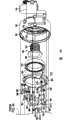
Fig. 2 is the closer view of shift assist apparatus;
Fig. 3 is to use the inclination interior views of specific embodiment of the pedal crank arm of shift assist apparatus;
Fig. 4 (A) and 4 (B) comprise the decomposition view of shift assist apparatus together;
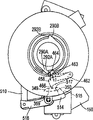
Fig. 5 is the view of the enclosure interior of expression shift assist apparatus;
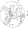
Fig. 6 is the angled view of the enclosing cover of shift assist apparatus;
Fig. 7 (A) is the view that the key role of position holding mechanism keeps sub-pusher dog when shift assist apparatus is in initial position;
Fig. 7 (B) is the view that drives the sub-pusher dog of bindiny mechanism when shift assist apparatus is in halted state and initial position;
Fig. 7 (C) is the close-up view that drives the sub-pusher dog of bindiny mechanism when shift assist apparatus is in halted state and initial position;
Fig. 7 (D) is the close-up view that drives the sub-pusher dog of bindiny mechanism when shift assist apparatus moves to driving condition;
Fig. 7 (E) is the total view that drives the sub-pusher dog of bindiny mechanism when shift assist apparatus is in driving condition;
Fig. 7 (F) is the view of shift assist apparatus before driving the disengagement of bindiny mechanism and pedal crank arm;
Fig. 7 (G) is the view of shift assist apparatus when driving the disengagement of bindiny mechanism and pedal crank arm;
Fig. 8 (A) is the view that drives the sub-pusher dog of bindiny mechanism when shift assist apparatus turns back to halted state and midway location;
Fig. 8 (B) is the view that the key role of position holding mechanism keeps sub-pusher dog when shift assist apparatus mediates;
Fig. 9 (A) is the view that drives the sub-pusher dog of bindiny mechanism when shift assist apparatus is in driving condition and midway location;
Fig. 9 (B) is the view that drives the sub-pusher dog of bindiny mechanism when shift assist apparatus turns back to halted state and final position;
Fig. 9 (C) is the view that middle position keeps sub-pusher dog when shift assist apparatus is in the final position;
Figure 10 keeps sub-pusher dog to throw off so that make the view of transmission device pusher dog of position holding mechanism when midway location moves when the Far Left key role;
Figure 11 (A) is the more detailed view that begins to operate of the sub-pusher dog of position holding mechanism when turning back to last position;
Figure 11 (B) be with the more detailed view that begins to operate of the sub-pusher dog of position holding mechanism before moving member engages;
Figure 11 (C) be with the close-up view that begins to operate of the sub-pusher dog of position holding mechanism before moving member engages;
Figure 12 is the view that the middle position of position holding mechanism after turning back to midway location keeps sub-pusher dog;
Figure 13 keeps sub-pusher dog to throw off so that make the view of transmission device pusher dog of position holding mechanism when initial position moves when the rightmost middle position;
Figure 14 is the view that the middle position of position holding mechanism after turning back to initial position keeps sub-pusher dog;
Figure 15 is the lateral plan of the bicycle of the cable bonded assembly specific embodiment between expression shift assist apparatus and the front chain shifter;
Figure 16 is mounted in the close-up view of specific embodiment of the cable deflector at bicycle rear portion; And
Figure 17 is mounted in the close-up view of specific embodiment of the cam mechanism on bicycle top.
The specific embodiment
Fig. 1 is combined with the lateral plan of specific embodiment of bicycle 10 that is used for helping at bicycle drive the device 14 of variable speed operation of the present invention.Bicycle 10 can be the bicycle of any kind, and bicycle 10 comprises representative type vehicle frame 18 in this embodiment, and it comprises pipe 22, first pipe 24, manages the 24 following pipes 26 that extend downwards, the seat pipe 30 that extends from last pipe 22, is arranged in down bottom bracket 32, a pair of seat stay 34 that extends back from bottom bracket 32 that pipe 26 and seat are managed 30 joint portions downwards from head.The vehicle seat of saddle form is installed on the vehicle frame 18 at the place, joint portion of last pipe 22 and seat pipe 30.Car fork 42 is rotatably supported in the first pipe 24, and front vehicle wheel 46 is rotatably supported on the lower end of car fork 42.The rotation direction of car fork 42 and wheel 46 is controlled with known manner by handlebar.Rear wheel 54 with a plurality of coaxial mounted flywheel (not shown) is rotatably supported in the place, joint portion of seat stay 34 and chain frame 38, and support a plurality of before the pedal assembly 58 of sprocket wheels 62 be rotatably supported in the bottom bracket 32.In this embodiment, three preceding sprocket wheels 62 and pedal assembly 58 coaxial and unitary rotation.Blockchain 66 with a plurality of before one of sprocket wheels 62 engage with a plurality of one of flywheels on the rear wheel 54 that are installed in.
Fig. 2 is the nearer view of shift assist apparatus 14.Shift assist apparatus 14 comprises by the tubulose installation component 300 (Fig. 4 B) that screws in bottom bracket 32 and is connected to housing 100 on the vehicle frame 18.Housing 100 remains on stable and the desired location with respect to vehicle frame 18 by the locating support 108 that engages with seat pipe 30, and enclosing cover 112 is connected on the housing 100 by the screw 116 that screws in the respective openings 354 (Fig. 5) in the housing 100.In this embodiment, first group of chain device cable 120 (Figure 15) of output control line material assembly 78 leaves shift assist apparatus 14 and extends towards the rear portion of bicycle, and second group of chain device cable 124 of output control line material assembly 78 is connected on the front chain shifter 70.When following discussion Figure 15~17, provide the detailed description of output control line material assembly 78.The crank arm 128 that forms pedal assembly 58 parts is installed in and extends through bottom bracket 32 so that on the crank shaft 132 of axis X rotation.The motor 150 (Fig. 1) that is connected to cable 82 is provided with the mode operation assisting device 14 be used for to describe below.
Fig. 3 is the inclination inside view of the specific embodiment of crank arm 128.Crank arm 128 comprises elongated crank arm main body 220, be positioned at an end and the crank shaft that has the perimeter surface that limits crank shaft mounting hole 299 and be used to be connected to the spline 228 on the complementary splines of axle 132 is installed projection 224 and is positioned at screw thread pedal mounting hole 228 on the other end.Annular actuating ring 270 has a plurality of formation spline 274 on the perimeter surface within it, so that engage with the complementary splines 278 that crank shaft is installed on the side direction penetralia outer surface on the projection 224 un-rotatably.The outer surface of driving ring 270 forms a pair of driving protrusion 290A and 290B, each protrusion have respectively leave mutually 180 degree and towards the rotation of crank arm 128 forwards to abut part 292A and 292B.In other words, abut part 292A and 292B clockwise direction towards Fig. 3, and towards the anticlockwise direction of Fig. 2.Abut part 292A and 292B along from the outward extending imaginary line of the rotational axis x of pedal assembly 58, and the outer surface of projection 224 is installed perpendicular to crank shaft.
Fig. 4 (A) and 4 (B) comprise the decomposition view of gear shift auxiliary device 14 together.Fig. 5 is expression housing 100 in-to-in views, and Fig. 6 is the angled view of enclosing cover 112.Described tubulose installation component 300 has screw thread outer surface 304 and flange 308, wherein screw thread outer surface 304 screws in the interior perimeter surface (not shown) of complementary threads in the bottom bracket 32, and flange 308 abuts the installation surface 310 of housing 100, so that housing 100 is fixed on the bottom bracket 32.Sleeve bearing 312 is installed in the bearing seat 316 in the housing 100 so that pusher dog installation component 320 under the rotatably support annular wherein descends pusher dog installation component 320 to be connected on the annular upper poking claw installation component 324 via screw 328.The actuation spring 332 of throwing off member or inclined-plane with following describing mode as pusher dog is installed on the periphery of housing 100 via pad 335 and the screw 336 that screws in opening 338.Have the location and abut part 342, pusher dog and throw off the arc pusher dog control member 340 that wall 344 and pusher dog discharge breach 348 and be installed in via pair of screws 116 on the periphery of housing 100, screw 116 extends through the opening 353 in enclosing cover 112, the pusher dog control member 340 and enters the opening 354 of reply mutually on the periphery of housing 100.Shown in Fig. 5 was clearer, housing 100 also had pusher dog disengagement wall 357, pusher dog disengagement wall 358, inclined-plane 349, location, the location abuts part 350 and pusher dog is thrown off wall 359, the following description of its function.
Annulus cable connecting panel 355 with cable connection opening 356 is installed on the upper poking claw installation component 324 via key opening 361, makes cable connecting panel 355 can spur or discharge first group of chain device cable 120 when 324 motions of upper poking claw installation component.As Fig. 4 (A) with shown in 6, enclosing cover 112 comprises plate portion 500 and cylindrical part 504, and wherein otch 508 (Fig. 6) limits the midway location maintenance and abuts part 509, the following description of its function.
The driving pusher dog assembly that comprises driven element pusher dog 360,364 and driven element pusher dog 368,372 is installed in down on the pusher dog installation component 320 pivotally, so that be clipped in down between pusher dog installation component 320 and the upper poking claw installation component 324.More especially, driven element pusher dog 360 is installed on the pivot 376 on the driven element pusher dog 364 pivotally, and pivot 376 also is pivotally mounted to down on the opening 378 in the pusher dog installation component 320, makes two sub-pusher dogs 360,364 be installed in down pivotally on the pusher dog installation component 320.Driven element pusher dog 360 comprises moving member bonding part 380 and pusher dog control part 384.Moving member bonding part 380 is arranged to engage and is abutted one of part 292A and 292B on the crank arm 128, and pusher dog control part 384 is arranged to the pusher dog control part 388 on the sub-pusher dog 364 of engages drive.Driven element pusher dog 360 is by being installed in spring 389 bias voltage in the clockwise direction on the upper poking claw installation component 324 via screw 390.More especially, the spring arm 391 of spring 389 extends through the opening 393 (Fig. 7 (A)) in the upper poking claw installation component 324, and the moving member bonding part 380 of contact driven element pusher dog 360.Therefore, the pusher dog control part 388 on the pusher dog control part 384 bias voltage driven element pusher dogs 364 of driven element pusher dog 360 makes both bias voltages in the clockwise direction of driven element pusher dog 360 and driven element pusher dog 364.Pusher dog control part 388 on the driven element pusher dog 364 comprises control pin 392, the following description of its function.
Similarly, driven element pusher dog 368 is installed on the pivot 400 on the driven element pusher dog 372 pivotally, and pivot 400 also is installed in down pivotally on the opening (not shown) in the pusher dog installation component 320, makes two driven element pusher dogs 368 and 372 be installed in down pivotally on the pusher dog installation component 320.Driven element pusher dog 368 comprises moving member bonding part 404 and pusher dog control part 408.Moving member bonding part 404 is arranged to engage and is abutted one of part 292A and 292B on the crank arm 128, and pusher dog control part 408 is arranged to the pusher dog control part 412 on the sub-pusher dog 372 of engages drive.Driven element pusher dog 368 is by being installed in spring 420 bias voltage in the clockwise direction on the upper poking claw installation component 324 via screw 428.More especially, the spring arm 424 of spring 420 extends through the opening 430 (Fig. 7 (A)) in the upper poking claw installation component 324, and the moving member bonding part 404 of contact driven element pusher dog 368.Therefore, the pusher dog control part 412 on the pusher dog control part 408 bias voltage driven element pusher dogs 372 of driven element pusher dog 368 makes both bias voltages in the clockwise direction of driven element pusher dog 368 and driven element pusher dog 372.Pusher dog control part 412 on the driven element pusher dog 372 comprises control pin 416, the following description of its function.
Comprise that master site keeps sub-pusher dog 450,458 and aided location to keep the position of sub-pusher dog 454,462 to keep the pusher dog assembly to be mounted to clamping upper poking claw installation component 324 pivotally.More especially, pivot 470 is installed in down on the opening 471 of pusher dog installation component 320, the aided location that supports pivotally on the right side of upper poking claw installation component 324 keeps sub-pusher dog 454, extend through the opening 472 in the upper poking claw installation component 324, and the master site that supports pivotally on upper poking claw installation component 324 left sides keeps sub-pusher dog 450.Aided location keeps sub-pusher dog 454 to comprise moving member bonding part 453 and midway location retaining part 452, and its master site that limits on its bottom keeps sub-pusher dog contact flange 452a.Master site keeps sub-pusher dog 450 to comprise that the position keeps tooth 456 to contact the local stria 455 that abuts part 455a that master site keeps sub-pusher dog contact flange 452a with forming.Spring leg 488 conter clockwises (radially outward) the bias voltage master site that is installed in the spring 490 on the upper poking claw installation component 324 by screw 491 keeps sub-pusher dog 450.Aided location keeps spring 474 on cw (radially inside) direction the bias voltage of sub-pusher dog 454 by installing around pivot 470.But aided location keeps sub-pusher dog 454 radially outward to keep by flange 452a and the contact that abuts between the part 455a usually, this be since the spring force of spring 490 greater than the spring force of spring 474.
Similarly, pivot 480 is installed in down on the opening (not shown) of pusher dog installation component 320, the aided location that supports pivotally on the right side of upper poking claw installation component 324 keeps sub-pusher dog 462, extend through the opening 484 in the upper poking claw installation component 324, and the master site that supports pivotally on upper poking claw installation component 324 left sides keeps sub-pusher dog 458.Aided location keeps sub-pusher dog 462 to comprise moving member bonding part 464 and midway location retaining part 463, and its master site that limits on its bottom keeps sub-pusher dog contact flange 463a.Master site keeps sub-pusher dog 458 to comprise that the position keeps tooth 466 to contact the local stria 466 that abuts part 465a that master site keeps sub-pusher dog contact flange 632a with forming.Spring leg 489 conter clockwises (radially outward) the bias voltage master site of spring 490 keeps sub-pusher dog 458.Aided location keeps spring 492 on cw (radially inside) direction the bias voltage of sub-pusher dog 462 by installing around pivot 480.But aided location keeps sub-pusher dog 462 radially outward to keep by flange 463a and the contact that abuts between the part 465a usually, this be since the spring force of spring 490 greater than the spring force of spring 492.To descend pusher dog installation component 320, upper poking claw installation component 324, master site to keep sub-pusher dog 450,458, aided location to keep sub-pusher dog 454,462 and driven element pusher dog 360,364,368,372 to link together in this way and make these parts dismantle so that assembling and maintenance from auxiliary sub-device 14 as one unit.
Shown in Fig. 5,7 (C) and 7 (D), motor 150 comprises the drive controlling chaining part 510 that is installed in pivotally on the drive controlling arm 518, and drive controlling arm 518 is installed on the pivot 516 then pivotally.Drive controlling chaining part 510 is connected to one heart and is installed in rotation on the drive controlling ring 511 in the housing 100 (the very little part of having only of drive controlling ring 511 is represented in the accompanying drawings).Drive controlling ring 511 has the movable drive controlling that extends through the drive controlling opening 513 in the housing 100 and abuts part 512.When drive controlling abuts part 512 and is positioned at position shown in Fig. 5 and 7 (C), motor 150 can rotate control loop 511 via drive controlling chaining part 510 and drive controlling arm 518 in the clockwise direction so, make drive controlling abut the right hand edge that part 512 moves to drive controlling opening 513, shown in Fig. 7 (D).Similarly, when drive controlling abuts part 512 and is positioned at the right hand edge of drive controlling opening 513, motor 150 can rotate counterclockwise drive controlling ring 511 via drive controlling chaining part 510 and drive controlling arm 518, makes drive controlling abut the left hand edge that part 512 returns drive controlling opening 513.Motor 150 is also operated to have and is discharged the release control pusher dog 514 that control abuts part 517, and this abuts part and extend through opening 515 during the pusher dog releasing operation, as following description.
Fig. 7 (A) is the view that the master site of position holding mechanism when auxiliary device 14 is positioned at initial position keeps sub-pusher dog 450 and 458, and Fig. 7 (B) is that the aided location of position holding mechanism when gearshift 14 is positioned at halted state and initial position keeps sub-pusher dog 454 and 462 and drive the driven element pusher dog 360,364 of bindiny mechanism and 368,372 view.If front chain shifter 70 is following types, promptly spur output control line material assembly 78 and cause front chain shifter 70 that blockchain 66 is moved on major diameter (at a high speed) sprocket wheel from minor diameter (low speed) sprocket wheel, Fig. 7 (A) expression auxiliary device 14 is in low-speed position so.In this position, the location that master site keeps the position of sub-pusher dog 458 to keep tooth 466 to abut pusher dog control member 340 abuts part 342; Master site keeps the position of sub-pusher dog 450 to keep tooth 456 to be in rest position; The control pin 416 of driven element pusher dog 372 abuts the radially biasing force of inside antagonistic spring 420 of part 512 by the drive controlling in the housing 100; And the control pin 392 of driven element pusher dog 364 abuts the radially biasing force of inside antagonistic spring 389 of part 357 by the drive controlling of housing 100.Driven element pusher dog 360,364 and 368,372 this location guarantee that the moving member bonding part 380 and 404 of driven element pusher dog 360 and 368 radially inwardly keeps respectively, make moving member bonding part 380 and moving member bonding part 404 not contact and abut part 292A, 292B on the crank arm 128.
Fig. 7 (C)-7 (E) expression driven element pusher dog 360,364 and 368,372 is in the operation when halted state is transformed into starting state.When the cyclist uses shift controller 84 to provide to upgrade order, motor 150 motion drive controlling chaining part 510 and drive controlling arms 518 make drive controlling abut part 512 moves to the described drive controlling opening 513 of Fig. 7 (D) from the position shown in Fig. 7 (C) right hand edge.At this moment, driven element pusher dog 372 clockwise rotates, and control pin 416 biasing forces according to spring 420 radially outward move in the pusher dog release breach 348 of pusher dog control member 340.Driven element pusher dog 368 clockwise rotates shown in Fig. 7 (D) and 7 (E) equally, and the radially inwardly motion of the moving member bonding part 404 of driven element pusher dog 368.In this position, when crank arm 128 was positioned at suitable turned position, of will engage on the crank arm 128 in the moving member bonding part 404 of driven element pusher dog 368 abutted part 292A or 292B.When this situation occurred, the turning effort of crank arm 128 was delivered to down on pusher dog installation component 320 and the upper poking claw installation component 324 via driven element pusher dog 368.Therefore, master site keep sub-pusher dog 450 and 458 and driven element pusher dog 360,364 and 368 and 372 rotate counterclockwise together.
When pusher dog installation component 320 and upper poking claw installation component 324 rotated counterclockwise instantly, master site kept the position of sub-pusher dog 450 to keep tooth 456 to slide along locating inclined-plane 349, crossed pusher dog disengagement wall 359 and slide to exceed to locate to abut part 350, shown in Fig. 7 (F).The control pin 392 of throwing off the driven element pusher dog 364 that wall 357 radially inwardly keeps by pusher dog moves to drive controlling and abuts position below the part 512, and radially inwardly keeps.At this moment, the control pin 416 of driven element pusher dog 372 slides along the inner radial surface of bow type spring 332, and radially inwardly promotes.When the control pin 416 of promoter pusher dog 372 radially inwardly moved, driven element pusher dog 368 rotated counterclockwise, and the moving member bonding part 404 of driven element pusher dog 368 abuts part 292A with engaging of crank arm 118 gradually or 292B throws off.
When driven element pusher dog 368 abuts time that part 292A or 292B throw off and depends on the intensity of bow type spring 332 with engaging.More especially, shown in Fig. 7 (F), because driven element pusher dog 368 and engage the engaging force abut between part 292A or the 292B, the radially inner power of control pin 416 opposing bow type springs 332 make bow type spring 332 beginning radial and outward deformation.But little by little, the spring force of bow type spring 332 and radially inner path overcome this engaging force, and driven element pusher dog 368 abuts part 292A or 292B and throws off with engaging.If bow type spring 332 weaknesses, driven element pusher dog 368 will keep engaging longer with abut part 292A or the 292B that engage so, and compare with the situation that bow type spring 332 is firm, master site keeps the position of sub-pusher dog 450 to keep tooth 456 further to move surpassing the location abutting part 350.
When driven element pusher dog 368 with engage when abutting part 292A or 292B and throwing off, bow type spring 332 further radially inwardly promotes control pin 416 as Fig. 7 (G) shown in, and the space between closed bow type spring 332 and the pusher dog disengagement wall 358.At this moment, following pusher dog installation component 320 and upper poking claw installation component 324 clockwise rotate slightly owing to the biasing force of retracing springs in the front chain shifter 70.The control pin 416 of driven element pusher dog 372 moves to the pusher dog shown in Fig. 8 (A) and 8 (B) and throws off wall 358 radially inner positions, and master site keeps the position of sub-pusher dog 450 to keep tooth 456 to move to abutting the position that the location abuts part 350.Net result be output control line material assembly 78 cause the interim motion blockchains 66 of front chain shifter 70 to surpass the target sprocket wheel and then blockchain 66 is turned back to target sprocket wheel positions aligning on.This displacement phenomenon excessively is known, and helps blockchain to be transformed on the large diameter sprocket from the minor diameter sprocket wheel.What should understand easily was that the amount that is shifted can be adjusted by the suitable intensity of selecting bow type spring 332.
When the cyclist used shift controller 84 to provide another to upgrade order, motor 150 motion drive controlling once more chaining part 510 and drive controlling arm 518 made drive controlling abut the right hand edge that part 512 moves to drive controlling opening 513.At this moment, driven element pusher dog 364 clockwise rotates shown in Fig. 9 (A), and control pin 392 biasing forces according to spring 389 radially outward move in the pusher dog release breach 348 of pusher dog control member 340.Driven element pusher dog 360 also clockwise rotates, and the radially inwardly motion of the moving member bonding part 380 of driven element pusher dog 360.On this position, when crank arm 128 was positioned at suitable turned position, of will engage on the crank arm 128 in the moving member bonding part 380 of driven element pusher dog 360 abutted part 292A or 292B.When this situation occurred, the turning effort of crank arm 128 was delivered to down on pusher dog installation component 320 and the upper poking claw installation component 324 via driven element pusher dog 360.Therefore, master site keep sub-pusher dog 450 and 458 and driven element pusher dog 360,364 and 368 and 372 rotate counterclockwise together.
When driven element pusher dog 360,364 and 368,372 during towards rotated position shown in Fig. 9 (B), the control pin 416 of throwing off the driven element pusher dog 372 that wall 358 radially inwardly keeps by pusher dog moves to pusher dog and throws off the radially inner position of wall 359 and radially inwardly keep.Equally, the control pin 392 of driven element pusher dog 364 slides along bow type spring 332, and radially inwardly promotes in described driven element pusher dog 372 identical modes.At this moment, master site keeps the position of sub-pusher dog 458 to keep tooth 466 to slide along locating inclined-plane 349, crosses pusher dog disengagement wall 359 and slide to exceed to locate to abut part 350 so that formed the displacement effect.
When the control pin 392 of driven element pusher dog 364 radially inwardly moves, driven element pusher dog 364 rotates counterclockwise, and the moving member bonding part 380 of driven element pusher dog 364 abuts part 292A with engaging of crank arm gradually in described driven element pusher dog 372 identical modes or 292B throws off.When this situation occurring, following pusher dog installation component 320 and upper poking claw installation component 324 clockwise rotate slightly owing to the biasing force of retracing springs in the front chain shifter 70.So the control pin 392 of driven element pusher dog 364 moves to the radially inner side that pusher dog is thrown off wall 358 shown in Fig. 9 (B), and master site keeps the position of sub-pusher dog 458 to keep tooth 466 to abut the location abutting part 350, shown in Fig. 9 (C).Auxiliary device 14 and output control line material assembly 78 are positioned at high speed position at this moment.
When the cyclist used shift controller 84 to provide to lower category order, motor 150 pivoted on anticlockwise direction shown in Figure 10 and discharges control pusher dog 514.Therefore, discharge control and abut part 517 and extend through opening 515 in the housing 100, press master site and keep the position of sub-pusher dog 458 to keep tooth 466, it is clockwise rotated, and positioning teeth 466 and position are kept abutting part 350 throw off.Simultaneously, the part 465a that abuts in the stria 465 makes master site keep sub-pusher dog contact flange 463a and aided location to keep sub-pusher dog 462 to clockwise rotate (radially inside) according to the biasing force of spring 492.Therefore, the moving member bonding part 464 that aided location keeps sub-pusher dog 462 is in the radially inside location of the cylindrical part 504 of enclosing cover 112, and aided location keeps the midway location retaining part 463 of sub-pusher dog 462 to extend through otch 508, as the more special expression of Figure 11 (A)-11 (C).Part 350 is thrown off and the biasing force of front chain shifter 70 interior retracing springs, following pusher dog installation component 320 and the motion of upper poking claw installation component 324 cws because positioning teeth 466 abuts with the location.
Otch 508 in the enclosing cover 112 makes master site keep sub-pusher dog 458 and aided location to keep sub-pusher dog 462 to clockwise rotate slightly.Simultaneously, following pusher dog installation component 320, upper poking claw installation component 324 and cable connecting panel 355 clockwise rotate equally, so that discharge first group of chain device cable 120.But, shown in Figure 11 (C) is clearer, throw off even master site keeps the position of sub-pusher dog 458 to keep tooth 466 to abut part 350 with the location fully, aided location keeps the midway location retaining part 463 of sub-pusher dog 462 and is formed on midway location on the enclosing cover 112 keeping abutting contact preventing aided location between the part 509 and keeping sub-pusher dog 462 and the further rotation of pusher dog maintenance installation component 320 and upper poking claw installation component 324 down.In this case, master site keeps the position of sub-pusher dog to keep tooth 466 to stop in the roughly halfway of pusher dog disengagement wall 359.This is very beneficial for preventing down that pusher dog installation component 320, upper poking claw installation component 324 and cable connecting panel 355 horse back conter clockwises move to the middling speed position.
On the other hand, aided location keeps the moving member bonding part 464 of sub-pusher dog 462 to be positioned at a position that abuts part 292A or 292B that contacts on the crank arm 128 now, shown in Figure 11 (B) and 11 (C).Because moving member bonding part 646 has inclined surface, aided location keeps sub-pusher dog 462 radially outward to promote by abutting part 292A or 292B, therefore aided location is kept the midway location retaining part 463 of sub-pusher dog 462 and the midway location on the enclosing cover 112 to keep abutting part 509 disengagements.Then pusher dog installation component 320 and upper poking claw installation component 324 and aided location keep sub-pusher dog 462 and master site to keep sub-pusher dog 458 to clockwise rotate middling speed position shown in Figure 12 under making.Described motion also is delivered on the cable connecting panel 355, makes output wire rod assembly 78 be positioned at the middling speed position.
Use midway location on the enclosing cover 112 to keep abutting part 509 and aided location keeps the midway location retaining part 463 of sub-pusher dog 462 and moving member bonding part 464 to make auxiliary device 14 postpone the rotation of pusher dog adapter plate 320, upper poking claw adapter plate 324 and cable connecting panel 355 down, up to one abut part 292A or 292B contact aided location and keep the moving member bonding part 464 of sub-pusher dog 462 till.This makes the timing of gear-change operation be provided with very accurately.This timing is extremely important when impelling the blockchain displacement structure to be arranged on the sprocket wheel.In other words, abutting part 292A and 292B can be with respect to impelling the vehicle displacement structure to be arranged on obliquity so that improves gear-change operation.
When the cyclist used shift controller 84 to provide once more to lower category order, motor 150 pivoted in the counterclockwise direction once more and discharges control pusher dog 514, and discharged the control that extends through the opening 515 in the housing 100 and abut part 517.Release control abuts part 517 and presses the position maintenance tooth 456 that master site keeps sub-pusher dog 450, and keeps tooth 456 and location to abut part 350 disengagements the position, as shown in figure 13.Auxiliary device 14 then with shown in the same way as operation so that postpone the rotation of pusher dog adapter plate 320, upper poking claw adapter plate 324 and cable connecting panel 355 down, up to one abut part 292A or 292B contact aided location and keep the moving member bonding part 453 of sub-pusher dog 454 till.When this situation occurring, aided location keeps sub-pusher dog 454 radially outward to promote by abutting part 292A or 292B, makes aided location keep sub-pusher dog 454 and master site to keep sub-pusher dog 450 to clockwise rotate low-speed position shown in Figure 14 thus.Described motion also is delivered to down pusher dog installation component 320, upper poking claw installation component 324 and cable connecting panel 355, makes output control line material assembly be positioned at low-speed position.
Figure 15 is the lateral plan (auxiliary device 14 removes in this figure) of specific embodiment of bicycle 10 of the embodiment of the control wire rod assembly 78 between expression auxiliary device 14 and the front chain shifter 70.In this embodiment, wish to reduce the cable connecting panel 355 of auxiliary device 14 and the steel wire stroke between the front chain shifter 70.For this reason, the first group of chain device cable 120 extends towards the bicycle rear portion from the cable connecting panel 355 of auxiliary device 14.Shown in Figure 15 and 16, the first group of chain device cable 120 pass with roller 600 be on form and the joint portion that is installed in rotation on left side seat stay 34 and chain frame 38 the cable deflector around.After this, first group of chain device cable 120 continues to extend towards saddle 39.
As shown in figure 17, first group of chain device cable 120 passes the coiling surface 608 of cam 612, and this cam is installed on the vehicle frame 18 rotationally via the place, joint portion of bearing assembly 614 at last pipe 22, seat pipe 30 and seat stay 34.The terminal part of first group of chain device cable 120 ends at cable fastener 616.Cam 612 comprises a plurality of bias voltages adjustment openings 620 that can be connected to selectively on the biasing spring 624.Biasing spring 624 can be used to set the initial position of cam 612 and provides biasing force to dialling on the chain device 70.In this embodiment, biasing spring 624 is connected on the vehicle seat 39.Butt hook 630 is pivotally connected on the cam 612 via pivot 634.Butt hook 630 is connected on second group of chain device cable 124, and cable 124 is fastened on the front chain shifter 70 then.This configuration can reduce only about half of steel wire stroke.
In another embodiment, group chain device cable that leaves auxiliary device 14 can directly be fastened on the front chain shifter 70, and the steel wire stroke can use structures such as cam, speed reduction gearing group chain device to adjust.As selection, the radial position of the cable connection opening 356 that the steel wire stroke can be by changing cable connecting panel 355 is adjusted.In another embodiment, can cancel annulus cable connecting panel 355.In this case, following pusher dog installation component 320 can be configured with the cam 700 shown in Fig. 4 (B), and output wire rod assembly 78 can U. S. application No.6, and 443,032 modes that disclose are connected on the bar (not shown) of cooperating with cam 700.
Though more than be the description of different embodiments of the invention, can under the situation that does not depart from spirit and scope of the invention, adopt other modification.For example, though make electricity consumption operation motor 150 motion drive controlling abut part 512, also can use the mechanical gear shift control setup.Though different members is suitable for rotating with revolving member and cooperating the motion outside can also rotating.As required, can change size, shape, position or the orientation of different parts.Shown in direct connection or the parts that are in contact with one another can have intermediate structure therein.The function of an element can be undertaken by two elements, and vice versa.The 26S Proteasome Structure and Function of an embodiment can adopt in another embodiment.All advantages do not need to be present in simultaneously in the certain embodiments.Than combine separately or with other features independent description of other inventions of can be used as the applicant of each feature of prior art uniqueness, it comprises by the structure of these feature instantiations and/or functional idea.Therefore, scope of the present invention should not limited by disclosed ad hoc structure or surperficial ad hoc structure or the feature that initial interest place.
Claims (24)
1. one kind is used to use the auxiliary device that helps the bicycle shift from the power of pedal assembly, and it comprises:
Housing (100), itself and crank shaft (132) are fixedly mounted on the bottom bracket (32) coaxially;
Transmission device, it comprises following pusher dog installation component (320) and the upper poking claw installation component (324) that interfixes, described transmission device is pivotally mounted in the housing (100), and a cable (120) that is connected with group chain device is installed on the upper poking claw installation component (324) by cable connecting panel (355);
Drive bindiny mechanism, it comprises the first driven element pusher dog (360) and the second driven element pusher dog (368), and they are installed in down on the pusher dog installation component (320) pivotally, and are clipped in down between pusher dog installation component (320) and the upper poking claw installation component (324);
Position holding mechanism, it comprises that the position keeps sub-pusher dog (450,458,454,462), they are installed on the upper poking claw installation component (324) pivotally;
When upgrading, crank arm of pedal assembly (128) and the described first and second driven element pusher dogs (360,368) one of engage, thereby driving transmission device rotates towards first direction, rear crank arm (128) and the described first and second driven element pusher dogs (360 turn an angle, 368) the described driven element pusher dog in is disengaged, this moment, the position kept sub-pusher dog (450,458) one of be in and abut the holding position that part (350) engages with the location and prevent the transmission device backward rotation, wherein along with rotation cable (120) pulling of transmission device is dialled the chain device and realized shift
When lowering category, the position that is in the holding position keeps sub-pusher dog (450,458) to break away from the holding position, resets in the effect underdrive member backward rotation of cable (120), dials the chain device and realizes shift thereby discharge.
2. device as claimed in claim 1 is characterized in that, the position keeps sub-pusher dog (450,458) disengaging holding position to be undertaken by discharging control pusher dog (514).
3. device as claimed in claim 2, it is characterized in that, also be provided with drive controlling and abut part (512), described driving bindiny mechanism comprises the third and fourth driven element pusher dog (372,364), the described third and fourth driven element pusher dog (372,364) with the described first and second driven element pusher dogs (360,368) install coaxially, the described first and second driven element pusher dogs (360,368) pusher dog control part (408,384) the described third and fourth driven element pusher dog (372 of bias voltage, 364) pusher dog control part (412,388), abut on the part (512) so that be resisted against drive controlling, thus the described first and second driven element pusher dogs (360,368) remain on its disengaged position; When upgrading, motor (150) makes drive controlling abut part (512) displacement via drive controlling chaining part (510) and drive controlling arm (518), thus the described first and second driven element pusher dogs (360,368) both radially outward rotate to engage position.
4. device as claimed in claim 3, it is characterized in that, also be provided with bow type spring (332), when transmission device when first direction rotates, pusher dog control part (412,388) is being resisted bow type spring (332), and the described first and second driven element pusher dogs (360,368) are disengaged with crank arm (128) gradually.
5. device as claimed in claim 3 is characterized in that, also is provided with the position and keeps abutting part (350), and the position keeps sub-pusher dog (450,458) to be resisted against the position by its positioning teeth (466,456) and keeps abutting the last holding position that is in of part (350).
6. device as claimed in claim 1 is characterized in that, position holding mechanism comprises that also aided location keeps sub-pusher dog (462,454), is used for keeping sub-pusher dog (458,450) to match with the position and controls the time of gear shift.
7. device as claimed in claim 1 is characterized in that, crank arm (128) engages with described first and second driven element pusher dogs (360,368) at engage position by the part (292A, 292B) that abuts disposed thereon.
8. device as claimed in claim 3, it is characterized in that, the described first and second driven element pusher dogs (360,368) and two positions keep sub-pusher dog (458,450) to be arranged in down separatedly on the circumference of pusher dog installation component (320), to realize the switching of basic, normal, high shelves.
9. device as claimed in claim 1 is characterized in that, it also comprises and is applicable to the locating support (108) fixing with respect to vehicle frame.
10. device as claimed in claim 9 is characterized in that, drive bindiny mechanism and engage with the pedal assembly in the radially inside position of transmission device, and wherein the position retaining member engages with locating support (108) in the position radially outward of transmission device.
11. one kind is used to use the auxiliary device that helps the bicycle drive operation from the power of pedal assembly, it comprises:
Transmission device, it comprises following pusher dog installation component (320) and the upper poking claw installation component (324) that interfixes, described transmission device is pivotally mounted in the housing (100), one cable (120) that is connected with group chain device is installed on the upper poking claw installation component (324) by cable connecting panel (355), wherein transmission device in the clockwise direction with anticlockwise direction in a direction on rotate so that the driving device of the bicycle that upgrades, and wherein transmission device in the clockwise direction with anticlockwise direction in other direction on rotate so that the driving device of the bicycle that lowers category;
Drive bindiny mechanism, this mechanism transmission device is connected on the pedal assembly in case in the clockwise direction with anticlockwise direction in a direction on rotation drive machine, drive bindiny mechanism and comprise:
The first driven element pusher dog (368) that between the first moving member engage position and the first moving member disengaged position, moves;
The first driven element pusher dog (368) is remained on the second driven element pusher dog (372) on the first moving member disengaged position;
Make the moving member engagement member releasing mechanism that the described first driven element pusher dog (368) moves from the first moving member disengaged position towards the first moving member engage position; And
The first moving member engagement member is reset to the moving member engagement member Bringing-back mechanism of the first moving member disengaged position;
Prevent transmission device in the clockwise direction with anticlockwise direction in the position holding mechanism of the opposing party's upward movement, wherein position holding mechanism is included in the position of moving between primary importance holding position and the primary importance releasing position and keeps sub-pusher dog (450), wherein when the position keeps sub-pusher dog (450) to be positioned at the primary importance holding position, the position keeps sub-pusher dog (450) and location to abut part (350) engaging, and rotates so that prevent transmission device; And
Keep sub-pusher dog (450) to abut part (350) disengagement from the location so that the release control pusher dog (514) that transmission device rotates the position.
12. device as claimed in claim 11, it is characterized in that, drive bindiny mechanism and also be included in the 3rd driven element pusher dog (360) that moves between the second moving member engage position and the second moving member disengaged position, wherein 4 wheel driven mover pusher dog (364) remains on described the 3rd driven element pusher dog (360) on the second moving member disengaged position, and moving member engagement member releasing mechanism makes the second moving member engagement member move towards the second moving member engage position.
13. device as claimed in claim 12, it is characterized in that, moving member engagement member releasing mechanism comprises movable drive controlling ring (511), and one in feasible described first driven element pusher dog (368) that engages of the motion of wherein movable drive controlling ring (511) and the 3rd driven element pusher dog (360) towards corresponding first moving member engage position and the motion of the second moving member engage position.
14. device as claimed in claim 13, it is characterized in that movable drive controlling ring (511) comprises that the first driven element pusher dog (368) that will engage and a drive controlling that remains on the corresponding sports member disengaged position in the 3rd driven element pusher dog (360) abut part (512).
15. device as claimed in claim 14 is characterized in that, the motion of movable drive controlling ring (511) abuts part (512) from the first driven element pusher dog (368) that engages and a disengagement the 3rd driven element pusher dog (360) with drive controlling.
16. one kind is used to use the auxiliary device that helps the bicycle drive operation from the power of pedal assembly, it comprises:
Transmission device, it comprises following pusher dog installation component (320) and the upper poking claw installation component (324) that interfixes, described transmission device is pivotally mounted in the housing (100), one cable (120) that is connected with group chain device is installed on the upper poking claw installation component (324) by cable connecting panel (355), wherein on the direction of transmission device in first direction and second direction motion so that the driving device of the bicycle that upgrades, and wherein the opposing party upward movement of transmission device in first direction and second direction so that the driving device of the bicycle that lowers category;
Drive bindiny mechanism, the pedal assembly is connected on the moving member in this mechanism so that motion work on the direction in first direction and second direction drives bindiny mechanism and comprises:
The first driven element pusher dog (368) that between the first moving member engage position and the first moving member disengaged position, moves;
The first driven element pusher dog (368) is remained on the second driven element pusher dog (372) on the first moving member disengaged position;
The moving member engagement member releasing mechanism that the driven element pusher dog (368) of winning is moved from the first moving member disengaged position towards the first moving member engage position; And
The first driven element pusher dog (368) is reset to the moving member engagement member Bringing-back mechanism of the first moving member disengaged position;
Prevent the position holding mechanism of transmission device the opposing party's upward movement in first direction and second direction, wherein position holding mechanism is included in the position of moving between primary importance holding position and the primary importance releasing position and keeps sub-pusher dog (450), wherein when the position keeps sub-pusher dog (450) to be positioned at the primary importance holding position, the position keeps sub-pusher dog (450) and location to abut part (350) engaging, so that prevent the transmission device motion;
Elastic component, this elastic component make the interim motion of transmission device and engage so that prevent the position of transmission device motion above abutting part (350) with the location usually with position holding mechanism; And
Keep sub-pusher dog (450) to abut part (350) disengagement from the location so that the position retaining member releasing mechanism of transmission device motion the position.
17. device as claimed in claim 16 is characterized in that, elastic component forms the part of moving member engagement member Bringing-back mechanism.
18. device as claimed in claim 17 is characterized in that, moving member engagement member Bringing-back mechanism comprises:
Cause the first driven element pusher dog (368) to move to the disengagement inclined-plane of the first moving member disengaged position; And
The first driven element pusher dog (368) is remained on disengagement wall on the first moving member disengaged position.
19. device as claimed in claim 18 is characterized in that, elastic component has formed the disengagement inclined-plane.
20. device as claimed in claim 19 is characterized in that, throws off the inclined-plane and comprises leaf spring.
21. device as claimed in claim 18 is characterized in that, the surface of throwing off the inclined-plane is towards the first surface of throwing off wall.
22. device as claimed in claim 21, it is characterized in that, the first driven element pusher dog (368) moves between the first surface of surface of throwing off the inclined-plane and disengagement wall, and remains on the first moving member disengaged position at the second surface place of the disengagement wall relative with the first surface of throwing off wall.
23. device as claimed in claim 22 is characterized in that, throws off the inclined-plane and comprises leaf spring.
24. one kind is used to use the auxiliary device that helps the bicycle drive operation from the power of pedal assembly, it comprises:
Transmission device, it comprises following pusher dog installation component (320) and the upper poking claw installation component (324) that interfixes, described transmission device is pivotally mounted in the housing (100), one cable (120) that is connected with group chain device is installed on the upper poking claw installation component (324) by cable connecting panel (355), wherein on the direction of transmission device in first direction and second direction motion so that the driving device of the bicycle that upgrades, and wherein the opposing party upward movement of transmission device in first direction and second direction so that the driving device of the bicycle that lowers category;
Drive bindiny mechanism, the pedal assembly is connected on the moving member in this mechanism so that motion work on the direction in first direction and second direction;
Position holding mechanism, this mechanism prevents the opposing party upward movement of transmission device in first direction and second direction; And
Wherein drive bindiny mechanism and position holding mechanism comprises together:
Be connected to down the first and second driven element pusher dogs (368,360) on the pusher dog installation component (320), the wherein said first and second driven element pusher dogs (368,360) move between the first moving member engage position and the first moving member disengaged position;
The position that is connected on the upper poking claw installation component (324) keeps sub-pusher dog (450,458), and wherein the position keeps sub-pusher dog (450,458) to move between primary importance holding position and primary importance releasing position;
Wherein upper and lower pusher dog installation component (320,324), the first and second driven element pusher dogs (368,360) and position keep sub-pusher dog (450,458) to link together, and make them can be used as one unit and dismantle from auxiliary device.
Applications Claiming Priority (2)
| Application Number | Priority Date | Filing Date | Title |
|---|---|---|---|
| US10/616,171 US7011590B2 (en) | 2003-07-08 | 2003-07-08 | Shift assist apparatus for a bicycle transmission |
| US10/616171 | 2003-07-08 |
Publications (2)
| Publication Number | Publication Date |
|---|---|
| CN1576158A CN1576158A (en) | 2005-02-09 |
| CN100457540C true CN100457540C (en) | 2009-02-04 |
Family
ID=33452674
Family Applications (1)
| Application Number | Title | Priority Date | Filing Date |
|---|---|---|---|
| CNB2004100635114A Expired - Fee Related CN100457540C (en) | 2003-07-08 | 2004-07-08 | Shift assist apparatus for a bicycle transmission |
Country Status (6)
| Country | Link |
|---|---|
| US (1) | US7011590B2 (en) |
| EP (1) | EP1495959B1 (en) |
| JP (1) | JP2005029156A (en) |
| CN (1) | CN100457540C (en) |
| DE (1) | DE602004012662T2 (en) |
| TW (1) | TWI240693B (en) |
Families Citing this family (8)
| Publication number | Priority date | Publication date | Assignee | Title |
|---|---|---|---|---|
| FR2878499B1 (en) * | 2004-12-01 | 2007-02-16 | Salomon Sa | SPEED CHANGE CONTROL DEVICE FOR CHAIN AND SPROCKET TRANSMISSION SYSTEM |
| US8272293B2 (en) * | 2010-08-24 | 2012-09-25 | Shimano Inc. | Bicycle shift operating device |
| US9651138B2 (en) | 2011-09-30 | 2017-05-16 | Mtd Products Inc. | Speed control assembly for a self-propelled walk-behind lawn mower |
| ES2673245T3 (en) * | 2013-03-15 | 2018-06-20 | Wick Werks, LLC | Single-pivot front derailleur and double-sided chain ratchet |
| JP2017088093A (en) * | 2015-11-16 | 2017-05-25 | 株式会社シマノ | Drive unit for bicycle |
| US9714067B1 (en) * | 2016-02-29 | 2017-07-25 | Shimano Inc. | Bicycle chain device |
| WO2018164162A1 (en) * | 2017-03-08 | 2018-09-13 | 陽一郎 濱元 | Rotation transmission mechanism and bicycle equipped with the rotation transmission mechanism |
| US10562590B2 (en) * | 2019-04-03 | 2020-02-18 | Hazem Nihad Hamed | Bicycle derailleur chain driver |
Citations (5)
| Publication number | Priority date | Publication date | Assignee | Title |
|---|---|---|---|---|
| EP0658475A1 (en) * | 1993-12-16 | 1995-06-21 | Shimano Inc. | Control system for a working apparatus for use on a bicycle |
| EP0834685A2 (en) * | 1996-09-24 | 1998-04-08 | Shimano Inc. | Shift control apparatus for bicycle transmission |
| EP1106496A2 (en) * | 1999-11-30 | 2001-06-13 | Shimano Inc. | Assisting apparatus for shifting a bicycle transmission |
| CN1410316A (en) * | 2001-10-03 | 2003-04-16 | 株式会社岛野 | Aid for changing driving speed of bicycle |
| CN1417081A (en) * | 2001-11-09 | 2003-05-14 | 株式会社岛野 | Actuator assembly for motor-cycle |
Family Cites Families (18)
| Publication number | Priority date | Publication date | Assignee | Title |
|---|---|---|---|---|
| US4143557A (en) * | 1977-04-18 | 1979-03-13 | Sanyo Electric Co., Ltd | Control system for use in a multiple speed transmission system |
| US5020387A (en) * | 1985-03-07 | 1991-06-04 | Shimano Industrial Company, Ltd. | Lever shifting device for a bicycle |
| US5159424A (en) * | 1988-12-10 | 1992-10-27 | Canon Kabushiki Kaisha | Semiconductor device having a high current gain and a higher ge amount at the base region than at the emitter and collector region, and photoelectric conversion apparatus using the device |
| US5250448A (en) * | 1990-01-31 | 1993-10-05 | Kabushiki Kaisha Toshiba | Method of fabricating a miniaturized heterojunction bipolar transistor |
| FR2687977B1 (en) * | 1992-02-27 | 1994-04-22 | Bg Innovation | DEVICES ALLOWING THE CHANGES OF SPEEDS ON BICYCLES. |
| JP2971246B2 (en) * | 1992-04-15 | 1999-11-02 | 株式会社東芝 | Method for manufacturing hetero bipolar transistor |
| US5261858A (en) * | 1992-06-19 | 1993-11-16 | Browning Automatic Transmission | Method and system for computer-controlled bicycle gear shifting |
| DE4237512A1 (en) * | 1992-11-08 | 1994-05-11 | Wirtgen Gmbh | Method and device for repairing damaged lanes |
| DE4319437C1 (en) * | 1993-03-05 | 1994-05-19 | Itt Ind Gmbh Deutsche | BiCMOS monolithic IC mfr. - avoids need for epitaxial and buried layers |
| US5618241A (en) * | 1994-12-20 | 1997-04-08 | Shimano, Inc. | Bicycle shifting device |
| US5730030A (en) * | 1996-01-19 | 1998-03-24 | Shimano, Inc. | Shifting apparatus for bicycles having a brake operating unit disposed between first and second shifting levers |
| DE19609933A1 (en) * | 1996-03-14 | 1997-09-18 | Daimler Benz Ag | Method of manufacturing a heterobipolar transistor |
| US5773350A (en) * | 1997-01-28 | 1998-06-30 | National Semiconductor Corporation | Method for forming a self-aligned bipolar junction transistor with silicide extrinsic base contacts and selective epitaxial grown intrinsic base |
| US6767308B2 (en) * | 2001-03-09 | 2004-07-27 | Shimano Inc. | Method of controlling bicycle assembly |
| TW558538B (en) * | 2001-03-30 | 2003-10-21 | Shimano Kk | Bicycle control device |
| US6607457B2 (en) * | 2001-10-03 | 2003-08-19 | Shimano, Inc. | Assisting apparatus for changing speeds in a bicycle transmission |
| US6868752B2 (en) * | 2002-07-05 | 2005-03-22 | Shimano, Inc. | Assisting apparatus for changing speeds in a bicycle transmission |
| US6899649B2 (en) * | 2002-08-29 | 2005-05-31 | Shimano, Inc. | Motor unit for an assisting apparatus for changing speeds in a bicycle transmission |
-
2003
- 2003-07-08 US US10/616,171 patent/US7011590B2/en not_active Expired - Fee Related
-
2004
- 2004-03-05 TW TW093105944A patent/TWI240693B/en not_active IP Right Cessation
- 2004-07-06 JP JP2004198882A patent/JP2005029156A/en not_active Withdrawn
- 2004-07-07 DE DE602004012662T patent/DE602004012662T2/en active Active
- 2004-07-07 EP EP04016006A patent/EP1495959B1/en not_active Expired - Fee Related
- 2004-07-08 CN CNB2004100635114A patent/CN100457540C/en not_active Expired - Fee Related
Patent Citations (5)
| Publication number | Priority date | Publication date | Assignee | Title |
|---|---|---|---|---|
| EP0658475A1 (en) * | 1993-12-16 | 1995-06-21 | Shimano Inc. | Control system for a working apparatus for use on a bicycle |
| EP0834685A2 (en) * | 1996-09-24 | 1998-04-08 | Shimano Inc. | Shift control apparatus for bicycle transmission |
| EP1106496A2 (en) * | 1999-11-30 | 2001-06-13 | Shimano Inc. | Assisting apparatus for shifting a bicycle transmission |
| CN1410316A (en) * | 2001-10-03 | 2003-04-16 | 株式会社岛野 | Aid for changing driving speed of bicycle |
| CN1417081A (en) * | 2001-11-09 | 2003-05-14 | 株式会社岛野 | Actuator assembly for motor-cycle |
Also Published As
| Publication number | Publication date |
|---|---|
| EP1495959B1 (en) | 2008-03-26 |
| US7011590B2 (en) | 2006-03-14 |
| DE602004012662T2 (en) | 2009-06-18 |
| EP1495959A2 (en) | 2005-01-12 |
| TWI240693B (en) | 2005-10-01 |
| TW200502131A (en) | 2005-01-16 |
| US20050009651A1 (en) | 2005-01-13 |
| DE602004012662D1 (en) | 2008-05-08 |
| EP1495959A3 (en) | 2006-06-07 |
| JP2005029156A (en) | 2005-02-03 |
| CN1576158A (en) | 2005-02-09 |
Similar Documents
| Publication | Publication Date | Title |
|---|---|---|
| RU2248297C2 (en) | Speed change control mechanism (versions) | |
| RU2247053C2 (en) | Holder of sensor (versions) and design of sensor for bicycle transmission and bicycle sprocket unit | |
| CN100554079C (en) | Bicycle shift control device | |
| TWI534042B (en) | Motion resisting apparatus for a bicycle derailleur | |
| AU734782B2 (en) | Power transmission device for vehicle | |
| TW541262B (en) | Internal transmission device with automatic shift mechanism for a bicycle and method of power transmission in a bicycle component | |
| CN100457540C (en) | Shift assist apparatus for a bicycle transmission | |
| US20060194660A1 (en) | Bicycle derailleur with a motion limiting structure | |
| CN103029791A (en) | Bicycle operating device | |
| CN101513921A (en) | Electrically operated derailleur with a power storing mechanism | |
| CN1325289C (en) | Multiple driving hub with loaded shift | |
| US6312355B1 (en) | Bicycle transmission that shifts when a driver is in a predetermined rotational position | |
| CN104534078A (en) | Electrically-controlled full-time chained transfer case assembly structure | |
| JP3634332B2 (en) | Auxiliary device for bicycle transmission shifting | |
| CN100422040C (en) | Adjustable bicycle derailleur | |
| US20030019710A1 (en) | Control mechanism | |
| US7544139B2 (en) | Multifunctional pedaling motion bicycle | |
| US6293882B1 (en) | Operating force compensating apparatus for a bicycle transmission | |
| JP3634331B2 (en) | Auxiliary device for bicycle transmission shifting | |
| CN102582780B (en) | Bicycle variable speed gear-shifting mechanism with multidirectional release operation | |
| US6640938B2 (en) | Shift assist apparatus for a bicycle | |
| KR101649880B1 (en) | Multi Mode Clutch Module for Automatic Transmission | |
| RU59986U1 (en) | IMPROVED MULTIFUNCTION BICYCLE WITH PEDAL MECHANISM | |
| TW200417492A (en) | An internal hub transmission for a bicycle |
Legal Events
| Date | Code | Title | Description |
|---|---|---|---|
| C06 | Publication | ||
| PB01 | Publication | ||
| C10 | Entry into substantive examination | ||
| SE01 | Entry into force of request for substantive examination | ||
| C14 | Grant of patent or utility model | ||
| GR01 | Patent grant | ||
| C17 | Cessation of patent right | ||
| CF01 | Termination of patent right due to non-payment of annual fee |
Granted publication date: 20090204 Termination date: 20120708 |