EP1495940B1 - Infinitely adjustable energy absorbing device for a motor vehicle steering column - Google Patents
Infinitely adjustable energy absorbing device for a motor vehicle steering column Download PDFInfo
- Publication number
- EP1495940B1 EP1495940B1 EP04015325A EP04015325A EP1495940B1 EP 1495940 B1 EP1495940 B1 EP 1495940B1 EP 04015325 A EP04015325 A EP 04015325A EP 04015325 A EP04015325 A EP 04015325A EP 1495940 B1 EP1495940 B1 EP 1495940B1
- Authority
- EP
- European Patent Office
- Prior art keywords
- energy absorption
- absorption device
- wire
- base
- support element
- Prior art date
- Legal status (The legal status is an assumption and is not a legal conclusion. Google has not performed a legal analysis and makes no representation as to the accuracy of the status listed.)
- Not-in-force
Links
Images


Classifications
-
- B—PERFORMING OPERATIONS; TRANSPORTING
- B62—LAND VEHICLES FOR TRAVELLING OTHERWISE THAN ON RAILS
- B62D—MOTOR VEHICLES; TRAILERS
- B62D1/00—Steering controls, i.e. means for initiating a change of direction of the vehicle
- B62D1/02—Steering controls, i.e. means for initiating a change of direction of the vehicle vehicle-mounted
- B62D1/16—Steering columns
- B62D1/18—Steering columns yieldable or adjustable, e.g. tiltable
- B62D1/19—Steering columns yieldable or adjustable, e.g. tiltable incorporating energy-absorbing arrangements, e.g. by being yieldable or collapsible
- B62D1/195—Yieldable supports for the steering column
Abstract
Description
La présente invention concerne un dispositif d'absorption d'énergie infiniment modulable d'une colonne de direction de véhicule automobile, ce dispositif d'absorption est dirigé suivant le sens de rétraction de la colonne de direction.The present invention relates to an infinitely modulable energy absorption device of a motor vehicle steering column, this absorption device is directed in the direction of retraction of the steering column.
Le dispositif selon l'invention s'applique notamment à une colonne de direction réglable en profondeur ou en inclinaison ou bien à une colonne de direction réglable en profondeur et en inclinaison, dont l'arbre de direction est monté dans un tube-corps, qui est supporté et bloqué sur la carrosserie à la position voulue. La colonne de direction comprend un arbre de direction monté tournant dans un tube-corps, qui est relié à un ensemble support fixé au châssis du véhicule ou à un élément de la carrosserie. L'invention peut s'appliquer également à une colonne de direction non réglable ; dans ce cas, le tube-corps est monté directement dans l'ensemble support.The device according to the invention applies in particular to a steering column adjustable in depth or inclination or to a steering column adjustable in depth and inclination, the steering shaft is mounted in a tube-body, which is supported and locked on the bodywork at the desired position. The steering column comprises a steering shaft rotatably mounted in a body tube, which is connected to a support assembly attached to the vehicle frame or to a body part. The invention can also be applied to a non-adjustable steering column; in this case, the tube-body is mounted directly in the support assembly.
Lors d'un choc, une partie de l'énergie d'impact du conducteur sur le volant est absorbée par la colonne de direction. Celle-ci intègre en général des systèmes qui permettent d'amortir le mouvement du conducteur au moment de son impact sur le volant. Les systèmes montés aujourd'hui sur les véhicules de série, réagissent selon des lois fixes, et pré établies, quelles que soient les conditions du choc.During a shock, a portion of the impact energy of the driver on the steering wheel is absorbed by the steering column. This usually incorporates systems that dampen the movement of the driver at the time of its impact on the steering wheel. Systems mounted today on production vehicles, react according to fixed laws, and pre-established, whatever the conditions of the shock.
En réalité, la quantité d'énergie nécessaire pour freiner l'élan du conducteur lors d'un choc dépend de plusieurs paramètres, comme la vitesse du véhicule, le poids du conducteur, le port de la ceinture, etc... qui ne sont pas pris en compte par les systèmes d'absorption d'énergie existants.In reality, the amount of energy required to brake the driver's momentum during a crash depends on several parameters, such as the speed of the vehicle, the weight of the driver, the wearing of the belt, etc. not taken into account by existing energy absorption systems.
Ces systèmes pénalisent certaines catégories de conducteurs qui ne font pas partie de la moyenne pour laquelle l'élément d'absorption d'énergie sur la colonne de direction a été calibré. Ces catégories sont en général les personnes de petites tailles et les personnes de très grosse taille. En effet, la personne de petite taille rencontre un obstacle rigide qui risquerait de lui causer des dommages corporels, et la personne de grosse taille n'est pas suffisamment freinée et risquerait de subir des dommages dus à une accélération trop importante de son corps lors du crash.These systems penalize certain categories of conductors that are not part of the average for which the energy absorbing element on the steering column has been calibrated. These categories are generally people of small size and people of very big size. Indeed, the small person meets a rigid obstacle that could cause him bodily injury, and the person of big size is not sufficiently braked and could suffer damage due to too much acceleration of his body during the crash.
Des systèmes qui tiennent compte de certains paramètres comme le port de la ceinture de sécurité ou le poids du conducteur ont été imaginés par la demanderesse NACAM et font l'objet des brevets
Un autre système, décrit dans le document
Ce document décrit notamment un dispositif d'absorption d'énergie d'une colonne de direction de véhicule automobile comportant un arbre de direction avec un volant de direction monté tournant autour d'un axe de direction dans un tube-corps, ladite colonne de direction étant montée dans un ensemble support comprenant un élément support fixe et un élément support mobile, en cas de choc, dans lequel est monté ledit tube-corps, ledit dispositif comportant:
- un ruban métallique unique qui comprend:
- une première portion sensiblement rectiligne dont une extrémité est raccordée à l'élément support mobile et dont l'autre extrémité se prolonge par
- une deuxième portion qui s'applique contre un rouleau relié à l'élément support fixe, afin que la deuxième portion soit déformée selon une forme demi-circulaire, et se prolonge par
- - une troisième portion dont l'extrémité est libre;
- un générateur d'effort relié à l'élément support mobile, disposé d'un côté de la portion de ruban concernée et capable de fournir un effort variable, afin de déformer le ruban métallique suivant une direction transversale audit ruban, en dehors de la deuxième portion de forme demi-circulaire
- ledit générateur d'effort agissant entre deux éléments d'appui reliés à l'élément support mobile et disposés de l'autre côté de la portion de ruban concernée;
- afin d'avoir un dispositif d'absorption d'énergie modulable.
- a unique metal ribbon that includes:
- a first substantially rectilinear portion, one end of which is connected to the movable support member and the other end of which is extended by
- a second portion which is applied against a roller connected to the fixed support member, so that the second portion is deformed to a semicircular shape, and is extended by
- a third portion whose end is free;
- a force generator connected to the movable support element, disposed on one side of the ribbon portion concerned and capable of providing a variable force, in order to deform the metal ribbon in a direction transverse to said ribbon, outside the second ribbon half-circular shaped portion
- said force generator acting between two bearing elements connected to the movable support member and disposed on the other side of the ribbon portion concerned;
- in order to have a modulable energy absorption device.
Ceci améliore l'absorption d'énergie mais ne couvre pas toutes les situations de choc où certains paramètres sont spécifiques à chaque cas d'accident, comme la vitesse du véhicule avant le choc.This improves energy absorption but does not cover all shock situations where certain parameters are specific to each accident, such as the speed of the vehicle before impact.
Le but de la présente invention est de proposer un dispositif d'absorption d'énergie qui est dirigé suivant le sens de rétraction de la colonne de direction, et qui soit infiniment modulable afin de pouvoir répondre à toutes les situations de choc, et de pouvoir protéger toutes les catégories de conducteurs notamment ceux qui ne font pas partie de la moyenne des conducteurs, tout en se montant facilement dans l'encombrement des colonnes de direction existantes.The object of the present invention is to propose an energy absorption device which is directed in the direction of retraction of the column of direction, and that is infinitely scalable to be able to respond to all shock situations, and to be able to protect all categories of drivers including those who are not part of the average driver, while easily amounting to the size of existing steering columns.
Ce but est atteint grâce à un dispositif d'absorption d'énergie tel que défini dans la revendication 1.This object is achieved by means of an energy absorbing device as defined in claim 1.
La présente invention se rapporte à un dispositif d'absorption d'énergie d'une colonne de direction de véhicule automobile comportant un arbre de direction avec un volant de direction monté tournant autour d'un axe de direction dans un tube-corps. Ladite colonne de direction est montée dans un ensemble support comprenant un élément support fixe et un élément support mobile, en cas de choc, dans lequel est monté ledit tube-corps. Le dispositif comporte un fil métallique unique et un générateur d'effort. Le fil métallique unique comprend :
- une première portion sensiblement rectiligne dont une extrémité est raccordée à l'élément support mobile et dont l'autre extrémité se prolonge par
- une deuxième portion qui s'applique contre un rouleau relié à l'élément support fixe, afin que la deuxième portion soit déformée selon une forme demi-circulaire, et se prolonge par
- une troisième portion dont l'extrémité est libre.
- a first substantially rectilinear portion, one end of which is connected to the movable support member and the other end of which is extended by
- a second portion which is applied against a roller connected to the fixed support member, so that the second portion is deformed to a semicircular shape, and is extended by
- a third portion whose end is free.
Le générateur d'effort est relié à l'élément support fixe et est disposé d'un côté de la portion de fil concernée. Ledit générateur est capable de fournir un effort variable afin de déformer le fil métallique suivant une direction transversale audit fil, en dehors de la deuxième portion de forme demi-circulaire.The force generator is connected to the fixed support member and is disposed on one side of the respective wire portion. Said generator is capable of providing a variable force in order to deform the wire in a direction transverse to said wire, outside the second portion of semicircular form.
Le générateur d'effort agit entre deux éléments d'appui reliés à l'élément support fixe et disposé de l'autre côté de la portion de fil concernée, afin d'avoir un dispositif d'absorption d'énergie infiniment modulable qui s'adapte à chaque cas de choc.The force generator acts between two support elements connected to the fixed support element and arranged on the other side of the wire portion concerned, in order to have an infinitely scalable energy absorption device which is fits each case of shock.
Selon l'invention, le générateur d'effort peut agir soit sur la troisième portion du fil métallique qui est sensiblement rectiligne, ou soit sur la première portion du fil métallique. Dans ce dernier cas, la troisième portion du fil métallique peut être sensiblement rectiligne, ou enroulée autour du rouleau.According to the invention, the force generator can act either on the third portion of the wire which is substantially rectilinear or on the first portion of the wire. In the latter case, the third portion of the wire may be substantially rectilinear, or wound around the roller.
Dans ces différentes réalisations, le générateur d'effort agit entre deux éléments d'appui indépendants, ou entre un élément d'appui indépendant et un élément d'appui intégré au rouleau, ou entre un élément d'appui indépendant et un élément d'appui constitué par le rouleau.In these different embodiments, the force generator acts between two independent support elements, or between an independent support element and a support element integrated in the roller, or between an independent support element and a support element. support constituted by the roll.
Dans une architecture préférée de l'invention, l'élément support fixe comporte une embase avec deux montants sensiblement verticaux, et l'élément support mobile comporte deux montants sensiblement verticaux reliés par un élément de raccordement sensiblement parallèle à l'embase. Lesdits montants sont disposés et guidés, en cas de choc, entre les deux montants de l'élément support fixe.In a preferred architecture of the invention, the fixed support member comprises a base with two substantially vertical uprights, and the movable support member comprises two substantially vertical uprights connected by a connecting element substantially parallel to the base. Said amounts are arranged and guided, in case of shock, between the two uprights of the fixed support member.
Tous les montants sont orientés selon la direction du déplacement de l'élément support mobile en cas de choc. De plus, un trou oblong de guidage est agencé dans l'embase et est sensiblement parallèle aux montants et d'une longueur permettant le déplacement de l'élément support mobile.All amounts are oriented in the direction of movement of the movable support member in case of shock. In addition, an oblong guide hole is arranged in the base and is substantially parallel to the uprights and of a length for moving the movable support member.
Un élément d'accrochage du fil métallique est fixé sur l'élément de raccordement et traverse le trou oblong de guidage afin d'être relié à l'extrémité de la première portion du fil métallique. Ledit élément d'accrochage est agencé pour coulisser dans le trou oblong de guidage. Le rouleau est fixé sur l'embase ; et chaque élément d'appui indépendant est monté sur l'embase.A hooking member of the wire is attached to the connecting member and passes through the oblong guide hole to be connected to the end of the first portion of the wire. Said hooking element is arranged to slide in the oblong guide hole. The roller is fixed on the base; and each independent support member is mounted on the base.
Plus précisément dans cette architecture, chaque montant de l'élément support fixe comporte un élément latéral muni d'un trou de fixation. Chaque montant de l'élément support mobile comporte un élément latéral avec un trou oblong débouchant, qui s'applique contre l'élément latéral et le trou de fixation correspondant de l'élément support fixe, les deux trous de fixation et les deux trous oblongs recevant un élément de fixation dans la structure du véhicule.More precisely in this architecture, each amount of the fixed support element comprises a lateral element provided with a fixing hole. Each upright of the movable support element comprises a lateral element with an opening oblong hole, which bears against the lateral element and the corresponding fixing hole of the fixed support element, the two fixing holes and the two oblong holes. receiving a fastener in the vehicle structure.
L'élément support fixe et l'élément support mobile sont raccordés par un ensemble de liaison qui comporte deux rondelles plastique et une rondelle métallique. La première rondelle plastique, disposée entre l'embase et l'élément de raccordement, reçoit un tenon cylindrique appartenant à la deuxième rondelle plastique disposée de l'autre côté de l'embase. Le tenon cylindrique traverse et coulisse dans le trou oblong de guidage. La rondelle métallique est placée sur la deuxième rondelle plastique. Un élément de fixation relie la rondelle métallique à l'élément de raccordement, afin d'avoir le serrage voulu pour permettre le coulissement de l'élément support mobile en cas de choc.The fixed support member and the movable support member are connected by a connecting assembly which comprises two plastic washers and a metal washer. The first plastic washer disposed between the base and the connecting element, receives a cylindrical pin belonging to the second plastic washer disposed on the other side of the base. The cylindrical stud passes through and slides in the oblong guide hole. The metal washer is placed on the second plastic washer. A fastener connects the metal washer to the connecting member, to have the desired clamping to allow sliding of the movable support member in case of impact.
Dans cette architecture de l'invention, le rouleau peut être disposé à gauche ou à droite de l'axe du trou oblong de guidage.In this architecture of the invention, the roller may be disposed to the left or to the right of the axis of the oblong guide hole.
L'extrémité de la première portion du fil est conformée pour obtenir un crochet entourant complètement l'élément d'accrochage ; la longueur axiale du logement du crochet étant plus grande que la longueur axiale de l'élément d'accrochage pour avoir un retard de l'action du dispositif d'absorption d'énergie en cas de choc.The end of the first portion of the wire is shaped to obtain a hook completely surrounding the fastening element; the axial length of the hook housing being greater than the axial length of the fastening element to have a delay in the action of the energy absorbing device in case of impact.
Chaque élément d'appui indépendant est un petit rouleau entouré d'une couronne plastique et est monté sur un axe fixé à l'embase ; et le rouleau est entouré d'une couronne plastique et comporte un pion de centrage.Each independent support element is a small roller surrounded by a plastic crown and is mounted on an axis fixed to the base; and the roll is surrounded by a plastic crown and has a centering pin.
Avantageusement selon l'invention, le dispositif comporte une plaque de fermeture qui est constituée par une embase qui recouvre le fil métallique et l'embase de l'élément support fixe, et par deux montants qui entourent les montants de l'élément support fixe. Chaque montant est muni d'un élément latéral qui s'applique contre un élément latéral correspondant de l'élément support fixe. Chaque groupe de deux éléments latéraux est muni chacun d'un trou de fixation recevant un élément de fixation dans la structure du véhicule. Ladite plaque de fermeture est mise en place par le pion de centrage, et par le ou les axes du ou des petit(s) rouleau(x) d'appui, et est fixé sur l'embase par la vis de fixation du rouleau.Advantageously according to the invention, the device comprises a closure plate which is constituted by a base which covers the wire and the base of the fixed support element, and by two uprights which surround the uprights of the fixed support element. Each upright is provided with a side member which is applied against a corresponding side member of the fixed support member. Each group of two lateral elements is each provided with a fixing hole receiving a fixing element in the vehicle structure. Said closure plate is put in place by the centering pin, and by the axis or axes of the small (s) roll (s) of support, and is fixed on the base by the fixing screw of the roller.
De plus afin de guider le fil métallique, ledit fil métallique coulisse contre un élément de frottement qui s'accroche sur un des deux montants de la plaque de fermeture.In addition to guiding the wire, said wire slides against a friction element that clings to one of the two uprights of the closure plate.
Le dispositif d'absorption d'énergie infiniment modulable d'une colonne de direction selon l'invention présente aussi l'avantage d'avoir une structure basée sur un fil métallique unique, qui est très simple à réaliser en très grande série dans l'industrie automobile. De plus, le dispositif est particulièrement peu encombrant et peut s'agencer aisément entre l'élément support fixe et l'élément mobile. Le dispositif est aussi très souple car il est possible de prévoir la position du générateur d'effort la plus adaptée à l'architecture du véhicule, le générateur d'effort pouvant être d'un type quelconque. Enfin, le dispositif d'absorption d'énergie étant infiniment modulable, il peut convenir à tous les types de choc et à toutes les catégories de conducteurs quel que soit leur poids et leur taille.The infinitely modulable energy absorption device of a steering column according to the invention also has the advantage of having a structure based on a single wire, which is very simple to achieve in very large series in the automotive industry. In addition, the device is particularly compact and can easily be arranged between the fixed support member and the movable member. The device is also very flexible because it is possible to predict the position of the force generator most suitable for the architecture of the vehicle, the stress generator can be of any type. Finally, the energy absorbing device being infinitely scalable, it can be suitable for all types of shock and all categories of drivers regardless of their weight and size.
D'autres caractéristiques et avantages de la présente invention apparaîtront plus clairement à la lecture de la description suivante de plusieurs réalisations préférées de l'invention, à titre d'exemples non limitatifs, en référence aux dessins annexés correspondants dans lesquels :
- la figure 1 est une vue latérale selon l'axe de direction d'une colonne de direction dans laquelle est monté le dispositif d'absorption d'énergie selon l'invention ;
- la figure 2 est une vue de dessus en perspective de l'ensemble du dispositif d'absorption d'énergie selon l'invention ; l'ensemble étant en position de conduite normale avant un choc ;
- la figure 3 est une vue analogue à la figure 2 du dispositif complet ;
- la figure 4 est une vue de dessus de la figure 2 d'un autre mode de réalisation ;
- la figure 4A est une vue de détail de la figure 4 d'une variante de réalisation ;
- la figure 5 est une coupe suivant le plan V-V de la figure 4 ;
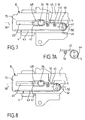
- la figure 6 est une coupe suivant le plan VI-VI de la figure 4 ;
- les figures 7, 7A et 8 sont des vues analogues à la figure 4 de variantes de réalisation,
- les figures 9, 10, 11 et 12 sont des vues analogues à la figure 4, des variantes d'une autre architecture de l'invention.
- Figure 1 is a side view along the axis of direction of a steering column in which is mounted the energy absorbing device according to the invention;
- Figure 2 is a top perspective view of the entire energy absorbing device according to the invention; the assembly being in the normal driving position before an impact;
- Figure 3 is a view similar to Figure 2 of the complete device;
- Figure 4 is a top view of Figure 2 of another embodiment;
- Figure 4A is a detail view of Figure 4 of an alternative embodiment;
- Figure 5 is a section along the plane VV of Figure 4;
- Figure 6 is a section along the plane VI-VI of Figure 4;
- FIGS. 7, 7A and 8 are views similar to FIG. 4 of variant embodiments,
- Figures 9, 10, 11 and 12 are views similar to Figure 4, variants of another architecture of the invention.
Comme on peut le voir sur la figure 1, la colonne de direction de véhicule automobile comprend un arbre de direction 1 qui est monté tournant dans un tube-corps 2 autour d'un axe de direction 3. Le tube-corps 2 est relié à un ensemble support 6 par un système de réglage en position en profondeur ou en inclinaison, ou par un système de réglage en profondeur et en inclinaison. L'invention peut s'appliquer également à une colonne de direction non réglage, dans ce cas le tube-corps 2 est relié directement à l'ensemble support 6.As can be seen in Figure 1, the steering column of a motor vehicle comprises a steering shaft 1 which is rotatably mounted in a tube-
L'ensemble support 6 comprend un élément support fixe 8 et un élément support mobile 9. L'élément support fixe 8 est solidaire du châssis du véhicule ou d'un élément de carrosserie. L'élément support mobile 9 est relié au tube-corps 2 par le système de réglage en position. L'élément support mobile 9 est relié à l'élément support fixe 8, et ledit élément support mobile 9 est bloqué sur ledit élément support fixe à une valeur déterminée, qui tient compte du choc à absorber afin de permettre dans ce cas à l'élément support mobile 9 de coulisser dans l'élément support fixe 8.The
L'ensemble support 6 est l'ensemble de fixation supérieure de la colonne de direction. Un ensemble de fixation inférieure de la colonne de direction comporte un axe d'articulation horizontal, qui permet le réglage en hauteur de ladite colonne.The
On appellera plan vertical : un plan qui est parallèle au plan vertical passant par l'axe de direction.Vertical plane will be called a plane that is parallel to the vertical plane passing through the axis of direction.
Comme cela est représenté notamment sur les figures 2 et 3, l'élément support fixe 8 comporte une embase 15 avec un montant 13 et un montant 14 à chacune de ses extrémités transversales ; les montants 13 et 14 étant sensiblement verticaux et perpendiculaires à l'embase 15.As shown in particular in Figures 2 and 3, the fixed
Dans la suite de la description, on appellera arrière le côté du volant de direction, et avant le côté opposé c'est-à-dire celui du boîtier de direction situé du côté de l'avant du véhicule. On appellera gauche et droite ce qui est à la gauche ou à la droite du conducteur.In the following description, we will call back the side of the steering wheel, and before the opposite side that is to say that of the steering box located on the front side of the vehicle. We will call left and right what is to the left or right of the driver.
Chaque montant 13 et 14 de l'élément support fixe 8 comporte à l'arrière un élément latéral 17 muni d'un trou de fixation 19. Chaque montant 13 et 14 comporte à l'avant un élément latéral 16 muni d'un trou de fixation 18 recevant une vis de fixation dans la structure du véhicule.Each
L'élément support mobile 9 comporte un élément de raccordement 23 avec un montant 21 et un montant 22 à chacune de ses extrémités transversales, les montants 21 et 22 étant sensiblement verticaux et perpendiculaires à l'élément de raccordement 23.The
L'élément support mobile 9 est disposé entre les montants 13 et 14 de l'élément support fixe 8. L'élément de raccordement 23 est sensiblement parallèle à l'embase 15, et les deux montants 21 et 22 sont guidés, et coulissent, en cas de choc, entre les deux montants 13 et 14 de l'élément support fixe 8.The
Les montants 13 et 14 ainsi que les montants 21 et 22 sont orientés selon la direction du déplacement en cas de choc de l'élément support mobile 9.The
Chaque montant 21 et 22 de l'élément support mobile 9 comporte à l'arrière un élément latéral 24 muni d'un trou oblong débouchant 25. Chaque élément latéral 24 avec le trou oblong débouchant 25 s'applique contre l'élément latéral 17 avec le trou de fixation 19 correspondant de l'élément support fixe 8.Each
Chaque groupe d'un trou de fixation 19 et d'un trou oblong débouchant 25 reçoit une vis de fixation dans la structure du véhicule. Une capsule de récupération d'énergie peut être disposée entre chaque élément latéral 17 et l'élément latéral 24 correspondant.Each group of a fixing
Un trou oblong de guidage 20 d'axe 30 est agencé dans l'embase 15. L'axe 30 et les bords latéraux du trou oblong 20 sont sensiblement parallèles aux montants 13 et 14 de l'élément support fixe 8.An axis guide
Un élément d'accrochage 26 est fixé sur l'élément de raccordement 23 de l'élément support mobile 9, et il traverse le trou oblong de guidage 20. L'élément d'accrochage 26 est dimensionné pour coulisser dans le trou oblong de guidage 20. Ledit trou oblong de guidage 20 doit avoir une longueur axiale suffisante pour permettre le déplacement de l'élément d'accrochage 26 de l'élément support mobile 9, en cas de choc.A hooking
L'élément support fixe 8 et lélément support mobile 9 sont raccordés en un troisième point, en plus des deux points des deux groupes de trous 19 et 25.The fixed
Le troisième point est matérialisé par un ensemble de liaison 11, qui est représenté sur les figures d'ensemble 2, 3 et 4 et sur la coupe axiale de la figure 6. Comme cela est représenté sur la figure 6, l'ensemble de liaison 11 comporte deux rondelles plastique 31 et 32, une rondelle métallique 33 et une vis de fixation 38 qui ont un même axe disposé dans le plan vertical de l'axe 30 et perpendiculaire à l'embase 15. Tout en restant dans le cadre de l'invention, il peut y avoir d'autre point de guidage de la colonne lors de son déplacement.The third point is materialized by a
La première rondelle plastique 31 est disposée entre l'embase 15 de l'élément support fixe 8 et l'élément de raccordement 23 de l'élément support mobile 9. La deuxième rondelle plastique 32 est disposée de l'autre côté de l'embase 15, et elle est munie d'un tenon cylindrique 34 qui traverse et coulisse dans le trou oblong de guidage 20 en cas de choc. Le tenon cylindrique 34 s'engage dans un trou 35 de la première rondelle plastique 31.The first
La rondelle métallique 33 est placée sur la deuxième rondelle plastique 32. La rondelle métallique 33, et le tenon cylindrique 34 ont respectivement un trou de passage 37 et 36, qui reçoivent un élément de fixation du type vis de fixation 38, qui s'applique contre la rondelle métallique 33 et qui se fixe dans un trou de fixation 27 de l'élément de raccordement 23.The
La vis de fixation 38 relie la rondelle métallique 33 à l'élément de raccordement 23, afin d'avoir le serrage voulu des deux rondelles plastique 31 et 32 sur l'embase 15, pour permettre le coulissement de l'élément support mobile 9 en cas de choc.The
Selon l'invention, le dispositif d'absorption d'énergie comporte un fil métallique unique 4 et un générateur d'effort 7 comme cela est représenté sur les figures 2, 4 et 7 à 12.According to the invention, the energy absorbing device comprises a
Le fil métallique unique 4 comprend une première portion 41, une deuxième portion 42 et une troisième portion 43 ou 44 suivant sa forme. La première portion 41 a une première extrémité 45 et une deuxième extrémité 46, et la deuxième portion 42 a une deuxième extrémité 49.The
La première portion 41 est sensiblement rectiligne avec sa première extrémité 45 qui est raccordée à l'élément support mobile 9. La deuxième extrémité 46 se prolonge par la première extrémité de la deuxième portion 42.The
La deuxième portion 42 a sa deuxième extrémité 49 qui se prolonge par la troisième portion 43 ou 44. La deuxième portion 42 s'applique contre un rouleau 5 relié à l'élément support fixe 8, afin que la deuxième portion 42 soit déformée selon une forme demi-circulaire, qui se prolonge par la troisième portion 43 ou 44 dont l'extrémité est libre.The
Le générateur d'effort 7 est relié à l'élément support fixe 8. Ledit générateur d'effort 7 est disposé d'un côté de la portion de fil métallique 4 concerné ; et il est capable de fournir un effort variable afin de déformer le fil métallique 4 suivant une direction transversale audit fil. Cette action a lieu en dehors de la deuxième portion 42 de forme demi-circulaire et elle s'effectue selon une direction sensiblement perpendiculaire au fil métallique 4. Le générateur d'effort 7 agit entre deux éléments d'appui 10, qui sont reliés à l'élément support fixe 8 et qui sont disposés de l'autre côté de la portion 41 ou 43 de fil concerné.The
L'architecture de l'invention permet ainsi d'avoir un dispositif d'absorption d'énergie infiniment modulable qui s'adapte à chaque cas de choc. De plus, le générateur d'effort 7 peut avoir différentes réalisations et notamment une réalisation pyrotechnique.The architecture of the invention thus makes it possible to have an infinitely scalable energy absorption device that adapts to each case of shock. In addition, the
Comme cela est représenté notamment sur les figures 4, 5 et 7, la première extrémité 45 de la première portion 41 du fil métallique 4 est relié à l'élément d'accrochage 26 de l'élément de raccordement 23, qui coulisse dans le trou oblong de guidage 20 de l'embase 15.As shown in particular in Figures 4, 5 and 7, the
La première extrémité 45 de la première portion 41 du fil 4 est conforme pour obtenir une boucle ou crochet 47, qui entoure complètement l'élément d'accrochage 26.The
Le crochet 47 a un logement 48 qui a une longueur axiale plus grande que la longueur axiale de l'élément d'accrochage 26.The
Cette différence de longueur permet d'avoir une course en cas de choc, qui s'effectue avant l'entrée en action du dispositif d'absorption d'énergie de l'invention, qui opère avec un certain retard prédéterminé.This difference in length makes it possible to have a stroke in the event of an impact, which occurs before the energy absorption device of the invention enters into action, which operates with a certain predetermined delay.
Comme cela est représenté sur la figure 4A, le rouleau 5 est fixé sur l'embase 15. Il est constitué par un grand rouleau 51 entouré d'une couronne plastique 52. Le grand rouleau 51 est fixé sur l'embase 15 et il comporte un pion de centrage 56 et un trou 53 pour une vis de fixation 54 dans le rouleau 5.As shown in FIG. 4A, the
Comme cela est représenté sur la figure 5, chaque élément d'appui 10, qui est indépendant, est monté sur l'embase 15. Chaque élément d'appui 10 indépendant est constitué par un petit rouleau 57, qui est entouré d'une couronne plastique 58. Le petit rouleau 57 est monté sur un axe 59 qui est fixé à l'embase 15.As shown in FIG. 5, each bearing
Le dispositif de l'invention comporte enfin une plaque de fermeture 12 qui permet de maintenir le dispositif en place lors du transport et lors du montage dans le véhicule, elle permet également le guidage du fil métallique 4 lors du choc.The device of the invention finally comprises a
La plaque de fermeture 12 comporte une embase 63 qui recouvre le fil métallique 4, le rouleau 5, les éléments d'appui 10, l'ensemble de liaison 11 et l'embase 15 de l'élément support fixe 8. L'embase 63 est munie à chacune de ses extrémités transversales d'un montant 61 et d'un montant 62, qui sont perpendiculaires à l'embase 63 et qui entourent les montants 13 et 14 de l'élément support fixe 8. Chaque montant 61 et 62 est muni d'un élément latéral 64, qui s'applique contre l'élément latéral 16 de l'élément support fixe 8. Chaque groupe de deux éléments latéraux 61-16 et 62-16 est muni chacun d'un trou de fixation 65 et 18 qui reçoit une vis de fixation dans la structure du véhicule. Pour le transport et le montage sur véhicule, la plaque de fermeture 12 est mise en place par le pion de centrage 56, et par le ou les axes 59 du ou des petits rouleaux 57 d'appui. La plaque de fermeture 12 est fixée sur l'embase 15 par la vis de fixation 54 du rouleau 5.The
De plus, la plaque de fermeture 12 comporte un élément de frottement 66 muni d'un organe d'accrochage 67, qui se monte sur l'un des deux montants 61 ou 62. Le fil métallique 4 peut ainsi coulisser entre l'élément de frottement 66 et être ainsi guidé.In addition, the
La plaque de fermeture vient couvrir le mécanisme d'absorption d'énergie. Elle sert également comme support ou guide pour le brin libre du fil métallique 4 afin d'éviter qu'il se déforme lors du choc.The closure plate covers the energy absorption mechanism. It also serves as a support or guide for the free end of the
En situation normale de conduite, la partie mobile en cas de choc de la colonne est liée à la partie fixe de celle-ci par l'intermédiaire des deux capsules et du troisième point situé dans l'axe de la colonne. Un retard au déplacement est aménagé entre la boucle du fil métallique 4 et la partie mobile de la colonne, pour permettre lors d'un choc, la rupture des capsules sans efforts supplémentaires.In normal driving situation, the moving part in case of shock of the column is linked to the fixed part thereof through the two capsules and the third point located in the axis of the column. A delay in displacement is arranged between the loop of the
En dehors de la situation de choc, le doigt du générateur d'effort 7 est rentré, et aucun effort de poussée n'est appliqué sur le fil métallique dans cette condition. Ceci est également vrai dans le cas d'un choc peu énergétique, qui ne nécessite pas le fonctionnement du générateur d'effort 7, ou également dans le cas de non fonctionnement de ce dernier. Dans ces deux dernières conditions, une absorption d'énergie minimale est assurée sur la colonne de direction. Elle est donnée par la loi de comportement du fil métallique, selon son implantation sur la colonne.Outside the shock situation, the finger of the
En revanche, lors d'un choc sévère, l'unité électronique de commande reçoit les informations provenant des différents capteurs placés sur le véhicule (vitesse du véhicule immédiatement avant le choc, poids du conducteur, port de la ceinture de sécurité, etc...), nécessaires pour le calcul de la loi de commande du générateur d'effort 7. Selon la loi de commande élaborée par l'unité électronique, le générateur d'effort 7 exerce un effort latéral plus ou moins important sur le fil, pour freiner son déplacement, et adapter par conséquent, la quantité d'énergie absorbée par la colonne de direction à la situation du choc. Le différentiel d'énergie obtenu par la poussée du générateur d'effort 7 provient de la combinaison de deux phénomènes, de déformation et de frottement du fil entre le doigt du générateur d'effort 7 et les éléments d'appui 10.On the other hand, during a severe shock, the electronic control unit receives the information from the various sensors placed on the vehicle (speed of the vehicle immediately before the impact, weight of the driver, wearing of the seat belt). safety, etc ...), necessary for the calculation of the control law of the
La modulation de l'effort d'absorption peut alors être infiniment variable en fonction des lois de commande élaborées par l'électronique, qui tient compte des valeurs spécifiques des différents paramètres associés au choc.The modulation of the absorption force can then be infinitely variable depending on the control laws developed by the electronics, which takes into account the specific values of the various parameters associated with the shock.
L'électronique calcule la loi de commande du générateur d'effort 7 en tenant compte de la course totale de rétraction aménagée sur la colonne. L'énergie de choc est alors répartie sur toute la course disponible sur la colonne, pour réduire le niveau d'effort appliqué sur le corps du conducteur, et réduire par conséquent les risques de blessures.The electronics calculates the control law of the
Le dispositif de l'invention est très souple et il permet tous les types d'agencement. Ainsi, le rouleau 5 peut être disposé à gauche de l'axe 30 du trou oblong de guidage 20 comme sur les figures 2 à 8. Le rouleau 5 peut également être disposé à droite de l'axe 30 du trou oblong de guidage comme sur les figures 9 à 12.The device of the invention is very flexible and it allows all types of arrangement. Thus, the
Dans les deux configurations ci-dessus du rouleau 5, le générateur d'effort 7 peut s'appliquer sur la troisième portion 43 du fil métallique 4 qui est sensiblement rectiligne, comme sur les figures 1 à 6 et 9 et 10.In the above two configurations of the
Dans les deux configurations du rouleau 5, le générateur d'effort 7 peut s'appliquer sur la première portion 41 du fil métallique 4, comme c'est le cas des figures 7, 7A, 8, 11 et 12.In both configurations of the
Dans ces derniers types de montage, la troisième portion 43 du fil métallique 4 peut être sensiblement rectiligne, comme c'est le cas des figures 1 à 7 et 8 à 12, ou la troisième portion 44 du fil métallique 4 est enroulée autour du rouleau 5, comme c'est le cas de la figure 7A.In these latter types of mounting, the
Les deux appuis 10 peuvent avoir plusieurs types de réalisations.The two
Dans un premier type de réalisation, le générateur d'effort 7 agit entre deux éléments d'appui indépendants 10, comme sur les figures 2, 3, 7, 9 et 11.In a first type of embodiment, the
Dans un deuxième type de réalisation, le générateur d'effort 7 agit entre un élément d'appui indépendant 10 et un élément d'appui intégré 55 au rouleau 5, comme c'est le cas de la figure 4A.In a second type of embodiment, the
Dans un troisième type de réalisation, le générateur d'effort agit entre un élément d'appui indépendant 10 et un élément d'appui constitué par le rouleau 5, comme sur les figures 4, 7A, 8, 10 et 12.In a third embodiment, the force generator acts between an
Claims (16)
- A device for the absorption of energy of an automotive vehicle steering column including a steering shaft(1) with a steering wheel rotatably mounted about an steering axis (3) in a tubular body (52), said steering column being mounted in a support system (6) including a fixed support element (8) and a movable support element (9), in case of impact, device in which:- the fixed support member (8) includes a base (15) having two substantially vertical side walls (13, 14) ;- the movable support member (9) includes two substantially vertical side walls (21, 22) connected by a connection element (23) substantially parallel to the base (15), said side walls (21, 22) are arranged and guided between the two side walls (13, 14) of the fixed support (8) in case of impact ;- the side walls (13, 14, 21, 22) are oriented along the direction of displacement of the movable support element (9) in case of impact ;- a single metallic wire (4) is disposed outside and against the base (15) of the fixed support (8), said wire including:a first substantially straight portion (41) whose end (45) is connected to the movable support element (9) and whose other end (46) is extended bya second portion (42) that is applied against a cylinder (5) linked to the base (15) of the fixed support element (8), whereby the second portion (42) is deformed in a semicircular manner and is extended by. a third wire portion (43, 44) whose end is free ;- an oblong guide hole (20) arranged in the base (15) extends substantially parallel to the side walls (13, 14) and has a length permitting the displacement of the movable support element (9) ;- a hitching element (26) of the metallic wire (4) is attached to the connection element (23) and extends through the oblong guide hole (20) so as to be linked to the end (45) of the first portion (41) of the metallic wire (4), said hitching element (26) being arranged to slide in the oblong guide hole (20) ;- a force generator (7) connected with the fixed support element (8) is arranged on one side of the portion of the wire (4) concerned and can supply a variable force so as to deform the metallic wire (4) along a direction transverse to said wire apart from the second portion (42) with a semicircular shape ;- said force generator (7) operating between two support members (10) mounted on the base (15) of the fixed support element (8) and arranged on the other side of the wire portion concerned ;- thereby to provide an infinitely modulatable energy absorption device that adapts to each impact situation.
- An energy absorption device as claimed in claim 1, characterized in that the force generator (7) operates on the third portion (43) of the metallic wire (4) which is substantially straight.
- An energy absorption device as claimed in claim 1, characterized in that the force generator (7) operates on the first portion (41) of the metallic wire (4).
- An energy absorption device as claimed in claim 3, characterized in that the third portion (43) of the metallic wire (4) is substantially straight.
- An energy absorption device as claimed in claim 3, characterized in that the third portion (44) of the metallic wire (4) is rolled up around the cylinder (5).
- An energy absorption device as claimed in one of claims 2 and 3, characterized in that the force generator (7) operates between two independent support members (10).
- An energy absorption device as claimed in one of claims 2 and 3, characterized in that the force generator (7) operates between an independent support member (10) and a support member (55) integrated into the cylinder (5).
- An energy absorption device as claimed in one of claims 2 and 3, characterized in that the force generator (7) operates between an independent support member (10) and a support member made up of the cylinder (5).
- An energy absorption device as claimed in any one of previous claims, characterized in that- each side wall (13, 14) of the fixed support element (8) includes a lateral element (17) equipped with a fastening hole (19) ;- each side wall (21, 22) of the movable support element (9) comprises a lateral element (24) with an oblong outlet hole (25), which is applied against the lateral element (17) and the corresponding mounting hole (19) of the fixed support element (8), the two mounting holes (19) and the two oblong holes (25) receiving a fastening element of the vehicle structure;- the fixed support element (8) and the movable support element (9) are linked by a connection assembly (11) which comprises :. a metallic washer (31), arranged between the base (15) and the connection element (23), receives a cylindrical sleeve portion (34) of a second synthetic plastic washer (32) arranged on the other side of the base (15), the cylindrical sleeve portion (34) extending through and sliding within the oblong guide hole (20) ;. a metallic washer (33) placed on the second plastic washer (32) ; and. a fastening element (38) connecting the metallic washer (33) to the connecting element (23) so as to obtain the desired tightening to make it possible for the movable support element(9) to slide in case of impact.
- An energy absorption device as claimed in claim 9, characterized in that the cylinder (5) is arranged to the left of the axis (30) of the oblong guide hole (20).
- An energy absorption device as claimed in claim 9, characterized in that the cylinder (5) is arranged to the right of the axis (30) of the oblong guide hole (20).
- An energy absorption device as claimed in claim 9, characterized in that the end (45) of the first portion (41) of the wire (4) is so shaped as to define a hook (47) completely surrounding the hitching element (26) ; the axial length of the housing (48) of the hook (47) being greater than the axial length of the hitching element (26), thereby to provide a delay in the action of the energy absorption device in case of impact.
- An energy absorption device as claimed in claim 9, characterized in that:- each independent support member (10) is a small cylinder (57) surrounded by a plastic sleeve (58) and is mounted on an axle (59) fixed upon the base (15) ; and- the cylinder (5) is surrounded by a synthetic plastic sleeve (52) and comprises a centering pin (56).
- An energy absorption device as claimed in claim 9, characterized in that it includes a cover plate (12) which consists of a base (63) that covers the metallic wire (4) and the base (15) of the fixed support element (8), as well as two side walls (61, 62) that surround the side walls (13, 14) of the fixed support element (8), each side wall (61, 62) is equipped with a lateral element (64) that is applied against a corresponding lateral element (16) of the fixed support element (8), each group of two lateral elements (61,16-62,16) being each equipped with a fixation hole receiving a fixation element in the vehicle structure, said cover plate (12) being mounted in place by the centering pin (56), and by the axle or axles (59) of the small support cylinder (57), and being fixed upon the base (15) by the mounting screw (54) of the cylinder (5).
- An energy absorption device as claimed in claim 14, characterized in that the metallic wire (4) slides against a friction element (66) which is hooked onto one of the two side walls of the cover plate (12).
- An energy absorption device as claimed in any one of previous claims, characterized in that the force generator (7) is a pyrotechnic force generator.
Applications Claiming Priority (2)
| Application Number | Priority Date | Filing Date | Title |
|---|---|---|---|
| FR0308431 | 2003-07-10 | ||
| FR0308431A FR2857322B1 (en) | 2003-07-10 | 2003-07-10 | INFINITELY MODULAR ENERGY ABSORPTION DEVICE OF A MOTOR VEHICLE STEERING COLUMN |
Publications (2)
| Publication Number | Publication Date |
|---|---|
| EP1495940A1 EP1495940A1 (en) | 2005-01-12 |
| EP1495940B1 true EP1495940B1 (en) | 2007-12-26 |
Family
ID=33443255
Family Applications (1)
| Application Number | Title | Priority Date | Filing Date |
|---|---|---|---|
| EP04015325A Not-in-force EP1495940B1 (en) | 2003-07-10 | 2004-06-30 | Infinitely adjustable energy absorbing device for a motor vehicle steering column |
Country Status (5)
| Country | Link |
|---|---|
| US (1) | US7156420B2 (en) |
| EP (1) | EP1495940B1 (en) |
| AT (1) | ATE382010T1 (en) |
| DE (1) | DE602004010868T2 (en) |
| FR (1) | FR2857322B1 (en) |
Cited By (1)
| Publication number | Priority date | Publication date | Assignee | Title |
|---|---|---|---|---|
| CN102958781A (en) * | 2010-11-15 | 2013-03-06 | 日本精工株式会社 | Support device for steering column |
Families Citing this family (14)
| Publication number | Priority date | Publication date | Assignee | Title |
|---|---|---|---|---|
| US6942250B2 (en) * | 2003-05-02 | 2005-09-13 | Delphi Technologies, Inc. | Energy absorber for motor vehicle steering column |
| US6916044B2 (en) * | 2003-07-08 | 2005-07-12 | Daimlerchrysler Corporation | Steering column/airbag tunable impact absorption system |
| GB0525850D0 (en) * | 2005-09-01 | 2006-02-01 | Trw Lucasvarity Electric Steer | A Steering Column Assembly |
| US7780196B2 (en) * | 2006-10-05 | 2010-08-24 | Gm Global Technology Operations, Inc. | Energy absorbing steering column assembly |
| US7661711B2 (en) * | 2006-10-26 | 2010-02-16 | Gm Global Technology Operations, Inc. | Steering column assembly with active energy absorption device |
| US7709239B2 (en) * | 2006-12-07 | 2010-05-04 | E.I. Du Pont De Nemours And Company | Mutant Δ8 desaturase genes engineered by targeted mutagenesis and their use in making polyunsaturated fatty acids |
| KR101065895B1 (en) * | 2007-03-30 | 2011-09-19 | 주식회사 만도 | Steering Column for Motor Vehicle Having Collision Energy Absorbing Apparatus |
| KR101115084B1 (en) * | 2008-02-29 | 2012-02-28 | 주식회사 만도 | The Collision Energy Absorbable Steering Column for Vehicle |
| US7896395B2 (en) * | 2008-08-05 | 2011-03-01 | Nexteer (Beijing) Technology Co., Ltd. | Steering column having an actuator for applying a resultant force |
| US8540280B2 (en) * | 2011-03-18 | 2013-09-24 | Nsk Ltd. | Steering apparatus |
| JP2013001242A (en) * | 2011-06-16 | 2013-01-07 | Jtekt Corp | Steering apparatus |
| MX2017003713A (en) * | 2014-09-22 | 2017-06-28 | Nsk Americas Inc | Improved energy absorption module for vehicle steering column assembly. |
| EP3187393B1 (en) * | 2015-10-23 | 2019-05-08 | FUJI KIKO Co., Ltd. | Steering column apparatus |
| FR3079274B1 (en) * | 2018-03-26 | 2020-03-13 | Robert Bosch Automotive Steering Vendome | MODULAR ENERGY ABSORPTION DEVICE |
Family Cites Families (9)
| Publication number | Priority date | Publication date | Assignee | Title |
|---|---|---|---|---|
| US5605352A (en) * | 1995-12-08 | 1997-02-25 | General Motors Corporation | Energy absorbing steering column |
| US5961146A (en) * | 1996-01-18 | 1999-10-05 | Nsk Ltd. | Shock absorbing type steering column assembly |
| FR2775648B3 (en) * | 1998-03-03 | 2000-05-12 | Lemforder Nacam Sa | ENERGY ABSORBING DEVICE WITH DOUBLE SPIRAL WINDING FOR STEERING COLUMN OF MOTOR VEHICLE |
| FR2788029B1 (en) * | 1999-01-06 | 2001-02-23 | Lemforder Nacam Sa | MODULAR ENERGY ABSORPTION DEVICE FROM A AUTOMOTIVE VEHICLE STEERING COLUMN |
| DE60006815T2 (en) * | 1999-06-11 | 2004-05-27 | Delphi Technologies, Inc., Troy | ENERGY SENSOR FOR VEHICLE STEERING COLUMN |
| DE10039792A1 (en) * | 2000-08-16 | 2002-02-28 | Daimler Chrysler Ag | Steering column for a motor vehicle |
| JP3900924B2 (en) * | 2001-04-03 | 2007-04-04 | トヨタ自動車株式会社 | Steering device support mechanism |
| DE60223590T2 (en) * | 2001-11-30 | 2008-09-18 | Delphi Technologies, Inc., Troy | REACTION ENERGY ACQUISITION SYSTEM |
| US6799486B2 (en) * | 2002-06-07 | 2004-10-05 | Delphi Technologies, Inc. | Interactive energy absorbing system |
-
2003
- 2003-07-10 FR FR0308431A patent/FR2857322B1/en not_active Expired - Fee Related
-
2004
- 2004-06-30 AT AT04015325T patent/ATE382010T1/en not_active IP Right Cessation
- 2004-06-30 DE DE602004010868T patent/DE602004010868T2/en active Active
- 2004-06-30 EP EP04015325A patent/EP1495940B1/en not_active Not-in-force
- 2004-07-09 US US10/886,653 patent/US7156420B2/en not_active Expired - Fee Related
Cited By (2)
| Publication number | Priority date | Publication date | Assignee | Title |
|---|---|---|---|---|
| CN102958781A (en) * | 2010-11-15 | 2013-03-06 | 日本精工株式会社 | Support device for steering column |
| CN102958781B (en) * | 2010-11-15 | 2015-04-08 | 日本精工株式会社 | Support device for steering column |
Also Published As
| Publication number | Publication date |
|---|---|
| ATE382010T1 (en) | 2008-01-15 |
| US20050012316A1 (en) | 2005-01-20 |
| US7156420B2 (en) | 2007-01-02 |
| DE602004010868D1 (en) | 2008-02-07 |
| DE602004010868T2 (en) | 2009-01-02 |
| EP1495940A1 (en) | 2005-01-12 |
| FR2857322A1 (en) | 2005-01-14 |
| FR2857322B1 (en) | 2006-08-11 |
Similar Documents
| Publication | Publication Date | Title |
|---|---|---|
| EP1495940B1 (en) | Infinitely adjustable energy absorbing device for a motor vehicle steering column | |
| EP1176082B1 (en) | Pyrotechnically adjustable energy absorbing device along the axis of a motor vehicle steering column | |
| EP1479593B1 (en) | Vehicle steering column with adjustable energy absorbing means and pyrotechnic actuators | |
| EP1018463B1 (en) | Adjustable motor vehicle steering column energy absorbing mechanism | |
| EP0662415B1 (en) | Energy absorbing device with axial guide for the steering column of a motor vehicle | |
| EP0755844B1 (en) | Energy absorbing and guiding device for the steering column of a motor vehicle | |
| FR2736312A1 (en) | BACKREST FOR VEHICLE SEAT AND SEAT COMPRISING SUCH A BACKREST | |
| FR2667038A1 (en) | STEERING SUPPORT STRUCTURE FOR MOTOR VEHICLE. | |
| FR2801269A1 (en) | MODULAR ENERGY ABSORPTION DEVICE WITH PYROTECHNIC LOADS FROM A STEERING COLUMN OF A MOTOR VEHICLE | |
| EP1805063B1 (en) | Kart which is equipped with a protective assembly comprising a lateral sliding element, and corresponding lateral element and protective assembly | |
| FR2805512A1 (en) | DEVICE FOR LINEAR GUIDANCE OF A STEERING COLUMN | |
| EP1375298B1 (en) | Motor vehicle steering column energy absorption device | |
| FR2781189A1 (en) | Protective device for vehicle driver is fitted with mechanism designed to displace instrument panel upwards and steering column forwards under shock load conditions | |
| EP0089879B1 (en) | Fast locking and unlocking safety belt retractor with reduced operating noise | |
| FR2862034A1 (en) | Passenger restraint system for motor vehicle, has sheet metal section mounting seat belt retractor on upper section of backrest of rear seat, in zone of inner wall of vehicle, so that safety belt is directly retracted by passenger | |
| EP0532378B1 (en) | Restraining device for the back-seat middle passenger of a vehicle | |
| FR2872474A1 (en) | Energy absorbing device for steering column of motor vehicle, has stress generator with reciprocating finger acting on rectilinear portions of metal strap to deform strap between fixed support units for arranging device in two zones | |
| EP2440728A1 (en) | Handle of an openable body section of an automobile | |
| FR2493155A1 (en) | SEAT BELT DEVICE FOR MOTOR VEHICLES | |
| FR2863298A1 (en) | Hood lock for use in motor vehicle, has cam with end that cooperates with edge of bolt when bolt is turned under effect of force exerted by strike plate wire, and leaf spring that tends to turn cam to slow down rotation of bolt | |
| FR2887189A1 (en) | Centrifugal force effect compensating device for e.g. race vehicle, has cradles connected to seat support of seat by pivots, and steering wheel connected to support by lateral arm | |
| WO2010146271A1 (en) | Device for protecting the foot of a vehicle driver in the event of frontal impact | |
| EP1479592A1 (en) | Device with deformable metallic inserts of a motor vehicle steering column energy absorption system | |
| WO2017089316A1 (en) | Motor vehicle comprising an element for protecting the driver's head | |
| FR3084858A1 (en) | VEHICLE SEAT WITH BACK UP BACK IN CASE OF FRONT SHOCK |
Legal Events
| Date | Code | Title | Description |
|---|---|---|---|
| PUAI | Public reference made under article 153(3) epc to a published international application that has entered the european phase |
Free format text: ORIGINAL CODE: 0009012 |
|
| AK | Designated contracting states |
Kind code of ref document: A1 Designated state(s): AT BE BG CH CY CZ DE DK EE ES FI FR GB GR HU IE IT LI LU MC NL PL PT RO SE SI SK TR |
|
| AX | Request for extension of the european patent |
Extension state: AL HR LT LV MK |
|
| 17P | Request for examination filed |
Effective date: 20050129 |
|
| AKX | Designation fees paid |
Designated state(s): AT BE BG CH CY CZ DE DK EE ES FI FR GB GR HU IE IT LI LU MC NL PL PT RO SE SI SK TR |
|
| 17Q | First examination report despatched |
Effective date: 20060725 |
|
| GRAP | Despatch of communication of intention to grant a patent |
Free format text: ORIGINAL CODE: EPIDOSNIGR1 |
|
| RIN1 | Information on inventor provided before grant (corrected) |
Inventor name: BEN RHOUMA, ABDEL KARIM Inventor name: EYMERY, VINCENT Inventor name: LAISEMENT, ANDRE |
|
| GRAS | Grant fee paid |
Free format text: ORIGINAL CODE: EPIDOSNIGR3 |
|
| GRAA | (expected) grant |
Free format text: ORIGINAL CODE: 0009210 |
|
| AK | Designated contracting states |
Kind code of ref document: B1 Designated state(s): AT BE BG CH CY CZ DE DK EE ES FI FR GB GR HU IE IT LI LU MC NL PL PT RO SE SI SK TR |
|
| REG | Reference to a national code |
Ref country code: GB Ref legal event code: FG4D Free format text: NOT ENGLISH |
|
| REG | Reference to a national code |
Ref country code: IE Ref legal event code: FG4D Free format text: LANGUAGE OF EP DOCUMENT: FRENCH |
|
| REG | Reference to a national code |
Ref country code: CH Ref legal event code: EP |
|
| REF | Corresponds to: |
Ref document number: 602004010868 Country of ref document: DE Date of ref document: 20080207 Kind code of ref document: P |
|
| GBT | Gb: translation of ep patent filed (gb section 77(6)(a)/1977) |
Effective date: 20080225 |
|
| PG25 | Lapsed in a contracting state [announced via postgrant information from national office to epo] |
Ref country code: SE Free format text: LAPSE BECAUSE OF FAILURE TO SUBMIT A TRANSLATION OF THE DESCRIPTION OR TO PAY THE FEE WITHIN THE PRESCRIBED TIME-LIMIT Effective date: 20080326 |
|
| PG25 | Lapsed in a contracting state [announced via postgrant information from national office to epo] |
Ref country code: PL Free format text: LAPSE BECAUSE OF FAILURE TO SUBMIT A TRANSLATION OF THE DESCRIPTION OR TO PAY THE FEE WITHIN THE PRESCRIBED TIME-LIMIT Effective date: 20071226 Ref country code: NL Free format text: LAPSE BECAUSE OF FAILURE TO SUBMIT A TRANSLATION OF THE DESCRIPTION OR TO PAY THE FEE WITHIN THE PRESCRIBED TIME-LIMIT Effective date: 20071226 Ref country code: SI Free format text: LAPSE BECAUSE OF FAILURE TO SUBMIT A TRANSLATION OF THE DESCRIPTION OR TO PAY THE FEE WITHIN THE PRESCRIBED TIME-LIMIT Effective date: 20071226 Ref country code: FI Free format text: LAPSE BECAUSE OF FAILURE TO SUBMIT A TRANSLATION OF THE DESCRIPTION OR TO PAY THE FEE WITHIN THE PRESCRIBED TIME-LIMIT Effective date: 20071226 |
|
| NLV1 | Nl: lapsed or annulled due to failure to fulfill the requirements of art. 29p and 29m of the patents act | ||
| PG25 | Lapsed in a contracting state [announced via postgrant information from national office to epo] |
Ref country code: AT Free format text: LAPSE BECAUSE OF FAILURE TO SUBMIT A TRANSLATION OF THE DESCRIPTION OR TO PAY THE FEE WITHIN THE PRESCRIBED TIME-LIMIT Effective date: 20071226 |
|
| PG25 | Lapsed in a contracting state [announced via postgrant information from national office to epo] |
Ref country code: ES Free format text: LAPSE BECAUSE OF FAILURE TO SUBMIT A TRANSLATION OF THE DESCRIPTION OR TO PAY THE FEE WITHIN THE PRESCRIBED TIME-LIMIT Effective date: 20080406 Ref country code: CZ Free format text: LAPSE BECAUSE OF FAILURE TO SUBMIT A TRANSLATION OF THE DESCRIPTION OR TO PAY THE FEE WITHIN THE PRESCRIBED TIME-LIMIT Effective date: 20071226 |
|
| PG25 | Lapsed in a contracting state [announced via postgrant information from national office to epo] |
Ref country code: RO Free format text: LAPSE BECAUSE OF FAILURE TO SUBMIT A TRANSLATION OF THE DESCRIPTION OR TO PAY THE FEE WITHIN THE PRESCRIBED TIME-LIMIT Effective date: 20071226 Ref country code: SK Free format text: LAPSE BECAUSE OF FAILURE TO SUBMIT A TRANSLATION OF THE DESCRIPTION OR TO PAY THE FEE WITHIN THE PRESCRIBED TIME-LIMIT Effective date: 20071226 |
|
| PG25 | Lapsed in a contracting state [announced via postgrant information from national office to epo] |
Ref country code: PT Free format text: LAPSE BECAUSE OF FAILURE TO SUBMIT A TRANSLATION OF THE DESCRIPTION OR TO PAY THE FEE WITHIN THE PRESCRIBED TIME-LIMIT Effective date: 20080526 |
|
| REG | Reference to a national code |
Ref country code: IE Ref legal event code: FD4D |
|
| PG25 | Lapsed in a contracting state [announced via postgrant information from national office to epo] |
Ref country code: IE Free format text: LAPSE BECAUSE OF FAILURE TO SUBMIT A TRANSLATION OF THE DESCRIPTION OR TO PAY THE FEE WITHIN THE PRESCRIBED TIME-LIMIT Effective date: 20071226 Ref country code: DK Free format text: LAPSE BECAUSE OF FAILURE TO SUBMIT A TRANSLATION OF THE DESCRIPTION OR TO PAY THE FEE WITHIN THE PRESCRIBED TIME-LIMIT Effective date: 20071226 |
|
| PLBE | No opposition filed within time limit |
Free format text: ORIGINAL CODE: 0009261 |
|
| STAA | Information on the status of an ep patent application or granted ep patent |
Free format text: STATUS: NO OPPOSITION FILED WITHIN TIME LIMIT |
|
| 26N | No opposition filed |
Effective date: 20080929 |
|
| BERE | Be: lapsed |
Owner name: NACAM FRANCE S.A. Effective date: 20080630 |
|
| PG25 | Lapsed in a contracting state [announced via postgrant information from national office to epo] |
Ref country code: MC Free format text: LAPSE BECAUSE OF NON-PAYMENT OF DUE FEES Effective date: 20080630 Ref country code: GR Free format text: LAPSE BECAUSE OF FAILURE TO SUBMIT A TRANSLATION OF THE DESCRIPTION OR TO PAY THE FEE WITHIN THE PRESCRIBED TIME-LIMIT Effective date: 20080327 |
|
| REG | Reference to a national code |
Ref country code: CH Ref legal event code: PL |
|
| PG25 | Lapsed in a contracting state [announced via postgrant information from national office to epo] |
Ref country code: BE Free format text: LAPSE BECAUSE OF NON-PAYMENT OF DUE FEES Effective date: 20080630 |
|
| REG | Reference to a national code |
Ref country code: FR Ref legal event code: ST Effective date: 20090228 |
|
| PG25 | Lapsed in a contracting state [announced via postgrant information from national office to epo] |
Ref country code: EE Free format text: LAPSE BECAUSE OF FAILURE TO SUBMIT A TRANSLATION OF THE DESCRIPTION OR TO PAY THE FEE WITHIN THE PRESCRIBED TIME-LIMIT Effective date: 20071226 Ref country code: BG Free format text: LAPSE BECAUSE OF FAILURE TO SUBMIT A TRANSLATION OF THE DESCRIPTION OR TO PAY THE FEE WITHIN THE PRESCRIBED TIME-LIMIT Effective date: 20080326 |
|
| PG25 | Lapsed in a contracting state [announced via postgrant information from national office to epo] |
Ref country code: CH Free format text: LAPSE BECAUSE OF NON-PAYMENT OF DUE FEES Effective date: 20080630 Ref country code: LI Free format text: LAPSE BECAUSE OF NON-PAYMENT OF DUE FEES Effective date: 20080630 |
|
| PG25 | Lapsed in a contracting state [announced via postgrant information from national office to epo] |
Ref country code: CY Free format text: LAPSE BECAUSE OF FAILURE TO SUBMIT A TRANSLATION OF THE DESCRIPTION OR TO PAY THE FEE WITHIN THE PRESCRIBED TIME-LIMIT Effective date: 20071226 |
|
| PG25 | Lapsed in a contracting state [announced via postgrant information from national office to epo] |
Ref country code: FR Free format text: LAPSE BECAUSE OF NON-PAYMENT OF DUE FEES Effective date: 20080630 |
|
| PG25 | Lapsed in a contracting state [announced via postgrant information from national office to epo] |
Ref country code: HU Free format text: LAPSE BECAUSE OF FAILURE TO SUBMIT A TRANSLATION OF THE DESCRIPTION OR TO PAY THE FEE WITHIN THE PRESCRIBED TIME-LIMIT Effective date: 20080627 Ref country code: LU Free format text: LAPSE BECAUSE OF NON-PAYMENT OF DUE FEES Effective date: 20080630 |
|
| PG25 | Lapsed in a contracting state [announced via postgrant information from national office to epo] |
Ref country code: TR Free format text: LAPSE BECAUSE OF FAILURE TO SUBMIT A TRANSLATION OF THE DESCRIPTION OR TO PAY THE FEE WITHIN THE PRESCRIBED TIME-LIMIT Effective date: 20071226 |
|
| PG25 | Lapsed in a contracting state [announced via postgrant information from national office to epo] |
Ref country code: IT Free format text: LAPSE BECAUSE OF NON-PAYMENT OF DUE FEES Effective date: 20080630 |
|
| PGFP | Annual fee paid to national office [announced via postgrant information from national office to epo] |
Ref country code: DE Payment date: 20110622 Year of fee payment: 8 |
|
| REG | Reference to a national code |
Ref country code: DE Ref legal event code: R082 Ref document number: 602004010868 Country of ref document: DE Representative=s name: MUELLER, JOCHEN, DIPL.-ING., DE Ref country code: DE Ref legal event code: R082 Ref document number: 602004010868 Country of ref document: DE Representative=s name: JOCHEN MUELLER, DE |
|
| REG | Reference to a national code |
Ref country code: DE Ref legal event code: R119 Ref document number: 602004010868 Country of ref document: DE Effective date: 20130101 |
|
| PG25 | Lapsed in a contracting state [announced via postgrant information from national office to epo] |
Ref country code: DE Free format text: LAPSE BECAUSE OF NON-PAYMENT OF DUE FEES Effective date: 20130101 |
|
| PGFP | Annual fee paid to national office [announced via postgrant information from national office to epo] |
Ref country code: GB Payment date: 20130619 Year of fee payment: 10 |
|
| GBPC | Gb: european patent ceased through non-payment of renewal fee |
Effective date: 20140630 |
|
| PG25 | Lapsed in a contracting state [announced via postgrant information from national office to epo] |
Ref country code: GB Free format text: LAPSE BECAUSE OF NON-PAYMENT OF DUE FEES Effective date: 20140630 |