EP1495828B1 - Stud welding apparatus - Google Patents
Stud welding apparatus Download PDFInfo
- Publication number
- EP1495828B1 EP1495828B1 EP04015570A EP04015570A EP1495828B1 EP 1495828 B1 EP1495828 B1 EP 1495828B1 EP 04015570 A EP04015570 A EP 04015570A EP 04015570 A EP04015570 A EP 04015570A EP 1495828 B1 EP1495828 B1 EP 1495828B1
- Authority
- EP
- European Patent Office
- Prior art keywords
- stud
- collet member
- collet
- tip
- flange
- Prior art date
- Legal status (The legal status is an assumption and is not a legal conclusion. Google has not performed a legal analysis and makes no representation as to the accuracy of the status listed.)
- Active
Links
Images


Classifications
-
- B—PERFORMING OPERATIONS; TRANSPORTING
- B23—MACHINE TOOLS; METAL-WORKING NOT OTHERWISE PROVIDED FOR
- B23K—SOLDERING OR UNSOLDERING; WELDING; CLADDING OR PLATING BY SOLDERING OR WELDING; CUTTING BY APPLYING HEAT LOCALLY, e.g. FLAME CUTTING; WORKING BY LASER BEAM
- B23K9/00—Arc welding or cutting
- B23K9/20—Stud welding
- B23K9/206—Stud welding with automatic stud supply
Description
- The present invention relates to a stud welding apparatus, and more particularly to a mechanism for mounting flanged studs, having a flange and a shank, to the tip of a welding gun.
- In Laid-Open Utility Model Application [Jikkai] No. S62-202977/1987, gazette publication (Patent Literature 1), a stud welding apparatus is disclosed which has a mechanism for mounting a flanged stud, having a flange and a shank, to the tip of a welding gun. In that stud welding apparatus, the collet for mounting a flanged stud to the tip of the welding gun is configured by a tubular first collet member that is secured to the tip of the welding gun for elastically holding the flange to the fore, and a tubular second collet member that is secured to a piston which extends from an air cylinder at the aft end of the welding gun toward the tip of the welding gun for picking up, accommodating, and holding the shank of a stud that has been fed inside the first collet member. By forming the collet of two tubular collet members, namely a first and second collet member, even if the stud is flanged, the amount of deformation will be diminished when the flange of the first collet member that is of an externally tubular shape extends and emerges, fatigue and breakage can be prevented, and the holding force is increased and electric power supply performance is enhanced because the stud is held by the second collet member as well as by the first collet member. A stud welding apparatus wherein a collet is formed of a first collet member and a second collet member is also disclosed in Laid-Open Utility Model Application No. S63-196368/ 1988, gazette publication (Patent Literature 2) and Laid-Open Utility Model Application No. S62-155963/1987, gazette publication (Patent Literature 3).
- The stud welding apparatus described in
Patent Literature 1 exhibits advantages such as preventing collet breakage and fatigue when mounting flanged studs to a welding gun, as noted above. However, in order to pick up, accommodate, and hold the tip of a stud shank that is at the surface of the inner wall of the first collet member with the second collet member, it is necessary to form a tapered part in the tip of the stud shank. This has resulted in the stud becoming longer. A long stud is disadvantageous in that it makes the welding gun longer, and it has not been possible to handle cases where it is desired to use short studs. The points of needing a tapered part at the tip of the stud shank and of the stud becoming longer are described with reference to Fig. 1 and Fig. 2. In Fig. 1, astud 2 delivered to afirst collet member 1 of a welding gun is placed inside thefirst collet member 1 with theflange 3 to the fore, and the tip of theshank 4 is in such condition that it is in contact with the inner wall surface of thefirst collet member 1. In this condition, compressed air is supplied to anair cylinder 5, apiston 6 moves toward thefirst collet member 1 end, and asecond collet member 7 at the tip of apiston rod 6A picks up the tip of thestud shank 4 and accommodates and holds the shank inside thesecond collet member 7. However, because the tip of thestud shank 4 is in contact with the inner wall surface of thefirst collet member 1, even if the tip of thesecond collet member 7 has atapered part 8, as diagrammed, it is very difficult to pick up unless floating sufficiently free of the inner wall surface of thefirst collet member 1 due to the taper of the tip of thestud shank 4. - Fig. 2 is a detailed view of a
stud 2 capable of use in a welding gun like that diagrammed in Fig. 1. Unless the overall length L of thestud 2 was made larger by a fixed multiple of the diameter D of theflange 3, thestud 2 could not be picked up even if thetapered part 9 was formed in the tip of theshank 4. This was so because, when the overall length L of the stud was short, the gap necessary for picking up thetapered part 8 in the second collet member could not be secured between thetapered part 9 at the tip of theshank 4 and the inner wall surface of thefirst collet member 1. It is known from experience that it becomes easy for thetapered part 8 of thesecond collet member 7 to pick up theshank 4 when the angle α1 of thetapered part 8 at the tip of thesecond collet member 7 is made 45 degrees or less and the outer diameter of thesecond collet member 7 is made as close as possible to the inner diameter of thefirst collet member 1. It is also known from experience that, in order to stably hold and weld a stud, the length L of thestud 2 should be L = F + b + L2 + a≥1.4 D. Here, as indicated in Fig. 3, F is the length necessary for thesecond collet member 7 to hold the shank, b is the length of thetapered part 8 of thesecond collet member 7, L2 is the length of thetapered part 9 at the tip of the shank of the stud, and a is the length of stud protrusion from the tip of thefirst collet member 1 to the edge surface of the flange 3 (length necessary for welding). For example, the stud holding length is F ≥ 4 mm, the stud protrusion length is a = 3 mm, and fixed lengths are required therein, respectively. - Accordingly, in order to shorten the stud length L, it is only necessary to shorten the length b of the
tapered part 8 of thesecond collet member 7 and the length L2 of thetapered part 9 at the end of the stud shank. However, in the case of the welding gun of the configuration noted inPatent Literature 1, for the reasons given above, b and L2 cannot be made shorter than a certain length. InPatent Literature 2 andPatent Literature 3, in order to pick up the tip of a stud shank with the second collet member, a configuration is adopted for supplying compressed air, separately from the compressed air supplied in the first collet member to the stud, for maintaining the attitude of the stud horizontal inside the first collet member, and thus aiding the second collet member in picking up the stud shank. With such a structure, the length L2 of thetapered part 9 at the tip of the stud shank can be shortened, but the structure of the welding gun and the control of the supply of compressed air are made complex. InPatent Literature 2, furthermore, there is also a configuration wherewith a stopper is deployed midway in the stud supply path of the first collet member to stop the stud feed and maintain the stud attitude horizontal. However, there is a danger of blocking the stud feed midway along the feed path. - Accordingly, an object of the present invention is to provide a stud welding apparatus that makes it possible to shorten the stud length without making the configuration of the welding gun complex.
- Another object of the invention is to provide an improved stud welding apparatus in which studs are aligned in a simple manner in a welding gun for advancement from the tip of the gun.
- In a preferred embodiment, the present invention provides a stud welding apparatus that has a collet for holding a stud having a flange and a shank at the tip of a welding gun, which collet comprises a tubular first collet member secured to the tip of the welding gun, for elastically opening to a larger diameter than the stud flange so as to hold the flange at the tip, and a tubular second collet member secured to the tip of a piston rod that extends toward the first collet member from an air cylinder provided in the aft portion of the welding gun, capable of insertion into the first collet member, for, by the movement of the piston, picking up, accommodating and holding the shank of a stud fed with the flange to the fore into the interior of the first collet member, wherein a collet cover is provided for enclosing the exterior of the first collet from the tip end of the welding gun, and the tip of the collet cover and the tip of the first collet member form a flange edge carrying space for accommodating and holding the edge of the stud flange and holding the tip of the stud shank in an attitude such that it floats free of the inner wall of the first collet member.
- More specifically, dividing channels extending in the axial direction are formed in the collet cover, to provide elasticity, such that, when a flange that is in the flange edge carrying space is pushed and moved, the tip opens to a larger diameter than the flange to allow the passage of the flange, and contracts in diameter after that passage to hold the stud shank together with the first collet member. The second collet member is such that the depth of the cylindrical member that accepts the stud shank is limited by a stop pin that extends from the piston rod. The collet cover, the first collet member, and the second collet member are formed of an electrically conductive material.
- A receiver to which is linked a feed tube for feeding the studs is deployed between the first collet member and the air cylinder, the receiver has formed therein a stud feed path for guiding studs from the feed tube to the first collet member, a piston hole is formed in the stud feed path such that the piston of the air cylinder and the second collet member at the tip can advance into the interior of the first collet member, and an opening and closing gate is deployed in the stud feed path, which closes so as to prevent the studs from tumbling in the piston hole and opens so as not to impede the movement of the piston and the second collet member.
- As described above, the stud is held in an attitude such that the tip of the shank is floating free from the inner wall, wherefore the stud shank is readily accommodated in the second collet member, any tapered part in the tip of the stud shank becomes altogether unnecessary, and the length b of the
tapered part 8 of the second collet member diagrammed in Fig. 2 and Fig. 3 can be considerably shortened. In tests, it was possible to shorten the stud length L to a length of 1.0D to 1.2D (where D is the flange diameter). Also, the configuration is one involving only the addition of a collet cover, and does not require a complex configuration such as would supplying secondary compressed air as in the prior art indicated inPatent Literature - The invention will be further described in conjunction with the accompanying drawings, which illustrate a preferred (best mode) embodiment, and wherein:
- Fig. 1 is a section of a welding gun in a conventional stud welding apparatus;
- Fig. 2 is a diagram of a flanged stud used with a conventional welding gun;
- Fig. 3 is a section of the tip end part of the welding gun diagrammed in Fig. 1 wherein the stud diagrammed in Fig. 2 is held;
- Fig. 4 is a section of a welding gun in a stud welding apparatus relating to an embodiment of the present invention;
- Fig. 5 is a plan of the receiver in the welding gun diagrammed in Fig. 4;
- Fig. 6 is a section in the VI-VI plane of the receiver diagrammed in Fig. 5;
- Fig. 7 is a diagram of the piston, piston rod, and first collet member in the welding gun diagrammed in Fig. 4;
- Fig. 8 is a section of the first collet member in the welding gun diagrammed in Fig. 4;
- Fig. 9 is a section of the collet cover in the welding gun diagrammed in Fig. 4;
- Fig. 10 is a diagram which indicates how the collet cover diagrammed in Fig. 9 is assembled with the first collet member diagrammed in Fig. 8, and how a stud usable with the welding gun of the present invention is fed and held;
- Fig. 11 is a diagram of the stud indicated in Fig. 10;
- Fig. 12 is a diagram which indicates how a stud is fed into the welding gun diagrammed in Fig. 4;
- Fig. 13 is a diagram indicating how a stud is picked up by the second collet member in the welding gun diagrammed in Fig. 4; and
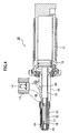
- Fig. 14 is a diagram representing the condition of completed preparation for welding, with a stud held at the tip of the welding gun diagrammed in Fig. 4;
- Embodiments of the present invention are now described with reference to the drawings. Fig. 4 diagrams the
welding gun 10 of a stud welding apparatus. The stud welding apparatus has, besides thewelding gun 10, a conventional electric power supply and a conventional controller (neither shown in the drawings). Thewelding gun 10 comprises anair cylinder 11 that forms the aft portion of the gun, areceiver 15, linked to afeed tube 13 and forming the central part of the welding gun, for receivingstuds 14 that are sent under pressure by compressed air through thefeed tube 13, a tubularfirst collet member 17 that forms the tip part of thewelding gun 10, and atubular collet cover 18. Apiston 19 is deployed in theair cylinder 11. Thepiston 19 is moved to the tip end of thewelding gun 10 by the supply of compressed air to theair cylinder 11 on the back side of the piston, and is returned to its original position by the supply of compressed air to theair cylinder 11 on the front side of the piston as air is exhausted at the back side of the piston. To thepiston 19 is linked apiston rod 21 which passes through thereceiver 15 and extends to thefirst collet member 17. A tubularsecond collet member 22 is secured to the tip of thepiston rod 21. The tubularsecond collet member 22 is made capable of insertion into thefirst collet member 17, and thefirst collet member 17 andsecond collet member 22 form the collet of thewelding gun 10. More specifically, as diagrammed in Fig. 4, thesecond collet member 22 holds the shank of astud 14 when in the state of being inserted into thefirst collet member 17, and thefirst collet member 17 holds thesecond collet member 22 that is holding thefirst collet member 17 when in the state of being extended out from the tip of the flange, constituting a collet that holds thestud 14, with its flange to the fore, at the tip of thewelding gun 10. - The details of the
receiver 15 are diagrammed in Fig. 5 and Fig. 6. Thereceiver 15 is formed in a tubular shape of an electrically conductive material. Theaft part 23 of thereceiver 15 is linked to theair cylinder 11, while to thetip part 25 thereof is linked thefirst collet member 17. In the middle part thereof, astud receptacle 26 linked to thefeed tube 13 is opened, for receivingstuds 14 sent under pressure from thefeed tube 13. Inside thereceiver 15, astud feed path 27 is formed for guiding studs from thefeed tube 13 to thefirst collet member 17. In thestud feed path 27 is formed apiston hole 29 so that thepiston rod 21 andsecond collet member 22 can advance inside thefirst collet member 17. In thestud feed path 27 is deployed an opening and closinggate 30 which closes so as to prevent a stud from tumbling at the exit of thepiston hole 29 and opens so as not to impede the advance of thepiston rod 21 and thesecond collet member 22. The opening and closinggate 30 is supported so that it can turn by apin 31, and a movingspace 33 is formed on the aft side of the opening and closing gate so as not to impede the turning motion of the opening and closinggate 30. The opening and closinggate 30 sends studs that are sent under pressure to thestud receptacle 26, with their flanges to the fore, to thetip part 25, as they are, but does not interfere with thesecond collet member 22, which picks up the shanks of studs sent from thetip part 25 to thefirst collet member 17, from passing from theaft part 23 through thepiston hole 29 to be inserted into thefirst collet member 17. - The
air cylinder 11,piston 19,piston rod 21, andsecond collet member 22 are now described with reference to Fig. 4 and Fig. 7. Theair cylinder 11 forms the aft part of thewelding gun 10, accommodates thepiston 19 inside so that it is movable, and is supplied with compressed air on the back side of the piston (right side in Fig. 4). By the supply of compressed air, thepiston 19 is moved to the tip end (left side) as indicated in Fig. 4. The configuration is made such that, in order to return thepiston 19 to its original position, the compressed air at the back side of the piston is exhausted, and compressed air is supplied to the front side of thepiston 19. Instead of the configuration described above, it is also permissible to make provision so that the compressed air is exhausted from the back side of the piston and vacuum suction is additionally applied. As detailed in Fig. 7, thepiston rod 21 is linked to thepiston 19, to the tip whereof thepiston rod 21 is linked, and thepiston 19,piston rod 21, andsecond collet member 22 are integrally linked to thepiston 19. Thepiston 19 andpiston rod 21 are formed of an electrically nonconductive material, but thesecond collet member 22 is formed of an electrically conductive material. Thesecond collet member 22 is secured to the tip of thepiston rod 21 by screw fastening, for example. To the tip of thesecond collet member 22, a plurality of dividedchannels 34 which extend in the axial dimension is formed so as to elastically hold the shank of thestud 14, and ataper 35 is formed to make it easy to pick up the end of thestud 14. The inner diameter of thesecond collet member 22 is formed so as to be either substantially the same as or slightly smaller than the outer diameter of the stud shank so as to accommodate and elastically hold the stud shank. The outer diameter of thesecond collet member 22 is formed smaller than the diameter of the stud flange so that the flange cannot fit inside it, and is formed slightly smaller than the inner diameter of the first collet member so that, while insertion into thefirst collet member 17 is possible, no more gap is created between the inner wall surface than is absolutely unavoidable. At the center axis of thesecond collet member 22, astop pin 37 for limiting the depth of the second collet member extends from thepiston rod 21, and provision is made so that a stud received into thesecond collet member 22 has the shank thereof received such that the flange thereof is protruding, so that the shank will not overly advance any farther. - The
first collet member 17 is now described with reference to Fig. 4 and Fig. 8. Thefirst collet member 17 is formed as a tubular body of electrically conductive material, theaft part 38 thereof is secured together with the aft part of thecollet cover 18 to thetip part 25 of thereceiver 15, and the tip part of thetubular welding gun 10 is thus configured. At the tip of thefirst collet member 17, a plurality of dividingchannels 39 which extend in the axial dimension is formed, exhibiting elasticity to open to the outside in the radial dimension. At the tip of thefirst collet member 17, moreover, atapered part 41 is formed, made so that it that becomes smaller in diameter toward the tip so as to be smaller than the outer diameter of the stud flange. Dividingchannels 39 are formed in this tapered part also, opening elastically to a larger diameter than the stud flange so that the flange can pass, but contracting in diameter elastically to the original diameter after stud flange passage to block retreat of the flange. The angle α of thetapered part 41 need only be a small angle such that flange passage is allowed but retreat is blocked. Thesecond collet member 22 is inserted inside thefirst collet member 17. The inner diameter of thefirst collet member 17 is formed to such size that it will accept the stud flange and accept the second collet member so that it is movable with the gap kept small. Thefirst collet member 17, except for thetapered part 41 and theaft part 38, is formed of thin material so as to have the elasticity to open outwardly in the radial dimension. - The
collet cover 18 is now detailed with reference to Fig. 4, Fig. 9, and Fig. 10. Thecollet cover 18 is formed of electrically conductive material, being formed in a shape which will enclose the entirety of the exterior of thefirst collet member 17, from the tip end thereof to the portion at the aft end thereof. Theaft part 42 of thecollet cover 18 is formed in a ring shape of larger diameter than the other parts, accepts theaft part 38 of thefirst collet member 17, and also accepts thetip part 25 of thereceiver 15, withfemale threads 45 formed so as to be engaged securely bymale threads 43 in thetip part 25. The main part from theaft part 42 to thetip part 46 is formed as a tubular body, and accommodates thefirst collet member 17 inside. Thetip part 46 is formed with a small diameter so as to temporarily stop studs which are sent thereto under pressure, and atapered part 47 is formed which becomes smaller in diameter toward the tip to make it possible to push the stud flanges to the outside of the tip. In addition, dividingchannels 49 which extend in the axial dimension from thetip part 46 to the back side are formed, which open to a larger diameter than the stud flange when a stud temporarily stopped at thetip part 46 is pushed and moved so as to allow the flange to pass, and elasticity for diameter contraction after that passage is imparted to thetip part 46. - On the inside of the
tip part 46 of thecollet cover 18, a ring-shapedconcavity 50 is formed. This works together with thetapered part 41 at the tip of thefirst collet member 17 to form a space for accommodating and holding the edge of the stud flange. Fig. 10 shows how, with thefirst collet member 17 assembled so as to be enclosed in thecollet cover 18, astud 14 is sent to the position in thefirst collet member 17 indicated by the solid lines, and then is sent to the position indicated by the broken lines. As indicated in Fig. 10, the ring-shapedconcavity 50 on the inside of thetip part 46 of thecollet cover 18 forms a flangeedge carrying space 54, the aft end portion whereof is determined by the tip surface of thetapered part 41 at the tip of thefirst collet member 17, which accommodates and holds theflange 51 of thestud 14 and holds the end of thestud shank 53 in such attitude that it floats free from the inner wall of thefirst collet member 17. The flangeedge carrying space 54 may be formed in any shape whatever so long as it holds the edge of astud 14 that has passed through thetapered part 41 of thefirst collet member 17 and stopped at thetip part 46 of the collet cover, and holds the tip of thestud shank 53 in an attitude such that it floats free from the inner wall of thefirst collet member 17. Because the tip of thestud shank 53 is in an attitude of floating free from the inner wall of thefirst collet member 17, in this manner, it is extremely easy to accommodate thestud shank 53 in thesecond collet member 22, and the necessity of forming a taper in the end of thestud shank 53 is eliminated. Thetaper 35 in the tip of thesecond collet member 22 also becomes almost entirely unnecessary, and the length of thetaper 35 can be shortened. - A
flanged stud 14 that can be used with the stud welding apparatus to which the present invention pertains is detailed in Fig. 11. Thestud 14 has aflange 51 of large diameter and ashank 53 wherein are formed screw threads or (a) circumferential groove(s), for example. Thestud 14, unlike thestud 2 diagrammed in Fig. 2, has no tapered part formed at the tip of theshank 53. Let thisstud 14 here have an overall length of L1, aflange 51 diameter of D1, and ashank 53 outer diameter of d1. When these are the dimensions, the inner diameter D2 of thetapered part 41 of the first collet member 17 (cf. Fig. 8) is made slightly smaller than the flange diameter D1, and blocks retreat of the flange after passage. Also, the diameter D3 of thetip part 46 of the collet cover 18 (cf. Fig. 9) is made smaller than the inner diameter D2 of thetapered part 41 and smaller than the flange diameter D1 so as to insure the temporary stoppage of the flange, and blocks retreat of the flange after the flange passes, but is selected so as to make passage of the flange possible. The outer diameter D4 of the second collet member 22 (see Fig. 7), moreover, is made smaller than the flange diameter D1. The inner diameter d2 of the second collet member (see Fig. 7) is made either substantially the same as or slightly smaller than the stud shank outer diameter d1 so that thesecond collet member 22 accepts and mechanically holds thestud shank 53 and also effects electrical contact. The inner diameter of thefirst collet member 17, furthermore, is formed to an inner diameter that accepts studs sent thereto, flange to the fore, and accepts thesecond collet member 22 so that it is movable, while the inner diameter of thecollet cover 18 is formed so as to accept thefirst collet member 17 and so as to have a space in the tip part thereof that will enable opening toward the outside when thetapered part 41 at the tip of thefirst collet member 17 passes thestud flange 51. - The operation of the
welding gun 10 of the stud welding apparatus configured as described above is now described with reference to Fig. 12 to Fig. 14. In Fig. 12, astud 14 is supplied from a parts feeder (not shown) through thefeed tube 13 to thereceiver 15. When this happens, thepiston rod 21 which has thesecond collet member 22 at its tip (and the piston 19) will be retracted to the start position inside theair cylinder 11, and will have opened thestud feed path 27 inside thereceiver 15. The opening and closinggate 30 is pushed against the wall surface of thereceiver 15 by the compressed air which sends thestud 14 under pressure, so thepiston hole 29 will be closed off, and thestud 14 will pass through thestud feed path 27 inside thereceiver 15. Reference is now made to Fig. 10 which shows how thestud 14 which has passed through thestud feed path 27 is sent to thefirst collet member 17. Thestud 14 which has passed through thereceiver 15 is sent under pressure toward thetapered part 41 at the tip, inside thefirst collet member 17 by compressed air. Theflange 51 of thestud 14, due to the pressure of the compressed air, pushes open thetapered part 41, arrives at thetapered part 47 of thetip part 46 of thecollet cover 18, and stops. As described earlier, the flangeedge carrying space 54 is formed between thetip part 46 of thecollet cover 18 and thetapered part 41 of thefirst collet member 17. Thisspace 54 holds astud flange 51 that has entered thisspace 54 by its edge, and holds the end of thestud flange 51 in an attitude such that it floats free from the inner wall of thefirst collet member 17. At this time, even if thestud 14 tends to change its attitude, the edge of theflange 51 is limited inside the flangeedge carrying space 54, wherefore the end of thestud shank 53 is limited to a free-floating attitude relative to the inner wall surface of thefirst collet member 17. - Next, as diagrammed in Fig. 13, compressed air is supplied to the
air cylinder 11 from the back side of thepiston 19, thepiston 19 and thepiston rod 21 advance, and thesecond collet member 22 at the tip of thepiston rod 21 turns the opening and closinggate 30 from thepiston hole 29 of thereceiver 15, passes through thereceiver 15, and is inserted into thefirst collet member 17. Thesecond collet member 22 which advances inside thefirst collet member 17 picks up the end of theshank 53 of thestud 14 by thetaper 35 part at the tip thereof and accommodates theshank 53 in the interior thereof. The end of thestud shank 53 is secured in an attitude such that it floats free from the inner wall surface of thefirst collet member 17, wherefore, even if there is almost notaper 35 part at the tip of thesecond collet member 22, the end of the shank 35 [sic] can be picked up and accommodated inside thesecond collet member 22. Thestud shank 53 so accommodated is mechanically held in thesecond collet member 22 and makes electrical contact. - When compressed air is further supplied to the
air cylinder 11, thepiston 19 and thepiston rod 21 move in the direction of the tip, as diagrammed in Fig. 14, and thesecond collet member 22 that accommodates and holds theshank 53 of thestud 14 moves inside thefirst collet member 17 to the tip end with theflange 51 that is in the flangeedge carrying space 54 to the fore. In thesecond collet member 22, because thestop pin 37 extends from thepiston rod 21, thestud shank 53 will not be admitted inside thesecond collet member 22 more than a certain length, but will be held with theflange 51 protruding a prescribed length. Meanwhile, thepiston 19 moves as is to the stroke end, wherefore thesecond collet member 22 at the tip of thepiston rod 21 will push theflange 51, of thestud 14 being held, so that it pushes apart the wall of thetip part 46 of thecollet cover 18. Thestud 14, as a consequence thereof, is held mechanically and securely, and inserted into thefirst collet member 17 inside thecollet cover 18 with theshank 53 electrically connected to thesecond collet member 22, in such condition that theflange 51 protrudes a certain length from thetip part 46 of thecollet cover 18. In this manner, thestuds 14 are automatically loaded in an appropriate attitude at the tip of thewelding gun 10. In this condition, the electricallyconductive collet cover 18, the electrically conductivefirst collet member 17, the electrically conductivesecond collet member 22, and the electricallyconductive receiver 15 make electrical contact. Therefore, if a welding current is supplied either directly to thereceiver 15 or through theair cylinder 11 to thereceiver 15, welding to thestud 14 will become possible. - After the welding of the
stud 14 is finished, the compressed air at the back side of thepiston 19 in theair cylinder 11 is exhausted, and compressed air is supplied to the front side of thepiston 19. Thereby, thepiston 19 is returned to its original position, and thesecond collet member 22 at the tip of thepiston rod 21 is also returned to the position indicated in Fig. 12. Provision may also be made so as to apply vacuum suction also while exhausting the compressed air from the air cylinder chamber on the back side of the piston, and thereby cause thepiston 19, thepiston rod 21, and thesecond collet member 22 to return. - As described in the foregoing, the
stud 14 is held so that the end of theshank 53 is in an attitude wherein it is floating free from the inner wall of thefirst collet member 17. Therefore, thestud shank 53 is readily accommodated in thesecond collet member 22, no tapered part whatever is necessary at the tip of the stud shank, the length L2 of the tapered part at the tip of the shank diagrammed in Fig. 2 and Fig. 3 can be done away with, and the length b of thetapered part 8 of the second collet member diagrammed in Fig. 2 and Fig. 3 can be considerably shortened. The overall length L1 of thestud 14 diagrammed in Fig. 11 can be shortened to a length of from 1.0 × D1 to 1.2 × D1 (where D1 is the diameter of the flange 51). - While a preferred embodiment of the invention has been shown and described, it will be apparent that changes can be made without departing from the principles of the invention, the scope of which is defined in the following claims.
Claims (6)
- A stud welding apparatus having a collet for holding a stud with a flange and a shank at the tip of a welding gun (10), said collet comprising:a tubular first collet member (17) secured to the tip of said welding gun, for elastically opening to a larger diameter than said flange to hold said flange at the tip; and a tubular second collet member (22) secured to the tip of a piston rod (21) that extends toward said first collet member from a cylinder (11) provided in the aft portion of said welding gun, capable of insertion into said first collet member, for, by the movement of said piston rod, picking up, accommodating, and holding the shank of a stud fed with the flange to the fore into the interior of said first collet member, wherein:a collet cover (18) is provided for enclosing the exterior of said first collet member (17) from the tip of the welding gun; and a tip of said collet cover and a tip of said first collet member form a flange edge carrying space (54) for accommodating and holding an edge of the stud flange and holding the stud shank in an attitude such that it floats free of an inner wall of said first collet member.
- The apparatus according to claim 1, wherein axial dividing channels (49) are formed in the tip of said collet cover (18), exhibiting elasticity such that, when a flange that is in said flange edge carrying space is pushed and moved, the tip of said collet cover expands to a larger diameter than said flange, to allow the passage of said flange, and contracts in diameter after that passage to hold the stud shank together with said first collet member.
- The apparatus according to anyone of Claims 1 and 2, wherein said second collet member (22) is such that the depth of a cylindrical member that accepts the stud shank is limited by a stop pin (37) that extends from said piston rod (21).
- The apparatus according to anyone of the preceding Claims, wherein said collet cover (18), said first collet member (17), and said second collet member (22) are formed of an electrically conductive material.
- The apparatus according to anyone of the preceding Claims, wherein a receiver (15) to which is linked a feed tube (13) for feeding studs is deployed between said first collet member (17) and said cylinder (11), said receiver has formed therein a stud feed path (27) for guiding studs (14) from the feed tube to the first collet member, a piston hole (29) is formed in said stud feed path such that said piston rod (21) of said cylinder and said second collet member (22) can advance into the interior of said first collet member.
- The apparatus according to anyone of the preceding Claims, wherein an opening and closing gate (30) is deployed in said stud feed path (27), which closes so as to prevent studs from tumbling in said piston hole and opens so as not to impede the movement of said piston and second collet member.
Applications Claiming Priority (2)
| Application Number | Priority Date | Filing Date | Title |
|---|---|---|---|
| JP2003194363 | 2003-07-09 | ||
| JP2003194363A JP4011524B2 (en) | 2003-07-09 | 2003-07-09 | Stud welding equipment |
Publications (2)
| Publication Number | Publication Date |
|---|---|
| EP1495828A1 EP1495828A1 (en) | 2005-01-12 |
| EP1495828B1 true EP1495828B1 (en) | 2006-05-24 |
Family
ID=33447998
Family Applications (1)
| Application Number | Title | Priority Date | Filing Date |
|---|---|---|---|
| EP04015570A Active EP1495828B1 (en) | 2003-07-09 | 2004-07-02 | Stud welding apparatus |
Country Status (4)
| Country | Link |
|---|---|
| US (1) | US7071440B2 (en) |
| EP (1) | EP1495828B1 (en) |
| JP (1) | JP4011524B2 (en) |
| DE (1) | DE602004000960T2 (en) |
Cited By (3)
| Publication number | Priority date | Publication date | Assignee | Title |
|---|---|---|---|---|
| DE102008033371A1 (en) | 2008-07-08 | 2010-01-14 | Newfrey Llc, Newark | Bolt retainer |
| EP2246140A1 (en) | 2009-04-29 | 2010-11-03 | Newfrey LLC | Joining head arrangement and joining method |
| EP2258508A1 (en) | 2009-06-02 | 2010-12-08 | Newfrey LLC | Head arrangement for joining component with a hinged component holder ; Method of feeding a component to a hinged component holder |
Families Citing this family (12)
| Publication number | Priority date | Publication date | Assignee | Title |
|---|---|---|---|---|
| DE102004042970A1 (en) * | 2004-09-02 | 2006-03-09 | Heiko Schmidt | System for inserting nuts into workpieces and loading device for such a system |
| DE102006016553B4 (en) * | 2006-04-07 | 2008-02-14 | Heinz Soyer Bolzenschweisstechnik Gmbh | Method and system for arc stud welding and welding studs |
| DE102009023454A1 (en) * | 2009-06-02 | 2010-12-09 | Newfrey Llc, Newark | Stud holding device for bolts with large flanged heads |
| FR2975618B1 (en) * | 2011-05-27 | 2013-05-31 | Peugeot Citroen Automobiles Sa | ELECTRIC WELDING DEVICE HAVING A REINFORCED LAMINATED WELDING PLIERS |
| JP5851868B2 (en) | 2012-02-03 | 2016-02-03 | 三菱重工業株式会社 | Bar-shaped member chucking device and bar-shaped member chucking method |
| DE102016112372A1 (en) * | 2016-07-06 | 2018-01-11 | Newfrey Llc | Joining device and method for loading a joining element |
| CA3072829C (en) | 2017-12-14 | 2023-10-10 | Arconic Inc. | Collet assembly for fastener feeding apparatus |
| EP3527318B1 (en) * | 2018-02-16 | 2023-05-17 | Newfrey LLC | Holding device for holding a stud and joining head |
| JP6940687B2 (en) * | 2018-03-29 | 2021-09-29 | 本田技研工業株式会社 | Welding gun and welding method |
| JP7407015B2 (en) | 2020-02-19 | 2023-12-28 | ポップリベット・ファスナー株式会社 | Self-drilling rivet fastening device |
| CN112809139B (en) * | 2021-02-03 | 2023-12-29 | 浙江上势自动焊接科技有限公司 | Telescopic automatic stud welding gun |
| CN116571926B (en) * | 2023-06-28 | 2024-01-26 | 广东鸿栢科技有限公司 | Short nail feeding device |
Family Cites Families (13)
| Publication number | Priority date | Publication date | Assignee | Title |
|---|---|---|---|---|
| US3758743A (en) * | 1970-06-30 | 1973-09-11 | Omark Industries Inc | Chuck assembly for stud welding apparatus |
| US3723700A (en) * | 1972-02-28 | 1973-03-27 | Fastener Corp | Welding gun means for feeding and holding head-bearing studs or the like |
| DE3408930C1 (en) * | 1984-03-12 | 1985-06-27 | OBO Bettermann oHG, 5750 Menden | Stud welding device |
| JPS62155963A (en) | 1985-12-27 | 1987-07-10 | Fujitsu Ltd | Selective coating device |
| JPS62202977A (en) | 1986-02-28 | 1987-09-07 | 富士電機株式会社 | Controller for refrigerant feeder |
| JPS62202977U (en) * | 1986-06-16 | 1987-12-24 | ||
| JPS63196368A (en) | 1987-02-09 | 1988-08-15 | Yasushi Kato | Polishing method using magnetic fluid |
| JP2569537Y2 (en) * | 1992-08-24 | 1998-04-28 | ポップリベット・ファスナー株式会社 | Stud welding gun |
| DE4322831C1 (en) * | 1993-07-08 | 1994-06-30 | Bettermann Obo Ohg | Device for contact welding of welding studs |
| JP3376159B2 (en) * | 1995-04-13 | 2003-02-10 | ポップリベット・ファスナー株式会社 | Stud welding equipment |
| US5798494A (en) * | 1996-06-24 | 1998-08-25 | Aoyama; Yoshitaka | Welding apparatus |
| DE29617208U1 (en) * | 1996-10-02 | 1996-12-05 | Emhart Inc | Stud holder for a stud welding device |
| JP3716116B2 (en) * | 1998-12-22 | 2005-11-16 | 関東自動車工業株式会社 | Stud welding equipment |
-
2003
- 2003-07-09 JP JP2003194363A patent/JP4011524B2/en not_active Expired - Fee Related
-
2004
- 2004-07-02 DE DE602004000960T patent/DE602004000960T2/en not_active Expired - Fee Related
- 2004-07-02 EP EP04015570A patent/EP1495828B1/en active Active
- 2004-07-06 US US10/883,808 patent/US7071440B2/en not_active Expired - Fee Related
Cited By (6)
| Publication number | Priority date | Publication date | Assignee | Title |
|---|---|---|---|---|
| DE102008033371A1 (en) | 2008-07-08 | 2010-01-14 | Newfrey Llc, Newark | Bolt retainer |
| EP2246140A1 (en) | 2009-04-29 | 2010-11-03 | Newfrey LLC | Joining head arrangement and joining method |
| DE102009019130A1 (en) | 2009-04-29 | 2010-11-04 | Newfrey Llc, Newark | Joining head arrangement and joining method |
| US8344280B2 (en) | 2009-04-29 | 2013-01-01 | Newfrey Llc | Front loading stud welding head |
| EP2258508A1 (en) | 2009-06-02 | 2010-12-08 | Newfrey LLC | Head arrangement for joining component with a hinged component holder ; Method of feeding a component to a hinged component holder |
| DE102009023453A1 (en) | 2009-06-02 | 2010-12-09 | Newfrey Llc, Newark | Joining head arrangement and joining method |
Also Published As
| Publication number | Publication date |
|---|---|
| JP4011524B2 (en) | 2007-11-21 |
| JP2005028390A (en) | 2005-02-03 |
| DE602004000960T2 (en) | 2007-01-04 |
| US7071440B2 (en) | 2006-07-04 |
| EP1495828A1 (en) | 2005-01-12 |
| DE602004000960D1 (en) | 2006-06-29 |
| US20050023252A1 (en) | 2005-02-03 |
Similar Documents
| Publication | Publication Date | Title |
|---|---|---|
| EP1495828B1 (en) | Stud welding apparatus | |
| KR100380129B1 (en) | Riveting device | |
| EP0084419B1 (en) | Resectoscopes | |
| US7109434B2 (en) | Device and method for short cycle arc welding | |
| JPH02109280A (en) | High voltage load breaking type bush insert | |
| US4620079A (en) | Stud welding device | |
| US20210057839A1 (en) | Adaptive multi-purpose pneumatic electric connector | |
| US20170064804A1 (en) | Plasma torch and components thereof | |
| US3723700A (en) | Welding gun means for feeding and holding head-bearing studs or the like | |
| ES2953599T3 (en) | Resistance spot rivet welding system and methods of using them | |
| EP2376254B1 (en) | Stud welding apparatus | |
| US20170361391A1 (en) | Loading pin for a joining device, joining device and joining element feed method | |
| EP1033797B1 (en) | Pulse power system | |
| CN108011208B (en) | Electrification connects J-type wire clamp operating stick tool and connects the livewire work method of branch's lead | |
| JP5871831B2 (en) | ENVIRONMENT FORMING APPARATUS AND GOODS / OUT METHODS FOR ENVIRONMENT FORMING APPARATUS | |
| JP2022120002A (en) | Nut supply device | |
| CN107645976A (en) | Length-adjustable robot cable accessory | |
| EP0178117B1 (en) | Stud welding device | |
| EP0332905B1 (en) | Welding electrode holding device with quick ejection of the worn out electrode | |
| KR102061113B1 (en) | Stud welding gun | |
| JP2007288966A (en) | Rubber-plug insertion device | |
| US3138423A (en) | Upper end airplane antenna mast | |
| JP7108252B2 (en) | Supply rod for cap nuts and supply method | |
| US10781937B2 (en) | Actuator assembly and method of securing an actuator to a valve body | |
| CN114632998A (en) | Robot flying arc striking device and method in welding process |
Legal Events
| Date | Code | Title | Description |
|---|---|---|---|
| PUAI | Public reference made under article 153(3) epc to a published international application that has entered the european phase |
Free format text: ORIGINAL CODE: 0009012 |
|
| AK | Designated contracting states |
Kind code of ref document: A1 Designated state(s): AT BE BG CH CY CZ DE DK EE ES FI FR GB GR HU IE IT LI LU MC NL PL PT RO SE SI SK TR |
|
| AX | Request for extension of the european patent |
Extension state: AL HR LT LV MK |
|
| 17P | Request for examination filed |
Effective date: 20050701 |
|
| AKX | Designation fees paid |
Designated state(s): DE ES FR GB IT |
|
| GRAP | Despatch of communication of intention to grant a patent |
Free format text: ORIGINAL CODE: EPIDOSNIGR1 |
|
| GRAS | Grant fee paid |
Free format text: ORIGINAL CODE: EPIDOSNIGR3 |
|
| GRAA | (expected) grant |
Free format text: ORIGINAL CODE: 0009210 |
|
| AK | Designated contracting states |
Kind code of ref document: B1 Designated state(s): DE ES FR GB IT |
|
| PG25 | Lapsed in a contracting state [announced via postgrant information from national office to epo] |
Ref country code: IT Free format text: LAPSE BECAUSE OF FAILURE TO SUBMIT A TRANSLATION OF THE DESCRIPTION OR TO PAY THE FEE WITHIN THE PRESCRIBED TIME-LIMIT;WARNING: LAPSES OF ITALIAN PATENTS WITH EFFECTIVE DATE BEFORE 2007 MAY HAVE OCCURRED AT ANY TIME BEFORE 2007. THE CORRECT EFFECTIVE DATE MAY BE DIFFERENT FROM THE ONE RECORDED. Effective date: 20060524 |
|
| REG | Reference to a national code |
Ref country code: GB Ref legal event code: FG4D |
|
| REF | Corresponds to: |
Ref document number: 602004000960 Country of ref document: DE Date of ref document: 20060629 Kind code of ref document: P |
|
| PG25 | Lapsed in a contracting state [announced via postgrant information from national office to epo] |
Ref country code: ES Free format text: LAPSE BECAUSE OF FAILURE TO SUBMIT A TRANSLATION OF THE DESCRIPTION OR TO PAY THE FEE WITHIN THE PRESCRIBED TIME-LIMIT Effective date: 20060904 |
|
| PLBE | No opposition filed within time limit |
Free format text: ORIGINAL CODE: 0009261 |
|
| STAA | Information on the status of an ep patent application or granted ep patent |
Free format text: STATUS: NO OPPOSITION FILED WITHIN TIME LIMIT |
|
| 26N | No opposition filed |
Effective date: 20070227 |
|
| EN | Fr: translation not filed | ||
| PG25 | Lapsed in a contracting state [announced via postgrant information from national office to epo] |
Ref country code: FR Free format text: LAPSE BECAUSE OF FAILURE TO SUBMIT A TRANSLATION OF THE DESCRIPTION OR TO PAY THE FEE WITHIN THE PRESCRIBED TIME-LIMIT Effective date: 20070309 |
|
| PGFP | Annual fee paid to national office [announced via postgrant information from national office to epo] |
Ref country code: DE Payment date: 20080829 Year of fee payment: 5 |
|
| PG25 | Lapsed in a contracting state [announced via postgrant information from national office to epo] |
Ref country code: FR Free format text: LAPSE BECAUSE OF FAILURE TO SUBMIT A TRANSLATION OF THE DESCRIPTION OR TO PAY THE FEE WITHIN THE PRESCRIBED TIME-LIMIT Effective date: 20060524 |
|
| GBPC | Gb: european patent ceased through non-payment of renewal fee |
Effective date: 20080702 |
|
| PG25 | Lapsed in a contracting state [announced via postgrant information from national office to epo] |
Ref country code: GB Free format text: LAPSE BECAUSE OF NON-PAYMENT OF DUE FEES Effective date: 20080702 |
|
| PG25 | Lapsed in a contracting state [announced via postgrant information from national office to epo] |
Ref country code: DE Free format text: LAPSE BECAUSE OF NON-PAYMENT OF DUE FEES Effective date: 20100202 |