EP1494591B1 - Side loading surgical retractor - Google Patents
Side loading surgical retractor Download PDFInfo
- Publication number
- EP1494591B1 EP1494591B1 EP03736452A EP03736452A EP1494591B1 EP 1494591 B1 EP1494591 B1 EP 1494591B1 EP 03736452 A EP03736452 A EP 03736452A EP 03736452 A EP03736452 A EP 03736452A EP 1494591 B1 EP1494591 B1 EP 1494591B1
- Authority
- EP
- European Patent Office
- Prior art keywords
- slide
- surgical retractor
- socket
- connector head
- socket cavity
- Prior art date
- Legal status (The legal status is an assumption and is not a legal conclusion. Google has not performed a legal analysis and makes no representation as to the accuracy of the status listed.)
- Expired - Lifetime
Links
- 230000033001 locomotion Effects 0.000 description 4
- 238000010276 construction Methods 0.000 description 2
- 230000003466 anti-cipated effect Effects 0.000 description 1
- 230000000694 effects Effects 0.000 description 1
- 210000003811 finger Anatomy 0.000 description 1
- 230000001788 irregular Effects 0.000 description 1
- 238000003754 machining Methods 0.000 description 1
- 238000000034 method Methods 0.000 description 1
- 238000001356 surgical procedure Methods 0.000 description 1
- 210000003813 thumb Anatomy 0.000 description 1
Images
Classifications
-
- A—HUMAN NECESSITIES
- A61—MEDICAL OR VETERINARY SCIENCE; HYGIENE
- A61B—DIAGNOSIS; SURGERY; IDENTIFICATION
- A61B17/00—Surgical instruments, devices or methods
- A61B17/02—Surgical instruments, devices or methods for holding wounds open, e.g. retractors; Tractors
- A61B17/0206—Surgical instruments, devices or methods for holding wounds open, e.g. retractors; Tractors with antagonistic arms as supports for retractor elements
-
- A—HUMAN NECESSITIES
- A61—MEDICAL OR VETERINARY SCIENCE; HYGIENE
- A61B—DIAGNOSIS; SURGERY; IDENTIFICATION
- A61B1/00—Instruments for performing medical examinations of the interior of cavities or tubes of the body by visual or photographical inspection, e.g. endoscopes; Illuminating arrangements therefor
- A61B1/32—Devices for opening or enlarging the visual field, e.g. of a tube of the body
-
- A—HUMAN NECESSITIES
- A61—MEDICAL OR VETERINARY SCIENCE; HYGIENE
- A61B—DIAGNOSIS; SURGERY; IDENTIFICATION
- A61B17/00—Surgical instruments, devices or methods
- A61B17/28—Surgical forceps
- A61B17/2812—Surgical forceps with a single pivotal connection
-
- A—HUMAN NECESSITIES
- A61—MEDICAL OR VETERINARY SCIENCE; HYGIENE
- A61B—DIAGNOSIS; SURGERY; IDENTIFICATION
- A61B17/00—Surgical instruments, devices or methods
- A61B2017/0046—Surgical instruments, devices or methods with a releasable handle; with handle and operating part separable
- A61B2017/00464—Surgical instruments, devices or methods with a releasable handle; with handle and operating part separable for use with different instruments
-
- A—HUMAN NECESSITIES
- A61—MEDICAL OR VETERINARY SCIENCE; HYGIENE
- A61B—DIAGNOSIS; SURGERY; IDENTIFICATION
- A61B17/00—Surgical instruments, devices or methods
- A61B17/28—Surgical forceps
- A61B17/2812—Surgical forceps with a single pivotal connection
- A61B17/2833—Locking means
- A61B2017/2837—Locking means with a locking ratchet
Definitions
- the present invention relates generally to a surgical retractor apparatus used with interchangeable retractor blades. More particular the present invention relates to a surgical retractor with side loading interchangeable retractor blades.
- U.S. Patent No. 6,042,540 allows for the top loading as well as the side loading of retractor blades into a socket.
- the side loading feature of this, and other prior art is believed to be advantageous whereby the surgeon's vision is not obscured while connecting, or disconnecting a blade from a retractor.
- the '540 Patent discloses a number of retractors which can utilize the blade of Figure 1A, specifically, the longitudinal retractor of Figure 3 , the transverse retractor of Figure 4 , and the side-loading hand-held retractor of Figure 5 .
- the '540 Patent utilizes a "cam member” to restrain a connector head within a socket cavity.
- cams are known in the art typically as: "a disc or cylinder having an irregular form such that its motion, usually rotary gives to a part or parts in contact with it a specific rocking or reciprocating motion or motions".
- the rotation of the cam 130 about pivot 128 locks and unlocks the connector head from within the socket chamber.
- the release lever 124 rotates and extends away from the socket 12 as the cam is moved in and out of the socket chamber.
- cam is described as being positioned at least partially "within" a side loading socket. While this design appears to allow for the grip of the socket to tighten if a blade were to be attempted to be pulled side-ways out of the socket cavity, this tightening effect also would appear to cause an inserted connector head to bind instead of rotate within the socket cavity.
- a surgical retractor includes a body having a socket for receiving a connector head.
- the socket has a slide which moves linearly toward and away from a connector head when positioned within the socket.
- a convex surface on a first face of the slide allows for the connector head to be pushed into position or "snapped" in, while a convex surface on a second face of the slide is believed to assist in retaining an inserted connector head in position within the socket
- the second face of the socket may also be constructed with a notch at a tip of the slide which allows pinned hubs to be received within the notch to resist turning in at least one direction. While the preferred embodiments accepts only side loaded connector heads, other non-preferred embodiments could accept top loaded connector heads as well.
- the invention relates to a surgical retractor according to claim 1.
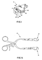
- FIG 1 illustrates a preferred embodiment of a surgical retractor 10 having at least one, and preferably two, sockets 12 as shown in Figures 2-5 .
- Other retractor designs may also utilize the socket 12 of the present invention.
- the socket 12 of this design receives a connector head 14 in a side loading manner.
- at least one protuberance such as one or more pins or ledge 16
- top loading maybe allowed, such as if the ledge 16 is not provided, does not sufficiently extend within the socket chamber 18, or otherwise.
- the connector head shown and described in co-pending and co-owned Patent Application No. 60/327,437 works well with the socket 12 of the preferred embodiment.
- the ledge 16 is preferably located internal in top 11 and bottom 13 of socket cavity.
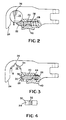
- the preferred embodiment utilizes a linearly moving slide 20.
- the slide 20 is moveable in a linear manner between a locked position as shown in Figure 3 , and an unlocked position shown in phantom in Figure 4.
- Figure 4 also shows an intermediate position, such as might occur if a connector head 14 were "snapped" into position within the socket chamber 18 as will be described in further detail below.
- the slide 20 has a first face 22 which is directed outward from the socket cavity 18.
- the first face 22 is preferably convex so that when a connector head, which is traditionally cylindrical in shape, is pushed against the first face 22 and director 24 toward the socket cavity 18 , the slide 20 is deflected into slot 26.
- the slot 26 receives the slide 20 so that the slide 20 or other component does not extend further away from the socket 12 to potentially snag something.
- Spring 28 normally biases the slide 20 into the locked position shown in Figure 2 . Accordingly, when the bias of spring 28 is overcome by a connector head 14 being directed within the socket cavity 18 , the connector head 14 "snaps" into position since once the head clears the tip 30 of the slide 20 , it encounters second face 32 which is concave.
- the concave shape of the second face 32 is believed to be advantageous as it may allow for the circular shape of the socket cavity 18 to be continued so that a circle inscribed along the socket walls 34 would continue along the second face 32. Furthermore the concave shape of the second face 32, in the preferred embodiment, prevents the second face 32 from being positioned in the socket cavity 18.
- the slide 20 has been specifically designed so that it cannot even be partially positioned within the socket 12 , as has been done in the prior art.
- the slide 20 is positioned external to the socket to retain a connector head 14 within the socket cavity 18.
- the slide 20 may assist in defining the socket cavity 18 , especially when the second face 32 of the slide 20 has a similar arc of curvature as the socket wall 34.
- the slide 20 may extend into the socket cavity 18.
- a recess 36 Adjacent to the socket cavity 18 is a recess 36 which may accept a fixing pin of a connector head. Furthermore, at the tip 30 and/or the first face 32 a notch 38 is located which accepts a second fixing pin of a connector head at least partially therein to assist in prevent the locking pin from rotating toward the slide 20. The illustrated notch 38 prevents the connector head 14 from rotating toward the slide 20 when locking pins, if utilized, are oriented toward the recess 36 and notch 38.
- the slide 20 may be operated with the grip 40 which preferably has a textured surface 42 for ease of operation.
- the grip 40 may also be curved to accommodate a user's thumb or finger.
- the grip is connected to the slide 20 by arm 44. Movement of the grip 40 moves the slide 20 accordingly.
- the grip 40 is moveable along the socket 12, not away from the socket 12.
- the slide 20 is linearly moveable within the slot 26.
- a cutout 46 in the director 24 allows for the through machining of the slot 26.
- a suture hole 48 may be provided in the socket body 50.
- a groove 52 along a top portion of the body 50 allows the arm 44 to access the slot 26.
- a similar groove may be located along the bottom portion of the body 50 with another arm.
Landscapes
- Health & Medical Sciences (AREA)
- Life Sciences & Earth Sciences (AREA)
- Surgery (AREA)
- Heart & Thoracic Surgery (AREA)
- Engineering & Computer Science (AREA)
- Biomedical Technology (AREA)
- Nuclear Medicine, Radiotherapy & Molecular Imaging (AREA)
- Medical Informatics (AREA)
- Molecular Biology (AREA)
- Animal Behavior & Ethology (AREA)
- General Health & Medical Sciences (AREA)
- Public Health (AREA)
- Veterinary Medicine (AREA)
- Surgical Instruments (AREA)
Description
- The present invention relates generally to a surgical retractor apparatus used with interchangeable retractor blades. More particular the present invention relates to a surgical retractor with side loading interchangeable retractor blades.
- When conducting some surgical procedures, it is often desirable to retract tissue. Although there are a number of procedures and devices available to retract tissue,
U.S. Patent No. 6,042,540 allows for the top loading as well as the side loading of retractor blades into a socket. The side loading feature of this, and other prior art, is believed to be advantageous whereby the surgeon's vision is not obscured while connecting, or disconnecting a blade from a retractor. The '540 Patent discloses a number of retractors which can utilize the blade of Figure 1A, specifically, the longitudinal retractor ofFigure 3 , the transverse retractor ofFigure 4 , and the side-loading hand-held retractor ofFigure 5 . As shown in Figures 1A and 1C, the blades typically have connector heads locking pins typically extend from opposite sides of the longitudinal axis of the connector head. Although the '540 Patent specifically shows a top loading connector head, other connector heads also employ the opposing locking pin construction.EP 1 192 905 A1 describes a surgical retractor according to the preamble of claim 1. - The '540 Patent utilizes a "cam member" to restrain a connector head within a socket cavity. There are believed to be a number of problems with this design. First, cams are known in the art typically as: "a disc or cylinder having an irregular form such that its motion, usually rotary gives to a part or parts in contact with it a specific rocking or reciprocating motion or motions". In the '540 Patent, the rotation of the cam 130 about pivot 128 locks and unlocks the connector head from within the socket chamber. One of the perceived drawbacks of this "cam" design is the release lever 124 rotates and extends away from the
socket 12 as the cam is moved in and out of the socket chamber. - Another perceived problem with the design shown and described in the '540 Patent is the cam is described as being positioned at least partially "within" a side loading socket. While this design appears to allow for the grip of the socket to tighten if a blade were to be attempted to be pulled side-ways out of the socket cavity, this tightening effect also would appear to cause an inserted connector head to bind instead of rotate within the socket cavity.
- Accordingly, a need exists for an improved retractor design.
- A need exists for a surgical retractor which accepts blades having a connector head at least in a side loading manner.
- Another need exists for a surgical retractor which securely retains connector heads in a socket.
- Another need exists for a side loading surgical retractor socket which does not rely on an awkward cam mechanism.
- Yet another need exists for a side loading surgical retractor socket which allows a connector head to"snap" in to a locked configuration without a need for an operator to manually operate a locking mechanism.
- Accordingly, a surgical retractor includes a body having a socket for receiving a connector head. The socket has a slide which moves linearly toward and away from a connector head when positioned within the socket. A convex surface on a first face of the slide allows for the connector head to be pushed into position or "snapped" in, while a convex surface on a second face of the slide is believed to assist in retaining an inserted connector head in position within the socket The second face of the socket may also be constructed with a notch at a tip of the slide which allows pinned hubs to be received within the notch to resist turning in at least one direction. While the preferred embodiments accepts only side loaded connector heads, other non-preferred embodiments could accept top loaded connector heads as well.
The invention relates to a surgical retractor according to claim 1. - The particular features and advantages of the invention as well as other objects will become apparent from the following description taken in connection with the accompanying drawings in which:
-
Fig. 1 is a top view of a side-loading retractor with the socket ofFigure 2 ; -
Fig. 2 shows a top perspective view of a surgical retractor socket of the present invention; -
Fig. 3 is a top plan view of the surgical retractor ofFigure 2 with a connector head in place and with some portions illustrated in phantom; -
Fig. 4 is a top plan view of the surgical retractor ofFigure 2 with the slide in a partially retracted position; and -
Figure 5 is a side plan view of the slide taken along the line a-a ofFigure 3 . -
Figure 1 illustrates a preferred embodiment of asurgical retractor 10 having at least one, and preferably two,sockets 12 as shown inFigures 2-5 . Other retractor designs may also utilize thesocket 12 of the present invention. Thesocket 12 of this design receives aconnector head 14 in a side loading manner. In fact, at least one protuberance, such as one or more pins or ledge16, prevent aconnector head 14 from being top loaded in the preferred embodiment as theledge 16 extend into the socket cavity orchamber 18. In alternative embodiments, top loading maybe allowed, such as if theledge 16 is not provided, does not sufficiently extend within thesocket chamber 18, or otherwise. The connector head shown and described in co-pending and co-owned Patent Application No.60/327,437 socket 12 of the preferred embodiment. Theledge 16 is preferably located internal in top 11 andbottom 13 of socket cavity. - Instead of using a rotating cam as shown and described in the '540 Patent to secure a connector head within the socket chamber as shown in
Figure 2 , the preferred embodiment utilizes a linearly movingslide 20. Theslide 20 is moveable in a linear manner between a locked position as shown inFigure 3 , and an unlocked position shown in phantom inFigure 4. Figure 4 also shows an intermediate position, such as might occur if aconnector head 14 were "snapped" into position within thesocket chamber 18 as will be described in further detail below. - The
slide 20 has afirst face 22 which is directed outward from thesocket cavity 18. Thefirst face 22 is preferably convex so that when a connector head, which is traditionally cylindrical in shape, is pushed against thefirst face 22 anddirector 24 toward thesocket cavity 18, theslide 20 is deflected intoslot 26. Theslot 26 receives theslide 20 so that theslide 20 or other component does not extend further away from thesocket 12 to potentially snag something. -
Spring 28 normally biases theslide 20 into the locked position shown inFigure 2 . Accordingly, when the bias ofspring 28 is overcome by aconnector head 14 being directed within thesocket cavity 18, theconnector head 14 "snaps" into position since once the head clears thetip 30 of theslide 20, it encounterssecond face 32 which is concave. The concave shape of thesecond face 32 is believed to be advantageous as it may allow for the circular shape of thesocket cavity 18 to be continued so that a circle inscribed along thesocket walls 34 would continue along thesecond face 32. Furthermore the concave shape of thesecond face 32, in the preferred embodiment, prevents thesecond face 32 from being positioned in thesocket cavity 18. - In the preferred embodiment, the
slide 20 has been specifically designed so that it cannot even be partially positioned within thesocket 12, as has been done in the prior art. Theslide 20 is positioned external to the socket to retain aconnector head 14 within thesocket cavity 18. In fact theslide 20 may assist in defining thesocket cavity 18, especially when thesecond face 32 of theslide 20 has a similar arc of curvature as thesocket wall 34. In other embodiments, theslide 20 may extend into thesocket cavity 18. - Adjacent to the
socket cavity 18 is arecess 36 which may accept a fixing pin of a connector head. Furthermore, at thetip 30 and/or the first face 32 anotch 38 is located which accepts a second fixing pin of a connector head at least partially therein to assist in prevent the locking pin from rotating toward theslide 20. The illustratednotch 38 prevents theconnector head 14 from rotating toward theslide 20 when locking pins, if utilized, are oriented toward therecess 36 andnotch 38. - While the
connector head 14 may be snapped into thesocket cavity 18 as explained above, theslide 20 may be operated with thegrip 40 which preferably has atextured surface 42 for ease of operation. Thegrip 40 may also be curved to accommodate a user's thumb or finger. The grip is connected to theslide 20 byarm 44. Movement of thegrip 40 moves theslide 20 accordingly. Thegrip 40 is moveable along thesocket 12, not away from thesocket 12. Theslide 20 is linearly moveable within theslot 26. - In order to assist in the construction of
slot 26, a cutout 46 in thedirector 24 allows for the through machining of theslot 26. Additionally, a suture hole 48 may be provided in the socket body 50. As shown inFigure 1 , a groove 52 along a top portion of the body 50 allows thearm 44 to access theslot 26. A similar groove may be located along the bottom portion of the body 50 with another arm. - It is anticipated that
surgical retractors 10 such as the type shown inFigure 5 will utilize the socket ofFigures 1-4 . Other retractor types including longitudinal retractors such as the one shown inFigure 4 of the '540 Patent, and others, may also employ the socket design of the present invention. - While many aspects differentiate the preferred embodiment from the design shown and described in the '540 Patent, many aspects of this disclosure could be advantageous incorporated into that design as well to eliminate many.
- Numerous alternations of the structure herein disclosed will suggest themselves to those skilled in the art. However, it is to be understood that the present disclosure relates to the preferred embodiment of the invention which is for purposes of illustration only and not to be construed as a limitation of the invention.
Claims (12)
- A surgical retractor (10) further comprising: a retractor body (12) having a side loading socket cavity (18) for receiving a connector head (14); a linearly displaceable slide (20) configured to selectively retain and release a connector head (14) within and from the socket cavity (18) in a locking and a released position; at least one protuberance (16) into the socket cavity preventing top loading of the connector head; and
characterized in that the socket cavity (18) is at least partially bounded by socket walls (34) and a face (32) of the slide (20), whereby the face is inwardly orientated relative to the socket cavity and has a concave surface with a similar arc of curvature as the socket walls. - The surgical retractor (10) of claim 1 wherein the slide (20) has a face (22) that is outwardly oriented relative to the socket cavity and has a convex surface.
- The surgical retractor (10) of claim 1 or 2, wherein the slide (20) is spring biased in the locking position.
- The surgical retractor (10) of any of claims 1 to 3 further comprising a director (24), said director (24) located substantially opposite the slide (20) across the opening into the socket cavity (18).
- The surgical retractor (10) of any of claims 1 to 4 further comprising a longitudinal recess (36) at a back of the socket cavity (18).
- The surgical retractor (10) of any of claims I to 5, wherein the slide (20) operates along an operation axis perpendicular to a longitudinal axis through the connector head (14).
- The surgical retractor (10) of claim 6, where the operator axis of the slide (20) does not intersect the longitudinal axis of the connector head (14).
- The surgical retractor (10) of any of claims 1 to 7 further comprising a notch (38) at the tip (30) of the slide (20), said notch (38) configured to at least partially receive a locking pin of the connector head (14).
- The surgical retractor (10) of claim 8, wherein the notch (38) and a longitudinal recess (36) at a back of the socket cavity co-operate with locking pins on the connector head (14) to prevent the connector head from rotating within the socket cavity.
- The surgical retractor (10) of any of the preceding claims, wherein the slide is linearly moveable within a slot (26) in the retractor body (12) by arm (44), which extends to the slot through a groove in the retractor body (12).
- The surgical retractor (10) of claim 10 further comprising a grip (40) connected to the slide (20) by arm (44).
- The surgical retractor (10) of claim 11 wherein linear movement of the grip (40) moves the slide (20) linearly.
Applications Claiming Priority (3)
| Application Number | Priority Date | Filing Date | Title |
|---|---|---|---|
| US117929 | 2002-04-05 | ||
| US10/117,929 US6733444B2 (en) | 2002-04-05 | 2002-04-05 | Side loading surgical retractor |
| PCT/US2003/010255 WO2003086203A1 (en) | 2002-04-05 | 2003-04-03 | Side loading surgical retractor |
Publications (3)
| Publication Number | Publication Date |
|---|---|
| EP1494591A1 EP1494591A1 (en) | 2005-01-12 |
| EP1494591A4 EP1494591A4 (en) | 2010-05-26 |
| EP1494591B1 true EP1494591B1 (en) | 2013-04-03 |
Family
ID=28674313
Family Applications (1)
| Application Number | Title | Priority Date | Filing Date |
|---|---|---|---|
| EP03736452A Expired - Lifetime EP1494591B1 (en) | 2002-04-05 | 2003-04-03 | Side loading surgical retractor |
Country Status (7)
| Country | Link |
|---|---|
| US (1) | US6733444B2 (en) |
| EP (1) | EP1494591B1 (en) |
| JP (1) | JP4347704B2 (en) |
| AU (1) | AU2003237795B2 (en) |
| CA (1) | CA2481190C (en) |
| ES (1) | ES2418363T3 (en) |
| WO (1) | WO2003086203A1 (en) |
Families Citing this family (66)
| Publication number | Priority date | Publication date | Assignee | Title |
|---|---|---|---|---|
| US7887539B2 (en) | 2003-01-24 | 2011-02-15 | Depuy Spine, Inc. | Spinal rod approximators |
| US7988698B2 (en) | 2003-01-28 | 2011-08-02 | Depuy Spine, Inc. | Spinal rod approximator |
| US20040267275A1 (en) * | 2003-06-26 | 2004-12-30 | Cournoyer John R. | Spinal implant holder and rod reduction systems and methods |
| US7481766B2 (en) * | 2003-08-14 | 2009-01-27 | Synthes (U.S.A.) | Multiple-blade retractor |
| US7320666B2 (en) * | 2003-09-17 | 2008-01-22 | Minnesota Scientific, Inc. | Fulcrum wedge clamp |
| US7297107B1 (en) | 2003-09-17 | 2007-11-20 | Minnesota Scientific, Inc. | Fulcrum wedge clamp |
| US20060200005A1 (en) * | 2003-09-17 | 2006-09-07 | Levahn Intellectual Property Holding Company, Llc | Low profile, handle-in-between surgical scissors clamp |
| US7097616B2 (en) * | 2003-10-08 | 2006-08-29 | Minnesota Scientific, Inc. | Surgical clamp |
| WO2005037089A1 (en) * | 2003-10-17 | 2005-04-28 | Minnesota Scientific, Inc. | Articulated retractor blade holder |
| US7842044B2 (en) | 2003-12-17 | 2010-11-30 | Depuy Spine, Inc. | Instruments and methods for bone anchor engagement and spinal rod reduction |
| EP1694226B1 (en) * | 2003-12-17 | 2009-09-02 | DePuy Spine, Inc. | Instruments and methods for bone anchor engagement and spinal rod reduction |
| WO2005069803A2 (en) * | 2004-01-12 | 2005-08-04 | Minnesota Scientific, Inc. | Threaded fulcrum clamp |
| US7666189B2 (en) * | 2004-09-29 | 2010-02-23 | Synthes Usa, Llc | Less invasive surgical system and methods |
| ATE524121T1 (en) | 2004-11-24 | 2011-09-15 | Abdou Samy | DEVICES FOR PLACING AN ORTHOPEDIC INTERVERTEBRAL IMPLANT |
| US7473223B2 (en) * | 2005-02-07 | 2009-01-06 | Peter Edward Fetzer | Push-button activated grasper for surgical retractor |
| US7951172B2 (en) | 2005-03-04 | 2011-05-31 | Depuy Spine Sarl | Constrained motion bone screw assembly |
| US7951175B2 (en) | 2005-03-04 | 2011-05-31 | Depuy Spine, Inc. | Instruments and methods for manipulating a vertebra |
| US20060293692A1 (en) | 2005-06-02 | 2006-12-28 | Whipple Dale E | Instruments and methods for manipulating a spinal fixation element |
| US7588537B2 (en) * | 2005-09-07 | 2009-09-15 | West Coast Surgical, Llc. | Connector with safety latch for a surgical retractor |
| US7569014B2 (en) * | 2005-09-07 | 2009-08-04 | West Coast Surgical, Llc | Connector for a surgical retractor |
| US8172847B2 (en) * | 2007-03-29 | 2012-05-08 | Depuy Spine, Inc. | In-line rod reduction device and methods |
| US20090030420A1 (en) | 2007-07-26 | 2009-01-29 | Depuy Spine, Inc. | Spinal rod reduction instruments and methods for use |
| US8790348B2 (en) | 2007-09-28 | 2014-07-29 | Depuy Spine, Inc. | Dual pivot instrument for reduction of a fixation element and method of use |
| US8608746B2 (en) | 2008-03-10 | 2013-12-17 | DePuy Synthes Products, LLC | Derotation instrument with reduction functionality |
| US8709015B2 (en) | 2008-03-10 | 2014-04-29 | DePuy Synthes Products, LLC | Bilateral vertebral body derotation system |
| US10973556B2 (en) | 2008-06-17 | 2021-04-13 | DePuy Synthes Products, Inc. | Adjustable implant assembly |
| US8206394B2 (en) | 2009-05-13 | 2012-06-26 | Depuy Spine, Inc. | Torque limited instrument for manipulating a spinal rod relative to a bone anchor |
| USD631157S1 (en) * | 2010-02-12 | 2011-01-18 | Beaver-Vistec International (US), Inc. | Speculum with stop blocks |
| USD624648S1 (en) * | 2009-10-23 | 2010-09-28 | Beaver-Visitec International (Us), Inc. | Speculum |
| USD639942S1 (en) * | 2009-10-23 | 2011-06-14 | Beaver-Visitec International (Us), Inc. | Speculum with transversely oriented position retaining arrangement |
| GB2488284B (en) | 2009-11-10 | 2015-12-09 | Nuvasive Inc | Apparatus for performing spinal fusion surgery |
| US8764806B2 (en) | 2009-12-07 | 2014-07-01 | Samy Abdou | Devices and methods for minimally invasive spinal stabilization and instrumentation |
| US8636655B1 (en) | 2010-01-19 | 2014-01-28 | Ronald Childs | Tissue retraction system and related methods |
| WO2012078893A1 (en) * | 2010-12-09 | 2012-06-14 | Extraortho, Inc. | External fixation clamp with cam driven jaw |
| US9277906B2 (en) * | 2011-04-19 | 2016-03-08 | NSI-US, Inc. | Quick-release handle for retractor blades |
| US8974381B1 (en) | 2011-04-26 | 2015-03-10 | Nuvasive, Inc. | Cervical retractor |
| US8900137B1 (en) | 2011-04-26 | 2014-12-02 | Nuvasive, Inc. | Cervical retractor |
| US9307972B2 (en) | 2011-05-10 | 2016-04-12 | Nuvasive, Inc. | Method and apparatus for performing spinal fusion surgery |
| CA2845332A1 (en) | 2011-08-19 | 2013-02-28 | Hunt Spine, Llc | Surgical retractor system and methods of use |
| US9113853B1 (en) | 2011-08-31 | 2015-08-25 | Nuvasive, Inc. | Systems and methods for performing spine surgery |
| US9549724B2 (en) | 2011-09-13 | 2017-01-24 | NSI-US, Inc. | Adaptor for surgical retractor blades |
| US8845728B1 (en) | 2011-09-23 | 2014-09-30 | Samy Abdou | Spinal fixation devices and methods of use |
| US20130226240A1 (en) | 2012-02-22 | 2013-08-29 | Samy Abdou | Spinous process fixation devices and methods of use |
| US9198767B2 (en) | 2012-08-28 | 2015-12-01 | Samy Abdou | Devices and methods for spinal stabilization and instrumentation |
| US9320617B2 (en) | 2012-10-22 | 2016-04-26 | Cogent Spine, LLC | Devices and methods for spinal stabilization and instrumentation |
| GB2598671B (en) | 2014-08-13 | 2022-07-13 | Nuvasive Inc | Minimally disruptive retractor and associated methods for spinal surgery |
| US9848863B2 (en) | 2015-02-25 | 2017-12-26 | Globus Medical, Inc | Surgical retractor systems and methods |
| US9700293B2 (en) | 2015-08-18 | 2017-07-11 | Globus Medical, Inc. | Devices and systems for surgical retraction |
| US10857003B1 (en) | 2015-10-14 | 2020-12-08 | Samy Abdou | Devices and methods for vertebral stabilization |
| US10973648B1 (en) | 2016-10-25 | 2021-04-13 | Samy Abdou | Devices and methods for vertebral bone realignment |
| US10744000B1 (en) | 2016-10-25 | 2020-08-18 | Samy Abdou | Devices and methods for vertebral bone realignment |
| WO2019055173A1 (en) * | 2017-09-18 | 2019-03-21 | Thompson Surgical Instruments, Inc. | Retractor system and side load connector for surgical retractor blade |
| US12539110B2 (en) * | 2017-09-18 | 2026-02-03 | Thompson Surgical Instruments, Inc. | Retractor system and side load connector for surgical retractor blade |
| US10966762B2 (en) | 2017-12-15 | 2021-04-06 | Medos International Sarl | Unilateral implant holders and related methods |
| US11179248B2 (en) | 2018-10-02 | 2021-11-23 | Samy Abdou | Devices and methods for spinal implantation |
| DE102018128841A1 (en) * | 2018-11-16 | 2020-05-20 | Olympus Winter & Ibe Gmbh | Medical instrument holder |
| USD1004774S1 (en) | 2019-03-21 | 2023-11-14 | Medos International Sarl | Kerrison rod reducer |
| US11291482B2 (en) | 2019-03-21 | 2022-04-05 | Medos International Sarl | Rod reducers and related methods |
| US11291481B2 (en) | 2019-03-21 | 2022-04-05 | Medos International Sarl | Rod reducers and related methods |
| CH716837A1 (en) * | 2019-11-25 | 2021-05-31 | Vitra Patente Ag | Wind bandage and furniture kit. |
| CH716838A1 (en) * | 2019-11-25 | 2021-05-31 | Vitra Patente Ag | Traverse, traverse set and furniture kit. |
| EP4240262B1 (en) | 2020-11-09 | 2024-12-04 | Medos International Sàrl | Biplanar forceps reducers |
| US11806002B2 (en) | 2021-02-01 | 2023-11-07 | Thompson Surgical Instruments, Inc. | Retractor system and retractor arm with detachable handle |
| FR3125735B1 (en) * | 2021-07-28 | 2023-07-14 | Ostium Group | TOOL HOLDER FOR MODULAR TOOL |
| EP4432942A1 (en) | 2021-11-19 | 2024-09-25 | Medos International Sarl | Reducer locking mechanisms |
| US20250318820A1 (en) * | 2024-04-15 | 2025-10-16 | Alphatec Spine, Inc. | Retractor for surgical procedures |
Family Cites Families (18)
| Publication number | Priority date | Publication date | Assignee | Title |
|---|---|---|---|---|
| US505281A (en) * | 1893-09-19 | smith | ||
| US479146A (en) * | 1892-07-19 | Thill- coupling | ||
| US838767A (en) * | 1906-06-25 | 1906-12-18 | Christopher C Bradley | Thill-coupling. |
| US1185292A (en) * | 1915-12-27 | 1916-05-30 | Oscar T Dean | Retractor for dental surgery. |
| US2845307A (en) * | 1954-04-19 | 1958-07-29 | Superior Scaffold Company | Detachable coupling for scaffold elements |
| US3227496A (en) * | 1964-02-11 | 1966-01-04 | Rubon Inc | Detachable connector |
| US4544324A (en) * | 1983-04-29 | 1985-10-01 | Kenhar Products Incorporated | Quickchange fork |
| JPH068811U (en) * | 1992-07-08 | 1994-02-04 | 吉田工業株式会社 | Eggplant ring |
| US5993385A (en) * | 1997-08-18 | 1999-11-30 | Johnston; Terry | Self-aligning side-loading surgical retractor |
| US6042540A (en) * | 1997-08-18 | 2000-03-28 | Pacific Surgical Innovations, Inc. | Side-loading surgical retractor |
| US6206826B1 (en) * | 1997-12-18 | 2001-03-27 | Sdgi Holdings, Inc. | Devices and methods for percutaneous surgery |
| US5931777A (en) * | 1998-03-11 | 1999-08-03 | Sava; Gerard A. | Tissue retractor and method for use |
| US5984865A (en) * | 1998-09-15 | 1999-11-16 | Thompson Surgical Instruments, Inc. | Surgical retractor having locking interchangeable blades |
| DE69910347D1 (en) * | 1999-03-05 | 2003-09-18 | Hasegawa Kogyo Co | hook device |
| EP1046825A3 (en) * | 1999-04-23 | 2002-04-17 | Piolax Inc. | Fastening structure for fixing an article on a board via a through-hole, and holder with such a fastening structure |
| US6206828B1 (en) * | 1999-06-08 | 2001-03-27 | John T. M. Wright | Sternal retractor with changeable blades and blade latch mechanism |
| US6524310B1 (en) * | 2000-08-18 | 2003-02-25 | Blackstone Medical, Inc. | Surgical cross-connecting apparatus having locking lever |
| DE10048790A1 (en) * | 2000-10-02 | 2002-04-25 | Aesculap Ag & Co Kg | Device for creating percutaneous access |
-
2002
- 2002-04-05 US US10/117,929 patent/US6733444B2/en not_active Expired - Lifetime
-
2003
- 2003-04-03 ES ES03736452T patent/ES2418363T3/en not_active Expired - Lifetime
- 2003-04-03 EP EP03736452A patent/EP1494591B1/en not_active Expired - Lifetime
- 2003-04-03 CA CA2481190A patent/CA2481190C/en not_active Expired - Fee Related
- 2003-04-03 JP JP2003583231A patent/JP4347704B2/en not_active Expired - Fee Related
- 2003-04-03 WO PCT/US2003/010255 patent/WO2003086203A1/en not_active Ceased
- 2003-04-03 AU AU2003237795A patent/AU2003237795B2/en not_active Ceased
Also Published As
| Publication number | Publication date |
|---|---|
| US6733444B2 (en) | 2004-05-11 |
| CA2481190A1 (en) | 2003-10-23 |
| JP2006505298A (en) | 2006-02-16 |
| US20030191370A1 (en) | 2003-10-09 |
| CA2481190C (en) | 2013-01-08 |
| EP1494591A4 (en) | 2010-05-26 |
| WO2003086203A1 (en) | 2003-10-23 |
| ES2418363T3 (en) | 2013-08-13 |
| JP4347704B2 (en) | 2009-10-21 |
| AU2003237795B2 (en) | 2008-06-26 |
| AU2003237795A1 (en) | 2003-10-27 |
| EP1494591A1 (en) | 2005-01-12 |
Similar Documents
| Publication | Publication Date | Title |
|---|---|---|
| EP1494591B1 (en) | Side loading surgical retractor | |
| US6887197B2 (en) | Side loading surgical retractor having offset cavity | |
| US8047101B2 (en) | Wrench | |
| US5575071A (en) | Toolless quickchange blade clamp for reciprocating saws | |
| EP0938869B1 (en) | Handle Assembly for use with surgical instruments | |
| EP0981422B1 (en) | Ratchet wrench with multi-position ratchet head | |
| CA2215950C (en) | Low profile handle | |
| US6539758B2 (en) | Push-button steering wheel lock | |
| US4202645A (en) | Readily releasable clamping connector | |
| WO1995027583A1 (en) | Toolless quickchange blade clamp for reciprocating saws | |
| US6729205B2 (en) | Multi-position ratchet mechanism | |
| AU2002257097A1 (en) | Multi-position ratchet mechanism | |
| US5511400A (en) | Lock mechanism for use in a securing device | |
| JP2685712B2 (en) | Handle lock | |
| KR0127306Y1 (en) | Locking Position Constrained Latch Device | |
| US20010024897A1 (en) | Cam retaining means for zif electrical connector | |
| US20040175228A1 (en) | Transport securing arrangement | |
| JP2738649B2 (en) | Handle lock | |
| EP1166973B1 (en) | Gear and lever spindle lock | |
| KR200214206Y1 (en) | Door lock handle | |
| CN223095612U (en) | Handle and electrosurgical instrument | |
| JP2965984B1 (en) | Key switch device | |
| JP3589350B2 (en) | Mislock unlocking cylinder lock | |
| PL204066B1 (en) | Rotating pin tumbler side bar lock with side bar control | |
| JPH07331941A (en) | Burglarproof device for two wheeler |
Legal Events
| Date | Code | Title | Description |
|---|---|---|---|
| PUAI | Public reference made under article 153(3) epc to a published international application that has entered the european phase |
Free format text: ORIGINAL CODE: 0009012 |
|
| 17P | Request for examination filed |
Effective date: 20041018 |
|
| AK | Designated contracting states |
Kind code of ref document: A1 Designated state(s): AT BE BG CH CY CZ DE DK EE ES FI FR GB GR HU IE IT LI LU MC NL PT RO SE SI SK TR |
|
| AX | Request for extension of the european patent |
Extension state: AL LT LV MK |
|
| A4 | Supplementary search report drawn up and despatched |
Effective date: 20100423 |
|
| 17Q | First examination report despatched |
Effective date: 20100913 |
|
| GRAP | Despatch of communication of intention to grant a patent |
Free format text: ORIGINAL CODE: EPIDOSNIGR1 |
|
| GRAS | Grant fee paid |
Free format text: ORIGINAL CODE: EPIDOSNIGR3 |
|
| GRAA | (expected) grant |
Free format text: ORIGINAL CODE: 0009210 |
|
| AK | Designated contracting states |
Kind code of ref document: B1 Designated state(s): AT BE BG CH CY CZ DE DK EE ES FI FR GB GR HU IE IT LI LU MC NL PT RO SE SI SK TR |
|
| REG | Reference to a national code |
Ref country code: GB Ref legal event code: FG4D |
|
| REG | Reference to a national code |
Ref country code: AT Ref legal event code: REF Ref document number: 604195 Country of ref document: AT Kind code of ref document: T Effective date: 20130415 Ref country code: CH Ref legal event code: EP |
|
| REG | Reference to a national code |
Ref country code: IE Ref legal event code: FG4D |
|
| REG | Reference to a national code |
Ref country code: DE Ref legal event code: R096 Ref document number: 60343667 Country of ref document: DE Effective date: 20130529 |
|
| REG | Reference to a national code |
Ref country code: CH Ref legal event code: NV Representative=s name: BUGNION S.A., CH |
|
| REG | Reference to a national code |
Ref country code: ES Ref legal event code: FG2A Ref document number: 2418363 Country of ref document: ES Kind code of ref document: T3 Effective date: 20130813 |
|
| REG | Reference to a national code |
Ref country code: AT Ref legal event code: MK05 Ref document number: 604195 Country of ref document: AT Kind code of ref document: T Effective date: 20130403 |
|
| PG25 | Lapsed in a contracting state [announced via postgrant information from national office to epo] |
Ref country code: SI Free format text: LAPSE BECAUSE OF FAILURE TO SUBMIT A TRANSLATION OF THE DESCRIPTION OR TO PAY THE FEE WITHIN THE PRESCRIBED TIME-LIMIT Effective date: 20130403 |
|
| REG | Reference to a national code |
Ref country code: NL Ref legal event code: VDEP Effective date: 20130403 |
|
| PG25 | Lapsed in a contracting state [announced via postgrant information from national office to epo] |
Ref country code: BE Free format text: LAPSE BECAUSE OF FAILURE TO SUBMIT A TRANSLATION OF THE DESCRIPTION OR TO PAY THE FEE WITHIN THE PRESCRIBED TIME-LIMIT Effective date: 20130403 Ref country code: GR Free format text: LAPSE BECAUSE OF FAILURE TO SUBMIT A TRANSLATION OF THE DESCRIPTION OR TO PAY THE FEE WITHIN THE PRESCRIBED TIME-LIMIT Effective date: 20130704 Ref country code: NL Free format text: LAPSE BECAUSE OF FAILURE TO SUBMIT A TRANSLATION OF THE DESCRIPTION OR TO PAY THE FEE WITHIN THE PRESCRIBED TIME-LIMIT Effective date: 20130403 Ref country code: SE Free format text: LAPSE BECAUSE OF FAILURE TO SUBMIT A TRANSLATION OF THE DESCRIPTION OR TO PAY THE FEE WITHIN THE PRESCRIBED TIME-LIMIT Effective date: 20130403 Ref country code: AT Free format text: LAPSE BECAUSE OF FAILURE TO SUBMIT A TRANSLATION OF THE DESCRIPTION OR TO PAY THE FEE WITHIN THE PRESCRIBED TIME-LIMIT Effective date: 20130403 Ref country code: PT Free format text: LAPSE BECAUSE OF FAILURE TO SUBMIT A TRANSLATION OF THE DESCRIPTION OR TO PAY THE FEE WITHIN THE PRESCRIBED TIME-LIMIT Effective date: 20130805 Ref country code: FI Free format text: LAPSE BECAUSE OF FAILURE TO SUBMIT A TRANSLATION OF THE DESCRIPTION OR TO PAY THE FEE WITHIN THE PRESCRIBED TIME-LIMIT Effective date: 20130403 |
|
| PG25 | Lapsed in a contracting state [announced via postgrant information from national office to epo] |
Ref country code: BG Free format text: LAPSE BECAUSE OF FAILURE TO SUBMIT A TRANSLATION OF THE DESCRIPTION OR TO PAY THE FEE WITHIN THE PRESCRIBED TIME-LIMIT Effective date: 20130703 Ref country code: CY Free format text: LAPSE BECAUSE OF FAILURE TO SUBMIT A TRANSLATION OF THE DESCRIPTION OR TO PAY THE FEE WITHIN THE PRESCRIBED TIME-LIMIT Effective date: 20130403 |
|
| PG25 | Lapsed in a contracting state [announced via postgrant information from national office to epo] |
Ref country code: DK Free format text: LAPSE BECAUSE OF FAILURE TO SUBMIT A TRANSLATION OF THE DESCRIPTION OR TO PAY THE FEE WITHIN THE PRESCRIBED TIME-LIMIT Effective date: 20130403 Ref country code: EE Free format text: LAPSE BECAUSE OF FAILURE TO SUBMIT A TRANSLATION OF THE DESCRIPTION OR TO PAY THE FEE WITHIN THE PRESCRIBED TIME-LIMIT Effective date: 20130403 Ref country code: SK Free format text: LAPSE BECAUSE OF FAILURE TO SUBMIT A TRANSLATION OF THE DESCRIPTION OR TO PAY THE FEE WITHIN THE PRESCRIBED TIME-LIMIT Effective date: 20130403 Ref country code: MC Free format text: LAPSE BECAUSE OF FAILURE TO SUBMIT A TRANSLATION OF THE DESCRIPTION OR TO PAY THE FEE WITHIN THE PRESCRIBED TIME-LIMIT Effective date: 20130403 Ref country code: CZ Free format text: LAPSE BECAUSE OF FAILURE TO SUBMIT A TRANSLATION OF THE DESCRIPTION OR TO PAY THE FEE WITHIN THE PRESCRIBED TIME-LIMIT Effective date: 20130403 |
|
| PLBE | No opposition filed within time limit |
Free format text: ORIGINAL CODE: 0009261 |
|
| STAA | Information on the status of an ep patent application or granted ep patent |
Free format text: STATUS: NO OPPOSITION FILED WITHIN TIME LIMIT |
|
| PG25 | Lapsed in a contracting state [announced via postgrant information from national office to epo] |
Ref country code: RO Free format text: LAPSE BECAUSE OF FAILURE TO SUBMIT A TRANSLATION OF THE DESCRIPTION OR TO PAY THE FEE WITHIN THE PRESCRIBED TIME-LIMIT Effective date: 20130403 |
|
| 26N | No opposition filed |
Effective date: 20140106 |
|
| REG | Reference to a national code |
Ref country code: DE Ref legal event code: R097 Ref document number: 60343667 Country of ref document: DE Effective date: 20140106 |
|
| PG25 | Lapsed in a contracting state [announced via postgrant information from national office to epo] |
Ref country code: TR Free format text: LAPSE BECAUSE OF FAILURE TO SUBMIT A TRANSLATION OF THE DESCRIPTION OR TO PAY THE FEE WITHIN THE PRESCRIBED TIME-LIMIT Effective date: 20130403 |
|
| PG25 | Lapsed in a contracting state [announced via postgrant information from national office to epo] |
Ref country code: LU Free format text: LAPSE BECAUSE OF NON-PAYMENT OF DUE FEES Effective date: 20130403 Ref country code: HU Free format text: LAPSE BECAUSE OF FAILURE TO SUBMIT A TRANSLATION OF THE DESCRIPTION OR TO PAY THE FEE WITHIN THE PRESCRIBED TIME-LIMIT; INVALID AB INITIO Effective date: 20030403 |
|
| REG | Reference to a national code |
Ref country code: FR Ref legal event code: PLFP Year of fee payment: 14 |
|
| REG | Reference to a national code |
Ref country code: FR Ref legal event code: PLFP Year of fee payment: 15 |
|
| REG | Reference to a national code |
Ref country code: FR Ref legal event code: PLFP Year of fee payment: 16 |
|
| PGFP | Annual fee paid to national office [announced via postgrant information from national office to epo] |
Ref country code: FR Payment date: 20210309 Year of fee payment: 19 Ref country code: IT Payment date: 20210310 Year of fee payment: 19 |
|
| PGFP | Annual fee paid to national office [announced via postgrant information from national office to epo] |
Ref country code: IE Payment date: 20210409 Year of fee payment: 19 Ref country code: ES Payment date: 20210505 Year of fee payment: 19 Ref country code: CH Payment date: 20210416 Year of fee payment: 19 |
|
| REG | Reference to a national code |
Ref country code: DE Ref legal event code: R082 Ref document number: 60343667 Country of ref document: DE Representative=s name: HAVERKAMP PATENTANWAELTE PARTG MBB, DE |
|
| PGFP | Annual fee paid to national office [announced via postgrant information from national office to epo] |
Ref country code: GB Payment date: 20220303 Year of fee payment: 20 |
|
| PGFP | Annual fee paid to national office [announced via postgrant information from national office to epo] |
Ref country code: DE Payment date: 20220302 Year of fee payment: 20 |
|
| REG | Reference to a national code |
Ref country code: CH Ref legal event code: PL |
|
| PG25 | Lapsed in a contracting state [announced via postgrant information from national office to epo] |
Ref country code: LI Free format text: LAPSE BECAUSE OF NON-PAYMENT OF DUE FEES Effective date: 20220430 Ref country code: FR Free format text: LAPSE BECAUSE OF NON-PAYMENT OF DUE FEES Effective date: 20220430 Ref country code: CH Free format text: LAPSE BECAUSE OF NON-PAYMENT OF DUE FEES Effective date: 20220430 |
|
| REG | Reference to a national code |
Ref country code: DE Ref legal event code: R071 Ref document number: 60343667 Country of ref document: DE |
|
| REG | Reference to a national code |
Ref country code: GB Ref legal event code: PE20 Expiry date: 20230402 |
|
| PG25 | Lapsed in a contracting state [announced via postgrant information from national office to epo] |
Ref country code: IE Free format text: LAPSE BECAUSE OF NON-PAYMENT OF DUE FEES Effective date: 20220403 |
|
| REG | Reference to a national code |
Ref country code: ES Ref legal event code: FD2A Effective date: 20230526 |
|
| PG25 | Lapsed in a contracting state [announced via postgrant information from national office to epo] |
Ref country code: IT Free format text: LAPSE BECAUSE OF NON-PAYMENT OF DUE FEES Effective date: 20220403 Ref country code: GB Free format text: LAPSE BECAUSE OF EXPIRATION OF PROTECTION Effective date: 20230402 |
|
| PG25 | Lapsed in a contracting state [announced via postgrant information from national office to epo] |
Ref country code: ES Free format text: LAPSE BECAUSE OF NON-PAYMENT OF DUE FEES Effective date: 20220404 |