JP4347704B2 - Side-loading surgical traction tool - Google Patents
Side-loading surgical traction tool Download PDFInfo
- Publication number
- JP4347704B2 JP4347704B2 JP2003583231A JP2003583231A JP4347704B2 JP 4347704 B2 JP4347704 B2 JP 4347704B2 JP 2003583231 A JP2003583231 A JP 2003583231A JP 2003583231 A JP2003583231 A JP 2003583231A JP 4347704 B2 JP4347704 B2 JP 4347704B2
- Authority
- JP
- Japan
- Prior art keywords
- traction tool
- socket hole
- coupling head
- socket
- surgical traction
- Prior art date
- Legal status (The legal status is an assumption and is not a legal conclusion. Google has not performed a legal analysis and makes no representation as to the accuracy of the status listed.)
- Expired - Fee Related
Links
Images


Classifications
-
- A—HUMAN NECESSITIES
- A61—MEDICAL OR VETERINARY SCIENCE; HYGIENE
- A61B—DIAGNOSIS; SURGERY; IDENTIFICATION
- A61B17/00—Surgical instruments, devices or methods, e.g. tourniquets
- A61B17/02—Surgical instruments, devices or methods, e.g. tourniquets for holding wounds open; Tractors
- A61B17/0206—Surgical instruments, devices or methods, e.g. tourniquets for holding wounds open; Tractors with antagonistic arms as supports for retractor elements
-
- A—HUMAN NECESSITIES
- A61—MEDICAL OR VETERINARY SCIENCE; HYGIENE
- A61B—DIAGNOSIS; SURGERY; IDENTIFICATION
- A61B1/00—Instruments for performing medical examinations of the interior of cavities or tubes of the body by visual or photographical inspection, e.g. endoscopes; Illuminating arrangements therefor
- A61B1/32—Devices for opening or enlarging the visual field, e.g. of a tube of the body
-
- A—HUMAN NECESSITIES
- A61—MEDICAL OR VETERINARY SCIENCE; HYGIENE
- A61B—DIAGNOSIS; SURGERY; IDENTIFICATION
- A61B17/00—Surgical instruments, devices or methods, e.g. tourniquets
- A61B17/28—Surgical forceps
- A61B17/2812—Surgical forceps with a single pivotal connection
-
- A—HUMAN NECESSITIES
- A61—MEDICAL OR VETERINARY SCIENCE; HYGIENE
- A61B—DIAGNOSIS; SURGERY; IDENTIFICATION
- A61B17/00—Surgical instruments, devices or methods, e.g. tourniquets
- A61B2017/0046—Surgical instruments, devices or methods, e.g. tourniquets with a releasable handle; with handle and operating part separable
- A61B2017/00464—Surgical instruments, devices or methods, e.g. tourniquets with a releasable handle; with handle and operating part separable for use with different instruments
-
- A—HUMAN NECESSITIES
- A61—MEDICAL OR VETERINARY SCIENCE; HYGIENE
- A61B—DIAGNOSIS; SURGERY; IDENTIFICATION
- A61B17/00—Surgical instruments, devices or methods, e.g. tourniquets
- A61B17/28—Surgical forceps
- A61B17/2812—Surgical forceps with a single pivotal connection
- A61B17/2833—Locking means
- A61B2017/2837—Locking means with a locking ratchet
Description
本出願は、2002年4月5日提出の米国特許出願10/117929の部分継続出願に基づく。
本発明は、広義の概念で言えば、交換可能な牽引具ブレード(刃状体)と共に使用する外科手術用牽引具に係わり、具体的には、交換可能な横側装填式牽引具ブレードに関するものである。
This application is based on a continuation-in-part of US patent application Ser. No. 10 / 117,929 filed Apr. 5, 2002.
The present invention relates generally to surgical traction tools for use with replaceable traction blades (blades), and more particularly to replaceable side-loading traction blades. It is.
外科処置を行う時、組織を牽引するのが望ましいことが多い。組織の牽引に利用できる多数の処置および器具があるが、米国特許第6042540号では、ソケット(受け口)内への牽引ブレードの横側装填は勿論のこと、頭部装填も可能である。この横側装填およびその他の先行技術による横側装填の特徴は有利であると考えられ、牽引具に対するブレードの着脱時に、術者の視野が妨げられない。米国特許第6042540号は、図1Aのブレードを使用する若干の牽引具、特に図3の縦型牽引具、図4の横型牽引具、図5の手のひらサイズの横側装填式牽引具を開示している。図1Aおよび図1Cに示されるように、ブレードは、通常、結合ヘッドを有し、結合ヘッドの長手方向軸線の両側から、典型例として、ロックピンが伸張している。特許第6042540号は、特に頭部装填式結合ヘッドを有するが、その他の結合ヘッドも両側にロックピンを有する構成を採用している。 It is often desirable to pull tissue when performing a surgical procedure. Although there are a number of procedures and instruments that can be used for tissue traction, U.S. Pat. No. 6,042,540 allows head loading as well as lateral loading of the traction blade into a socket. This lateral loading and other prior art lateral loading features are considered advantageous and do not impede the operator's vision when the blade is attached to or removed from the traction tool. US Pat. No. 6,042,540 discloses some traction tools using the blade of FIG. 1A, in particular the vertical traction tool of FIG. 3, the horizontal traction tool of FIG. 4, and the palm-sized lateral loadable traction tool of FIG. ing. As shown in FIGS. 1A and 1C, the blade typically has a coupling head, typically with locking pins extending from both sides of the longitudinal axis of the coupling head. Japanese Patent No. 6042540 has a head-mounted coupling head in particular, but the other coupling head also employs a configuration having lock pins on both sides.
特許第6042540号では、「カム部材」を利用して、ソケット穴内に結合ヘッドが拘束される。この設計には幾つかの問題があると考えられる。第1に、カムは、通常、「カムの運動、通常は回転運動が、カムに接触する単数または複数の部分に特殊な揺動運動または往復運動を与えるように不規則な形状を有するディスクまたは円筒体」として技術上公知である。特許第6042540号では、回転支軸128を中心とするカム130の回転により、結合ヘッドがソケット室に対してロックされ、または、解放される。この「カム」設計に認められる欠点の1つは、カムが、ソケット室に出入する際、解除レバー124が回転し、ソケット12の外に突出する点である。
In Japanese Patent No. 6044240, a “cam member” is used to restrain the coupling head in the socket hole. There may be several problems with this design. First, the cam is typically “a disc having an irregular shape such that the cam motion, usually rotational motion, imparts a special rocking or reciprocating motion to the part or parts that contact the cam. It is known in the art as a “cylindrical body”. In Japanese Patent No. 60442540, the coupling head is locked or released with respect to the socket chamber by the rotation of the cam 130 about the rotation support shaft 128. One drawback to this “cam” design is that the release lever 124 rotates and protrudes out of the
特許第6042540号に図示され説明された構成に伴う別の問題点は、カムが、少なくとも部分的に横側装填式ソケット「内部」に位置するように説明されている点である。この構成は、ブレードをソケット穴から側方へ引き出そうとすると、ソケットの掴み力がきつくなると思われ、このきつくなる効果により、また挿入された結合ヘッドがソケット穴内で回転せずに拘束されると思われる。 Another problem with the configuration shown and described in US Pat. No. 6,042,540 is that the cam is described to be at least partially located “inside” the side loadable socket. This arrangement, when an attempt to get the blade from the socket hole laterally, seems gripping force of the socket is tightly by the tightly composed effect, also if the inserted coupling head Ru is restrained without rotating in the socket bore Seem.
したがって、牽引具の構成を改良する必要がある。
結合ヘッドを有するブレードを少なくとも横側装填式に受け入れる外科手術用牽引具に対する需要がある。
ソケット内に確実に結合ヘッドを拘束する外科手術用牽引具に対する別の需要がある。
また、必要とされるのは、使用しにくいカム機構に依存しない横側装填式牽引具・ソケットである。
外科手術用操作者がロック機構を手動操作する必要なしに、結合ヘッドをロック位置に「スナップ嵌入」(構成部材の弾性を利用して係合させること)できる横側装填式外科手術用牽引具ソケットに対する更に別の需要がある。
Therefore, it is necessary to improve the structure of the traction tool.
There is a need for a surgical traction tool that accepts a blade having a coupling head at least laterally loaded.
There is another need for a surgical traction tool that securely restrains the coupling head within the socket.
What is also needed is a side loadable tractor / socket that does not rely on a cam mechanism that is difficult to use.
A laterally loaded surgical traction tool that allows a surgical operator to “snap into” (engage using the elasticity of the components) the coupling head without the need to manually operate the locking mechanism. There is yet another demand for sockets.
したがって、外科手術用牽引具は、結合ヘッドを受容するソケットを有する胴部を含む。ソケットは、ソケット内に置かれた時に、結合ヘッドに対して直線的に接近、離間して動く滑動子を有する。滑動子の第1面における凸面により、結合ヘッドが、所定位置、つまり「スナップ嵌入」位置への押し込みを許容され、一方、滑動子の第2面における凹面が、挿入された結合ヘッドをソケット内の所定位置に保持する助けになるだろう。また、滑動子の先端にノッチを有するように滑動子の第2面を構成することができ、ノッチ内にピン付きのハブを受容し、少なくとも一方の方向への回転に抵抗が与えられる。この好適形態は、横側装填される結合ヘッドにのみ適用されるが、他の非好適形態は、頭部装填される結合ヘッドであっても許容される。 Accordingly, the surgical traction tool includes a torso having a socket that receives the coupling head. The socket has a slider that moves linearly toward and away from the coupling head when placed in the socket. The convex surface on the first surface of the slider allows the coupling head to be pushed into a predetermined position, i.e., a "snap fit" position, while the concave surface on the second surface of the slider causes the inserted coupling head to move into the socket. Would help to hold in place. Also, the second surface of the slider can be configured to have a notch at the tip of the slider, and a pinned hub is received in the notch to provide resistance to rotation in at least one direction. This preferred form applies only to side-loaded coupling heads, but other non-preferred forms are acceptable even for head-loaded coupling heads.
本発明の特徴、利点およびその他の目的は、添付図面を見ながら行う以下の説明によって明らかになるだろう。 The features, advantages and other objects of the present invention will become apparent from the following description with reference to the accompanying drawings.
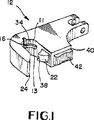
図1は、図2〜図5に示したような少なくとも1つ、好ましくは2つのソケット12を有する外科手術用牽引具の一好適例を示す。他の牽引具設計も、本発明のソケット12を利用できる。この設計のソケット12は、横側装填形式で結合ヘッド14を受容する。実際には、この好適実施例の場合、少なくとも1つの突起、例えば1つ以上のピンまたは棚状部分16が、ソケット穴(またはソケット室)18内に突出しているため、結合ヘッド14の頭部装填が防止される。
FIG. 1 shows one preferred embodiment of a surgical traction tool having at least one, preferably two
別の例では、例えば棚状部分16が設けられていない場合か、十分にソケット穴18内に突出していない場合か、その他の場合には、頭部装填が可能である。本件出願人による係属中の米国特許出願第60/327437号に図示され説明された結合ヘッドは、この好適例のソケット12と首尾よく協働する。棚状部分16は、好適には、ソケット穴の頂部11と底部13の間に設けられる。
In another example, for example, if the shelf-
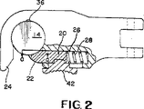
この好適例では、図2に示すように、ソケット穴内に結合ヘッドを固定するため、特許第6042540号に図示され説明されたような回転式カムの使用に代えて、直線運動する滑動子20が使用されている。滑動子20は、図3に示したロック位置と、図4に破線で示した非ロック位置との間で直線的に動くことができる。また、図4には、結合ヘッド14がソケットチャンバ18内の所定位置に「スナップ嵌入」される際に生じるであろう中間位置も示されている。これについては、後で詳しく説明する。
滑動子20は、ソケット穴18に対して外向きの第1面22を有する。この第1面22は、好適には凸面であり、それによって、従来は円筒形状である結合ヘッドがソケット穴18に向かって第1面22と誘導部24とに対して押しつけられる際に、滑動子20がスロット26内に偏位せしめられる。スロット26は、滑動子20または他の構成部材がソケット12から外側に突出することで何かを引っ掛けないように、滑動子20を受容する。
In this preferred embodiment, as shown in FIG. 2, instead of using a rotating cam as shown and described in US Pat. No. 6,042,540, a linearly moving
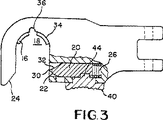
滑動子20は、図2に示すロック位置を占めるように、ばね28によって常時付勢されている。したがって、ソケット穴18内に押し込まれる結合ヘッド14が、ばね28の付勢力に勝った時、結合ヘッド14が、所定位置に「スナップ嵌入」される。なぜなら、結合ヘッドが滑動子20の先端30を通過すると、凹状の第2面に係合するからである。第2面を凹状にするのが有利と思われるのは、そうすることで、ソケット穴18の円形状が連続して、ソケット壁34に内接する円が第2面32に沿って連続するからである。さらに、この好適例の場合、第2面32を凹状にすることで、第2面32がソケット穴18内に突入しないようにできる。
The
この好適例では、滑動子20が、先行技術の場合のように、一部であってもソケット12内に突出しないように、特別に設計されている。滑動子20は、ソケット穴18内に結合ヘッド14を保持するために、ソケットに対して外側に配置される。実際に、特に滑動子20の第2面32がソケット壁34と等しい曲率の円弧を有する場合、滑動子20によりソケット穴18の画成が補足される。別例では、滑動子20がソケット穴18内に突出するだろう。
ソケット穴18に隣接して設けた切欠き36は、結合ヘッドのロックピンを受容する。さらに、先端30および/または第1面32にノッチ38が設けられ、該ノッチが、結合ヘッドの第2ロックピンを少なくとも部分的に受容することで、該ロックピンが滑動子20の方に回転しないように補助する。図示のノッチ38は、ロックピンを使用している場合、ロックピンが切欠き36およびノッチ38側に向けられると、結合ヘッド14が滑動子20側に回転しないように働く。
In this preferred embodiment, the
A
前記のとおり、結合ヘッド14を、ソケット穴18内にスナップ嵌入できるが、滑動子20はグリップ40で操作可能である。グリップ40は、好適には、操作し易いように、ギザ付きの表面42を有する。また、グリップ40は、使用者の親指または指を当てがい易いように、湾曲形状にすることができる。グリップ40を動かすと、滑動子20が動く。グリップ40は、ソケット12に沿って可動であり、ソケット12から離脱することはない。滑動子20は、スロット26内を直線的に移動可能である。
スロット26の形成を助けるために、誘導部24の穴あけ部分46によって、スロット26の通し機械加工ができる。したがって、縫合穴48がソケット胴部50に設けられる。図1に示したように、胴部50の頂部に沿った溝52により、アーム44がスロット26に接近可能である。同様な溝を、別のアームと共に胴部50の底部に沿って設けることができる。
As described above, the coupling head 14 can be snapped into the socket hole 18, but the
To assist in the formation of the
図5に示したような種類の外科手術用牽引具10は、図1〜図4に示したソケットを利用することになるだろう。特許第6042540号の図4に示されたような縦型牽引具を含む別の種類の牽引具およびその他の牽引具もまた、本発明のソケット構成を採用できる。
この好適例は、特許第6042540号に図示され説明された構成とは、多くの特徴が相違するものの、その多くの特徴を取り除き、本明細書で開示した多くの特徴を、首尾よく前記特許に示された構成に組み合わせることができる。
A surgical traction tool 10 of the kind shown in FIG. 5 would utilize the socket shown in FIGS. Another type of traction tool, including a vertical traction tool as shown in FIG. 4 of US Pat. No. 6,042,540, and other traction tools may also employ the socket configuration of the present invention.
Although this preferred embodiment differs from the configuration illustrated and described in US Pat. No. 6,042,540, many features are different, many features disclosed herein have been successfully incorporated into the patent. Can be combined with the configuration shown.
本明細書に開示した構造の多くの変形形態が、当業者に示唆されるだろう。しかしながら、本明細書の開示内容は、本発明の好適例に係わるもので、単なる説明目的の開示であり、本発明を制限するものとして解釈すべきではない。本発明の精神を逸脱することのないあらゆる変形形態は、特許請求の範囲の枠内に含まれる。 Many variations of the structures disclosed herein will be suggested to those skilled in the art. However, the disclosure of the present specification relates to a preferred example of the present invention, and is merely for the purpose of illustration and should not be construed as limiting the present invention. All modifications that do not depart from the spirit of the invention are within the scope of the claims.
Claims (16)
ロック位置または解放位置にあって、前記結合ヘッドを、ソケット穴に対して選択的に保持し、また、解放するように構成された直線的に変位可能な滑動子と、
前記結合ヘッドの頭部装填を防ぐために、前記ソケット穴内に突出する少なくとも1つの突出部とを含む外科手術用牽引具。A traction tool barrel having a lateral loadable socket hole for receiving a coupling head;
In the locked position or release position, the coupling head, and selectively retained to the socket hole, also the slide elements linearly displaceable configured to release,
Surgical traction tool including at least one protrusion projecting into the socket hole to prevent head loading of the coupling head .
結合ヘッドを受容する横側装填式ソケット穴を有する牽引具胴部と、
ロック位置または解放位置にあって、前記結合ヘッドをソケット穴に対して選択的に保持し、また、解放するように構成された直線的に変位可能な滑動子とを含み、
前記滑動子の先端にノッチが形成され、該ノッチが、前記結合ヘッドのロックピンを少なくとも部分的に受容するように構成されている外科手術用牽引具。 Surgical traction tool
A traction tool barrel having a lateral loadable socket hole for receiving a coupling head;
In the locked position or release position, the coupling head selectively holding the socket hole, also viewed contains a linearly displaceable slide elements that are configured to release,
A surgical traction tool wherein a notch is formed at a tip of the slider, the notch being configured to at least partially receive a locking pin of the coupling head .
結合ヘッドを受容する横側装填式ソケット穴を有する牽引具胴部と、A traction tool barrel having a lateral loadable socket hole for receiving a coupling head;
前記ソケット穴の背部にある縦方向の凹部と、A longitudinal recess in the back of the socket hole;
ロック位置または解放位置にあって、選択的に、前記結合ヘッドをソケット穴内に保持し、また、前記結合ヘッドをソケット穴から解放するように構成された直線的に変位可能な滑動子とを含み、A linearly displaceable slider configured to hold the coupling head in a socket hole and to release the coupling head from the socket hole in a locked or released position. ,
前記滑動子の先端に設けたノッチが、前記ロック位置において、前記ソケット穴の背部にある前記縦方向の凹部に対して前記ソケット穴を隔てて対向する位置にあることを特徴とする外科手術用牽引具。A notch provided at the tip of the slider is located at a position facing the longitudinal recess at the back of the socket hole with the socket hole therebetween, in the locked position. Towing tool.
前記ソケット胴部内のスロットと、
前記ソケット穴内の結合ヘッドを、選択的に保持し、また、解放するために、ロック位置と解放位置にて、少なくとも部分的に前記スロット内を移動するように構成された直線変位可能な滑動子とを含む外科手術用牽引具。A socket body having a side loadable socket hole for receiving a coupling head;
A slot in the socket body;
The coupling head of the socket hole, and selectively retained, and in order to release at the locking position and a release position, linear displaceable slide configured to move at least partially within the slot Surgical traction tool including a child.
Applications Claiming Priority (2)
| Application Number | Priority Date | Filing Date | Title |
|---|---|---|---|
| US10/117,929 US6733444B2 (en) | 2002-04-05 | 2002-04-05 | Side loading surgical retractor |
| PCT/US2003/010255 WO2003086203A1 (en) | 2002-04-05 | 2003-04-03 | Side loading surgical retractor |
Publications (2)
| Publication Number | Publication Date |
|---|---|
| JP2006505298A JP2006505298A (en) | 2006-02-16 |
| JP4347704B2 true JP4347704B2 (en) | 2009-10-21 |
Family
ID=28674313
Family Applications (1)
| Application Number | Title | Priority Date | Filing Date |
|---|---|---|---|
| JP2003583231A Expired - Fee Related JP4347704B2 (en) | 2002-04-05 | 2003-04-03 | Side-loading surgical traction tool |
Country Status (7)
| Country | Link |
|---|---|
| US (1) | US6733444B2 (en) |
| EP (1) | EP1494591B1 (en) |
| JP (1) | JP4347704B2 (en) |
| AU (1) | AU2003237795B2 (en) |
| CA (1) | CA2481190C (en) |
| ES (1) | ES2418363T3 (en) |
| WO (1) | WO2003086203A1 (en) |
Families Citing this family (59)
| Publication number | Priority date | Publication date | Assignee | Title |
|---|---|---|---|---|
| US7887539B2 (en) | 2003-01-24 | 2011-02-15 | Depuy Spine, Inc. | Spinal rod approximators |
| US7988698B2 (en) * | 2003-01-28 | 2011-08-02 | Depuy Spine, Inc. | Spinal rod approximator |
| US20040267275A1 (en) * | 2003-06-26 | 2004-12-30 | Cournoyer John R. | Spinal implant holder and rod reduction systems and methods |
| US7481766B2 (en) * | 2003-08-14 | 2009-01-27 | Synthes (U.S.A.) | Multiple-blade retractor |
| US7297107B1 (en) | 2003-09-17 | 2007-11-20 | Minnesota Scientific, Inc. | Fulcrum wedge clamp |
| US20060200005A1 (en) * | 2003-09-17 | 2006-09-07 | Levahn Intellectual Property Holding Company, Llc | Low profile, handle-in-between surgical scissors clamp |
| US7320666B2 (en) * | 2003-09-17 | 2008-01-22 | Minnesota Scientific, Inc. | Fulcrum wedge clamp |
| US7097616B2 (en) * | 2003-10-08 | 2006-08-29 | Minnesota Scientific, Inc. | Surgical clamp |
| WO2005037089A1 (en) * | 2003-10-17 | 2005-04-28 | Minnesota Scientific, Inc. | Articulated retractor blade holder |
| US7842044B2 (en) | 2003-12-17 | 2010-11-30 | Depuy Spine, Inc. | Instruments and methods for bone anchor engagement and spinal rod reduction |
| US7824411B2 (en) | 2003-12-17 | 2010-11-02 | Depuy Spine, Inc. | Instruments and methods for bone anchor engagement and spinal rod reduction |
| WO2005069803A2 (en) * | 2004-01-12 | 2005-08-04 | Minnesota Scientific, Inc. | Threaded fulcrum clamp |
| US7666189B2 (en) * | 2004-09-29 | 2010-02-23 | Synthes Usa, Llc | Less invasive surgical system and methods |
| ATE524121T1 (en) | 2004-11-24 | 2011-09-15 | Abdou Samy | DEVICES FOR PLACING AN ORTHOPEDIC INTERVERTEBRAL IMPLANT |
| US7473223B2 (en) * | 2005-02-07 | 2009-01-06 | Peter Edward Fetzer | Push-button activated grasper for surgical retractor |
| US7951172B2 (en) | 2005-03-04 | 2011-05-31 | Depuy Spine Sarl | Constrained motion bone screw assembly |
| US7951175B2 (en) | 2005-03-04 | 2011-05-31 | Depuy Spine, Inc. | Instruments and methods for manipulating a vertebra |
| US20060293692A1 (en) | 2005-06-02 | 2006-12-28 | Whipple Dale E | Instruments and methods for manipulating a spinal fixation element |
| US7588537B2 (en) * | 2005-09-07 | 2009-09-15 | West Coast Surgical, Llc. | Connector with safety latch for a surgical retractor |
| US7569014B2 (en) * | 2005-09-07 | 2009-08-04 | West Coast Surgical, Llc | Connector for a surgical retractor |
| US8172847B2 (en) * | 2007-03-29 | 2012-05-08 | Depuy Spine, Inc. | In-line rod reduction device and methods |
| US7887541B2 (en) | 2007-07-26 | 2011-02-15 | Depuy Spine, Inc. | Spinal rod reduction instruments and methods for use |
| US8790348B2 (en) | 2007-09-28 | 2014-07-29 | Depuy Spine, Inc. | Dual pivot instrument for reduction of a fixation element and method of use |
| US8709015B2 (en) | 2008-03-10 | 2014-04-29 | DePuy Synthes Products, LLC | Bilateral vertebral body derotation system |
| US8608746B2 (en) | 2008-03-10 | 2013-12-17 | DePuy Synthes Products, LLC | Derotation instrument with reduction functionality |
| US10973556B2 (en) | 2008-06-17 | 2021-04-13 | DePuy Synthes Products, Inc. | Adjustable implant assembly |
| US8206394B2 (en) | 2009-05-13 | 2012-06-26 | Depuy Spine, Inc. | Torque limited instrument for manipulating a spinal rod relative to a bone anchor |
| WO2011059491A1 (en) | 2009-11-10 | 2011-05-19 | Nuvasive Inc. | Method and apparatus for performing spinal surgery |
| US8764806B2 (en) | 2009-12-07 | 2014-07-01 | Samy Abdou | Devices and methods for minimally invasive spinal stabilization and instrumentation |
| US8636655B1 (en) | 2010-01-19 | 2014-01-28 | Ronald Childs | Tissue retraction system and related methods |
| WO2012078893A1 (en) * | 2010-12-09 | 2012-06-14 | Extraortho, Inc. | External fixation clamp with cam driven jaw |
| US9277906B2 (en) * | 2011-04-19 | 2016-03-08 | NSI-US, Inc. | Quick-release handle for retractor blades |
| US8900137B1 (en) | 2011-04-26 | 2014-12-02 | Nuvasive, Inc. | Cervical retractor |
| US8974381B1 (en) | 2011-04-26 | 2015-03-10 | Nuvasive, Inc. | Cervical retractor |
| US9307972B2 (en) | 2011-05-10 | 2016-04-12 | Nuvasive, Inc. | Method and apparatus for performing spinal fusion surgery |
| US10166018B2 (en) | 2011-08-19 | 2019-01-01 | Nuvasive, Inc. | Surgical retractor system and methods of use |
| US9113853B1 (en) | 2011-08-31 | 2015-08-25 | Nuvasive, Inc. | Systems and methods for performing spine surgery |
| US9549724B2 (en) | 2011-09-13 | 2017-01-24 | NSI-US, Inc. | Adaptor for surgical retractor blades |
| US8845728B1 (en) | 2011-09-23 | 2014-09-30 | Samy Abdou | Spinal fixation devices and methods of use |
| US20130226240A1 (en) | 2012-02-22 | 2013-08-29 | Samy Abdou | Spinous process fixation devices and methods of use |
| US9198767B2 (en) | 2012-08-28 | 2015-12-01 | Samy Abdou | Devices and methods for spinal stabilization and instrumentation |
| US9320617B2 (en) | 2012-10-22 | 2016-04-26 | Cogent Spine, LLC | Devices and methods for spinal stabilization and instrumentation |
| GB2598671B (en) | 2014-08-13 | 2022-07-13 | Nuvasive Inc | Minimally disruptive retractor and associated methods for spinal surgery |
| US9848863B2 (en) | 2015-02-25 | 2017-12-26 | Globus Medical, Inc | Surgical retractor systems and methods |
| US9700293B2 (en) | 2015-08-18 | 2017-07-11 | Globus Medical, Inc. | Devices and systems for surgical retraction |
| US10857003B1 (en) | 2015-10-14 | 2020-12-08 | Samy Abdou | Devices and methods for vertebral stabilization |
| US10744000B1 (en) | 2016-10-25 | 2020-08-18 | Samy Abdou | Devices and methods for vertebral bone realignment |
| US10973648B1 (en) | 2016-10-25 | 2021-04-13 | Samy Abdou | Devices and methods for vertebral bone realignment |
| WO2019055173A1 (en) * | 2017-09-18 | 2019-03-21 | Thompson Surgical Instruments, Inc. | Retractor system and side load connector for surgical retractor blade |
| US10966762B2 (en) | 2017-12-15 | 2021-04-06 | Medos International Sarl | Unilateral implant holders and related methods |
| US11179248B2 (en) | 2018-10-02 | 2021-11-23 | Samy Abdou | Devices and methods for spinal implantation |
| DE102018128841A1 (en) * | 2018-11-16 | 2020-05-20 | Olympus Winter & Ibe Gmbh | Medical instrument holder |
| US11291482B2 (en) | 2019-03-21 | 2022-04-05 | Medos International Sarl | Rod reducers and related methods |
| USD1004774S1 (en) | 2019-03-21 | 2023-11-14 | Medos International Sarl | Kerrison rod reducer |
| US11291481B2 (en) | 2019-03-21 | 2022-04-05 | Medos International Sarl | Rod reducers and related methods |
| CH716837A1 (en) * | 2019-11-25 | 2021-05-31 | Vitra Patente Ag | Wind bandage and furniture kit. |
| CH716838A1 (en) * | 2019-11-25 | 2021-05-31 | Vitra Patente Ag | Traverse, traverse set and furniture kit. |
| US11806002B2 (en) | 2021-02-01 | 2023-11-07 | Thompson Surgical Instruments, Inc. | Retractor system and retractor arm with detachable handle |
| FR3125735B1 (en) * | 2021-07-28 | 2023-07-14 | Ostium Group | TOOL HOLDER FOR MODULAR TOOL |
Family Cites Families (18)
| Publication number | Priority date | Publication date | Assignee | Title |
|---|---|---|---|---|
| US505281A (en) * | 1893-09-19 | smith | ||
| US479146A (en) * | 1892-07-19 | Thill- coupling | ||
| US838767A (en) * | 1906-06-25 | 1906-12-18 | Christopher C Bradley | Thill-coupling. |
| US1185292A (en) * | 1915-12-27 | 1916-05-30 | Oscar T Dean | Retractor for dental surgery. |
| US2845307A (en) * | 1954-04-19 | 1958-07-29 | Superior Scaffold Company | Detachable coupling for scaffold elements |
| US3227496A (en) * | 1964-02-11 | 1966-01-04 | Rubon Inc | Detachable connector |
| US4544324A (en) * | 1983-04-29 | 1985-10-01 | Kenhar Products Incorporated | Quickchange fork |
| JPH068811U (en) * | 1992-07-08 | 1994-02-04 | 吉田工業株式会社 | Eggplant ring |
| US6042540A (en) * | 1997-08-18 | 2000-03-28 | Pacific Surgical Innovations, Inc. | Side-loading surgical retractor |
| US5993385A (en) * | 1997-08-18 | 1999-11-30 | Johnston; Terry | Self-aligning side-loading surgical retractor |
| US6206826B1 (en) * | 1997-12-18 | 2001-03-27 | Sdgi Holdings, Inc. | Devices and methods for percutaneous surgery |
| US5931777A (en) * | 1998-03-11 | 1999-08-03 | Sava; Gerard A. | Tissue retractor and method for use |
| US5984865A (en) * | 1998-09-15 | 1999-11-16 | Thompson Surgical Instruments, Inc. | Surgical retractor having locking interchangeable blades |
| EP1035272B1 (en) * | 1999-03-05 | 2003-08-13 | Hasegawa Kogyo Co., Ltd. | Hook device |
| EP1046825A3 (en) * | 1999-04-23 | 2002-04-17 | Piolax Inc. | Fastening structure for fixing an article on a board via a through-hole, and holder with such a fastening structure |
| US6206828B1 (en) * | 1999-06-08 | 2001-03-27 | John T. M. Wright | Sternal retractor with changeable blades and blade latch mechanism |
| US6524310B1 (en) * | 2000-08-18 | 2003-02-25 | Blackstone Medical, Inc. | Surgical cross-connecting apparatus having locking lever |
| DE10048790A1 (en) * | 2000-10-02 | 2002-04-25 | Aesculap Ag & Co Kg | Device for creating percutaneous access |
-
2002
- 2002-04-05 US US10/117,929 patent/US6733444B2/en not_active Expired - Lifetime
-
2003
- 2003-04-03 EP EP03736452A patent/EP1494591B1/en not_active Expired - Lifetime
- 2003-04-03 JP JP2003583231A patent/JP4347704B2/en not_active Expired - Fee Related
- 2003-04-03 AU AU2003237795A patent/AU2003237795B2/en not_active Ceased
- 2003-04-03 WO PCT/US2003/010255 patent/WO2003086203A1/en active Application Filing
- 2003-04-03 CA CA2481190A patent/CA2481190C/en not_active Expired - Fee Related
- 2003-04-03 ES ES03736452T patent/ES2418363T3/en not_active Expired - Lifetime
Also Published As
| Publication number | Publication date |
|---|---|
| CA2481190C (en) | 2013-01-08 |
| ES2418363T3 (en) | 2013-08-13 |
| AU2003237795A1 (en) | 2003-10-27 |
| JP2006505298A (en) | 2006-02-16 |
| US20030191370A1 (en) | 2003-10-09 |
| EP1494591A1 (en) | 2005-01-12 |
| EP1494591A4 (en) | 2010-05-26 |
| EP1494591B1 (en) | 2013-04-03 |
| CA2481190A1 (en) | 2003-10-23 |
| AU2003237795B2 (en) | 2008-06-26 |
| US6733444B2 (en) | 2004-05-11 |
| WO2003086203A1 (en) | 2003-10-23 |
Similar Documents
| Publication | Publication Date | Title |
|---|---|---|
| JP4347704B2 (en) | Side-loading surgical traction tool | |
| JP5052249B2 (en) | Cleaning tool | |
| US6887197B2 (en) | Side loading surgical retractor having offset cavity | |
| JP5188820B2 (en) | razor | |
| US8136251B2 (en) | Hand tool | |
| WO2015056621A1 (en) | Razor with detachable replacement blade | |
| EP1232841B1 (en) | Cutter cassette and cutting device using the same | |
| KR102615110B1 (en) | Razor handle with locking and unlocking mechanism for engaging and disengaging cartridges | |
| WO2010065219A2 (en) | Hub and handle design for carpal tunnel release tool | |
| EP1637287A1 (en) | Hand tool having an adjustable head with a joint mechanism | |
| JP4468007B2 (en) | Reciprocating saw | |
| US7040208B2 (en) | Cutter cassette and cutting device | |
| CN111529066A (en) | Instrument poking clamp for surgical robot | |
| ES2335150T3 (en) | HAND OF SURGICAL INSTRUMENT AND SURGICAL INSTRUMENT. | |
| EP1860968A2 (en) | Cufflink | |
| US20020153395A1 (en) | Apparatus and method for controlling use of a knife | |
| JP5260252B2 (en) | Bone dimension measuring instrument | |
| US20180141371A1 (en) | Pen cartridge | |
| JP2000326303A (en) | Blade plate attaching and detaching structure | |
| JP2006081611A (en) | Spare blade and holder for reciprocating saw | |
| JP2016016174A (en) | Handheld tool | |
| TWI325806B (en) | ||
| JP3701552B2 (en) | Blade mounting device for reciprocating cutting tool | |
| JP7365508B2 (en) | locking device | |
| JP7086337B2 (en) | Dental tool holder |
Legal Events
| Date | Code | Title | Description |
|---|---|---|---|
| A131 | Notification of reasons for refusal |
Free format text: JAPANESE INTERMEDIATE CODE: A131 Effective date: 20081205 |
|
| A601 | Written request for extension of time |
Free format text: JAPANESE INTERMEDIATE CODE: A601 Effective date: 20090305 |
|
| A602 | Written permission of extension of time |
Free format text: JAPANESE INTERMEDIATE CODE: A602 Effective date: 20090312 |
|
| A601 | Written request for extension of time |
Free format text: JAPANESE INTERMEDIATE CODE: A601 Effective date: 20090406 |
|
| A602 | Written permission of extension of time |
Free format text: JAPANESE INTERMEDIATE CODE: A602 Effective date: 20090413 |
|
| A601 | Written request for extension of time |
Free format text: JAPANESE INTERMEDIATE CODE: A601 Effective date: 20090507 |
|
| A602 | Written permission of extension of time |
Free format text: JAPANESE INTERMEDIATE CODE: A602 Effective date: 20090514 |
|
| A521 | Request for written amendment filed |
Free format text: JAPANESE INTERMEDIATE CODE: A523 Effective date: 20090605 |
|
| TRDD | Decision of grant or rejection written | ||
| A01 | Written decision to grant a patent or to grant a registration (utility model) |
Free format text: JAPANESE INTERMEDIATE CODE: A01 Effective date: 20090710 |
|
| A01 | Written decision to grant a patent or to grant a registration (utility model) |
Free format text: JAPANESE INTERMEDIATE CODE: A01 |
|
| A61 | First payment of annual fees (during grant procedure) |
Free format text: JAPANESE INTERMEDIATE CODE: A61 Effective date: 20090716 |
|
| R150 | Certificate of patent or registration of utility model |
Ref document number: 4347704 Country of ref document: JP Free format text: JAPANESE INTERMEDIATE CODE: R150 Free format text: JAPANESE INTERMEDIATE CODE: R150 |
|
| FPAY | Renewal fee payment (event date is renewal date of database) |
Free format text: PAYMENT UNTIL: 20120724 Year of fee payment: 3 |
|
| FPAY | Renewal fee payment (event date is renewal date of database) |
Free format text: PAYMENT UNTIL: 20120724 Year of fee payment: 3 |
|
| FPAY | Renewal fee payment (event date is renewal date of database) |
Free format text: PAYMENT UNTIL: 20130724 Year of fee payment: 4 |
|
| R250 | Receipt of annual fees |
Free format text: JAPANESE INTERMEDIATE CODE: R250 |
|
| R250 | Receipt of annual fees |
Free format text: JAPANESE INTERMEDIATE CODE: R250 |
|
| R250 | Receipt of annual fees |
Free format text: JAPANESE INTERMEDIATE CODE: R250 |
|
| R250 | Receipt of annual fees |
Free format text: JAPANESE INTERMEDIATE CODE: R250 |
|
| R250 | Receipt of annual fees |
Free format text: JAPANESE INTERMEDIATE CODE: R250 |
|
| R250 | Receipt of annual fees |
Free format text: JAPANESE INTERMEDIATE CODE: R250 |
|
| R250 | Receipt of annual fees |
Free format text: JAPANESE INTERMEDIATE CODE: R250 |
|
| R250 | Receipt of annual fees |
Free format text: JAPANESE INTERMEDIATE CODE: R250 |
|
| R250 | Receipt of annual fees |
Free format text: JAPANESE INTERMEDIATE CODE: R250 |
|
| R250 | Receipt of annual fees |
Free format text: JAPANESE INTERMEDIATE CODE: R250 |
|
| LAPS | Cancellation because of no payment of annual fees |