EP1494323B1 - Process for manufacturing insulated conductive elements of a rotating electrical collector and rotating electrical collector with the electric conductive elements - Google Patents
Process for manufacturing insulated conductive elements of a rotating electrical collector and rotating electrical collector with the electric conductive elements Download PDFInfo
- Publication number
- EP1494323B1 EP1494323B1 EP04291564A EP04291564A EP1494323B1 EP 1494323 B1 EP1494323 B1 EP 1494323B1 EP 04291564 A EP04291564 A EP 04291564A EP 04291564 A EP04291564 A EP 04291564A EP 1494323 B1 EP1494323 B1 EP 1494323B1
- Authority
- EP
- European Patent Office
- Prior art keywords
- electrically conductive
- zone
- enamel
- carrier structure
- collector
- Prior art date
- Legal status (The legal status is an assumption and is not a legal conclusion. Google has not performed a legal analysis and makes no representation as to the accuracy of the status listed.)
- Not-in-force
Links
Images

Classifications
-
- H—ELECTRICITY
- H01—ELECTRIC ELEMENTS
- H01R—ELECTRICALLY-CONDUCTIVE CONNECTIONS; STRUCTURAL ASSOCIATIONS OF A PLURALITY OF MUTUALLY-INSULATED ELECTRICAL CONNECTING ELEMENTS; COUPLING DEVICES; CURRENT COLLECTORS
- H01R39/00—Rotary current collectors, distributors or interrupters
- H01R39/02—Details for dynamo electric machines
- H01R39/38—Brush holders
- H01R39/39—Brush holders wherein the brush is fixedly mounted in the holder
-
- H—ELECTRICITY
- H01—ELECTRIC ELEMENTS
- H01R—ELECTRICALLY-CONDUCTIVE CONNECTIONS; STRUCTURAL ASSOCIATIONS OF A PLURALITY OF MUTUALLY-INSULATED ELECTRICAL CONNECTING ELEMENTS; COUPLING DEVICES; CURRENT COLLECTORS
- H01R4/00—Electrically-conductive connections between two or more conductive members in direct contact, i.e. touching one another; Means for effecting or maintaining such contact; Electrically-conductive connections having two or more spaced connecting locations for conductors and using contact members penetrating insulation
- H01R4/70—Insulation of connections
-
- Y—GENERAL TAGGING OF NEW TECHNOLOGICAL DEVELOPMENTS; GENERAL TAGGING OF CROSS-SECTIONAL TECHNOLOGIES SPANNING OVER SEVERAL SECTIONS OF THE IPC; TECHNICAL SUBJECTS COVERED BY FORMER USPC CROSS-REFERENCE ART COLLECTIONS [XRACs] AND DIGESTS
- Y10—TECHNICAL SUBJECTS COVERED BY FORMER USPC
- Y10T—TECHNICAL SUBJECTS COVERED BY FORMER US CLASSIFICATION
- Y10T29/00—Metal working
- Y10T29/49—Method of mechanical manufacture
- Y10T29/49002—Electrical device making
- Y10T29/49009—Dynamoelectric machine
-
- Y—GENERAL TAGGING OF NEW TECHNOLOGICAL DEVELOPMENTS; GENERAL TAGGING OF CROSS-SECTIONAL TECHNOLOGIES SPANNING OVER SEVERAL SECTIONS OF THE IPC; TECHNICAL SUBJECTS COVERED BY FORMER USPC CROSS-REFERENCE ART COLLECTIONS [XRACs] AND DIGESTS
- Y10—TECHNICAL SUBJECTS COVERED BY FORMER USPC
- Y10T—TECHNICAL SUBJECTS COVERED BY FORMER US CLASSIFICATION
- Y10T29/00—Metal working
- Y10T29/49—Method of mechanical manufacture
- Y10T29/49002—Electrical device making
- Y10T29/49117—Conductor or circuit manufacturing
- Y10T29/49169—Assembling electrical component directly to terminal or elongated conductor
-
- Y—GENERAL TAGGING OF NEW TECHNOLOGICAL DEVELOPMENTS; GENERAL TAGGING OF CROSS-SECTIONAL TECHNOLOGIES SPANNING OVER SEVERAL SECTIONS OF THE IPC; TECHNICAL SUBJECTS COVERED BY FORMER USPC CROSS-REFERENCE ART COLLECTIONS [XRACs] AND DIGESTS
- Y10—TECHNICAL SUBJECTS COVERED BY FORMER USPC
- Y10T—TECHNICAL SUBJECTS COVERED BY FORMER US CLASSIFICATION
- Y10T29/00—Metal working
- Y10T29/49—Method of mechanical manufacture
- Y10T29/49002—Electrical device making
- Y10T29/49117—Conductor or circuit manufacturing
- Y10T29/49204—Contact or terminal manufacturing
- Y10T29/49208—Contact or terminal manufacturing by assembling plural parts
- Y10T29/4921—Contact or terminal manufacturing by assembling plural parts with bonding
- Y10T29/49211—Contact or terminal manufacturing by assembling plural parts with bonding of fused material
Definitions
- the invention relates to a method of manufacturing electrically conductive elements isolated from rotating collector and a rotating collector for the spatial domain comprising these electrically conductive elements.
- Rotary manifolds are used to transfer electrical power or signals between moving parts relative to each other. They generally comprise a fixed carrier structure, called a stator, supporting conductive wires called eyelashes, and a rotating part, the rotor, carrying a plurality of cylindrical conductive tracks on which the ends of the eyelashes are in electrical contact.
- the eyelashes on the one hand, the tracks on the other hand, are connected to electrical conductors through which the power or the signals pass.
- the conductive yarns or eyelashes are generally made of copper, gold, platinum, copper alloy, gold alloy or platinum alloy.
- the power or the electrical signals are transferred from the fixed part to the mobile part by brushes which rub with a cylindrical or flat conductive track. These brushes are mounted on flexible brush holders.
- the eyelashes and the brush supports constitute electrically conductive elements within the meaning of the present invention. Since they are drivers, they must be isolated from each other. This isolation is currently performed by spacing the eyelashes or brush holders between them. This solution has the disadvantage of being sensitive to pollution by particles or a conductive plasma which can cause short circuits between eyelashes or adjacent brush holders. In the space domain to which the invention applies, such risks are not permissible in view of the required reliability.
- the document DE-1,613,183 describes elastic arms. At their end is brazed pad in rubbing contact on a conductive track.
- the elastic element is constituted by the conductor itself which is surrounded by an insulating sheath of flexible synthetic material.
- an insulating sheath of flexible synthetic material usually of the order of 100 .mu.m.
- the present invention relates to a method of manufacturing insulated electrically conductive elements, particularly eyelashes and collector brush supports and a rotating collector comprising these eyelashes and / or these brush holders which overcome this disadvantage.
- an electrically conductive element for the transfer of an electric current between two moving parts relative to each other.
- This electrically conductive element is covered with at least one layer of insulating enamel electrically, with the exception of a zone of electrical continuity.
- the electrical continuity zone is a friction zone in contact with a conductive track that moves relative thereto.
- the electrical continuity zone is a mounting zone for the brushes, which are in contact with a conductive track that moves relative to them.
- the electrically conductive elements are mounted on a carrier structure of the collector after the step (c) of treatment of the electrical continuity zone.
- the electrically conductive elements are mounted on a carrier structure of the collector before the step (c) of treatment of the electrical continuity zone.
- the enamel layer is removed by etching, thermal or mechanical etching.
- the enamel layer or layers are chosen from the group comprising polyvinyls, polyurethanes, polyesters, polyester imides, polyamide imides, polyimides.
- the electrically conductive element may comprise several layers of enamel of the same chemical nature or of different natures.
- the invention also relates to a collector comprising a first part and a second part moving relative to each other, one of these parts supporting a plurality of electrically conductive elements made according to the method of the invention.
- the electrically conductive elements are covered with at least one layer of electrically insulating enamel with the exception of a zone of electrical continuity zone.
- the collector comprises a fixed carrier structure and a rotor comprising conductive tracks and rotatably mounted in the carrier structure, the carrier structure supporting a plurality of electrically conductive cilia each having a contact zone applied to a rotor track.
- the collector comprises a fixed carrier structure and a rotor comprising cylindrical or flat conductive tracks and rotatably mounted in the carrier structure, the carrier structure supporting a plurality of electrically conductive brush supports each having a mounting zone of brushes in contact on a rotor track.
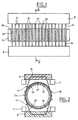
- the collector shown on Figures 1 and 2 comprises a fixed support structure 2 which supports two eyelash supports 8.
- the eyelashes 14 comprise a flat part 15 held in an eyelash holder 8 by a cover or by a resin filling and two free ends 20 arranged on either side
- the eyelashes are made of copper or copper alloy, or other good conducting metals such as gold, silver, platinum or one of their alloys.
- the eyelashes 14 are made of gold alloy and have a circular section. However, it is understood that in the context of the invention, they may have another section, for example square, rectangular or other.
- Each eyelash support 8 is fixed, for example by screws (not shown), on two flats of the supporting structure 2.
- a rotor 24 is rotatably mounted inside the supporting structure 2.
- the rotor 24 is guided in rotation at its ends in bearings (not shown). It comprises a bearing 28 on which are threaded a series of rings. Some of these rings, such as rings 32 and 34 (see figure 3 ), are simple spacers.
- Other rings 37 have an L-shaped section in which conductive rings 33 are housed. Between the rings 34 and 37 made of an electrically insulating material is formed a set 36.
- a conductive ring 33 made for example of a copper alloy, gold or golden brass, is mounted on each ring 37.
- the rings 33 have a semi-circular groove or other shape which receives an eyelash 14.
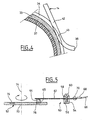
- the ends 20 of the eyelashes comprise a curved portion 38 intended to facilitate their insertion into the grooves 35.
- the eyelashes 14 are preloaded: this means that their free end 20 is applied to the tracks with a certain support force, called preload , so as to ensure good contact between the eyelashes and the track on which they are applied.
- the pre-charge is adjustable.
- the eyelashes are glazed prior to their use in the collector. This avoids the pollution of the collector. In addition, this allows their control before use.
- the enameling operation can be carried out according to a known method, in particular by soaking the eyelashes in a solution of an electrically insulating material, then by cooking in an enameling furnace, such as that described in the document EP-0 875 299 .
- the enameled conductor runs continuously along an enameling line.
- the enameling line generally comprises an applicator for depositing on the wire a solution of oligomers or prepolymers, constituting the insulating material, in a solvent. Additives are usually added to the solution (catalyst, adhesion promoter, etc.).
- This applicator is followed by an enameling furnace comprising a solvent evaporation zone (150 ° C.-350 ° C.) and a polymerization and crosslinking zone of the electrically insulating material (350 ° C.-550 ° C.).
- an enameling furnace comprising a solvent evaporation zone (150 ° C.-350 ° C.) and a polymerization and crosslinking zone of the electrically insulating material (350 ° C.-550 ° C.).
- the conductive wire is then cut into sections to form the eyelashes 14.
- the electrical continuity zone is treated to remove enamel for example by dipping.
- the enamel removal operation is preferably carried out after mounting the eyelashes 14 in the carrier structure 2.
- FIG. 5 a second embodiment of a collector according to the invention. It comprises a fixed part 50 and a mobile part 52.
- the fixed part comprises a support 54, for example made of aluminum, consisting of two parts 56 and 58 clamped by a screw 60 and between which is disposed a brush holder 62 which constitutes a electrically conductive element within the meaning of the invention.
- the brush holder 62 is constituted by an electrically conductive flexible blade of flattened rectangular section made, for example, of copper or a copper alloy. At its free end, it carries one or more brushes 64 of carbon or other conductive material.
- a wire electrical conductor 66 which terminates in a lug 68 fixed to the blade 62, for example by means of a rivet 70.
- An insulation (not shown) is provided between the support 54 and the brush holder 62.
- the movable portion 52 is constituted by a disc 72 movable in rotation about an axis 74.
- the disc 72 comprises circular conductive tracks 76, made for example of silver.
- the broom 64 rubs on the track 76.
- the broom support 62 is pre-loaded to apply the broom 64 with a given force on the track 76.
- the flexible blade 62 is electrically insulated by one or more layers of enamel (not shown). These enamel layers can be of the same chemical nature or of different chemical natures. They are advantageously deposited in several successive layers of a few microns thick.
- the enamel layer is locally removed in the contact zone 65 between the brush 64 and the flexible blade 62 to ensure the continuity of the electrical transmission.
- the enamel layer is also removed at the contact between the flexible blade 62 and the lug 68 of the electrical conductor 66.
- the enamel used may be polyvinyl type, polyurethane, polyester, polyester imide, polyamide imide, polyimide or other.
- the preload adjustment is done after the eyelashes or brush holders have been enamelled, so that the stiffness of the enamel is taken into account when adjusting the preload.
- the eyelashes or brush holders Due to the presence of the enamel layer 42, a double insulation of the eyelashes or brush holders in the power or signal collector is achieved.
- the eyelashes or brush holders are isolated by spacing them, but furthermore they are isolated by the presence of an enamel layer on each of them.
- the preload is not disturbed by the presence of the enamel layer.
- the temperature resistance is better than that of an adhesive or a sheath.
- the invention does not apply exclusively to the rotary manifolds which have just been described, but to all types of collectors in which conductive elements transmit signals or electrical power by friction between a part fixed and a moving part, for example by friction on a track made on a record or on a turntable.
- the invention also applies to a collector in which the tracks are fixed and the conductive elements are mounted on a rotating part relative to the tracks.
Abstract
Description
L'invention concerne un procédé de fabrication d'éléments électriquement conducteurs isolés de collecteur tournant et un collecteur tournant destiné au domaine spatial comportant ces éléments électriquement conducteurs.The invention relates to a method of manufacturing electrically conductive elements isolated from rotating collector and a rotating collector for the spatial domain comprising these electrically conductive elements.
Les collecteurs tournants sont utilisés pour transférer une puissance électrique ou des signaux entre des pièces mobiles l'une par rapport à l'autre. Ils comprennent généralement une structure porteuse fixe, appelée stator, supportant des fils conducteurs appelés cils, et une partie tournante, le rotor, portant une pluralité de pistes conductrices cylindriques sur lesquelles les extrémités des cils sont en contact électrique. Les cils d'une part, les pistes d'autre part, sont reliés à des conducteurs électriques par lesquels transitent la puissance ou les signaux. Les fils conducteurs ou cils sont généralement en cuivre, en or, en platine, en alliage de cuivre, en alliage d'or ou en alliage de platine.Rotary manifolds are used to transfer electrical power or signals between moving parts relative to each other. They generally comprise a fixed carrier structure, called a stator, supporting conductive wires called eyelashes, and a rotating part, the rotor, carrying a plurality of cylindrical conductive tracks on which the ends of the eyelashes are in electrical contact. The eyelashes on the one hand, the tracks on the other hand, are connected to electrical conductors through which the power or the signals pass. The conductive yarns or eyelashes are generally made of copper, gold, platinum, copper alloy, gold alloy or platinum alloy.
Dans d'autres types de collecteurs, la puissance ou les signaux électriques sont transférés de la partie fixe à la partie mobile par des balais qui frottent avec une piste conductrice cylindrique ou plane. Ces balais sont montés sur des supports de balais flexibles.In other types of collectors, the power or the electrical signals are transferred from the fixed part to the mobile part by brushes which rub with a cylindrical or flat conductive track. These brushes are mounted on flexible brush holders.
Les cils et les supports de balais constituent des éléments électriquement conducteurs au sens de la présente invention. Étant donné qu'ils sont conducteurs, ils doivent être isolés les uns des autres. Cet isolement est actuellement réalisé par un espacement des cils ou des supports de balais entre eux. Cette solution présente l'inconvénient d'être sensible à une pollution par des particules ou par un plasma conducteur qui peuvent engendrer des courts-circuits entre des cils ou des supports de balais voisins. Dans le domaine spatial auquel l'invention s'applique, de tels risques ne sont pas admissibles compte tenu de la fiabilité requise.The eyelashes and the brush supports constitute electrically conductive elements within the meaning of the present invention. Since they are drivers, they must be isolated from each other. This isolation is currently performed by spacing the eyelashes or brush holders between them. This solution has the disadvantage of being sensitive to pollution by particles or a conductive plasma which can cause short circuits between eyelashes or adjacent brush holders. In the space domain to which the invention applies, such risks are not permissible in view of the required reliability.
Le document
Le document
Cependant la présence autour du conducteur d'une gaine isolante d'une certaine épaisseur (habituellement de l'ordre de 100µm), perturbe la force d'application des bras sur la piste conductrice. En outre dans le cas d'une utilisation dans le domaine spatial, le matériau isolant doit conserver une bonne tenue mécanique à température élevée.The document
However, the presence around the conductor of an insulating sheath of a certain thickness (usually of the order of 100 .mu.m), disrupts the force of application of the arms on the conductive track. In addition, in the case of use in the spatial field, the insulating material must maintain a good mechanical strength at high temperature.
La présente invention a pour objet un procédé de fabrication d'éléments électriquement conducteurs isolés, particulièrement des cils et des supports de balais de collecteur et un collecteur tournant comportant ces cils et/ou ces supports de balais qui remédient à cet inconvénient.The present invention relates to a method of manufacturing insulated electrically conductive elements, particularly eyelashes and collector brush supports and a rotating collector comprising these eyelashes and / or these brush holders which overcome this disadvantage.
Ces buts sont atteints, conformément à l'invention, par un élément électriquement conducteur pour le transfert d'un courant électrique entre deux parties en mouvement l'une par rapport à l'autre. Cet élément électriquement conducteur est recouvert d'au moins une couche d'émail isolant électriquement, à l'exception d'une zone de continuité électrique.These objects are achieved, according to the invention, by an electrically conductive element for the transfer of an electric current between two moving parts relative to each other. This electrically conductive element is covered with at least one layer of insulating enamel electrically, with the exception of a zone of electrical continuity.
Dans le cas d'un cil, la zone de continuité électrique est une zone de frottement en contact avec une piste conductrice qui se déplace par rapport à lui. Dans le cas d'un support de balais, la zone de continuité électrique est une zone de montage des balais, lesquels sont en contact avec une piste conductrice qui se déplace par rapport à eux.In the case of an eyelash, the electrical continuity zone is a friction zone in contact with a conductive track that moves relative thereto. In the case of a brush holder, the electrical continuity zone is a mounting zone for the brushes, which are in contact with a conductive track that moves relative to them.
Selon l'invention, le procédé de fabrication comprend les étapes suivantes :
- (a) on recouvre l'élément électriquement conducteur d'une couche ou de plusieurs couches d'un matériau isolant électriquement,
- (b) on cuit ledit élément recouvert afin de réticuler ledit matériau pour former une ou plusieurs couches d'émail,
- (c) on traite la zone de continuité électrique des éléments électriquement conducteurs afin d'en retirer la ou les couches d'émail.
- (a) covering the electrically conductive element with a layer or layers of an electrically insulating material,
- (b) baking said coated member to crosslink said material to form one or more enamel layers,
- (c) treating the electrical continuity zone of the electrically conductive elements in order to remove the enamel layer (s).
Selon une première variante de mise en oeuvre du procédé, on monte les éléments électriquement conducteurs sur une structure porteuse du collecteur après l'étape (c) de traitement de la zone de continuité électrique.
Selon une deuxième variante, on monte les éléments électriquement conducteurs sur une structure porteuse du collecteur avant l'étape (c) de traitement de la zone de continuité électrique.According to a first embodiment of the method, the electrically conductive elements are mounted on a carrier structure of the collector after the step (c) of treatment of the electrical continuity zone.
According to a second variant, the electrically conductive elements are mounted on a carrier structure of the collector before the step (c) of treatment of the electrical continuity zone.
Dans une mise en oeuvre particulière, on retire la couche d'émail par attaque chimique, thermique ou mécanique. Avantageusement, la ou les couches d'émail sont choisies dans le groupe comprenant les polyvinyles, les polyuréthanes, les polyesters, les polyester imides, les polyamide imides, les polyimides.In a particular embodiment, the enamel layer is removed by etching, thermal or mechanical etching. Advantageously, the enamel layer or layers are chosen from the group comprising polyvinyls, polyurethanes, polyesters, polyester imides, polyamide imides, polyimides.
L'élément électriquement conducteur peut comporte plusieurs couches d'émail de nature chimique identique ou de natures différentes.The electrically conductive element may comprise several layers of enamel of the same chemical nature or of different natures.
L'invention concerne encore un collecteur comprenant une première partie et une seconde partie en mouvement l'une par rapport à l'autre, l'une de ces parties supportant une pluralité d'éléments électriquement conducteurs réalisés selon le procédé de l'invention. Les éléments électriquement conducteurs sont recouverts d'au moins une couche d'émail isolant électriquement à l'exception d'une zone de zone de continuité électrique.The invention also relates to a collector comprising a first part and a second part moving relative to each other, one of these parts supporting a plurality of electrically conductive elements made according to the method of the invention. The electrically conductive elements are covered with at least one layer of electrically insulating enamel with the exception of a zone of electrical continuity zone.
Dans une réalisation particulière, le collecteur comprend une structure porteuse fixe et un rotor comportant des pistes conductrices et monté tournant dans la structure porteuse, la structure porteuse supportant une pluralité des cils électriquement conducteurs ayant chacun une zone de contact appliquée sur une piste du rotor.In a particular embodiment, the collector comprises a fixed carrier structure and a rotor comprising conductive tracks and rotatably mounted in the carrier structure, the carrier structure supporting a plurality of electrically conductive cilia each having a contact zone applied to a rotor track.
Dans une autre réalisation particulière, le collecteur comprend une structure porteuse fixe et un rotor comportant des pistes conductrices cylindriques ou planes et monté tournant dans la structure porteuse, la structure porteuse supportant une pluralité de supports de balais électriquement conducteurs ayant chacun une zone de montage des balais en contact sur une piste du rotor.In another particular embodiment, the collector comprises a fixed carrier structure and a rotor comprising cylindrical or flat conductive tracks and rotatably mounted in the carrier structure, the carrier structure supporting a plurality of electrically conductive brush supports each having a mounting zone of brushes in contact on a rotor track.
D'autres caractéristiques et avantages de la présente invention apparaîtront encore à la lecture de la description qui suit d'exemples de réalisation, donnés à titre illustratif mais non limitatif, en référence au dessin annexé sur lequel :
- la
figure 1 est une vue en coupe axiale qui illustre la structure générale d'un collecteur tournant, - la
figure 2 est une vue en coupe selon la ligne II-II de lafigure 1 , - la
figure 3 est une vue en coupe partielle à échelle agrandie des pistes du collecteur desfigures 1 et 2 , - la
figure 4 est une vue de détail à échelle agrandie de la zone de contact entre un cil conforme à l'invention et une piste du collecteur tournant desfigures 1 à 3 , - la
figure 5 est une vue schématique en coupe qui illustre la structure générale d'un autre exemple de collecteur tournant.
- the
figure 1 is an axial sectional view that illustrates the general structure of a rotating collector, - the
figure 2 is a sectional view along line II-II of thefigure 1 , - the
figure 3 is a partial sectional view on an enlarged scale of the tracks of the collector ofFigures 1 and 2 , - the
figure 4 is an enlarged detail view of the contact zone between an eyelash according to the invention and a track of the rotating collector ofFigures 1 to 3 , - the
figure 5 is a schematic sectional view that illustrates the general structure of another example of a rotating manifold.
Le collecteur représenté sur les
Un rotor 24 est monté tournant à l'intérieur de la structure porteuse 2. Le rotor 24 est guidé en rotation à ses extrémités dans des paliers (non représentés). Il comporte une portée 28 sur laquelle sont enfilées une série de bagues. Certaines de ces bagues, comme les bagues 32 et 34 (voir
On a représenté sur la
Les cils sont émaillés préalablement à leur utilisation dans le collecteur. On évite ainsi la pollution du collecteur. En outre, cela permet leur contrôle avant utilisation. L'opération d'émaillage peut être effectuée selon un procédé connu, notamment par trempage des cils dans une solution d'un matériau isolant électriquement, puis par cuisson dans un four d'émaillage, comme par exemple celui décrit dans le document
On a représenté sur la
La partie mobile 52 est constituée par un disque 72 mobile en rotation autour d'un axe 74. Le disque 72 comporte des pistes conductrices circulaires 76, réalisées par exemple en argent. Par souci de simplification, on n'a représenté qu'une seule piste et un seul balai sur la figure, mais il va de soi que dans la pratique le collecteur en comporte plusieurs, par exemple une dizaine. Le balai 64 frotte sur la piste 76. Le support de balai 62 est pré-chargé afin d'appliquer le balai 64 avec une force donnée sur la piste 76.The
Conformément à l'invention, la lame flexible 62 est isolée électriquement par une ou plusieurs couches d'émail (non représentées). Ces couches d'émail peuvent être de même nature chimique ou de natures chimiques différentes. Elles sont déposées avantageusement en plusieurs couches successives de quelques microns d'épaisseur. On retire localement la couche d'émail dans la zone de contact 65 entre le balai 64 et la lame flexible 62 afin d'assurer la continuité de la transmission électrique. On retire également la couche d'émail au niveau du contact entre la lame flexible 62 et la cosse 68 du conducteur électrique 66.According to the invention, the
L'émail utilisé peut-être du type polyvinyle, polyuréthane, polyester, polyester imide, polyamide imide, polyimide ou autre.The enamel used may be polyvinyl type, polyurethane, polyester, polyester imide, polyamide imide, polyimide or other.
L'émail est capable de résister à de hautes températures et à de fortes différences de potentiel électrique. Il présente une forte adhérence sur les cils et/ou les supports de balais. Il est souple et son épaisseur est suffisamment faible (10 à 15µm) pour :
- ne pas perturber la précharge des cils ou des supports de balais, c'est-à-dire la force d'application des cils ou des supports de balais sur la piste du conducteur.
- être compatible avec les opérations de mise en forme des cils ou des supports de balais sans générer de craquelures de l'émail.
- not to disturb the preloading of the eyelashes or the brush supports, ie the force of application of the eyelashes or the brush holders on the conductor's track.
- be compatible with the operations of shaping eyelashes or brush holders without generating enamel cracks.
Le réglage de la précharge se fait après que les cils ou les supports de balais ont été émaillés, de telle sorte que la raideur de l'émail est prise en compte lors du réglage de la précharge.The preload adjustment is done after the eyelashes or brush holders have been enamelled, so that the stiffness of the enamel is taken into account when adjusting the preload.
Grâce à la présence de la couche d'émail 42, on réalise une double isolation des cils ou des supports de balais dans le collecteur de puissance ou de signaux. D'une part, comme dans l'art antérieur, les cils ou les supports de balais sont isolés par espacement entre eux, mais en outre ils sont isolés par la présence d'une couche d'émail sur chacun d'eux. Contrairement à d'autres solutions, comme l'utilisation de gaines isolantes ou d'une couche de colle, la précharge n'est pas perturbée par la présence de la couche d'émail. En outre, la tenue en température est meilleure que celle d'une colle ou d'une gaine.Due to the presence of the
Enfin, il est bien entendu que l'invention ne s'applique pas exclusivement aux collecteurs tournants qui viennent d'être décrits, mais à tous les types de collecteurs dans lesquels des éléments conducteurs transmettent des signaux ou une puissance électrique par frottement entre une partie fixe et une partie mobile, par exemple par frottement sur une piste réalisée sur un disque ou sur un plateau tournant. L'invention s'applique également à un collecteur dans lequel les pistes sont fixes et les éléments conducteurs sont montés sur une pièce tournant par rapport aux pistes.Finally, it is understood that the invention does not apply exclusively to the rotary manifolds which have just been described, but to all types of collectors in which conductive elements transmit signals or electrical power by friction between a part fixed and a moving part, for example by friction on a track made on a record or on a turntable. The invention also applies to a collector in which the tracks are fixed and the conductive elements are mounted on a rotating part relative to the tracks.
Claims (15)
- Method of manufacturing an electrically conductive element (14, 62) covered in at least one electrically insulating layer (42) with the exception of an electrical continuity zone (43, 65) for transferring an electrical current between two parts (2, 24, 50, 52) that are movable relative to each other, the method being characterized in that it comprises the following steps:a) said electrically conductive element (14, 62) is covered in one or more layers of an electrically insulating material;b) said covered element is baked so as to crosslink said material in order to form one or more layers of enamel (42); andc) the electrical continuity zone (43, 65) of the electrically conductive elements (14, 62) is treated so as to remove the enamel layer(s) therefrom.
- Method according to Claim 1, in which said electrically conductive elements (14, 62) are mounted on a carrier structure (2, 50) of the collector after step c) of treating the electrical continuity zone.
- Method according to Claim 1, in which said electrically conductive elements (14, 62) are mounted on a carrier structure (2, 50) of the collector prior to step c) of treating the electrical continuity zone.
- Method according to one of Claims 1 to 3, in which the electrically conductive elements are wipers (14), the electrical continuity zone being constituted by a zone (43) for rubbing against a conductive track (33, 35) which is movable relative thereto.
- Method according to one of Claims 1 to 3, in which the electrically conductive elements are brush supports (62), the electrical continuity zone being constituted by a zone (65) for mounting brushes (64) on the brush support.
- Method according to one of Claims 1 to 5, in which the layer(s) of enamel is/are removed from the electrically conductive element (42, 62) by chemical, thermal, or mechanical attack.
- Method according to one of Claims 1 to 6, in which the enamel layer(s) (42) is/are selected from the group comprising polyvinyls, polyurethanes, polyesters, polyesterimides, polyamideimides, and polyimides.
- Method according to one of Claims 1 to 7, in which the electrically conductive element carries a plurality of layers of enamel (42) of identical chemical nature.
- Method according to one of Claims 1 to 7, in which the electrically conductive element carries a plurality of layers of enamel (42) of different chemical natures.
- Electrically conductive element for transferring an electrical current between two parts (2, 24, 50, 52) that are movable relative to each other, the element being made by the method according to one of Claims 1 to 9, and being covered in at least one layer of electrically insulating enamel (42) with the exception of an electrical continuity zone (43, 65).
- Element according to Claim 10, in which said electrical continuity zone is a rubbing zone in contact with a conductive track which is movable relative to said element.
- Element according to Claim 10, in which said electrical continuity zone is a brush mounting zone on the brush support, said brushes being in contact with a conductive track which is movable relative to said element.
- Collector comprising a first part (2, 50) and a second part (24, 52) that are movable relative to each other, one of said parts supporting a plurality of electrically conductive elements (14, 62) made by the method according to one of Claims 1 to 9.
- Collector according to Claim 13, comprising a fixed carrier structure (2) and a rotor (24) having cylindrical or plane conductive tracks and mounted to rotate in the carrier structure, the carrier structure (2) supporting a plurality of electrically conductive wipers (14) each having a contact zone pressed against a track (33) of the rotor (24).
- Collector according to Claim 13, comprising a fixed carrier structure (50) and a rotor (52) having cylindrical or plane conductive tracks (76) and mounted to rotate in the carrier structure, the carrier structure (50) supporting a plurality of electrically conductive brush supports (62) each having a mounting zone (65) for the brushes (64) in contact with a track (76) of the rotor (52).
Applications Claiming Priority (2)
| Application Number | Priority Date | Filing Date | Title |
|---|---|---|---|
| FR0307942 | 2003-07-01 | ||
| FR0307942A FR2857169B1 (en) | 2003-07-01 | 2003-07-01 | METHOD FOR MANUFACTURING ELECTRICALLY CONDUCTIVE ISOLATED ROTATING COLLECTOR ELEMENTS AND ROTATING COLLECTOR COMPRISING THESE ELECTRICALLY CONDUCTIVE ELEMENTS |
Publications (2)
| Publication Number | Publication Date |
|---|---|
| EP1494323A1 EP1494323A1 (en) | 2005-01-05 |
| EP1494323B1 true EP1494323B1 (en) | 2009-09-23 |
Family
ID=33427650
Family Applications (1)
| Application Number | Title | Priority Date | Filing Date |
|---|---|---|---|
| EP04291564A Not-in-force EP1494323B1 (en) | 2003-07-01 | 2004-06-21 | Process for manufacturing insulated conductive elements of a rotating electrical collector and rotating electrical collector with the electric conductive elements |
Country Status (5)
| Country | Link |
|---|---|
| US (1) | US7774935B2 (en) |
| EP (1) | EP1494323B1 (en) |
| AT (1) | ATE443934T1 (en) |
| DE (1) | DE602004023255D1 (en) |
| FR (1) | FR2857169B1 (en) |
Families Citing this family (12)
| Publication number | Priority date | Publication date | Assignee | Title |
|---|---|---|---|---|
| FR2914277B1 (en) * | 2007-03-27 | 2009-09-18 | Alcatel Lucent Sas | UNIQUE DEVICE FOR DEPLOYING AND REPLOYING SPACE APPENDICES. |
| US7750493B2 (en) * | 2007-08-14 | 2010-07-06 | General Electric Company | Wind turbine assemblies and slip ring assemblies for wind blade pitch control motors |
| DE102011006820A1 (en) * | 2011-04-06 | 2012-10-11 | Schleifring Und Apparatebau Gmbh | Vibration-resistant slip ring arrangement |
| FR2980921B1 (en) * | 2011-10-03 | 2013-10-11 | Centre Nat Etd Spatiales | ELECTRICAL MANIFOLD WITH MECHANICALLY INDEPENDENT INSULATION TUBULAR INSULATION SLEEVES. |
| DE102012204830A1 (en) * | 2012-03-26 | 2013-09-26 | Schleifring Und Apparatebau Gmbh | Brush block for a slip ring assembly |
| EP2696450B1 (en) * | 2012-08-06 | 2020-09-30 | Schleifring GmbH | Low cost brush with gold coated wire |
| DE102012217962A1 (en) * | 2012-10-01 | 2013-09-19 | Siemens Aktiengesellschaft | Contact-brush unit for current transmission to sliding surface between parts of medical system i.e. computer tomography system, has brush elements protruding out of holding element under angle smaller than specific range |
| EP2765660A1 (en) * | 2013-02-07 | 2014-08-13 | ABB Technology AG | Slip ring arrangement |
| US9214777B2 (en) * | 2014-03-24 | 2015-12-15 | Goodrich Corporation | Landing gear electrical swivel |
| US11485101B2 (en) | 2017-07-14 | 2022-11-01 | Georgia-Pacific Corrugated Llc | Controls for paper, sheet, and box manufacturing systems |
| US20190016551A1 (en) | 2017-07-14 | 2019-01-17 | Georgia-Pacific Corrugated, LLC | Reel editor for pre-print paper, sheet, and box manufacturing systems |
| US11449290B2 (en) | 2017-07-14 | 2022-09-20 | Georgia-Pacific Corrugated Llc | Control plan for paper, sheet, and box manufacturing systems |
Family Cites Families (13)
| Publication number | Priority date | Publication date | Assignee | Title |
|---|---|---|---|---|
| US2681564A (en) * | 1953-04-23 | 1954-06-22 | Jr James R Jeromson | Painted slip ring structure and method of making same |
| US2835866A (en) * | 1954-06-10 | 1958-05-20 | Ward Leonard Electric Co | Variable transformer |
| US2860215A (en) * | 1955-04-15 | 1958-11-11 | B & H Instr Company Inc | Adjustable resistance device |
| US2927230A (en) * | 1957-09-30 | 1960-03-01 | Gen Electric | Carbon brush |
| GB944657A (en) * | 1960-02-02 | 1963-12-18 | Sealectro Corp | Improvements in electrical jack plugs |
| GB969265A (en) * | 1962-03-15 | 1964-09-09 | Sealectro Corp | Improvements in electrical jack plugs |
| DE1613183B2 (en) * | 1967-08-25 | 1973-05-30 | Kever, Helmut, 8900 Augsburg | SPRING CONTACT ARM |
| FR2191330B1 (en) * | 1972-07-05 | 1976-08-06 | Sfim | |
| JPH0556609A (en) | 1991-08-08 | 1993-03-05 | Hitachi Ltd | Automatic connecting equipment for lead wire of rotating machine |
| JPH06124615A (en) | 1992-08-31 | 1994-05-06 | Furukawa Electric Co Ltd:The | Enamel wire scrap disposal method |
| SE506354C2 (en) * | 1993-12-30 | 1997-12-08 | Volvo Ab | Surface protection for an electrical coupling unit and method for applying said surface protection |
| FR2762860B1 (en) | 1997-05-02 | 1999-07-23 | Alsthom Cge Alcatel | CONDUCTIVE WIRE MESH LINE |
| JP4325280B2 (en) | 2003-06-02 | 2009-09-02 | パナソニック株式会社 | Processing method of electronic parts |
-
2003
- 2003-07-01 FR FR0307942A patent/FR2857169B1/en not_active Expired - Fee Related
-
2004
- 2004-06-21 DE DE602004023255T patent/DE602004023255D1/en active Active
- 2004-06-21 EP EP04291564A patent/EP1494323B1/en not_active Not-in-force
- 2004-06-21 AT AT04291564T patent/ATE443934T1/en not_active IP Right Cessation
- 2004-06-30 US US10/879,208 patent/US7774935B2/en not_active Expired - Fee Related
Also Published As
| Publication number | Publication date |
|---|---|
| US7774935B2 (en) | 2010-08-17 |
| FR2857169B1 (en) | 2006-02-24 |
| EP1494323A1 (en) | 2005-01-05 |
| DE602004023255D1 (en) | 2009-11-05 |
| ATE443934T1 (en) | 2009-10-15 |
| US20050000084A1 (en) | 2005-01-06 |
| FR2857169A1 (en) | 2005-01-07 |
Similar Documents
| Publication | Publication Date | Title |
|---|---|---|
| EP1494323B1 (en) | Process for manufacturing insulated conductive elements of a rotating electrical collector and rotating electrical collector with the electric conductive elements | |
| WO2006003282A1 (en) | Heating element, a method for the production thereof, an article provided with said element and a method for the production thereof | |
| FR2666937A1 (en) | ROLLING BEARING WITH ROTATING ELECTRICAL CONTACTS. | |
| FR2476896A1 (en) | ELECTRIC CABLE STRUCTURE | |
| FR2460053A1 (en) | ELECTRIC MACHINE WITH HIGH CURRENT | |
| EP1586122B1 (en) | Photovoltaic module comprising external connector pins | |
| EP0662736A1 (en) | Rotating electrical slipring with multiwire brushes | |
| EP0029375A1 (en) | Electrical sliding contact device having a multifibre brush and electrical rotating machine using such a device | |
| CH626193A5 (en) | ||
| EP2783376B1 (en) | Electric switch with rubbing contact | |
| EP0789423B1 (en) | Method of making an electrical connection by adhesion of a rigid terminal to a conductive track, a rigid terminal for carrying out this method and a heating plate comprising this terminal | |
| WO2014053715A1 (en) | Powder and paste for improving the conductivity of electrical connections | |
| EP2579399B1 (en) | Electric collector with tubular insulation sheaths mechanically independent of the conductor | |
| FR3014388A1 (en) | METHOD FOR MANUFACTURING A HEATING ELEMENT FOR A WIPER BLADE OF A VEHICLE | |
| FR2918786A1 (en) | ELECTRICAL SIGNAL TRANSMISSION WIRE FOR THE AERONAUTICAL AND SPACE INDUSTRY. | |
| EP1700325B1 (en) | Electrical contact element for medium or high voltage electrical equipment, and corresponding method and equipment | |
| FR2724269A1 (en) | ELECTROSTATIC SUBSTRATE CARRIER | |
| EP3109948B1 (en) | Method for manufacturing an electrical contact, and electrical contact | |
| EP0526287B1 (en) | Carbon brush, on the same electrical potential as the rotor and stator of a magnetic recorder | |
| EP0001521B1 (en) | Improvements relating to electrical sliding contact devices | |
| CH683303A5 (en) | Composite flexible electrical conductor | |
| FR2911728A1 (en) | Brush for electrical rotating machine, has end face covered with buffer layer realized in material to reduce electrical contact resistance with material constituting external surface of slip ring | |
| FR2849264A1 (en) | HIGH THERMAL STABILITY CAPACITOR FOR HIGH VOLTAGE SHIELD COMPRISING A CYLINDRICAL PRINTED CIRCUIT PLATE AGAINST A CHASSIS | |
| FR2991496A1 (en) | Switchgear e.g. circuit breaker, has contact unit, where specific number of contact points is provided between contact unit and conducting units, and one of two conducting units is ready to move with regard to contact unit during operation | |
| EP0991492B1 (en) | Compact high performance electric soldering iron |
Legal Events
| Date | Code | Title | Description |
|---|---|---|---|
| PUAI | Public reference made under article 153(3) epc to a published international application that has entered the european phase |
Free format text: ORIGINAL CODE: 0009012 |
|
| AK | Designated contracting states |
Kind code of ref document: A1 Designated state(s): AT BE BG CH CY CZ DE DK EE ES FI FR GB GR HU IE IT LI LU MC NL PL PT RO SE SI SK TR |
|
| AX | Request for extension of the european patent |
Extension state: AL HR LT LV MK |
|
| 17P | Request for examination filed |
Effective date: 20041216 |
|
| AKX | Designation fees paid |
Designated state(s): AT BE BG CH CY CZ DE DK EE ES FI FR GB GR HU IE IT LI LU MC NL PL PT RO SE SI SK TR |
|
| RAP1 | Party data changed (applicant data changed or rights of an application transferred) |
Owner name: ALCATEL LUCENT |
|
| GRAP | Despatch of communication of intention to grant a patent |
Free format text: ORIGINAL CODE: EPIDOSNIGR1 |
|
| GRAS | Grant fee paid |
Free format text: ORIGINAL CODE: EPIDOSNIGR3 |
|
| GRAA | (expected) grant |
Free format text: ORIGINAL CODE: 0009210 |
|
| RAP1 | Party data changed (applicant data changed or rights of an application transferred) |
Owner name: THALES |
|
| AK | Designated contracting states |
Kind code of ref document: B1 Designated state(s): AT BE BG CH CY CZ DE DK EE ES FI FR GB GR HU IE IT LI LU MC NL PL PT RO SE SI SK TR |
|
| REG | Reference to a national code |
Ref country code: GB Ref legal event code: FG4D Free format text: NOT ENGLISH |
|
| REG | Reference to a national code |
Ref country code: CH Ref legal event code: EP |
|
| REG | Reference to a national code |
Ref country code: IE Ref legal event code: FG4D |
|
| REF | Corresponds to: |
Ref document number: 602004023255 Country of ref document: DE Date of ref document: 20091105 Kind code of ref document: P |
|
| PG25 | Lapsed in a contracting state [announced via postgrant information from national office to epo] |
Ref country code: SE Free format text: LAPSE BECAUSE OF FAILURE TO SUBMIT A TRANSLATION OF THE DESCRIPTION OR TO PAY THE FEE WITHIN THE PRESCRIBED TIME-LIMIT Effective date: 20090923 Ref country code: FI Free format text: LAPSE BECAUSE OF FAILURE TO SUBMIT A TRANSLATION OF THE DESCRIPTION OR TO PAY THE FEE WITHIN THE PRESCRIBED TIME-LIMIT Effective date: 20090923 |
|
| PG25 | Lapsed in a contracting state [announced via postgrant information from national office to epo] |
Ref country code: PL Free format text: LAPSE BECAUSE OF FAILURE TO SUBMIT A TRANSLATION OF THE DESCRIPTION OR TO PAY THE FEE WITHIN THE PRESCRIBED TIME-LIMIT Effective date: 20090923 Ref country code: SI Free format text: LAPSE BECAUSE OF FAILURE TO SUBMIT A TRANSLATION OF THE DESCRIPTION OR TO PAY THE FEE WITHIN THE PRESCRIBED TIME-LIMIT Effective date: 20090923 |
|
| NLV1 | Nl: lapsed or annulled due to failure to fulfill the requirements of art. 29p and 29m of the patents act | ||
| PG25 | Lapsed in a contracting state [announced via postgrant information from national office to epo] |
Ref country code: CY Free format text: LAPSE BECAUSE OF FAILURE TO SUBMIT A TRANSLATION OF THE DESCRIPTION OR TO PAY THE FEE WITHIN THE PRESCRIBED TIME-LIMIT Effective date: 20090923 |
|
| REG | Reference to a national code |
Ref country code: IE Ref legal event code: FD4D |
|
| PG25 | Lapsed in a contracting state [announced via postgrant information from national office to epo] |
Ref country code: ES Free format text: LAPSE BECAUSE OF FAILURE TO SUBMIT A TRANSLATION OF THE DESCRIPTION OR TO PAY THE FEE WITHIN THE PRESCRIBED TIME-LIMIT Effective date: 20100103 Ref country code: RO Free format text: LAPSE BECAUSE OF FAILURE TO SUBMIT A TRANSLATION OF THE DESCRIPTION OR TO PAY THE FEE WITHIN THE PRESCRIBED TIME-LIMIT Effective date: 20090923 Ref country code: EE Free format text: LAPSE BECAUSE OF FAILURE TO SUBMIT A TRANSLATION OF THE DESCRIPTION OR TO PAY THE FEE WITHIN THE PRESCRIBED TIME-LIMIT Effective date: 20090923 Ref country code: CZ Free format text: LAPSE BECAUSE OF FAILURE TO SUBMIT A TRANSLATION OF THE DESCRIPTION OR TO PAY THE FEE WITHIN THE PRESCRIBED TIME-LIMIT Effective date: 20090923 Ref country code: IE Free format text: LAPSE BECAUSE OF FAILURE TO SUBMIT A TRANSLATION OF THE DESCRIPTION OR TO PAY THE FEE WITHIN THE PRESCRIBED TIME-LIMIT Effective date: 20090923 Ref country code: PT Free format text: LAPSE BECAUSE OF FAILURE TO SUBMIT A TRANSLATION OF THE DESCRIPTION OR TO PAY THE FEE WITHIN THE PRESCRIBED TIME-LIMIT Effective date: 20100125 |
|
| PG25 | Lapsed in a contracting state [announced via postgrant information from national office to epo] |
Ref country code: SK Free format text: LAPSE BECAUSE OF FAILURE TO SUBMIT A TRANSLATION OF THE DESCRIPTION OR TO PAY THE FEE WITHIN THE PRESCRIBED TIME-LIMIT Effective date: 20090923 |
|
| PG25 | Lapsed in a contracting state [announced via postgrant information from national office to epo] |
Ref country code: AT Free format text: LAPSE BECAUSE OF FAILURE TO SUBMIT A TRANSLATION OF THE DESCRIPTION OR TO PAY THE FEE WITHIN THE PRESCRIBED TIME-LIMIT Effective date: 20090923 |
|
| PG25 | Lapsed in a contracting state [announced via postgrant information from national office to epo] |
Ref country code: NL Free format text: LAPSE BECAUSE OF FAILURE TO SUBMIT A TRANSLATION OF THE DESCRIPTION OR TO PAY THE FEE WITHIN THE PRESCRIBED TIME-LIMIT Effective date: 20090923 Ref country code: DK Free format text: LAPSE BECAUSE OF FAILURE TO SUBMIT A TRANSLATION OF THE DESCRIPTION OR TO PAY THE FEE WITHIN THE PRESCRIBED TIME-LIMIT Effective date: 20090923 |
|
| PLBE | No opposition filed within time limit |
Free format text: ORIGINAL CODE: 0009261 |
|
| STAA | Information on the status of an ep patent application or granted ep patent |
Free format text: STATUS: NO OPPOSITION FILED WITHIN TIME LIMIT |
|
| 26N | No opposition filed |
Effective date: 20100624 |
|
| PG25 | Lapsed in a contracting state [announced via postgrant information from national office to epo] |
Ref country code: GR Free format text: LAPSE BECAUSE OF FAILURE TO SUBMIT A TRANSLATION OF THE DESCRIPTION OR TO PAY THE FEE WITHIN THE PRESCRIBED TIME-LIMIT Effective date: 20091224 |
|
| BERE | Be: lapsed |
Owner name: THALES Effective date: 20100630 |
|
| PG25 | Lapsed in a contracting state [announced via postgrant information from national office to epo] |
Ref country code: MC Free format text: LAPSE BECAUSE OF NON-PAYMENT OF DUE FEES Effective date: 20100630 |
|
| PG25 | Lapsed in a contracting state [announced via postgrant information from national office to epo] |
Ref country code: IT Free format text: LAPSE BECAUSE OF FAILURE TO SUBMIT A TRANSLATION OF THE DESCRIPTION OR TO PAY THE FEE WITHIN THE PRESCRIBED TIME-LIMIT Effective date: 20090923 |
|
| PG25 | Lapsed in a contracting state [announced via postgrant information from national office to epo] |
Ref country code: BE Free format text: LAPSE BECAUSE OF NON-PAYMENT OF DUE FEES Effective date: 20100630 |
|
| PG25 | Lapsed in a contracting state [announced via postgrant information from national office to epo] |
Ref country code: HU Free format text: LAPSE BECAUSE OF FAILURE TO SUBMIT A TRANSLATION OF THE DESCRIPTION OR TO PAY THE FEE WITHIN THE PRESCRIBED TIME-LIMIT Effective date: 20100324 Ref country code: BG Free format text: LAPSE BECAUSE OF FAILURE TO SUBMIT A TRANSLATION OF THE DESCRIPTION OR TO PAY THE FEE WITHIN THE PRESCRIBED TIME-LIMIT Effective date: 20090923 Ref country code: LU Free format text: LAPSE BECAUSE OF NON-PAYMENT OF DUE FEES Effective date: 20100621 |
|
| PG25 | Lapsed in a contracting state [announced via postgrant information from national office to epo] |
Ref country code: TR Free format text: LAPSE BECAUSE OF FAILURE TO SUBMIT A TRANSLATION OF THE DESCRIPTION OR TO PAY THE FEE WITHIN THE PRESCRIBED TIME-LIMIT Effective date: 20090923 |
|
| REG | Reference to a national code |
Ref country code: FR Ref legal event code: PLFP Year of fee payment: 13 |
|
| REG | Reference to a national code |
Ref country code: FR Ref legal event code: PLFP Year of fee payment: 14 |
|
| REG | Reference to a national code |
Ref country code: FR Ref legal event code: PLFP Year of fee payment: 15 |
|
| PGFP | Annual fee paid to national office [announced via postgrant information from national office to epo] |
Ref country code: CH Payment date: 20180614 Year of fee payment: 15 Ref country code: DE Payment date: 20180605 Year of fee payment: 15 |
|
| PGFP | Annual fee paid to national office [announced via postgrant information from national office to epo] |
Ref country code: FR Payment date: 20180529 Year of fee payment: 15 |
|
| PGFP | Annual fee paid to national office [announced via postgrant information from national office to epo] |
Ref country code: GB Payment date: 20180611 Year of fee payment: 15 |
|
| REG | Reference to a national code |
Ref country code: DE Ref legal event code: R119 Ref document number: 602004023255 Country of ref document: DE |
|
| REG | Reference to a national code |
Ref country code: CH Ref legal event code: PL |
|
| GBPC | Gb: european patent ceased through non-payment of renewal fee |
Effective date: 20190621 |
|
| PG25 | Lapsed in a contracting state [announced via postgrant information from national office to epo] |
Ref country code: DE Free format text: LAPSE BECAUSE OF NON-PAYMENT OF DUE FEES Effective date: 20200101 Ref country code: GB Free format text: LAPSE BECAUSE OF NON-PAYMENT OF DUE FEES Effective date: 20190621 |
|
| PG25 | Lapsed in a contracting state [announced via postgrant information from national office to epo] |
Ref country code: LI Free format text: LAPSE BECAUSE OF NON-PAYMENT OF DUE FEES Effective date: 20190630 Ref country code: CH Free format text: LAPSE BECAUSE OF NON-PAYMENT OF DUE FEES Effective date: 20190630 |
|
| PG25 | Lapsed in a contracting state [announced via postgrant information from national office to epo] |
Ref country code: FR Free format text: LAPSE BECAUSE OF NON-PAYMENT OF DUE FEES Effective date: 20190630 |